EP3493324A1 - Aktive multiband-antenne für den terrestrischen rundfunkempfang - Google Patents
Aktive multiband-antenne für den terrestrischen rundfunkempfang Download PDFInfo
- Publication number
- EP3493324A1 EP3493324A1 EP18207439.3A EP18207439A EP3493324A1 EP 3493324 A1 EP3493324 A1 EP 3493324A1 EP 18207439 A EP18207439 A EP 18207439A EP 3493324 A1 EP3493324 A1 EP 3493324A1
- Authority
- EP
- European Patent Office
- Prior art keywords
- loop
- frequency
- frequency band
- shaped conductor
- antenna according
- Prior art date
- Legal status (The legal status is an assumption and is not a legal conclusion. Google has not performed a legal analysis and makes no representation as to the accuracy of the status listed.)
- Granted
Links
Images


Classifications
-
- H—ELECTRICITY
- H01—ELECTRIC ELEMENTS
- H01Q—ANTENNAS, i.e. RADIO AERIALS
- H01Q1/00—Details of, or arrangements associated with, antennas
- H01Q1/36—Structural form of radiating elements, e.g. cone, spiral, umbrella; Particular materials used therewith
- H01Q1/38—Structural form of radiating elements, e.g. cone, spiral, umbrella; Particular materials used therewith formed by a conductive layer on an insulating support
-
- H—ELECTRICITY
- H01—ELECTRIC ELEMENTS
- H01Q—ANTENNAS, i.e. RADIO AERIALS
- H01Q1/00—Details of, or arrangements associated with, antennas
- H01Q1/12—Supports; Mounting means
- H01Q1/1271—Supports; Mounting means for mounting on windscreens
-
- H—ELECTRICITY
- H01—ELECTRIC ELEMENTS
- H01Q—ANTENNAS, i.e. RADIO AERIALS
- H01Q21/00—Antenna arrays or systems
- H01Q21/28—Combinations of substantially independent non-interacting antenna units or systems
-
- H—ELECTRICITY
- H01—ELECTRIC ELEMENTS
- H01Q—ANTENNAS, i.e. RADIO AERIALS
- H01Q21/00—Antenna arrays or systems
- H01Q21/30—Combinations of separate antenna units operating in different wavebands and connected to a common feeder system
-
- H—ELECTRICITY
- H01—ELECTRIC ELEMENTS
- H01Q—ANTENNAS, i.e. RADIO AERIALS
- H01Q5/00—Arrangements for simultaneous operation of antennas on two or more different wavebands, e.g. dual-band or multi-band arrangements
- H01Q5/40—Imbricated or interleaved structures; Combined or electromagnetically coupled arrangements, e.g. comprising two or more non-connected fed radiating elements
-
- H—ELECTRICITY
- H01—ELECTRIC ELEMENTS
- H01Q—ANTENNAS, i.e. RADIO AERIALS
- H01Q7/00—Loop antennas with a substantially uniform current distribution around the loop and having a directional radiation pattern in a plane perpendicular to the plane of the loop
-
- H—ELECTRICITY
- H01—ELECTRIC ELEMENTS
- H01Q—ANTENNAS, i.e. RADIO AERIALS
- H01Q9/00—Electrically-short antennas having dimensions not more than twice the operating wavelength and consisting of conductive active radiating elements
- H01Q9/04—Resonant antennas
- H01Q9/30—Resonant antennas with feed to end of elongated active element, e.g. unipole
Definitions
- the invention relates to an active multiband antenna for terrestrial radio reception, comprising receiving structures, consisting of loop and stitch-shaped conductor tracks, which are arranged on a dielectric support, and provided in the terminal areas of the receiving structures matching circuits, frequency filters, baluns and amplifier circuits according to the preamble of the claim 1.
- From the DE 34 10 415 A1 is an active antenna for the rear window of a vehicle previously known.
- This antenna is intended to provide AM reception in the long, medium and shortwave bands as well as FM reception, ie in the FM band.
- another, with the heating field galvanically not connected, areal trained antenna conductor is generated on the disc.
- This antenna conductor is connected to the connection of an input terminal of a low-noise amplifier with capacitive high-impedance input resistance.
- the ground connection of the antenna amplifier is connected via a short line to the border of the conductive part of the rear window.
- the corresponding distances and transverse dimensions of the antenna conductor based on the boundary and the heating field itself are subject to a specific dimensioning, which is vehicle-specific and can not be optimized for all frequency and reception conditions.
- An active antenna which comprises loop-shaped conductor tracks and wherein an interruption bridged by a capacitor or a connection region is provided.
- the connection area the primary side of a matching transformer is connected, whose secondary side leads to an amplifier circuit.
- the state of the art still includes the DE 10 2010 010 371 B4 , From this document an active antenna for multi-frequency diversity reception comprising a loop-shaped conductor track with a bridge bridged by a breaker and a connection area is already known, wherein in the connection area, the primary side of a matching transformer is connected, whose secondary side leads to an amplifier circuit.
- the loop-shaped conductor is in communication with a stub, wherein the remote from the loop-shaped conductor end of the stub is connected to the secondary side of the matching transformer, so that by the choice of the connection point between the stub and the loop-shaped conductor a vote on the electric field component and the relevant input impedance of the amplifier circuit in the FM area is done.
- This active multiband antenna comprises receiving structures, consisting of loop and stitch-shaped conductor tracks, which are arranged on a dielectric support. Furthermore, matching circuits, frequency filters, baluns and amplifier circuits are provided in terminal areas of the receiving structures.
- the active multiband antenna is earth-symmetrical and does not need a ground connection to the vehicle body, which simplifies mounting the antenna to the vehicle.
- a first loop-shaped conductor track is designed to be tuned to a first frequency band FM.
- This first loop-shaped track has an interruption located at an end remote from the antenna port.
- the interruption is bypassed with a first matching circuit.
- a first and a second frequency filter are provided which have a high load impedance for the first loop-shaped conductor track in the second frequency band (DAB) and thereby minimize their near-field coupling to a second loop-shaped conductor track ,
- the respective outputs of the first and the second frequency filter are connected to the balanced inputs of a first balun, the unbalanced output of the balun being applied to the input of a first amplifier.
- the output of the first amplifier forms the output terminal for the first frequency band FM.
- the second loop-shaped conductor track which is designed to be matched to the second frequency band DAB, is arranged delimited from the first loop-shaped conductor track on the dielectric carrier.
- a second and a third matching circuit is provided, the respective output of which leads to a third and a fourth frequency filter.
- these frequency filters have a high load impedance for the second loop-shaped conductor track and can thereby minimize their near-field coupling to the first loop-shaped conductor track (1).
- the respective output of the third and fourth frequency filter is connected to the balanced inputs of a second balun.
- the unbalanced output of the second balun is applied to the input of a second amplifier.
- the output of the second amplifier now forms the connection for the second frequency band DAB.
- a monopole stub tuned to a third frequency band AM is formed essentially parallel to the longer extent of the first loop-shaped conductor track.
- the feed end of the monopole stub is connected to the input of a third amplifier via a frequency filter.
- the output of the third amplifier forms the connection for the third frequency band AM.
- the loop-shaped conductor tracks have a substantially rectangular design.
- the first loop-shaped conductor track can surround the second loop-shaped conductor track at a distance, so that, as it were, an interleaving is present.
- the conductor tracks preferably form a planar structure.
- the dielectric support has a layer or a coating for bonding to a particular plastic or glass surface.
- connections for the respective frequency bands can be formed as separate coaxial outputs.
- the length of the loop-shaped conductor tracks is preferably ⁇ 0.2 times the smallest wavelength of the respective desired reception range.
- all essential antenna components can be arranged on a dielectric foil wiring carrier.
- This film wiring support can then have the already mentioned adhesive coating on one side in order to accomplish bonding in the sense of a glass adhesive antenna.
- the application of the presented multiband antenna for the field of motor vehicles here again in particular for cars, motorhomes, buses or commercial vehicles.
- the invention thus represents a highly integrated active multiband antenna system for the terrestrial radio reception of the frequency bands FM, DAB and AM and starts from a first and a second loop-shaped conductor track.
- the first loop-shaped track has an interruption bridged by a matching circuit and a connection area.
- connection region is connected via the aforementioned frequency filters, which are provided for the decoupling of the FM and DAB reception structures, to the first balun, the output of which is connected to the input of an amplifier circuit, which in turn represents the output of the antenna system for the first frequency band FM.
- the first loop-shaped conductor path delimits the second loop-shaped conductor track and surrounds this in a preferred embodiment.
- the ends of the second loop-shaped track are connected by matching circuits for the second frequency band DAB and by means of frequency filter for the first frequency band FM with the balanced inputs of a second balun, whose unbalanced output is connected to the input of a second amplifier.
- the output of the second amplifier in turn forms the output of the antenna system for the second frequency band DAB.
- the approach is to arrange a monopole parallel to the longer side of the first loop-shaped conductor track, one end of which is connected via a frequency filter to the input of a third amplifier whose output forms the output of the antenna system for the AM frequency band.
- the presented multiband antenna is due to their planar structure and the compact design and the existing decoupling particularly suitable for applications in the field of automotive technology and in particular independent of the type of vehicle body.
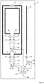
- the highly integrated active multiband antenna according to the illustrations after Figure 1 to 3 consists first of a first loop-shaped conductor 1 and a second loop-shaped conductor 2, which is delimited from the first loop-shaped conductor 1. Furthermore, a stub 3 is present, which preferably runs parallel to one of the longer sides of the first loop-shaped conductor 1.
- the loop-shaped conductor tracks 1 and 2 and the stub line 3 are preferably located on a planar dielectric support, for example a foil-like printed circuit board.
- the first loop-shaped conductor 1, which is tuned for the frequency band 1, that is FM, has an interruption on one of its conductor track sides, which is bridged by a first adaptation circuit 5.
- the opposite side of the first loop-shaped conductor track has two closely adjacent ends 6 and 7.
- One of these ends is connected to the input of a first frequency filter 8 and the second of these ends 7 is connected to the input of a second frequency filter 9.
- the outputs of the frequency filters 8 and 9 are connected to the balanced inputs of a first balun 10.
- the unbalanced output of the first balun 10 is connected to the input of a first amplifier 11.
- the output 12 of the first amplifier 11 forms the output terminal of the first frequency band FM.
- the second loop-shaped track 2 which is tuned for the DAB frequency band, has two closely adjacent ends 13 and 14.
- a first end 13 is connected to the input of another matching circuit 15 and a second end 14 is connected to the input of the matching circuit 16.
- the output of the matching circuit 15 is connected to the input of another frequency filter 17 and the output of the matching circuit 16 to the input of a frequency filter 18 in combination.
- the outputs of the frequency filters 17 and 18 are connected to the balanced inputs of a second balun 19.
- the unbalanced output of the second balun 19 is connected to the input of a second amplifier 20.
- the output 21 of the second amplifier 20 forms the output terminal for the second frequency band, that is the DAB band.
- the stub 3 which is located on the dielectric support 4, forms a monopole for the AM frequency band.
- One end of the stub 3 is connected to the input of a frequency filter 22 whose output is connected to the input of a third amplifier 23 in connection.
- the output 24 of the third amplifier 23 represents the connection for the AM frequency band.
- the terminals 12 and 24 for the first and the third frequency band are connected to the inputs 25 and 26 of a splitter.
- the splitter has an output 27 for selectively tapping corresponding signals of said frequency bands.
- the output 21 for the second frequency band is as a separate coaxial output in the embodiment according to FIG. 2 realized.
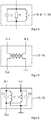
- the frequency filters (8; 9; 17; 18) after FIG. 4 is an inductive component L parallel to a capacitive element C and an electrical resistance R turned on. They form a parallel resonant circuit.
- the resonance frequency of the frequency filters 8 and 9 is in the middle region of the second frequency band DAB.
- the resonant frequency of the frequency filters 17 and 18 is in the middle region of the first frequency band FM. This is the maximum decoupling between the reception structures for the FM and DAB frequency bands and ensures maximum reception quality in the FM and DAB frequency bands.
- the mean frequency f 0 of the corresponding frequency band FM or DAB is designated.
- F 2 and f 1 denote the upper and lower frequencies of the frequency band.
- R denotes the load resistance R of the frequency filter.
- the load resistor R has a resistance of 150 ohms to 300 ohms.
- the balun (10; 19) is implemented as an HF transformer / balun for converting a symmetrical received signal into a single-ended signal.
- the balun has two balanced inputs In1 and In2 and one unbalanced output Out.
- FIG. 6 illustrates the preferred embodiment of the balun (10; 19) as a bridge circuit consisting of two capacitances C1, C2 and two inductors L1, L2.
- the balun has two balanced inputs In1 and In2 and one unbalanced output Out. Paired together first terminals of a first capacitance C1 and a first inductance L1 and a second capacitance C2 and a second inductance L2 form a first balanced input In1 and a second balanced input In2 of the balun.
- a second terminal of the capacitor C1 is connected to the second terminal of an inductor L2 and forms an unbalanced output Out of the balun, whose ground-connected output is formed by interconnected second terminals of the capacitance C2 and the inductance L1.
- the inductances and the capacitances can be determined according to the regulations (1), (2), and (3).
Landscapes
- Physics & Mathematics (AREA)
- Electromagnetism (AREA)
- Details Of Aerials (AREA)
Abstract
Description
- Die Erfindung betrifft eine aktive Multiband-Antenne für den terrestrischen Rundfunkempfang, umfassend Empfangsstrukturen, bestehend aus Schleifen- und stichförmige Leiterbahnen, welche auf einem dielektrischen Träger angeordnet sind, sowie in den Anschlussbereichen der Empfangsstrukturen vorgesehenen Anpassungsschaltungen, Frequenzfiltern, Symmetrierglieder und Verstärkerschaltungen gemäß Oberbegriff des Anspruches 1.
- Aus der
US 4 791 426 B1 oder derUS 6 215 450 B1 sind Heckscheibenantennen vorbekannt. In dem Fall, wenn zum Beispiel durch Druck aufgebrachte Heizungselemente der Scheibe als Antennenstrahler genutzt werden, sind Entkopplungsfilter notwendig, um den Heizgleichstrom von den Hochfrequenzsignalen zu trennen. Derartige Entkopplungsfilter sind großbauend und teuer. Im Falle defekter Heizleiterschleifen verliert die Antenne den gewünschten Wirkungsgrad oder ihre Funktion insgesamt. - Aus der
DE 34 10 415 A1 ist eine aktive Antenne für die Heckscheibe eines Fahrzeuges vorbekannt. Diese Antenne soll sowohl einen AM-Empfang im Lang-, Mittel- und Kurzwellenbereich als auch einen FM-Empfang, das heißt im UKW-Bereich, ermöglichen. Bei dieser Antenne wird ein weiterer, mit dem Heizfeld galvanisch nicht verbundener, flächenhaft ausgebildeter Antennenleiter auf der Scheibe erzeugt. Dieser Antennenleiter steht mit dem Anschluss einer Eingangsklemme eines rauscharmen Verstärkers mit kapazitiv hochohmigen Eingangswiderstand in Verbindung. Die Masseverbindung des Antennenverstärkers ist über eine kurze Leitung mit der Umrandung des leitfähigen Teiles der Heckscheibe verbunden. Die entsprechenden Abstände und Querabmessungen des Antennenleiters bezogen auf die Berandung und das Heizfeld selbst unterliegen einer bestimmten Dimensionierung, die fahrzeugspezifisch ist und nicht für alle Frequenz- und Empfangsverhältnisse optimiert werden kann. - Aus der
WO 02/05236 A1 - Zum Stand der Technik gehört weiterhin die
DE 10 2010 010 371 B4 . Aus diesem Dokument ist eine aktive Antenne für Mehrfrequenz-Diversity-Empfang umfassend eine schleifenförmige Leiterbahn mit durch einen Kondensator überbrückter Unterbrechung und einem Anschlussbereich vorbekannt, wobei im Anschlussbereich die Primärseite eines Anpassungstransformators angeschlossen ist, dessen Sekundärseite auf eine Verstärkerschaltung führt. Die schleifenförmige Leiterbahn steht mit einer Stichleitung in Verbindung, wobei das von der schleifenförmigen Leiterbahn entfernte Ende der Stichleitung an der Sekundärseite des Anpassungstransformators angeschlossen ist, so dass durch die Wahl des Verbindungspunktes zwischen der Stichleitung und der schleifenförmigen Leiterbahn eine Abstimmung auf die elektrische Feldkomponente und die diesbezügliche Eingangsimpedanz der Verstärkerschaltung im FM-Bereich erfolgt. - Ausgehend vom geschilderten Stand der Technik ist es Aufgabe der Erfindung, eine weiterentwickelte aktive Multiband-Antenne für den terrestrischen Rundfunkempfang auf der Basis schleifenförmiger Leiterbahnen anzugeben, welche auf aufwändige Anpassung von Transformatoren weitgehend verzichtet und die in der Lage ist, optimale Empfangseigenschaften bei ausreichender Selektivität über ganz unterschiedliche Frequenzbereiche bzw. Frequenzbänder zu gewährleisten, wobei die Flächenausdehnung der Multiband-Antenne möglichst klein ist, um diese insbesondere als Multiband-Klebeantenne an den verschiedensten Stellen, insbesondere eines Kraftfahrzeuges anordnen zu können.
- Die Lösung der Aufgabe der Erfindung erfolgt mit einer aktiven Multiband-Antenne gemäß der Merkmalskombination nach Anspruch 1, wobei die Unteransprüche mindestens zweckmäßige Ausführungsformen bzw. eine bevorzugte Anwendung darstellen.
- Es wird demnach von einer aktiven Multiband-Antenne ausgegangen, die für den terrestrischen Rundfunkempfang vorgesehen ist.
- Diese aktive Multiband-Antenne umfasst Empfangsstrukturen, bestehend aus schleifen- und stichförmigen Leiterbahnen, welche auf einem dielektrischen Träger angeordnet sind. Weiterhin sind in Anschlussbereichen der Empfangsstrukturen Anpassungsschaltungen, Frequenzfilter, Symmetrierglieder und Verstärkerschaltungen vorgesehen.
- Die aktive Multiband-Antenne ist erd-symmetrisch und braucht keine Masseverbindung mit der Fahrzeugkarosserie, was die Montage der Antenne am Fahrzeug vereinfacht.
- Erfindungsgemäß ist eine erste schleifenförmige Leiterbahn auf ein erstes Frequenzband FM abgestimmt ausgebildet. Diese erste schleifenförmige Leiterbahn weist eine Unterbrechung auf, die sich an einem vom Antennenanschluss entfernten Ende befindet.
- Die Unterbrechung wird mit einer ersten Anpassungsschaltung überbrückt.
- Im Anschlussbereich der ersten schleifenförmigen Leiterbahn, deren Anschlussenden dicht benachbart sind, sind ein erstes und ein zweites Frequenzfilter vorgesehen, die im zweiten Frequenzband (DAB) eine hohe Lastimpedanz für die erste schleifenförmige Leiterbahn aufweisen und dadurch deren Nahfeld-Kopplung an eine zweite schleifenförmige Leiterbahn minimieren.
- Die jeweiligen Ausgänge des ersten und des zweiten Frequenzfilters stehen mit den symmetrischen Eingängen eines ersten Symmetriergliedes in Verbindung, wobei der unsymmetrische Ausgang des Symmetriergliedes am Eingang eines ersten Verstärkers anliegt.
- Der Ausgang des ersten Verstärkers bildet den Ausgangsanschluss für das erste Frequenzband FM.
- Die zweite schleifenförmige Leiterbahn, die auf das zweite Frequenzband DAB abgestimmt ausgebildet ist, wird abgegrenzt von der ersten schleifenförmigen Leiterbahn auf dem dielektrischen Träger angeordnet.
- Im Anschlussbereich der zweiten schleifenförmigen Leiterbahn für das zweite Frequenzband DAB ist eine zweite und eine dritte Anpassungsschaltung vorgesehen, deren jeweiliger Ausgang auf ein drittes und ein viertes Frequenzfilter führt. Diese Frequenzfilter weisen im ersten Frequenzband FM eine hohe Lastimpedanz für die zweite schleifenförmige Leiterbahn auf und können dadurch deren Nahfeld-Kopplung an die erste schleifenförmige Leiterbahn (1) minimieren.
- Der jeweilige Ausgang des dritten und vierten Frequenzfilters ist mit den symmetrischen Eingängen eines zweiten Symmetriergliedes verbunden.
- Der unsymmetrische Ausgang des zweiten Symmetriergliedes liegt am Eingang eines zweiten Verstärkers an. Der Ausgang des zweiten Verstärkers bildet nun den Anschluss für das zweite Frequenzband DAB.
- Weiterhin ist im Wesentlichen parallel zur längeren Ausdehnung der ersten schleifenförmigen Leiterbahn eine, auf ein drittes Frequenzband AM abgestimmte Monopol-Stichleitung ausgebildet. Das Speiseende der Monopol-Stichleitung steht über ein Frequenzfilter mit dem Eingang eines dritten Verstärkers in Verbindung. Der Ausgang des dritten Verstärkers bildet den Anschluss für das dritte Frequenzband AM.
- In einer Weiterbildung der Erfindung weisen die schleifenförmigen Leiterbahnen eine im Wesentlichen rechteckige Ausbildung auf.
- Dabei kann die erste schleifenförmige Leiterbahn die zweite schleifenförmige Leiterbahn beabstandet umgeben, so dass quasi eine Verschachtelung vorliegt.
- Die Leiterbahnen bilden bevorzugt eine planare Struktur.
- In Ausgestaltung der Erfindung weist der dielektrische Träger eine Schicht oder eine Beschichtung zum Aufkleben auf eine insbesondere Kunststoff- oder Glasfläche auf.
- Die Anschlüsse für die jeweiligen Frequenzbänder können als separate Koaxialausgänge ausgebildet werden.
- Alternativ ist es aber möglich, die Ausgänge für die Frequenzbänder vollständig oder für wenigstens zwei Frequenzbänder gesplittet auszubilden.
- Die Länge der schleifenförmigen Leiterbahnen ist bevorzugt ≤ dem 0,2-fachen der kleinsten Wellenlänge des jeweiligen gewünschten Empfangsbereiches.
- In einer bevorzugten Weiterbildung der Erfindung können alle wesentlichen Antennenbauteile auf einem dielektrischen Folien-Verdrahtungsträger angeordnet werden.
- Dieser Folien-Verdrahtungsträger kann dann auf einer Seite die bereits erwähnte Klebebeschichtung aufweisen, um ein Aufkleben im Sinne einer Glasklebeantenne zu bewerkstelligen.
- Erfindungsgemäß ist darüber hinaus die Anwendung der vorgestellten Multiband-Antenne für den Bereich Kraftfahrzeuge, hier wiederum insbesondere für PKW, Reisemobile, Busse bzw. Nutzfahrzeuge.
- Die Erfindung stellt also ein hochintegriertes aktives Multiband-Antennensystem für den terrestrischen Radioempfang der Frequenzbänder FM, DAB und AM dar und geht von einer ersten und einer zweiten schleifenförmigen Leiterbahn aus.
- Die erste schleifenförmige Leiterbahn besitzt eine durch eine Anpassschaltung überbrückte Unterbrechung und einen Anschlussbereich.
- Der Anschlussbereich ist über die erwähnten Frequenzfilter, die für die Entkopplung der FM und DAB Empfangsstrukturen vorgesehen sind, mit dem ersten Symmetrierglied verbunden, wobei dessen Ausgang mit dem Eingang einer Verstärkerschaltung verbunden ist, die wiederum den Ausgang des Antennensystems für das erste Frequenzband FM darstellt.
- Die erste schleifenförmige Leiterbahn grenzt die zweite schleifenförmige Leiterbahn ab und umgibt diese in bevorzugter Ausführungsform.
- Auch die Enden der zweiten schleifenförmigen Leiterbahn sind durch Anpassungsschaltungen für das zweite Frequenzband DAB und mittels Frequenzfilter für das erste Frequenzband FM mit den symmetrischen Eingängen eines zweiten Symmetriergliedes verbunden, dessen unsymmetrischen Ausgang mit dem Eingang eines zweiten Verstärkers verbunden ist.
- Der Ausgang des zweiten Verstärkers bildet wiederum den Ausgang des Antennensystems für das zweite Frequenzband DAB.
- Besonders erfindungsgemäß ist der Ansatz, parallel zur längeren Seite der ersten schleifenförmigen Leiterbahn einen Monopol anzuordnen, dessen eines Ende über einen Frequenzfilter mit dem Eingang eines dritten Verstärkers verbunden ist, dessen Ausgang den Ausgang des Antennensystems für das AM-Frequenzband bildet.
- Die vorgestellte Multiband-Antenne ist aufgrund ihrer planaren Struktur und der kompakten Ausbildung sowie der vorhandenen Entkopplung insbesondere für Anwendungen im Bereich der Kraftfahrzeugtechnik geeignet und hier insbesondere vom Typ der Fahrzeugkarosserie unabhängig.
- Die Erfindung soll nachstehend anhand eines Ausführungsbeispieles näher erläutert werden.
- Hierbei zeigen:
- Fig. 1
- ein Blockschaltbild der prinzipiellen Ausführungsform der erfindungsgemäßen Multiband-Antenne mit separaten koaxialen Ausgängen für die einzelnen Frequenzbänder;
- Fig. 2
- eine Darstellung eines Blockschaltbildes analog der ersten Ausführungsform der Erfindung, jedoch mit gesplittetem Ausgang für die Frequenzbänder 1 und 3, das heißt FM und AM; und
- Fig. 3
- ein Blockschaltbild einer Ausführungsform mit gesplittetem Koaxialausgang für alle Frequenzbänder, das heißt FM, DAB und AM;
- Fig. 4
- ein beispielhaftes Frequenzfilter;
- Fig. 5
- ein elektrisches Symmetrierglied bestehend aus HF Transformator zur Anwendung gemäß Ausführungsbeispiel; und
- Fig. 6
- ein Ersatzschaltbild eines Symmetriergliedes aus diskreten kapazitiven und induktiven Bauelementen als Brückenschaltung.
- Die hochintegrierte aktive Multiband-Antenne gemäß den Darstellungen nach
Figur 1 bis 3 besteht zunächst aus einer ersten schleifenförmigen Leiterbahn 1 und einer zweiten schleifenförmigen Leiterbahn 2, die von der ersten schleifenförmigen Leiterbahn 1 abgegrenzt ist. Weiterhin ist eine Stichleitung 3 vorhanden, die bevorzugt parallel zu einer der längeren Seiten der ersten schleifenförmigen Leiterbahn 1 verläuft. - Die schleifenförmigen Leiterbahnen 1 und 2 sowie die Stichleitung 3 befinden sich bevorzugt auf einem planaren dielektrischen Träger, zum Beispiel einer folienartigen Leiterplatte.
- Die erste schleifenförmige Leiterbahn 1, die für das Frequenzband 1, das heißt FM, abgestimmt ist, weist auf einer ihrer Leiterbahnseiten eine Unterbrechung auf, welche durch eine erste Anpassungsschaltung 5 überbrückt wird.
- Die gegenüberliegende Seite der ersten schleifenförmigen Leiterbahn hat zwei dicht benachbarte Enden 6 und 7.
- Eines dieser Enden ist mit dem Eingang eines ersten Frequenzfilters 8 und das zweite dieser Enden 7 ist mit dem Eingang eines zweiten Frequenzfilters 9 verbunden.
- Die Ausgänge der Frequenzfilter 8 und 9 sind mit den symmetrischen Eingängen eines ersten Symmetriergliedes 10 verbunden.
- Der unsymmetrische Ausgang des ersten Symmetriergliedes 10 ist am Eingang eines ersten Verstärkers 11 angeschlossen. Der Ausgang 12 des ersten Verstärkers 11 bildet den Ausgangsanschluss des ersten Frequenzbandes FM.
- Die zweite schleifenförmige Leiterbahn 2, die für das DAB-Frequenzband abgestimmt ist, weist zwei dicht benachbarte Enden 13 und 14 auf.
- Ein erstes Ende 13 ist mit dem Eingang einer weiteren Anpassungsschaltung 15 und ein zweites Ende 14 mit dem Eingang der Anpassungsschaltung 16 verbunden.
- Der Ausgang der Anpassungsschaltung 15 steht mit dem Eingang eines weiteren Frequenzfilters 17 und der Ausgang der Anpassungsschaltung 16 mit dem Eingang eines Frequenzfilters 18 in Verbindung.
- Die Ausgänge der Frequenzfilter 17 und 18 sind mit den symmetrischen Eingängen eines zweiten Symmetriergliedes 19 verbunden.
- Der unsymmetrische Ausgang des zweiten Symmetriergliedes 19 ist am Eingang eines zweiten Verstärkers 20 angeschlossen.
- Der Ausgang 21 des zweiten Verstärkers 20 bildet den Ausgangsanschluss für das zweite Frequenzband, das heißt das DAB-Band.
- Die Stichleitung 3, die auf dem dielektrischen Träger 4 befindlich ist, bildet einen Monopol für das AM-Frequenzband.
- Ein Ende der Stichleitung 3 ist mit dem Eingang eines Frequenzfilters 22 verbunden, dessen Ausgang mit dem Eingang eines dritten Verstärkers 23 in Verbindung steht.
- Der Ausgang 24 des dritten Verstärkers 23 stellt den Anschluss für das AM-Frequenzband dar.
- Bei der Darstellung nach
Figur 2 stehen die Anschlüsse 12 und 24 für das erste und das dritte Frequenzband mit den Eingängen 25 und 26 eines Splitters in Verbindung. - Der Splitter weist einen Ausgang 27 zum wahlweisen Abgriff entsprechender Signale der genannten Frequenzbänder auf.
- Der Ausgang 21 für das zweite Frequenzband ist als separater Koaxialausgang bei der Ausführungsform nach
Figur 2 realisiert. - Bei der Ausführungsform nach
Figur 3 ist auch der Ausgang 21 des zweiten Frequenzbandes auf einen weiteren Eingang 28 eines Splitters geführt an dessen Ausgang 27 die Signale der relevanten Frequenzbänder FM, AM und DAB abgreifbar sind. - Bei der Ausführungsform der Frequenzfilter (8; 9; 17; 18) nach
Figur 4 ist ein induktives Bauelement L parallel zu einem kapazitiven Bauelement C und einem elektrischen Widerstand R eingeschaltet. Sie bilden einen Parallelschwingkreis aus. Die Resonanzfrequenz der Frequenzfilter 8 und 9 liegt im mittleren Bereich des zweiten Frequenzbandes DAB. Die Resonanzfrequenz der Frequenzfilter 17 und 18 liegt im mittleren Bereich des ersten Frequenzbandes FM. Damit wird die maximale Entkopplung zwischen den Empfangsstrukturen für die FM und DAB Frequenzbänder erzeugt und maximale Empfangsqualität in den FM und DAB Frequenzbändern gewährleistet. - Die Induktivität L und die Kapazität C des Frequenzfilters können gemäß folgenden Beziehungen ermittelt werden:


- Mit

Die FM und DAB Frequenzbänder haben entsprechende Bandbreiten 20 MHz und 60 MHz mit mittleren Frequenzen 98 MHz und 200 MHz.
Diesen Bandbreiten entspricht der Gütefaktor Q
- Mit f 2 und f 1 werden die obere und die untere Frequenz des Frequenzbandes bezeichnet. Der Gütefaktor Q kann durch die Frequenzfilterparameter definiert werden:

- Mit R wird der Lastwiderstand R des Frequenzfilters bezeichnet.
Der Lastwiderstand R kann gemäß der Formel (5) ermittelt werden:
- Um die entsprechende Bandbreite zu gewährleisten, weist der Lastwiderstand R einen Widerstandwert von 150 Ohm bis 300 Ohm auf.
- Bei der Ausführungsform nach
Figur 5 ist das Symmetrierglied (10; 19) als HF Transformator/Balun realisiert zum Umwandeln eines symmetrischen Empfangssignals in ein unsymmetrisches Signal. Das Symmetrierglied hat zwei symmetrische Eingänge In1 und In2 und einen unsymmetrischen Ausgang Out. -
Figur 6 stellt die bevorzugte Ausführungsform des Symmetriergliedes (10; 19) als eine Brückenschaltung dar, die aus zwei Kapazitäten C1, C2 und zwei Induktivitäten L1, L2 besteht. Das Symmetrierglied hat zwei symmetrischen Eingängen In1 und In2 und einen unsymmetrischen Ausgang Out. Paarweise zusammengeschaltete erste Anschlüsse einer ersten Kapazität C1 und einer ersten Induktivität L1 bzw. einer zweiten Kapazität C2 und einer zweiten Induktivität L2 bilden einen ersten symmetrischen Eingang In1 bzw. einen zweiten symmetrischen Eingang In2 des Symmetriergliedes aus. Ein zweiter Anschluss der Kapazität C1 ist mit dem zweiten Anschluss einer induktiven Bauelementes L2 zusammengeschaltet und bildet einen unsymmetrischen Ausgang Out des Symmetriergliedes, dessen erd-verbundener Ausgang ist von zusammengeschalteten zweiten Anschlüssen der Kapazität C2 und der Induktivität L1 ausgebildet. - Die Induktivitäten und die Kapazitäten können gemäß den Vorschriften (1), (2), und (3) ermittelt werden.
Claims (14)
- Aktive Multiband-Antenne für den terrestrischen Rundfunkempfang, umfassend Empfangsstrukturen, bestehend aus schleifen- und stichförmigen Leiterbahnen, welche auf einem dielektrischen Träger (4) angeordnet sind, sowie in den Anschlussbereichen der Empfangsstrukturen vorgesehenen Anpassungsschaltungen, Frequenzfiltern, Symmetrierglieder und Verstärkerschaltungen,
dadurch gekennzeichnet, dass
eine erste schleifenförmige Leiterbahn (1) auf ein erstes Frequenzband (FM) abgestimmt ausgebildet ist, wobei diese erste schleifenförmige Leiterbahn (1) eine Unterbrechung aufweist, welche mit einer ersten Anpassungsschaltung (5) überbrückt ist,
im Anschlussbereich (6; 7) der ersten schleifenförmigen Leiterbahn (1) ein erstes und ein zweites Frequenzfilter (8; 9) vorgesehen ist, die im zweiten Frequenzband (DAB) eine hohe Lastimpedanz für die erste schleifenförmige Leiterbahn (1) aufweisen und dadurch deren Nahfeld-Kopplung an eine zweite schleifenförmige Leiterbahn (2) minimieren, wobei die jeweiligen Ausgänge des ersten und des zweiten Frequenzfilters (8; 9) mit den symmetrischen Eingängen eines ersten Symmetriergliedes (10) verbunden sind, wobei der unsymmetrische Ausgang des Symmetriergliedes (10) am Eingang eines ersten Verstärkers (11) anliegt und der Ausgang (12) des ersten Verstärkers (11) den Anschluss für das erste Frequenzband (FM) bildet,
die zweite schleifenförmige Leiterbahn (2) auf das zweite Frequenzband (DAB) abgestimmt ausgebildet ist, wobei im Anschlussbereich (13; 14) der zweiten schleifenförmigen Leiterbahn (2) eine zweite und eine dritte Anpassungsschaltung (15; 16) vorgesehen ist, deren jeweilige Ausgänge auf Eingänge eines dritten und eines vierten Frequenzfilters (17; 18) geführt sind, die im ersten Frequenzband (FM) eine hohe Lastimpedanz für die zweite schleifenförmige Leiterbahn (2) aufweisen und dadurch deren Nahfeld-Kopplung an die erste schleifenförmige Leiterbahn (1) minimieren, wobei der jeweilige Ausgang des dritten und des vierten Frequenzfilters (17; 18) mit den symmetrischen Eingängen eines zweiten Symmetriergliedes (19) verbunden ist, der unsymmetrische Ausgang des zweiten Symmetriergliedes (19) am Eingang eines zweiten Verstärkers (20) anliegt und der Ausgang (21) des zweiten Verstärkers (20) den Anschluss für das zweite Frequenzband (DAB) bildet, weiterhin im Wesentlichen parallel zur längeren Ausdehnung der ersten schleifenförmigen Leiterbahn (1) eine auf ein drittes Frequenzband (AM) abgestimmte Monopol-Stichleitung (3) ausgebildet ist, deren Speiseende über einen Frequenzfilter (22) mit dem Eingang eines dritten Verstärkers (23) in Verbindung steht, dessen Ausgang (24) den Anschluss für das dritte Frequenzband (AM) bildet, wobei der Eingang des Frequenzfilters (22) im ersten Frequenzband (FM) und zweiten Frequenzband (DAB) eine hohe Lastimpedanz für die Monopol-Stichleitung (3) aufweist und dadurch deren Nahfeld-Kopplung an die ersten und zweiten schleifenförmigen Leiterbahnen (1; 2) minimiert. - Antenne nach Anspruch 1,
dadurch gekennzeichnet, dass
die schleifenförmigen Leiterbahnen (1; 2) eine im Wesentlichen rechteckige Ausbildung aufweisen. - Antenne nach Anspruch 2,
dadurch gekennzeichnet, dass
die erste schleifenförmige Leiterbahn (1) die zweite schleifenförmige Leiterbahn (2) beabstandet umgibt. - Antenne nach einem der vorangegangenen Ansprüche,
dadurch gekennzeichnet, dass
die Leiterbahnen (1; 2) sowie die Stichleitung (3) eine planare Struktur bilden. - Antenne nach einem der vorangegangenen Ansprüche,
dadurch gekennzeichnet, dass
der dielektrische Träger (4) eine Schicht zum Aufkleben auf eine insbesondere Kunststoff- oder Glasoberfläche aufweist. - Antenne nach einem der vorangegangenen Ansprüche,
dadurch gekennzeichnet, dass
die Anschlüsse für die jeweiligen Frequenzbänder (AM; FM; DAB) jeweils als Koaxialausgang ausgebildet sind. - Antenne nach einem der Ansprüche 1 bis 5,
dadurch gekennzeichnet, dass
die Ausgänge für die Frequenzbänder (AM; FM; DAB) vollständig oder für wenigstens zwei Frequenzbänder gesplittet ausgebildet sind. - Antenne nach einem der vorangegangenen Ansprüche,
dadurch gekennzeichnet, dass
die Länge der schleifenförmigen Leiterbahnen ≤ dem 0,2-fachen der kleinsten Wellenlänge des jeweiligen gewünschten Empfangsbereiches ist. - Antenne nach einem der vorangegangenen Ansprüche,
dadurch gekennzeichnet, dass
im Wesentlichen alle Antennenbauteile auf einem dielektrischen Folien-Verdrahtungsträger angeordnet sind. - Antenne nach einem oder mehreren der vorangegangenen Ansprüche, gekennzeichnet durch
deren Verwendung im Bereich Kraftfahrzeuge, hier insbesondere Personenkraftwagen und Nutzfahrzeugen. - Antenne nach einem oder mehreren der vorangegangenen Ansprüche, dadurch gekennzeichnet, dass
die Unterbrechung der ersten schleifenförmigen Leiterbahn (1) vom Anschlussbereich (6; 7) entfernt angeordnet ist. - Antenne nach einem oder mehreren der vorangegangenen Ansprüche, dadurch gekennzeichnet, dass
die Anpassungsschaltungen (5; 15; 16) Kondensatoren aufweisen. - Antenne nach Anspruch 12,
dadurch gekennzeichnet, dass
die Anpassungsschaltungen (5; 15; 16) als Planarkondensatoren auf einem gemeinsamen mit anderen Antennenbauteilen dielektrischen Verdrahtungsträger ausgebildet sind. - Antenne nach einem oder mehreren der vorangegangenen Ansprüche, dadurch gekennzeichnet, dass
die Frequenzfilter (8; 9; 17; 18) als Parallelschwingkreis mit einer Induktivität, einem elektrischen Widerstand und einer Kapazität ausgebildet sind, wobei die Resonanzfrequenz der Frequenzfilter (8; 9) auf den mittleren Frequenzen des zweiten Frequenzbandes (DAB) und die Resonanzfrequenz der Frequenzfiltern (17; 18) auf den mittleren Frequenzen des ersten Frequenzbandes (FM) liegt, wobei der Widerstandswert 150 Ohm bis 300 Ohm beträgt.
Applications Claiming Priority (2)
| Application Number | Priority Date | Filing Date | Title |
|---|---|---|---|
| DE102017128286 | 2017-11-29 | ||
| DE102018106095.5A DE102018106095B3 (de) | 2017-11-29 | 2018-03-15 | Aktive Multiband-Antenne für den terrestrischen Rundfunkempfang |
Publications (2)
| Publication Number | Publication Date |
|---|---|
| EP3493324A1 true EP3493324A1 (de) | 2019-06-05 |
| EP3493324B1 EP3493324B1 (de) | 2021-03-17 |
Family
ID=65004434
Family Applications (1)
| Application Number | Title | Priority Date | Filing Date |
|---|---|---|---|
| EP18207439.3A Active EP3493324B1 (de) | 2017-11-29 | 2018-11-21 | Aktive multiband-antenne für den terrestrischen rundfunkempfang |
Country Status (2)
| Country | Link |
|---|---|
| EP (1) | EP3493324B1 (de) |
| DE (1) | DE102018106095B3 (de) |
Citations (9)
| Publication number | Priority date | Publication date | Assignee | Title |
|---|---|---|---|---|
| US4518965A (en) * | 1981-02-27 | 1985-05-21 | Tokyo Shibaura Denki Kabushiki Kaisha | Tuned small loop antenna and method for designing thereof |
| DE3410415A1 (de) | 1984-03-21 | 1985-09-26 | Gerhard Prof. Dr.-Ing. 8012 Ottobrunn Flachenecker | Aktive antenne in der heckscheibe eines kraftfahrzeugs |
| JPH03108903A (ja) * | 1989-09-22 | 1991-05-09 | Nippon Sheet Glass Co Ltd | 広帯域ループアンテナ |
| US5402134A (en) * | 1993-03-01 | 1995-03-28 | R. A. Miller Industries, Inc. | Flat plate antenna module |
| WO2000041268A1 (en) * | 1999-01-05 | 2000-07-13 | Tevca Technologies, Inc. | Box-kite uhf/vhf television and radio communications antenna |
| US6215450B1 (en) | 1998-06-03 | 2001-04-10 | Nippon Sheet Glass Co., Ltd. | Glass window antenna system for motor vehicles |
| WO2002005236A1 (en) | 2000-07-06 | 2002-01-17 | C. Crane Company | Twin coil antenna |
| US20050156798A1 (en) * | 2004-01-16 | 2005-07-21 | Bally Nazar F. | Am/fm on-glass wire grid antenna |
| DE102010010371B4 (de) | 2010-02-19 | 2011-12-22 | Antennentechnik Bad Blankenburg Ag | Aktive Antenne für Mehrfrequenz-Diversity-Empfang |
-
2018
- 2018-03-15 DE DE102018106095.5A patent/DE102018106095B3/de not_active Expired - Fee Related
- 2018-11-21 EP EP18207439.3A patent/EP3493324B1/de active Active
Patent Citations (10)
| Publication number | Priority date | Publication date | Assignee | Title |
|---|---|---|---|---|
| US4518965A (en) * | 1981-02-27 | 1985-05-21 | Tokyo Shibaura Denki Kabushiki Kaisha | Tuned small loop antenna and method for designing thereof |
| DE3410415A1 (de) | 1984-03-21 | 1985-09-26 | Gerhard Prof. Dr.-Ing. 8012 Ottobrunn Flachenecker | Aktive antenne in der heckscheibe eines kraftfahrzeugs |
| US4791426A (en) | 1984-03-21 | 1988-12-13 | Hans Kolbe & Co. | Active antenna in the rear window of a motor vehicle |
| JPH03108903A (ja) * | 1989-09-22 | 1991-05-09 | Nippon Sheet Glass Co Ltd | 広帯域ループアンテナ |
| US5402134A (en) * | 1993-03-01 | 1995-03-28 | R. A. Miller Industries, Inc. | Flat plate antenna module |
| US6215450B1 (en) | 1998-06-03 | 2001-04-10 | Nippon Sheet Glass Co., Ltd. | Glass window antenna system for motor vehicles |
| WO2000041268A1 (en) * | 1999-01-05 | 2000-07-13 | Tevca Technologies, Inc. | Box-kite uhf/vhf television and radio communications antenna |
| WO2002005236A1 (en) | 2000-07-06 | 2002-01-17 | C. Crane Company | Twin coil antenna |
| US20050156798A1 (en) * | 2004-01-16 | 2005-07-21 | Bally Nazar F. | Am/fm on-glass wire grid antenna |
| DE102010010371B4 (de) | 2010-02-19 | 2011-12-22 | Antennentechnik Bad Blankenburg Ag | Aktive Antenne für Mehrfrequenz-Diversity-Empfang |
Non-Patent Citations (1)
| Title |
|---|
| GIBSON J J ET AL: "THE MINI-STATE-A SMALL TELEVISION ANTENNA", IEEE TRANSACTIONS ON CONSUMER ELECTRONICS,, vol. CE-22, no. 2, 1 May 1976 (1976-05-01), pages 159 - 165, XP001382313 * |
Also Published As
| Publication number | Publication date |
|---|---|
| EP3493324B1 (de) | 2021-03-17 |
| DE102018106095B3 (de) | 2019-01-31 |
Similar Documents
| Publication | Publication Date | Title |
|---|---|---|
| EP1619752B1 (de) | Antennenmodul | |
| DE69221355T2 (de) | Scheibenantennensystem für Kraftfahrzeug | |
| EP0155647B1 (de) | Antennenanordnung in der Heckscheibe eines Kraftfahrzeugs | |
| EP0269723B1 (de) | Diversity-antennenanordnung | |
| DE68922797T2 (de) | Kraftfahrzeugantenne. | |
| DE102014225717A1 (de) | Zweiband-PCB-Antenne für ein Fahrzeug | |
| DE2650044B2 (de) | Schaltungsanordnung zum Empfangen von hochfrequenten Rundfunksignalen | |
| DE102008050743A1 (de) | Impedanzanpass-Schaltung zur Anpassung von Planarantennen | |
| DE10022107A1 (de) | Integrierte Antenne für Mobilfunktelefone | |
| EP0505673A1 (de) | Stabförmiger Mehrbereichsstrahler | |
| DE69506435T2 (de) | Antenne | |
| EP2225795B1 (de) | Antennenfeld für eine kraftfahrzeug-scheibe | |
| DE2115657B2 (de) | Aktive Unipol-Empfangsantenne | |
| EP1540767A1 (de) | Antennenanordnung mit einem flächendipol | |
| EP1005101A2 (de) | Fensterscheibenantenne mit hochfrequent hochohmig angeschlossenem Heizfeld | |
| DE102019214124A1 (de) | Antennenvorrichtung und Fahrzeug aufweisend eine Antennenvorrichtung | |
| DE102014016851B3 (de) | MIMO Schlitzantenne für Kraftfahrzeuge | |
| DE4216376C2 (de) | Fahrzeug-Antennenanordnung mit einer Empfangsschaltung für den LMK-Bereich | |
| DE102018106095B3 (de) | Aktive Multiband-Antenne für den terrestrischen Rundfunkempfang | |
| WO1992021160A1 (de) | Antennenanordnung | |
| EP2248221B1 (de) | Antennenanordnung für ein kraftfahrzeug | |
| EP0166387B1 (de) | Antenne in der Heckscheibe eines Kraftfahrzeugs | |
| WO2004082072A1 (de) | Multibandantenne mit endkapazität | |
| DE102010010371B4 (de) | Aktive Antenne für Mehrfrequenz-Diversity-Empfang | |
| DE102004027839B4 (de) | Antennenstruktur |
Legal Events
| Date | Code | Title | Description |
|---|---|---|---|
| PUAI | Public reference made under article 153(3) epc to a published international application that has entered the european phase |
Free format text: ORIGINAL CODE: 0009012 |
|
| STAA | Information on the status of an ep patent application or granted ep patent |
Free format text: STATUS: THE APPLICATION HAS BEEN PUBLISHED |
|
| AK | Designated contracting states |
Kind code of ref document: A1 Designated state(s): AL AT BE BG CH CY CZ DE DK EE ES FI FR GB GR HR HU IE IS IT LI LT LU LV MC MK MT NL NO PL PT RO RS SE SI SK SM TR |
|
| AX | Request for extension of the european patent |
Extension state: BA ME |
|
| STAA | Information on the status of an ep patent application or granted ep patent |
Free format text: STATUS: REQUEST FOR EXAMINATION WAS MADE |
|
| 17P | Request for examination filed |
Effective date: 20190620 |
|
| RBV | Designated contracting states (corrected) |
Designated state(s): AL AT BE BG CH CY CZ DE DK EE ES FI FR GB GR HR HU IE IS IT LI LT LU LV MC MK MT NL NO PL PT RO RS SE SI SK SM TR |
|
| RAP1 | Party data changed (applicant data changed or rights of an application transferred) |
Owner name: ANTENNENTECHNIK BAD BLANKENBURG GMBH |
|
| GRAP | Despatch of communication of intention to grant a patent |
Free format text: ORIGINAL CODE: EPIDOSNIGR1 |
|
| STAA | Information on the status of an ep patent application or granted ep patent |
Free format text: STATUS: GRANT OF PATENT IS INTENDED |
|
| INTG | Intention to grant announced |
Effective date: 20201002 |
|
| GRAS | Grant fee paid |
Free format text: ORIGINAL CODE: EPIDOSNIGR3 |
|
| GRAA | (expected) grant |
Free format text: ORIGINAL CODE: 0009210 |
|
| STAA | Information on the status of an ep patent application or granted ep patent |
Free format text: STATUS: THE PATENT HAS BEEN GRANTED |
|
| RAP1 | Party data changed (applicant data changed or rights of an application transferred) |
Owner name: DESAY SV AUTOMOTIVE EUROPE GMBH |
|
| AK | Designated contracting states |
Kind code of ref document: B1 Designated state(s): AL AT BE BG CH CY CZ DE DK EE ES FI FR GB GR HR HU IE IS IT LI LT LU LV MC MK MT NL NO PL PT RO RS SE SI SK SM TR |
|
| REG | Reference to a national code |
Ref country code: GB Ref legal event code: FG4D Free format text: NOT ENGLISH |
|
| REG | Reference to a national code |
Ref country code: CH Ref legal event code: EP |
|
| REG | Reference to a national code |
Ref country code: DE Ref legal event code: R096 Ref document number: 502018004345 Country of ref document: DE |
|
| REG | Reference to a national code |
Ref country code: IE Ref legal event code: FG4D Free format text: LANGUAGE OF EP DOCUMENT: GERMAN |
|
| REG | Reference to a national code |
Ref country code: AT Ref legal event code: REF Ref document number: 1373099 Country of ref document: AT Kind code of ref document: T Effective date: 20210415 |
|
| REG | Reference to a national code |
Ref country code: LT Ref legal event code: MG9D |
|
| PG25 | Lapsed in a contracting state [announced via postgrant information from national office to epo] |
Ref country code: NO Free format text: LAPSE BECAUSE OF FAILURE TO SUBMIT A TRANSLATION OF THE DESCRIPTION OR TO PAY THE FEE WITHIN THE PRESCRIBED TIME-LIMIT Effective date: 20210617 Ref country code: GR Free format text: LAPSE BECAUSE OF FAILURE TO SUBMIT A TRANSLATION OF THE DESCRIPTION OR TO PAY THE FEE WITHIN THE PRESCRIBED TIME-LIMIT Effective date: 20210618 Ref country code: FI Free format text: LAPSE BECAUSE OF FAILURE TO SUBMIT A TRANSLATION OF THE DESCRIPTION OR TO PAY THE FEE WITHIN THE PRESCRIBED TIME-LIMIT Effective date: 20210317 Ref country code: HR Free format text: LAPSE BECAUSE OF FAILURE TO SUBMIT A TRANSLATION OF THE DESCRIPTION OR TO PAY THE FEE WITHIN THE PRESCRIBED TIME-LIMIT Effective date: 20210317 Ref country code: BG Free format text: LAPSE BECAUSE OF FAILURE TO SUBMIT A TRANSLATION OF THE DESCRIPTION OR TO PAY THE FEE WITHIN THE PRESCRIBED TIME-LIMIT Effective date: 20210617 |
|
| REG | Reference to a national code |
Ref country code: NL Ref legal event code: MP Effective date: 20210317 |
|
| PG25 | Lapsed in a contracting state [announced via postgrant information from national office to epo] |
Ref country code: SE Free format text: LAPSE BECAUSE OF FAILURE TO SUBMIT A TRANSLATION OF THE DESCRIPTION OR TO PAY THE FEE WITHIN THE PRESCRIBED TIME-LIMIT Effective date: 20210317 Ref country code: LV Free format text: LAPSE BECAUSE OF FAILURE TO SUBMIT A TRANSLATION OF THE DESCRIPTION OR TO PAY THE FEE WITHIN THE PRESCRIBED TIME-LIMIT Effective date: 20210317 Ref country code: RS Free format text: LAPSE BECAUSE OF FAILURE TO SUBMIT A TRANSLATION OF THE DESCRIPTION OR TO PAY THE FEE WITHIN THE PRESCRIBED TIME-LIMIT Effective date: 20210317 |
|
| PG25 | Lapsed in a contracting state [announced via postgrant information from national office to epo] |
Ref country code: NL Free format text: LAPSE BECAUSE OF FAILURE TO SUBMIT A TRANSLATION OF THE DESCRIPTION OR TO PAY THE FEE WITHIN THE PRESCRIBED TIME-LIMIT Effective date: 20210317 |
|
| PG25 | Lapsed in a contracting state [announced via postgrant information from national office to epo] |
Ref country code: SM Free format text: LAPSE BECAUSE OF FAILURE TO SUBMIT A TRANSLATION OF THE DESCRIPTION OR TO PAY THE FEE WITHIN THE PRESCRIBED TIME-LIMIT Effective date: 20210317 Ref country code: LT Free format text: LAPSE BECAUSE OF FAILURE TO SUBMIT A TRANSLATION OF THE DESCRIPTION OR TO PAY THE FEE WITHIN THE PRESCRIBED TIME-LIMIT Effective date: 20210317 Ref country code: CZ Free format text: LAPSE BECAUSE OF FAILURE TO SUBMIT A TRANSLATION OF THE DESCRIPTION OR TO PAY THE FEE WITHIN THE PRESCRIBED TIME-LIMIT Effective date: 20210317 Ref country code: EE Free format text: LAPSE BECAUSE OF FAILURE TO SUBMIT A TRANSLATION OF THE DESCRIPTION OR TO PAY THE FEE WITHIN THE PRESCRIBED TIME-LIMIT Effective date: 20210317 |
|
| PG25 | Lapsed in a contracting state [announced via postgrant information from national office to epo] |
Ref country code: IS Free format text: LAPSE BECAUSE OF FAILURE TO SUBMIT A TRANSLATION OF THE DESCRIPTION OR TO PAY THE FEE WITHIN THE PRESCRIBED TIME-LIMIT Effective date: 20210717 Ref country code: PT Free format text: LAPSE BECAUSE OF FAILURE TO SUBMIT A TRANSLATION OF THE DESCRIPTION OR TO PAY THE FEE WITHIN THE PRESCRIBED TIME-LIMIT Effective date: 20210719 Ref country code: PL Free format text: LAPSE BECAUSE OF FAILURE TO SUBMIT A TRANSLATION OF THE DESCRIPTION OR TO PAY THE FEE WITHIN THE PRESCRIBED TIME-LIMIT Effective date: 20210317 Ref country code: RO Free format text: LAPSE BECAUSE OF FAILURE TO SUBMIT A TRANSLATION OF THE DESCRIPTION OR TO PAY THE FEE WITHIN THE PRESCRIBED TIME-LIMIT Effective date: 20210317 Ref country code: SK Free format text: LAPSE BECAUSE OF FAILURE TO SUBMIT A TRANSLATION OF THE DESCRIPTION OR TO PAY THE FEE WITHIN THE PRESCRIBED TIME-LIMIT Effective date: 20210317 |
|
| REG | Reference to a national code |
Ref country code: DE Ref legal event code: R097 Ref document number: 502018004345 Country of ref document: DE |
|
| PLBE | No opposition filed within time limit |
Free format text: ORIGINAL CODE: 0009261 |
|
| STAA | Information on the status of an ep patent application or granted ep patent |
Free format text: STATUS: NO OPPOSITION FILED WITHIN TIME LIMIT |
|
| PG25 | Lapsed in a contracting state [announced via postgrant information from national office to epo] |
Ref country code: ES Free format text: LAPSE BECAUSE OF FAILURE TO SUBMIT A TRANSLATION OF THE DESCRIPTION OR TO PAY THE FEE WITHIN THE PRESCRIBED TIME-LIMIT Effective date: 20210317 Ref country code: DK Free format text: LAPSE BECAUSE OF FAILURE TO SUBMIT A TRANSLATION OF THE DESCRIPTION OR TO PAY THE FEE WITHIN THE PRESCRIBED TIME-LIMIT Effective date: 20210317 Ref country code: AL Free format text: LAPSE BECAUSE OF FAILURE TO SUBMIT A TRANSLATION OF THE DESCRIPTION OR TO PAY THE FEE WITHIN THE PRESCRIBED TIME-LIMIT Effective date: 20210317 |
|
| 26N | No opposition filed |
Effective date: 20211220 |
|
| PG25 | Lapsed in a contracting state [announced via postgrant information from national office to epo] |
Ref country code: SI Free format text: LAPSE BECAUSE OF FAILURE TO SUBMIT A TRANSLATION OF THE DESCRIPTION OR TO PAY THE FEE WITHIN THE PRESCRIBED TIME-LIMIT Effective date: 20210317 |
|
| PG25 | Lapsed in a contracting state [announced via postgrant information from national office to epo] |
Ref country code: IT Free format text: LAPSE BECAUSE OF FAILURE TO SUBMIT A TRANSLATION OF THE DESCRIPTION OR TO PAY THE FEE WITHIN THE PRESCRIBED TIME-LIMIT Effective date: 20210317 |
|
| PG25 | Lapsed in a contracting state [announced via postgrant information from national office to epo] |
Ref country code: IS Free format text: LAPSE BECAUSE OF FAILURE TO SUBMIT A TRANSLATION OF THE DESCRIPTION OR TO PAY THE FEE WITHIN THE PRESCRIBED TIME-LIMIT Effective date: 20210717 |
|
| PG25 | Lapsed in a contracting state [announced via postgrant information from national office to epo] |
Ref country code: MC Free format text: LAPSE BECAUSE OF FAILURE TO SUBMIT A TRANSLATION OF THE DESCRIPTION OR TO PAY THE FEE WITHIN THE PRESCRIBED TIME-LIMIT Effective date: 20210317 |
|
| PG25 | Lapsed in a contracting state [announced via postgrant information from national office to epo] |
Ref country code: LU Free format text: LAPSE BECAUSE OF NON-PAYMENT OF DUE FEES Effective date: 20211121 Ref country code: BE Free format text: LAPSE BECAUSE OF NON-PAYMENT OF DUE FEES Effective date: 20211130 |
|
| REG | Reference to a national code |
Ref country code: BE Ref legal event code: MM Effective date: 20211130 |
|
| PG25 | Lapsed in a contracting state [announced via postgrant information from national office to epo] |
Ref country code: IE Free format text: LAPSE BECAUSE OF NON-PAYMENT OF DUE FEES Effective date: 20211121 |
|
| PG25 | Lapsed in a contracting state [announced via postgrant information from national office to epo] |
Ref country code: FR Free format text: LAPSE BECAUSE OF NON-PAYMENT OF DUE FEES Effective date: 20211130 |
|
| PGFP | Annual fee paid to national office [announced via postgrant information from national office to epo] |
Ref country code: CH Payment date: 20221123 Year of fee payment: 5 |
|
| PG25 | Lapsed in a contracting state [announced via postgrant information from national office to epo] |
Ref country code: CY Free format text: LAPSE BECAUSE OF FAILURE TO SUBMIT A TRANSLATION OF THE DESCRIPTION OR TO PAY THE FEE WITHIN THE PRESCRIBED TIME-LIMIT Effective date: 20210317 |
|
| P01 | Opt-out of the competence of the unified patent court (upc) registered |
Effective date: 20230530 |
|
| GBPC | Gb: european patent ceased through non-payment of renewal fee |
Effective date: 20221121 |
|
| PG25 | Lapsed in a contracting state [announced via postgrant information from national office to epo] |
Ref country code: HU Free format text: LAPSE BECAUSE OF FAILURE TO SUBMIT A TRANSLATION OF THE DESCRIPTION OR TO PAY THE FEE WITHIN THE PRESCRIBED TIME-LIMIT; INVALID AB INITIO Effective date: 20181121 |
|
| PG25 | Lapsed in a contracting state [announced via postgrant information from national office to epo] |
Ref country code: GB Free format text: LAPSE BECAUSE OF NON-PAYMENT OF DUE FEES Effective date: 20221121 |
|
| PG25 | Lapsed in a contracting state [announced via postgrant information from national office to epo] |
Ref country code: MK Free format text: LAPSE BECAUSE OF FAILURE TO SUBMIT A TRANSLATION OF THE DESCRIPTION OR TO PAY THE FEE WITHIN THE PRESCRIBED TIME-LIMIT Effective date: 20210317 |
|
| REG | Reference to a national code |
Ref country code: CH Ref legal event code: PL |
|
| PG25 | Lapsed in a contracting state [announced via postgrant information from national office to epo] |
Ref country code: CH Free format text: LAPSE BECAUSE OF NON-PAYMENT OF DUE FEES Effective date: 20231130 |
|
| PG25 | Lapsed in a contracting state [announced via postgrant information from national office to epo] |
Ref country code: CH Free format text: LAPSE BECAUSE OF NON-PAYMENT OF DUE FEES Effective date: 20231130 |
|
| PG25 | Lapsed in a contracting state [announced via postgrant information from national office to epo] |
Ref country code: MT Free format text: LAPSE BECAUSE OF FAILURE TO SUBMIT A TRANSLATION OF THE DESCRIPTION OR TO PAY THE FEE WITHIN THE PRESCRIBED TIME-LIMIT Effective date: 20210317 |
|
| REG | Reference to a national code |
Ref country code: AT Ref legal event code: MM01 Ref document number: 1373099 Country of ref document: AT Kind code of ref document: T Effective date: 20231121 |
|
| PG25 | Lapsed in a contracting state [announced via postgrant information from national office to epo] |
Ref country code: AT Free format text: LAPSE BECAUSE OF NON-PAYMENT OF DUE FEES Effective date: 20231121 |
|
| PG25 | Lapsed in a contracting state [announced via postgrant information from national office to epo] |
Ref country code: AT Free format text: LAPSE BECAUSE OF NON-PAYMENT OF DUE FEES Effective date: 20231121 |
|
| PG25 | Lapsed in a contracting state [announced via postgrant information from national office to epo] |
Ref country code: TR Free format text: LAPSE BECAUSE OF FAILURE TO SUBMIT A TRANSLATION OF THE DESCRIPTION OR TO PAY THE FEE WITHIN THE PRESCRIBED TIME-LIMIT Effective date: 20210317 |
|
| PGFP | Annual fee paid to national office [announced via postgrant information from national office to epo] |
Ref country code: DE Payment date: 20251128 Year of fee payment: 8 |
|
| PGFP | Annual fee paid to national office [announced via postgrant information from national office to epo] |
Ref country code: AT Payment date: 20260410 Year of fee payment: 5 |