EP3493420B1 - Verfahren und system zum räumlichen multiplexen von verbindungen in einem kommunikationsnetz - Google Patents
Verfahren und system zum räumlichen multiplexen von verbindungen in einem kommunikationsnetz Download PDFInfo
- Publication number
- EP3493420B1 EP3493420B1 EP18207698.4A EP18207698A EP3493420B1 EP 3493420 B1 EP3493420 B1 EP 3493420B1 EP 18207698 A EP18207698 A EP 18207698A EP 3493420 B1 EP3493420 B1 EP 3493420B1
- Authority
- EP
- European Patent Office
- Prior art keywords
- snir
- users
- reception
- emission
- user
- Prior art date
- Legal status (The legal status is an assumption and is not a legal conclusion. Google has not performed a legal analysis and makes no representation as to the accuracy of the status listed.)
- Active
Links
Images


Classifications
-
- H—ELECTRICITY
- H04—ELECTRIC COMMUNICATION TECHNIQUE
- H04B—TRANSMISSION
- H04B7/00—Radio transmission systems, i.e. using radiation field
- H04B7/02—Diversity systems; Multi-antenna system, i.e. transmission or reception using multiple antennas
- H04B7/04—Diversity systems; Multi-antenna system, i.e. transmission or reception using multiple antennas using two or more spaced independent antennas
- H04B7/0413—MIMO systems
- H04B7/0452—Multi-user MIMO systems
-
- H—ELECTRICITY
- H04—ELECTRIC COMMUNICATION TECHNIQUE
- H04B—TRANSMISSION
- H04B7/00—Radio transmission systems, i.e. using radiation field
- H04B7/02—Diversity systems; Multi-antenna system, i.e. transmission or reception using multiple antennas
- H04B7/04—Diversity systems; Multi-antenna system, i.e. transmission or reception using multiple antennas using two or more spaced independent antennas
- H04B7/06—Diversity systems; Multi-antenna system, i.e. transmission or reception using multiple antennas using two or more spaced independent antennas at the transmitting station
Definitions
- the invention relates to a method and a system for spatial multiplexing of links in a communication network using a structure of the multiple input and multiple output type or distributed MIMO with anti-interference treatment on transmission and reception.
- the present invention allows the simultaneous cohabitation and on the same frequency band of several MIMO links each transmitting a single information bit stream, that is to say without spatial multiplexing of several independent bit streams.
- the transmission processing corresponds to a spatial precoding of the information to be transmitted, while the reception processing implements a postcoding of the transmitted information.
- the strategy which minimizes the overall number of antennas in the network consists in precoding the links so that at the level of each receiver, the interference from the different transmitters is aligned in the same subspace. This is called interference alignment techniques (AI).
- AI interference alignment techniques
- the first family relates to the calculation of bounds on the number of spatial degrees of freedom available for such systems as a function of the number of antennas in transmission and in reception, as it is described, for example, in the abovementioned publications.
- the second family concerns the calculation of the precoders-postcoders making it possible to optimize a particular criterion such as the sum of the bit rates transmitted at the level of the different links or even the minimum bit rate of a link or the signal + interference to noise ratio or SINR (abbreviation signal-to-interference-plus-noise ratio (SNRI) at each receiver.
- SINR abbreviation signal-to-interference-plus-noise ratio
- NGUYEN SINH LE HONG ET AL "On the Mutual Orthogonality of Millimeter-Wave Massive MIMO Channels", 2015 IEEE 81ST VEHICULAR TECHNOLOGY CONFERENCE (VTC SPRING), IEEE, May 11, 2015 (2015-05-11), pages 1-5, XP033167440, DOI: 10.1109 / VTCSPRING.2015.7145972 , describes a method according to the preamble of claim 1.
- the “DL downlink” (DownLink) is the link between a central node and one or more users
- the “UL uplink” (Uplink) is the link between one or more users and the central node.
- K e the number of antennas selected for the transmission
- K r the number of antennas selected for the reception of signals, these antennas being able to belong to a central node or to a user, according to the direction of the communication , downlink or uplink.
- the word antenna and the word sensor designate in the present description the same element constituting an array of antennas.
- the function to maximize corresponds, for example, to Min ( SNIR 1 , SNIR 2 ) or to the sum SNIR 1 + , SNIR 2 or to the sum log2 (1+ SNIR 1 ) + log2 (1 + SNIR 2 ) .
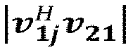
- the values of the coefficients of the precoding filters are determined from a linear combination of the first eigenvector of the SVDs performed on the two channel matrices and of the eigenvectors v 1 j and v 2 d , which respectively maximize v 1 j H v 21 and v 11 H v 2 j ′ .
- the figure 1 illustrates an example of a system according to the invention comprising a central node NC and two users T 1 , T 2 .
- a user T 1 , T 2 comprises an antenna network 10, 20 of K u antennas, each antenna network is connected to a transmission / reception system 11, 21, enabling reception to sample the signals received and to transmit them. switch to baseband and transmit to transpose the digital signal to be transmitted.
- This system is known to those skilled in the art and is based for example on analog receivers, allowing the transposition of the received signal into an intermediate frequency; analog transmitters, allowing the transposition of the signal to be transmitted to the transmission frequency, DUC / DDC converters (Digital Up-Converter, Digital Down-Converter) and analog / digital converters or digital / analog CAN / DAC.
- the transmission / reception system is connected to a processing device such as a signal processing processor and / or a programmable FPGA (Field Programmable Gate Array) circuit 12, 22 making it possible to implement the various processing operations according to the invention for each user.
- the processing device comprises a precoding module 13, 23 (digital filter on transmission) having the function of determining the coefficients to be used at the transmission level and a postcoding module 14, 24 (digital filter on reception) having the function of determining the coefficients to be used at the reception level.
- the antennas can be antennas performing the transmission / reception function.
- the antenna network can also include transmit antennas 10e, 20e and receive antennas 10r, 20r, separate and not shown for reasons of simplification.
- the central node NC comprises an antenna network 30 connected to a transmission / reception system 31 known to those skilled in the art and adapted in reception to sample the signals received and to pass them in baseband, and in transmission to transpose the digital signal to be transmitted.
- This system is known to those skilled in the art. It is based for example on analog receivers, allowing the transposition of the received signal into an intermediate frequency, analog transmitters, allowing the transposition of the signal to be emitted at the transmission frequency, DUC / DDC converters (Digital Up-Converter, Digital Down-Converter) and analog / digital or digital / analog CAN / DAC converters.
- the transmission / reception system is connected to a processing device 32 such as a signal processing processor and / or an FPGA allowing the various processing operations of the method according to the invention to be implemented for the central node.
- the processing device comprises a precoding module 33 (digital filter on transmission) having the function of determining the coefficients to be used at the level of the transmission and a postcoding module 34 (digital filter on reception) having the function of determine the coefficients to be used at the reception level.
- the network antenna of the central node can also include transmit antennas and receive antennas separate and not shown for reasons of simplification.
- a processor includes several functionalities, including in particular a synchronization function which allows synchronized transmission of signals by the different users.
- the transmit / receive system also allows synchronized transmission and reception of users.
- the local oscillators OLs are distributed on the different transmit / receive channels.
- the method will seek to globally optimize the reception of the useful signal on each of the antenna networks of the users: the useful signal s 1 ( n ) on the antenna network of the user T 1 and the useful signal s 2 ( n ) on the antenna array of user T 2 .
- the filters v i and w i ⁇ used respectively on transmission and on reception are calculated so as in particular to optimize, under certain constraints described below, the value of the signal to noise ratio or SINR at the output of processing for each user.
- the signals received by each user T 1 and T 2 , x 1 ( n ) and x 2 ( n ) are filtered on reception by each user (206, 207) by the filters w i ⁇ to obtain the signals y 1 ( n ) and y 2 ( n ), according to formula (4) above.
- the signals are then processed by the processes known to those skilled in the art (deinterlacing, decoding, etc.) to obtain the useful information.
- the idea implemented in the method according to the invention notably consists, for each user T i , in choosing the emission filter v i which will make it possible to maximize the energy emitted towards the user T i considered, while minimizing the impact of the signal thus transmitted for the reception of the other user (s).
- the method will seek to ensure that, on each reception network, the two channel vectors associated with the two users are orthogonal. In this way, a user who transmits will not or only slightly disturb the reception of the signal expected by another user.
- the method according to the invention also optimizes a criterion based on the SINR (Signal to Interference plus Noise Ratio) for each of the two users.
- a SINR criterion can be to maximize the minimum SNIR associated with each user or to maximize the sum of the SINRs, or to maximize the sum of the log 2 (1 + SINR) (which corresponds to maximizing the total throughput).
- the reception filters w 1 and w 2 which optimize reception are then equal to h 1 and h ' 2 respectively : the SINR, for example, is optimized, and the interference from the other user is naturally eliminated.
- the SINR for example
- SIMO reception algorithm it is possible to use the algorithm described in the applicant's patent US6243415 .
- the use of an algorithm comprising anti-jamming can prove to be interesting because it allows in particular to optimize the performances.
- the present invention relates in particular to the procedure for calculating transmission weights, which is independent of the procedure implemented on reception by each user.
- the emission weighting vectors v 1 and v 2 are then obtained from the couple ( ⁇ , ⁇ ) selected and using the formula (8).
- the values of the filters or vectors in emission v 1 and v 2 are then used respectively to make a beam formation in emission for the useful signals s 1 ( n ) and s 2 ( n ) intended for the two users, as it is illustrated in the figure 2 .
- each user T i arrives at the reception network of the central node with its own channel H i and there is only one reception network (the central node NC).
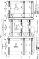
- a solution illustrated in the figure 4 consists in using to transmit the data, a frame comprising at least two types of slots: the MIMO_DATA slots and the MIMO_REF slots.
- the figure 4 gives an example of frame format used in the method according to the invention.
- Each 200 ms frame n is composed of a 100 ms DL subframe, for the link between the NC and the two users T 1 and T 2 , and a 100 ms UL subframe , for the link between the two users T 1 and T 2 and the central node NC.
- the frame lasts T ms.
- the channel matrix estimated at time t is therefore used less than T ms later.
- the principle therefore assumes good stationarity of the channel over this period.
- the slot MIMO_REF can be advantageously sent at the end of each sub-frame .
- This method makes it possible to transmit orthogonal sequences on the different transmission channels, as well as to facilitate channel estimation. It is used in both directions of the uplink, downlink.
- the figure 5 illustrates the sequencing of the steps implemented by the method according to the invention at the level of each user and at the level of the central node.
- the method applies in the case where the number of antennas in transmission is different from the number of antennas in reception on the different users.
- the invention applies when the modulation used for the transmission of useful data s i ( n ) is a serial modulation or a parallel modulation.
- the weights v i used in the two directions of the link can be applied frequency by frequency (in this case, it is necessary to estimate a channel matrix and to calculate the weightings at each frequency) or globally on the signal to be transmitted (only one set of weights applies to each frequency).
- the invention applies by using the strongest path (that which corresponds to the maximum energy received on all of the sensors for each user) to calculate the emission weights.
- Reception is carried out using a multisensor equalization algorithm known to those skilled in the art.
Landscapes
- Engineering & Computer Science (AREA)
- Computer Networks & Wireless Communication (AREA)
- Signal Processing (AREA)
- Radio Transmission System (AREA)
- Mobile Radio Communication Systems (AREA)
Claims (9)
- Verfahren zum räumlichen Multiplexen von Kommunikationsverbindungen des MIMO-(Multiple-Input Multiple-Output)-Typs für Abwärtsstrecke (Downlinks DL) und/oder für Aufwärtsübertragung (Uplinks UL) innerhalb eines Kommunikationsnetzwerks, das wenigstens einen zentralen Knotenpunkt NC umfasst, der ein Sende-/Empfangsnetz und wenigstens zwei Benutzer T 1 , T 2 umfasst, wobei jeder der beiden Benutzer mit einem Sende-/Empfangsnetzwerk ausgestattet ist, wobei das Verfahren die folgenden Schritte beinhaltet:• Bewirken, zum Berechnen der zum Senden (Vorcodierung) benutzten Koeffizienten, dass die beiden mit jedem der beiden Benutzer T 1 , T 2 assoziierten Kanalvektoren am Empfangsnetz-Zentralknotenpunkt (UL) oder am Empfangsnetz der Benutzer (DL) orthogonal sind, wobei das Verfahren gekennzeichnet ist durch:• Bestimmen der Koeffizienten beim Senden eines Signals für die Abwärtsstrecke (DL), gesendet vom Zentralknotenpunkt NC zu wenigstens jedem Benutzer Ti , der Ke Sendeantennen umfasst, wobei i = 1 und 2 ist, unter Ausführung wenigstens der folgenden Schritte:∘ Berechnen der jeweils mit den beiden Benutzern T 1 , T 2 assoziierten Vorcodierungsvektoren υ1 und υ2, durch Suchen derselben als eine lineare Kombination von Eigenvektoren, die mit den zwei größten Eigenwerten der Singulärwertzerlegung SVD der Kanalmatrizen H1 und H2 der Abwärtsstrecke assoziiert sind, wobei α und λ zwei komplexe Variablen sind:




 ∘ Auswählen desjenigen Paares aus den zwei Wertepaaren (α1, λ1) und (α 2, λ2), das eine Funktion der mit den beiden Benutzern assoziierten SNIR maximiert, definiert wie folgt:

- Verfahren nach Anspruch 1, dadurch gekennzeichnet, dass die zu maximierende Funktion Min(SNIR 1, SNIR2) oder der Summe SNIR1 + SNIR2 oder der Summe log2(1+SNIR 1) + log2(1+SNIR 2) entspricht.
- Verfahren nach Anspruch 1, dadurch gekennzeichnet, dass die Anzahl von Sendeantennen größer als zwei ist, und dadurch, dass es wenigstens einen oder mehrere Wiederholungsschritte beim Suchen der Vektoren υ 1(j) und υ 2(j'), gebildet auf der Basis der Eigenvektoren υ 11 und υ 21, assoziiert mit dem Höchstwert der Singulärwerte der SVD der zwei Kanalmatrizen der zwei Benutzer T 1 , T 2 und den Eigenvektoren υ 1j und υ 2 j,

- Verfahren nach Anspruch 1 oder 2, dadurch gekennzeichnet, dass für einen Ausbreitungskanal mit einer Dimension von gleich eins die Werte der Koeffizienten der Vorcodierungsfilter auf der Basis einer linearen Kombination aus dem ersten Eigenvektor von auf den beiden Kanalmatrizen durchgeführten SVD und den Eigenvektoren υ 1j und υ 2j bestimmt werden, die jeweils

- Verfahren nach einem der vorherigen Ansprüche, dadurch gekennzeichnet, dass im Falle der Abwärtsstrecke eines Benutzers zum Zentralknotenpunkt das Verfahren die folgenden Schritte beinhaltet:∘ Berechnen der Gewichtungen für die Sendung υ ul,1 und υ ul,2 des Signals in einem Raum, erzeugt durch die beiden ersten Eigenvektoren von den auf den Kanalmatrizen H ul,1 und H ul,2 durchgeführten Singulärwertzerlegungen SVD:


 ∘ Auswählen der Paare aus den Paaren (α, λ), die eine Funktion der mit den beiden Benutzern assoziierten beiden SNIR (SNIR 1, SNIR 2) maximieren:
- Verfahren nach Anspruch 5, dadurch gekennzeichnet, dass die Schritte durch Suchen der Vektoren υ ul,1(j) und υ ul,2(j'), gebildet auf der Basis der verschiedenen mit den beiden Kanalmatrizen assoziierten Eigenvektoren gemäß der folgenden Formel:


- Verfahren nach einem der vorherigen Ansprüche, dadurch gekennzeichnet, dass die Signale mit einem Frame-Format übertragen werden, das sich in einen Sub-Frame DL für die Abwärtsstrecke und einen Sub-Frame UL für die Aufwärtsübertragung untergliedert, und dadurch, dass jeder dieser beiden Sub-Frames untergliedert wird in:- einen MIMO_REF-Slot, auf dem die Lernsequenzen, die die Schätzung der mit jedem Benutzer assoziierten Kanalmatrizen ermöglichen, gesendet werden (501), wobei jede Antenne ihre eigene Referenzsequenz hat,- einen MIMO_DATA-Slot, auf dem die für jeden der Benutzer geschätzten Kanalmatrizen gesendet werden, um die Vorcodierungsvektoren (510) für die andere Richtung der Verbindung zu berechnen, unter Nutzung der in den Schritten von Anspruch 1 und Anspruch 2 für die Abwärtsstrecke (501) berechneten Gewichtungen und unter Nutzung der in den Schritten der Ansprüche 5 und 6 für die Aufwärtsübertragung (503) berechneten Gewichtungen,- N MIMO_DATA-Slots, konfiguriert zum Senden der Nutzdaten zum Zentralknotenpunkt NC, unter Nutzung der in den Schritten der Ansprüche 2 und 3 für die Abwärtsstrecke berechneten Gewichtungen und der in den Schritten gemäß Anspruch 5 und 6 für die Aufwärtsübertragung berechneten Gewichtungen.
- Verfahren nach Anspruch 7, dadurch gekennzeichnet, dass ein MIMO_REF-Slot aus einer Stufe besteht, auf der jede Sendeantenne ihre eigene Referenzsequenz sendet, erhalten auf der Basis einer auf einer Cazac-Sequenz bewirkten zyklischen Verschiebung.
- System zum räumlichen Multiplexen von Kommunikationsverbindungen des MIMO-(Multiple-Input Multiple Output)-Typs für Abwärtsstrecke (DL) und/oder für Aufwärtsübertragung (UL) innerhalb eines Kommunikationsnetzwerks, wobei das System wenigstens einen zentralen Knotenpunkt NC umfasst, der ein Sende-/Empfangsnetzwerk und wenigstens zwei Benutzer T 1 , T 2 umfasst, wobei jeder der beiden Benutzer mit einem Sende-/Empfangsnetzwerk (10, 20) ausgestattet ist, dadurch gekennzeichnet, dass:∘ jeder der beiden Benutzer mit einem Prozessor (12, 22) ausgestattet ist, konfiguriert zum Ausführen der Schritte des Verfahrens nach einem der Ansprüche 1 bis 8, wobei der Prozessor ein Vorcodierungsmodul (13, 23) mit der Funktion des Bestimmens der beim Senden zu benutzenden Koeffizienten und ein Nachcodierungsmodul (14, 24) mit der Funktion des Bestimmens der beim Empfangen zu benutzenden Koeffizienten umfasst,∘ der zentrale Knotenpunkt einen Prozessor (32) umfasst, konfiguriert zum Ausführen der Schritte des Verfahrens nach einem der Ansprüche 1 bis 8, wobei der Prozessor ein Vorcodierungsmodul (33), konfiguriert zum Bestimmen der beim Senden zu benutzenden Koeffizienten, und ein Nachcodierungsmodul (34) mit der Funktion des Bestimmens der beim Empfangen zu benutzenden Koeffizienten umfasst.
Priority Applications (1)
| Application Number | Priority Date | Filing Date | Title |
|---|---|---|---|
| PL18207698T PL3493420T3 (pl) | 2017-11-30 | 2018-11-22 | Sposób i system przestrzennego multipleksowania łączy w sieci komunikacyjnej |
Applications Claiming Priority (1)
| Application Number | Priority Date | Filing Date | Title |
|---|---|---|---|
| FR1701265A FR3074382B1 (fr) | 2017-11-30 | 2017-11-30 | Procede et systeme de multiplexage spatial de liaisons dans un reseau de communication |
Publications (2)
| Publication Number | Publication Date |
|---|---|
| EP3493420A1 EP3493420A1 (de) | 2019-06-05 |
| EP3493420B1 true EP3493420B1 (de) | 2020-07-01 |
Family
ID=61655816
Family Applications (1)
| Application Number | Title | Priority Date | Filing Date |
|---|---|---|---|
| EP18207698.4A Active EP3493420B1 (de) | 2017-11-30 | 2018-11-22 | Verfahren und system zum räumlichen multiplexen von verbindungen in einem kommunikationsnetz |
Country Status (4)
| Country | Link |
|---|---|
| EP (1) | EP3493420B1 (de) |
| ES (1) | ES2822210T3 (de) |
| FR (1) | FR3074382B1 (de) |
| PL (1) | PL3493420T3 (de) |
-
2017
- 2017-11-30 FR FR1701265A patent/FR3074382B1/fr not_active Expired - Fee Related
-
2018
- 2018-11-22 ES ES18207698T patent/ES2822210T3/es active Active
- 2018-11-22 PL PL18207698T patent/PL3493420T3/pl unknown
- 2018-11-22 EP EP18207698.4A patent/EP3493420B1/de active Active
Non-Patent Citations (1)
| Title |
|---|
| None * |
Also Published As
| Publication number | Publication date |
|---|---|
| FR3074382B1 (fr) | 2021-02-19 |
| FR3074382A1 (fr) | 2019-05-31 |
| EP3493420A1 (de) | 2019-06-05 |
| ES2822210T3 (es) | 2021-04-29 |
| PL3493420T3 (pl) | 2021-01-11 |
Similar Documents
| Publication | Publication Date | Title |
|---|---|---|
| US20250175291A1 (en) | Fractional cooperative multipoint network operation | |
| EP0846378B1 (de) | Verfahren und anordnung zur räumlichen multiplexierung/demultiplexierung von funksignalen in einem sdma-mobilfunksystem | |
| EP0735702B1 (de) | Verfahren und Vorrichtung zum Diversity-Empfang einer Basisstation in einem Mobilkommunikationssystem | |
| Song et al. | Improvement of time-reversal communications using adaptive channel equalizers | |
| EP2724476B1 (de) | Funkkommunikationsverfahren und vorrichtung für mehrbenutzerantennen | |
| EP0867079B1 (de) | Verfahren und anordnung zur entzerrung von mehrfachantennensignalen für mehrfachelementempfang in gegenwart von störungen und mehrwegausbreitungen | |
| EP3343784B1 (de) | Verfahren zur anwendung von entstörungsmassnahmen durch räumliche oder räumlich-zeitliche filterung in einem mehrweg-empfänger | |
| US11683712B2 (en) | Hybrid hierarchical parameter tracking for CSI estimation | |
| US20030214881A1 (en) | Underwater telemetry apparatus and method | |
| CN116865799B (zh) | 大规模mimo多卫星移动通信下行传输方法 | |
| FR3046311A1 (fr) | Procede de lutte anti-interference adaptatif dans un recepteur multi-voies | |
| Rudander et al. | Very-high-frequency single-input–multiple-output acoustic communication in shallow water | |
| Xu et al. | Joint channel estimation and passive beamforming for reconfigurable intelligent surface aided multi-user massive MIMO system | |
| EP3493420B1 (de) | Verfahren und system zum räumlichen multiplexen von verbindungen in einem kommunikationsnetz | |
| EP1265374B1 (de) | Verfahren und Vorrichtung zur Signalverarbeitung in einem Spreizspektrum Funkkommunikationsempfänger | |
| CN118826835B (zh) | 大规模mimo多卫星移动通信上行传输方法及系统 | |
| Aslandogan et al. | A Comprehensive Survey of Channel Estimation Techniques for OTFS in 6G and Beyond Wireless Networks | |
| EP1221792A1 (de) | Verfahren und Empfänger zur adaptiven Schätzung der Raum-Zeit-Parametern eines Kanal | |
| Porto et al. | Study of Iterative Detection and Decoding for Multiuser Systems and MMSE Refinements with Active or Passive RIS | |
| FR2738098A1 (fr) | Procede et dispositif de multiplexage spatial de signaux radio-electriques numeriques echanges dans des radiocommunications cellulaires | |
| Kida et al. | The effects of interferences on time reversal MIMO: an evaluation of multipath and co-channel interference | |
| Rashid | Channel estimation in multi-user massive MIMO systems by expectation propagation based algorithms | |
| FR2802043A1 (fr) | Dispositifs d'estimation de canal radio et de demodulation | |
| Khichar | Convolutional neural network based wireless channel estimation and impact of estimation on hybrid precoding | |
| WO2019039980A1 (en) | BEAM FORMATION WITH QUADRATIC CALCULATION COMPLEXITY IN THE ANTENNA NETWORK SIZE |
Legal Events
| Date | Code | Title | Description |
|---|---|---|---|
| PUAI | Public reference made under article 153(3) epc to a published international application that has entered the european phase |
Free format text: ORIGINAL CODE: 0009012 |
|
| STAA | Information on the status of an ep patent application or granted ep patent |
Free format text: STATUS: THE APPLICATION HAS BEEN PUBLISHED |
|
| AK | Designated contracting states |
Kind code of ref document: A1 Designated state(s): AL AT BE BG CH CY CZ DE DK EE ES FI FR GB GR HR HU IE IS IT LI LT LU LV MC MK MT NL NO PL PT RO RS SE SI SK SM TR |
|
| AX | Request for extension of the european patent |
Extension state: BA ME |
|
| STAA | Information on the status of an ep patent application or granted ep patent |
Free format text: STATUS: REQUEST FOR EXAMINATION WAS MADE |
|
| 17P | Request for examination filed |
Effective date: 20191203 |
|
| RBV | Designated contracting states (corrected) |
Designated state(s): AL AT BE BG CH CY CZ DE DK EE ES FI FR GB GR HR HU IE IS IT LI LT LU LV MC MK MT NL NO PL PT RO RS SE SI SK SM TR |
|
| GRAP | Despatch of communication of intention to grant a patent |
Free format text: ORIGINAL CODE: EPIDOSNIGR1 |
|
| STAA | Information on the status of an ep patent application or granted ep patent |
Free format text: STATUS: GRANT OF PATENT IS INTENDED |
|
| RIC1 | Information provided on ipc code assigned before grant |
Ipc: H04B 7/0452 20170101AFI20200108BHEP Ipc: H04B 7/06 20060101ALI20200108BHEP |
|
| INTG | Intention to grant announced |
Effective date: 20200211 |
|
| GRAS | Grant fee paid |
Free format text: ORIGINAL CODE: EPIDOSNIGR3 |
|
| GRAA | (expected) grant |
Free format text: ORIGINAL CODE: 0009210 |
|
| STAA | Information on the status of an ep patent application or granted ep patent |
Free format text: STATUS: THE PATENT HAS BEEN GRANTED |
|
| AK | Designated contracting states |
Kind code of ref document: B1 Designated state(s): AL AT BE BG CH CY CZ DE DK EE ES FI FR GB GR HR HU IE IS IT LI LT LU LV MC MK MT NL NO PL PT RO RS SE SI SK SM TR |
|
| REG | Reference to a national code |
Ref country code: CH Ref legal event code: EP Ref country code: AT Ref legal event code: REF Ref document number: 1287157 Country of ref document: AT Kind code of ref document: T Effective date: 20200715 |
|
| REG | Reference to a national code |
Ref country code: IE Ref legal event code: FG4D Free format text: LANGUAGE OF EP DOCUMENT: FRENCH |
|
| REG | Reference to a national code |
Ref country code: DE Ref legal event code: R096 Ref document number: 602018005715 Country of ref document: DE |
|
| REG | Reference to a national code |
Ref country code: FI Ref legal event code: FGE |
|
| REG | Reference to a national code |
Ref country code: LT Ref legal event code: MG4D |
|
| PG25 | Lapsed in a contracting state [announced via postgrant information from national office to epo] |
Ref country code: BG Free format text: LAPSE BECAUSE OF FAILURE TO SUBMIT A TRANSLATION OF THE DESCRIPTION OR TO PAY THE FEE WITHIN THE PRESCRIBED TIME-LIMIT Effective date: 20201001 |
|
| REG | Reference to a national code |
Ref country code: NL Ref legal event code: MP Effective date: 20200701 |
|
| REG | Reference to a national code |
Ref country code: AT Ref legal event code: MK05 Ref document number: 1287157 Country of ref document: AT Kind code of ref document: T Effective date: 20200701 |
|
| PG25 | Lapsed in a contracting state [announced via postgrant information from national office to epo] |
Ref country code: GR Free format text: LAPSE BECAUSE OF FAILURE TO SUBMIT A TRANSLATION OF THE DESCRIPTION OR TO PAY THE FEE WITHIN THE PRESCRIBED TIME-LIMIT Effective date: 20201002 Ref country code: AT Free format text: LAPSE BECAUSE OF FAILURE TO SUBMIT A TRANSLATION OF THE DESCRIPTION OR TO PAY THE FEE WITHIN THE PRESCRIBED TIME-LIMIT Effective date: 20200701 Ref country code: PT Free format text: LAPSE BECAUSE OF FAILURE TO SUBMIT A TRANSLATION OF THE DESCRIPTION OR TO PAY THE FEE WITHIN THE PRESCRIBED TIME-LIMIT Effective date: 20201102 Ref country code: SE Free format text: LAPSE BECAUSE OF FAILURE TO SUBMIT A TRANSLATION OF THE DESCRIPTION OR TO PAY THE FEE WITHIN THE PRESCRIBED TIME-LIMIT Effective date: 20200701 Ref country code: HR Free format text: LAPSE BECAUSE OF FAILURE TO SUBMIT A TRANSLATION OF THE DESCRIPTION OR TO PAY THE FEE WITHIN THE PRESCRIBED TIME-LIMIT Effective date: 20200701 Ref country code: LT Free format text: LAPSE BECAUSE OF FAILURE TO SUBMIT A TRANSLATION OF THE DESCRIPTION OR TO PAY THE FEE WITHIN THE PRESCRIBED TIME-LIMIT Effective date: 20200701 Ref country code: CZ Free format text: LAPSE BECAUSE OF FAILURE TO SUBMIT A TRANSLATION OF THE DESCRIPTION OR TO PAY THE FEE WITHIN THE PRESCRIBED TIME-LIMIT Effective date: 20200701 Ref country code: NO Free format text: LAPSE BECAUSE OF FAILURE TO SUBMIT A TRANSLATION OF THE DESCRIPTION OR TO PAY THE FEE WITHIN THE PRESCRIBED TIME-LIMIT Effective date: 20201001 |
|
| PG25 | Lapsed in a contracting state [announced via postgrant information from national office to epo] |
Ref country code: RS Free format text: LAPSE BECAUSE OF FAILURE TO SUBMIT A TRANSLATION OF THE DESCRIPTION OR TO PAY THE FEE WITHIN THE PRESCRIBED TIME-LIMIT Effective date: 20200701 Ref country code: LV Free format text: LAPSE BECAUSE OF FAILURE TO SUBMIT A TRANSLATION OF THE DESCRIPTION OR TO PAY THE FEE WITHIN THE PRESCRIBED TIME-LIMIT Effective date: 20200701 Ref country code: IS Free format text: LAPSE BECAUSE OF FAILURE TO SUBMIT A TRANSLATION OF THE DESCRIPTION OR TO PAY THE FEE WITHIN THE PRESCRIBED TIME-LIMIT Effective date: 20201101 |
|
| PG25 | Lapsed in a contracting state [announced via postgrant information from national office to epo] |
Ref country code: NL Free format text: LAPSE BECAUSE OF FAILURE TO SUBMIT A TRANSLATION OF THE DESCRIPTION OR TO PAY THE FEE WITHIN THE PRESCRIBED TIME-LIMIT Effective date: 20200701 |
|
| REG | Reference to a national code |
Ref country code: DE Ref legal event code: R097 Ref document number: 602018005715 Country of ref document: DE |
|
| PG25 | Lapsed in a contracting state [announced via postgrant information from national office to epo] |
Ref country code: SM Free format text: LAPSE BECAUSE OF FAILURE TO SUBMIT A TRANSLATION OF THE DESCRIPTION OR TO PAY THE FEE WITHIN THE PRESCRIBED TIME-LIMIT Effective date: 20200701 Ref country code: EE Free format text: LAPSE BECAUSE OF FAILURE TO SUBMIT A TRANSLATION OF THE DESCRIPTION OR TO PAY THE FEE WITHIN THE PRESCRIBED TIME-LIMIT Effective date: 20200701 Ref country code: RO Free format text: LAPSE BECAUSE OF FAILURE TO SUBMIT A TRANSLATION OF THE DESCRIPTION OR TO PAY THE FEE WITHIN THE PRESCRIBED TIME-LIMIT Effective date: 20200701 Ref country code: DK Free format text: LAPSE BECAUSE OF FAILURE TO SUBMIT A TRANSLATION OF THE DESCRIPTION OR TO PAY THE FEE WITHIN THE PRESCRIBED TIME-LIMIT Effective date: 20200701 |
|
| PLBE | No opposition filed within time limit |
Free format text: ORIGINAL CODE: 0009261 |
|
| STAA | Information on the status of an ep patent application or granted ep patent |
Free format text: STATUS: NO OPPOSITION FILED WITHIN TIME LIMIT |
|
| PG25 | Lapsed in a contracting state [announced via postgrant information from national office to epo] |
Ref country code: AL Free format text: LAPSE BECAUSE OF FAILURE TO SUBMIT A TRANSLATION OF THE DESCRIPTION OR TO PAY THE FEE WITHIN THE PRESCRIBED TIME-LIMIT Effective date: 20200701 |
|
| 26N | No opposition filed |
Effective date: 20210406 |
|
| PG25 | Lapsed in a contracting state [announced via postgrant information from national office to epo] |
Ref country code: SK Free format text: LAPSE BECAUSE OF FAILURE TO SUBMIT A TRANSLATION OF THE DESCRIPTION OR TO PAY THE FEE WITHIN THE PRESCRIBED TIME-LIMIT Effective date: 20200701 Ref country code: MC Free format text: LAPSE BECAUSE OF FAILURE TO SUBMIT A TRANSLATION OF THE DESCRIPTION OR TO PAY THE FEE WITHIN THE PRESCRIBED TIME-LIMIT Effective date: 20200701 |
|
| PG25 | Lapsed in a contracting state [announced via postgrant information from national office to epo] |
Ref country code: LU Free format text: LAPSE BECAUSE OF NON-PAYMENT OF DUE FEES Effective date: 20201122 |
|
| REG | Reference to a national code |
Ref country code: BE Ref legal event code: MM Effective date: 20201130 |
|
| PG25 | Lapsed in a contracting state [announced via postgrant information from national office to epo] |
Ref country code: SI Free format text: LAPSE BECAUSE OF FAILURE TO SUBMIT A TRANSLATION OF THE DESCRIPTION OR TO PAY THE FEE WITHIN THE PRESCRIBED TIME-LIMIT Effective date: 20200701 |
|
| PG25 | Lapsed in a contracting state [announced via postgrant information from national office to epo] |
Ref country code: IE Free format text: LAPSE BECAUSE OF NON-PAYMENT OF DUE FEES Effective date: 20201122 |
|
| PG25 | Lapsed in a contracting state [announced via postgrant information from national office to epo] |
Ref country code: TR Free format text: LAPSE BECAUSE OF FAILURE TO SUBMIT A TRANSLATION OF THE DESCRIPTION OR TO PAY THE FEE WITHIN THE PRESCRIBED TIME-LIMIT Effective date: 20200701 Ref country code: MT Free format text: LAPSE BECAUSE OF FAILURE TO SUBMIT A TRANSLATION OF THE DESCRIPTION OR TO PAY THE FEE WITHIN THE PRESCRIBED TIME-LIMIT Effective date: 20200701 Ref country code: CY Free format text: LAPSE BECAUSE OF FAILURE TO SUBMIT A TRANSLATION OF THE DESCRIPTION OR TO PAY THE FEE WITHIN THE PRESCRIBED TIME-LIMIT Effective date: 20200701 |
|
| PG25 | Lapsed in a contracting state [announced via postgrant information from national office to epo] |
Ref country code: MK Free format text: LAPSE BECAUSE OF FAILURE TO SUBMIT A TRANSLATION OF THE DESCRIPTION OR TO PAY THE FEE WITHIN THE PRESCRIBED TIME-LIMIT Effective date: 20200701 |
|
| REG | Reference to a national code |
Ref country code: CH Ref legal event code: PL |
|
| PG25 | Lapsed in a contracting state [announced via postgrant information from national office to epo] |
Ref country code: BE Free format text: LAPSE BECAUSE OF NON-PAYMENT OF DUE FEES Effective date: 20201130 |
|
| PG25 | Lapsed in a contracting state [announced via postgrant information from national office to epo] |
Ref country code: LI Free format text: LAPSE BECAUSE OF NON-PAYMENT OF DUE FEES Effective date: 20211130 Ref country code: CH Free format text: LAPSE BECAUSE OF NON-PAYMENT OF DUE FEES Effective date: 20211130 |
|
| P01 | Opt-out of the competence of the unified patent court (upc) registered |
Effective date: 20230517 |
|
| GBPC | Gb: european patent ceased through non-payment of renewal fee |
Effective date: 20221122 |
|
| PG25 | Lapsed in a contracting state [announced via postgrant information from national office to epo] |
Ref country code: GB Free format text: LAPSE BECAUSE OF NON-PAYMENT OF DUE FEES Effective date: 20221122 |
|
| PGFP | Annual fee paid to national office [announced via postgrant information from national office to epo] |
Ref country code: DE Payment date: 20251014 Year of fee payment: 8 |
|
| PGFP | Annual fee paid to national office [announced via postgrant information from national office to epo] |
Ref country code: FI Payment date: 20251113 Year of fee payment: 8 Ref country code: IT Payment date: 20251030 Year of fee payment: 8 |
|
| PGFP | Annual fee paid to national office [announced via postgrant information from national office to epo] |
Ref country code: FR Payment date: 20251023 Year of fee payment: 8 |
|
| PGFP | Annual fee paid to national office [announced via postgrant information from national office to epo] |
Ref country code: PL Payment date: 20251022 Year of fee payment: 8 |
|
| PGFP | Annual fee paid to national office [announced via postgrant information from national office to epo] |
Ref country code: ES Payment date: 20251210 Year of fee payment: 8 |