EP3493929B1 - Procédé de coulée continue - Google Patents
Procédé de coulée continue Download PDFInfo
- Publication number
- EP3493929B1 EP3493929B1 EP18739653.6A EP18739653A EP3493929B1 EP 3493929 B1 EP3493929 B1 EP 3493929B1 EP 18739653 A EP18739653 A EP 18739653A EP 3493929 B1 EP3493929 B1 EP 3493929B1
- Authority
- EP
- European Patent Office
- Prior art keywords
- product
- sides
- crystallizer
- productivity
- casting
- Prior art date
- Legal status (The legal status is an assumption and is not a legal conclusion. Google has not performed a legal analysis and makes no representation as to the accuracy of the status listed.)
- Active
Links
Images

Classifications
-
- B—PERFORMING OPERATIONS; TRANSPORTING
- B22—CASTING; POWDER METALLURGY
- B22D—CASTING OF METALS; CASTING OF OTHER SUBSTANCES BY THE SAME PROCESSES OR DEVICES
- B22D11/00—Continuous casting of metals, i.e. casting in indefinite lengths
- B22D11/16—Controlling or regulating processes or operations
- B22D11/18—Controlling or regulating processes or operations for pouring
-
- B—PERFORMING OPERATIONS; TRANSPORTING
- B22—CASTING; POWDER METALLURGY
- B22D—CASTING OF METALS; CASTING OF OTHER SUBSTANCES BY THE SAME PROCESSES OR DEVICES
- B22D11/00—Continuous casting of metals, i.e. casting in indefinite lengths
- B22D11/009—Continuous casting of metals, i.e. casting in indefinite lengths of work of special cross-section, e.g. I-beams, U-profiles
-
- B—PERFORMING OPERATIONS; TRANSPORTING
- B22—CASTING; POWDER METALLURGY
- B22D—CASTING OF METALS; CASTING OF OTHER SUBSTANCES BY THE SAME PROCESSES OR DEVICES
- B22D11/00—Continuous casting of metals, i.e. casting in indefinite lengths
- B22D11/04—Continuous casting of metals, i.e. casting in indefinite lengths into open-ended moulds
- B22D11/0406—Moulds with special profile
-
- B—PERFORMING OPERATIONS; TRANSPORTING
- B22—CASTING; POWDER METALLURGY
- B22D—CASTING OF METALS; CASTING OF OTHER SUBSTANCES BY THE SAME PROCESSES OR DEVICES
- B22D11/00—Continuous casting of metals, i.e. casting in indefinite lengths
- B22D11/12—Accessories for subsequent treating or working cast stock in situ
- B22D11/1206—Accessories for subsequent treating or working cast stock in situ for plastic shaping of strands
-
- B—PERFORMING OPERATIONS; TRANSPORTING
- B22—CASTING; POWDER METALLURGY
- B22D—CASTING OF METALS; CASTING OF OTHER SUBSTANCES BY THE SAME PROCESSES OR DEVICES
- B22D11/00—Continuous casting of metals, i.e. casting in indefinite lengths
- B22D11/12—Accessories for subsequent treating or working cast stock in situ
- B22D11/124—Accessories for subsequent treating or working cast stock in situ for cooling
- B22D11/1246—Nozzles; Spray heads
-
- B—PERFORMING OPERATIONS; TRANSPORTING
- B22—CASTING; POWDER METALLURGY
- B22D—CASTING OF METALS; CASTING OF OTHER SUBSTANCES BY THE SAME PROCESSES OR DEVICES
- B22D11/00—Continuous casting of metals, i.e. casting in indefinite lengths
- B22D11/12—Accessories for subsequent treating or working cast stock in situ
- B22D11/128—Accessories for subsequent treating or working cast stock in situ for removing
- B22D11/1282—Vertical casting and curving the cast stock to the horizontal
-
- B—PERFORMING OPERATIONS; TRANSPORTING
- B22—CASTING; POWDER METALLURGY
- B22D—CASTING OF METALS; CASTING OF OTHER SUBSTANCES BY THE SAME PROCESSES OR DEVICES
- B22D11/00—Continuous casting of metals, i.e. casting in indefinite lengths
- B22D11/14—Plants for continuous casting
- B22D11/142—Plants for continuous casting for curved casting
Definitions
- the present invention concerns a continuous casting method and a corresponding apparatus.
- the present invention is applied to apparatuses and methods for the curved continuous casting of metal products.
- the present invention is also applied to a method and an apparatus for casting billets or blooms having a polygonal shape, for example square, hexagonal or octagonal, although a different number of sides is not excluded, for example pentagonal, heptagonal, etc.
- a casting apparatus according to the state of the art is shown, in which the crystallizer 111, for casting billets or blooms, is defined by a tubular body 112, in which the liquid metal M cools. It is also known to provide that the tubular body 112 is provided, in the thickness of its walls, and for at least part of the longitudinal development, with a plurality of cooling channels 117 through which a cooling liquid flows, which indirectly subtracts heat from the liquid product by means of the heat exchange that occurs between it and the walls in contact with the coolant.
- the cooling inside the crystallizer is called primary cooling.
- the product P starts to solidify externally, determining the formation of a surface skin 113 that becomes thicker as the product P approaches the exit from the crystallizer 111.
- the formation of the thickness of the skin 113 is influenced by the casting speed and therefore by productivity.
- the casting speed determines the permanence of the skin 113 in the crystallizer 111.
- the external surfaces of the metal product are normally supported, along the casting line, by special roller guide systems, or mobile containing sectors 114, substantially parallel to the faces of the product P which they have to support.
- Each containing sector 114 is normally provided with a plurality of rollers 116 located so as to laterally surround the lateral section of the product P which is cast, so as to define the containment of the latter.
- the thickness of the skin 113 in formation must also be increased by means of a direct cooling of the product P, called secondary cooling.
- the secondary cooling can take place either by means of said mobile sectors 114, provided with an internal cooling system, or by means of sprays 115, using normal or nebulized water, accompanying the product P until the inside is completely solidified in the so-called kissing point K, that is, the point along the casting line where the cross section of the cast product P is completely solidified.
- the containing sectors 114 therefore constitute the external skeleton which allows the product P to descend along the casting line, to cool down and to pass from a vertical position to a horizontal position, following the theoretical casting radius of curvature.
- the containing sectors 114 moreover, accompany the cast product P toward the straightening units which draw the cast product P out of the casting apparatus.
- support and bending rollers 118 are normally support and bending rollers 118 provided to support and curve the metallic product P from the vertical condition to the horizontal condition.
- the support and bending rollers 118 are located distanced along the casting line and alternately one on the intrados side and the next on the extrados side of the casting line.
- the mobile containing sectors 114 are necessary not only to cool the product P, but also to support the faces defining the product itself.
- the skins forming the product P are characterized by having a rather low thickness, and are subject to the phenomenon of "bulging", that is, a swelling effect caused by the ferrostatic pressure which thrusts toward the outside the fraction of liquid product, swelling the walls of solidified skin.
- the alignment of the containing sectors 114 in fact, has to follow the natural shrinkage of the skin of the product P, which takes place as a consequence of cooling. If, for some reason, the contact between the skin and the containing sectors 114 were to occur in an inappropriate way, there are concrete possibilities that the skin can be pinched or torn, thus causing potential break-outs.
- the maintenance made necessary by the containing sectors 114 is quite high, given that each face of the product P is supported by a containing sector 114 for almost the entire casting curve. Furthermore, the alignment must be done manually by operators outside the casting line, so great expertise is required during assembly in the work place, given that the containing sectors 114 often become misaligned during this step.
- One purpose of the present invention is to perfect a continuous casting method which is efficient and allows to achieve high productivity.
- Another purpose of the present invention is to perfect a continuous casting method which allows to increase the quality of the cast products.
- the Applicant has devised, tested and embodied the present invention to overcome the shortcomings of the state of the art and to obtain these and other purposes and advantages.
- the present invention concerns a method for the continuous casting of a product, chosen from billets or blooms, along a curved casting line.
- the method provides to cast a liquid metal in a crystallizer that is provided with a tubular cavity having a polygonal cross section defined by a determinate number of sides.
- the product exiting from the crystallizer is curved along the casting line by support and curving rollers and without the aid of lateral containing sectors of the cross section of the product downstream of the crystallizer.
- the method comprises setting a productivity of the casting line, and therefore a casting speed, chosen inside a predefined work field and as a function of the number of sides, and supplying the crystallizer having a number of sides determined so as to obtain the set productivity, and so that the product, at exit from the crystallizer, has at least a minimum thickness of solidified skin and so that the deformation of the skin is limited below a threshold value.
- the productivity is set so that it is less than or equal to the minimum value between the first maximum productivity and the second maximum productivity.
- the method according to the invention therefore allows to increase the productivity of a casting line limiting the management costs compared to known solutions, avoiding having to use containing sectors downstream of the crystallizer and therefore limiting the problems of maintenance and control connected thereto.
- the product at exit from the crystallizer has at least a minimum thickness of solidified skin and the deformation of the skin is limited below a threshold value, or is not subjected to phenomena of bulging.
- the present invention therefore, makes it possible to identify the maximum productivity (casting speed) of an apparatus for continuous casting so that the product, at exit from the crystallizer, has a "bulging" value below a predetermined limit value and a skin thickness value higher than another predetermined limit value.
- a casting layout regulated according to the method of the present invention, is optimal for "micromill" plants, in which there is a single casting line which feeds a rolling mill directly in endless mode.
- Embodiments of the present invention also concern a continuous casting apparatus comprising a curved casting line provided with a crystallizer having a tubular cavity with a polygonal cross section defined by a determinate number of sides.
- rollers to support and curve the product are installed along said casting line and there are no sectors for the lateral containment of the cross section of the product.
- Embodiments of the present invention concern a method for the continuous casting of a product P along a curved casting line 18.
- curved casting line 18 we intend to comprise both an apparatus that develops along a completely curved casting line, and also a vertical casting line in the initial segment and subsequently curved.
- an apparatus for continuous casting is indicated in its entirety by the reference number 10 and is suitable to cast a metal product P selected in a group comprising billets and blooms.
- the apparatus 10 comprises a crystallizer 11 having a tubular shape and provided with a tubular cavity 12 in which liquid metal M is discharged during use.
- the crystallizer 11 allows to solidify the liquid metal M, generating a solidified external skin 13.
- the skin 13 has a thickness "t" which progressively increases from the solidification zone, inside the crystallizer 11, until reaching a point, called “kissing point K", usually outside the crystallizer 11, in which the product P is completely solidified.
- the tubular cavity 12 has a polygonal cross section shape determined by a determinate number of sides "n".
- the cross section of the tubular cavity 12 has a square, hexagonal, octagonal, or decagonal shape.
- cross section can have a different number of sides, for example triangular, pentagonal or heptagonal.
- Embodiments of the present invention can provide that the tubular cavity 12 is defined by a plurality of walls 14 defining the sides of the crystallizer 11.
- the walls 14 of the crystallizer 11 all have the same sizes. In this way the skin 13 that is formed during casting has a conformation substantially mating with that of the casting cavity 12, and the sides of the skin 13, having the same sizes, will be subjected to the same stresses, for example to the same ferrostatic pressure.
- the walls 14 have different sizes or width.
- the crystallizer 11 is provided with a first end 15 through which the liquid metal M is fed, and a second end 16, opposite the first end 15, through which the partly solidified product P is discharged from the crystallizer 11.
- the crystallizer 11 is provided with cooling means 17 configured to cool the crystallizer 11 which, in turn, exerts a cooling action on the liquid metal M and allows the formation of the skin 13.
- support and curving rollers 19 configured to support and curve the product P along the casting line 18.
- the support and curving rollers 19 are installed reciprocally distanced along the casting line and are located in succession one on the intrados side and the other on the extrados side of the casting line 18 itself.
- the support and curving rollers 19 can be disposed only on the extrados and intrados side of the casting line 18.
- the support and curving rollers 19 are installed directly downstream of the exit from the crystallizer 11.
- the product P exiting from the crystallizer 11 is therefore directly accompanied and curved along the casting line by the support and curving rollers 19 and without the aid of lateral containing sectors of the cross section of the product P.
- lateral containing sectors of the cross section we mean containing elements which are located facing each other to peripherally surround the sides of the cross section of the cast product P.
- the casting apparatus 10 downstream of the support and curving rollers 19, the casting apparatus 10 comprises straightening and/or drawing units 20 configured to straighten the product P and/or possibly carry out an action to compress it.
- the straightening and/or drawing unit 20 determines a casting speed V c of the product itself along the casting line 18.
- the straightening and/or drawing unit 20 can be provided with rollers 22 having the function of straightening, compression, and/or drawing.
- the product P exiting from the crystallizer 11 is supported and guided, or curved, only by the action of the support and curving rollers 19, until it enters the straightening and/or drawing unit 20.
- the support and curving rollers 19 can be provided with cooling devices, such as internal cooling channels, to cool both the support and curving rollers 19 themselves, and the skin 13 of the product P.
- the apparatus 10 can also comprise cooling means 21, for example nozzles, to deliver nebulized water, so as to further cool the product P.
- cooling means 21 for example nozzles, to deliver nebulized water, so as to further cool the product P.
- the method according to the present invention provides to cast the liquid metal M into the crystallizer 11.
- the product P exiting from the crystallizer 11 is curved along the casting line by means of the support and curving rollers 19 and without the aid of lateral containing sectors of the cross section of the product P.
- the method before starting the casting, the method comprises setting a productivity P r of the casting line 18 which is selected inside a predefined work field and a function of the number of sides n of the tubular cavity 12, or of the crystallizer 11.
- the method provides to supply the crystallizer 11 having a number of sides n determined so as to obtain, or achieve, said preset productivity P r and so that the product P, at exit from the crystallizer 11, has at least a minimum thickness t min of solidified skin 13 and so that the deformation of the skin 13 is limited below a threshold value.
- the choice of the crystallizer 11, according to the present invention allows to prevent the occurrence of deformations of the skin 13 such as to cause any damage thereto.
- the deformations of the skin 13 must be such as not to exceed at least the breaking or yield point of the skin 13 itself.
- the skin 13 of the product P is in fact subjected to a phenomenon of deformation, or bulging.
- the phenomenon of bulging is caused by the ferrostatic pressure which the liquid metal M exerts on the skin 13 of the product P and which causes a maximum deformation or deflection of the skin 13.
- the work field is delimited by a first achievable maximum productivity P rmaxb determined in such a way as to prevent the skin 13 from deforming above said threshold, or from being subject to the phenomenon of bulging, and a second maximum productivity achievable P rmaxt determined so that the skin 13 has at least the minimum thickness t min .
- the achievable maximum productivity P rmaxb is determined with profiles of every polygonal shape, beyond which unsustainable problems of bulging arise.
- P rmaxb 3,6 ⁇ ⁇ ⁇ A ⁇ V cmaxb
- the fixed area number represents the ratio between the area of the polygon and the area of a square which has for its side the side of the polygon.
- Each regular polygon has its own fixed area number, summarized below: Regular polygon f Triangle 0.433 Square 1 Pentagon 1.720 Hexagon 2.598 Heptagon 3.634 Octagon 4.828 Nonagon 6.182 Decagon 7.694
- productivity P r of the casting line 18 must be less than or, at most, equal to the P rmaxb defined above, that is, P r ⁇ P rmaxb must be obtained.
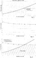
- Fig. 4 shows the maximum productivity P rmaxb associated with products P having from a minimum of 4 sides to a maximum of 10, using the following data by way of example: Description Symbol Value Unit Density of product P ⁇ 7750 kg/m 3 Maximum constant bulging K 0.044 (m 3 /s) 0.5
- a productivity P r of 140 t/h can be achieved, regardless of the size of the side W, with a crystallizer 11 of hexagonal shape at full power, or with an octagonal shape at medium power.
- the shape of the polygon of the casting cavity 12 is selected from square, hexagon and octagon, that is, a polygon having a number of sides equal to four, or six, or eight.
- the thickness t of the skin 13 of the product P exiting from the crystallizer 11 is directly linked to the casting speed V c ; in fact, through the solidification constant K S of the product P, a higher casting speed V c determines a lesser thickness of the skin 13 of the product P and vice versa.
- the thickness t of the skin 13 of the product P exiting from the crystallizer 11 must therefore be greater than or equal to a minimum safety thickness t min .
- the minimum safety thickness t min can generally be between 6mm and 10mm, and the present invention suggests preferably between 7mm and 9mm, even more preferably about 8mm.
- the limit in terms of minimum thickness t min entails the need not to exceed a determinate value of casting speed V cmaxt .
- the side of the polygon W can be expressed as a function of the diameter D of the circumference inscribed in the polygon which describes the section of the product P, since for the purposes of cooling the edges are less problematic, as they cool more quickly.
- the maximum productivity with the limit in terms of minimum thickness besides being a function of the number of sides n, also depends on t min and D.
- the productivity P r of the casting line estimated taking into consideration a limit thickness of the skin, must therefore be less than or equal to the P rmaxt calculated above, or P r ⁇ P rmaxt .
- Fig. 5 represents the maximum productivity P rmaxt associated with products P having from a minimum of 4 sides to a maximum of 10, using the following data by way of example: Description Symbol Value Unit Density of product P ⁇ 7750 kg/m 3 Solidification constant K S 3.87E-03 m/s 0.5 Inscribed diameter D 0.22 m Minimum thickness t min 0.008 m
- the curve which describes the maximum productivity P rmaxt has an asymptotic development, being essentially a function of the expression n * tan( ⁇ /n) which for n tending to infinity assumes the constant value ⁇ .
- This development means that, beyond a certain n, the maximum productivity P rmaxt achievable remains constant, so that a further increase in the number of sides n does not lead to any advantage.
- the casting line 18 can have a productivity P r greater than or equal to 60 t/h.
- the method provides that the productivity P r set in the casting line, for the specific number of sides n of the crystallizer 11 selected, is lower than or equal to the minimum value between the first maximum productivity (P rmaxb ) and the second maximum productivity (P rmaxt ).
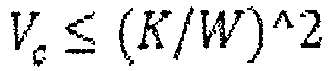
- the crystallizer 11 has a number of sides n lower than the optimum number of sides n ott , it is provided to cast the product P with a casting speed expressed by the relation: V c ⁇ K / W ⁇ 2
Landscapes
- Engineering & Computer Science (AREA)
- Mechanical Engineering (AREA)
- Continuous Casting (AREA)
- Molds, Cores, And Manufacturing Methods Thereof (AREA)
Claims (8)
- Méthode de coulée continue d'un produit (P), choisi parmi les billettes ou les blooms, le long d'une ligne de coulée incurvée (18), ladite méthode consistant à couler un métal liquide (M) dans un cristallisateur (11) pourvu d'une cavité tubulaire (12) ayant une section transversale polygonale définie par un nombre déterminé de côtés (n), caractérisée en ce que ledit produit (P) sortant dudit cristallisateur (11) est incurvé le long de ladite ligne de coulée (18) par des rouleaux de support et d'incurvation (19) et sans l'aide de secteurs de confinement latéraux de la section transversale dudit produit (P), en ce que ladite méthode comprend la détermination d'une productivité (Pr) de ladite ligne de coulée (18) choisie à l'intérieur d'un champ de travail délimité par une première productivité maximum atteignable (Prmaxb), et par une seconde productivité maximum atteignable (Prmaxt), ladite première productivité maximum atteignable (Prmaxb) étant définie par l'expression :
 p : est la densité du métal solide,K : est une constante comprise entre 0,04 et 0,05 ; etn : est le nombre de côtés dudit polygone de la cavité tubulaire (12) ;et ladite seconde productivité maximum atteignable (Prmaxt) étant définie par l'expression :dans laquelle
 p : est la densité du métal solide ;D : est une taille de la section transversale dudit produit (P) ;Ks : est une constante de solidification déterminée en fonction du matériau dudit métal liquide (M) ;tmin : est une épaisseur minimum prédéterminée dudit produit (P) ;n : est le nombre de côtés dudit polygone de la cavité tubulaire (12) ;en ce que ladite productivité (Pr) est définie de sorte qu'elle soit inférieure ou égale à la valeur minimum entre ladite première productivité maximum (Prmaxb) et ladite seconde productivité maximum (Prmaxt), et en ce que ledit méthode comprend l'alimentation dudit cristallisateur (11) ayant un nombre de côtés (n) déterminé de manière à obtenir ladite productivité définie (Pr).
 - Méthode selon la revendication 1, caractérisée en ce qu'elle consiste à déterminer un nombre optimum de côtés (nott) propre à optimiser ladite productivité (Pr), ledit nombre optimum de côtés (nott) étant déterminé par l'expression :
 int : représente le nombre entier approché par défaut de l'expression comprise entre parenthèses ;K : est une constante comprise entre 0,04 et 0,05 ;KS : est une constante de solidification déterminée en fonction du matériau dudit métal liquide (M) ;D : est une taille de la section transversale dudit produit (P) ;tmin est une épaisseur minimum prédéterminée dudit produit (P).
 - Méthode selon la revendication 2, caractérisée en ce que si ledit cristallisateur (11) a un nombre de côtés (n) inférieur au nombre de côtés optimums (nott), la méthode permet de couler ledit produit (P) à une vitesse de coulée exprimée par la relation :
- Méthode selon la revendication 2, caractérisée en ce que si ledit cristallisateur (11) a un nombre de côtés (n) plus grand que ledit nombre de côtés optimums (nott), la méthode permet de couler ledit produit (P) à une vitesse de coulée exprimée par la relation :

- Méthode selon l'une quelconque des revendications précédentes, caractérisée en ce que ledit nombre de côtés (n) est choisi parmi 4, 6 et 8.
- Méthode selon l'une quelconque des revendications précédentes, caractérisée en ce que ladite ligne de coulée (18) a une productivité (Pr) supérieure ou égale à 60 t/h.
- Méthode selon l'une quelconque des revendications précédentes, caractérisée en ce que ladite cavité tubulaire (12) est définie par une pluralité de parois (14) définissant les côtés du cristallisateur (11), et en ce que les parois (14) du cristallisateur (11) sont toutes de la même taille.
- Méthode selon l'une quelconque des revendications précédentes, caractérisée en ce que ladite épaisseur minimum de sécurité tmin est comprise entre 7 mm et 9 mm, de manière encore plus préférée est d'environ 8 mm.
Priority Applications (2)
| Application Number | Priority Date | Filing Date | Title |
|---|---|---|---|
| PL18739653T PL3493929T3 (pl) | 2017-06-16 | 2018-06-15 | Sposób odlewania ciągłego |
| EP19206073.9A EP3628415B1 (fr) | 2017-06-16 | 2018-06-15 | Procédé de moulage continu et appareil correspondant |
Applications Claiming Priority (2)
| Application Number | Priority Date | Filing Date | Title |
|---|---|---|---|
| IT102017000067508A IT201700067508A1 (it) | 2017-06-16 | 2017-06-16 | Metodo di colata continua e relativo apparato |
| PCT/IT2018/050107 WO2018229808A1 (fr) | 2017-06-16 | 2018-06-15 | Procédé de coulée continue et appareil correspondant |
Related Child Applications (2)
| Application Number | Title | Priority Date | Filing Date |
|---|---|---|---|
| EP19206073.9A Division-Into EP3628415B1 (fr) | 2017-06-16 | 2018-06-15 | Procédé de moulage continu et appareil correspondant |
| EP19206073.9A Division EP3628415B1 (fr) | 2017-06-16 | 2018-06-15 | Procédé de moulage continu et appareil correspondant |
Publications (2)
| Publication Number | Publication Date |
|---|---|
| EP3493929A1 EP3493929A1 (fr) | 2019-06-12 |
| EP3493929B1 true EP3493929B1 (fr) | 2019-12-11 |
Family
ID=60138855
Family Applications (2)
| Application Number | Title | Priority Date | Filing Date |
|---|---|---|---|
| EP18739653.6A Active EP3493929B1 (fr) | 2017-06-16 | 2018-06-15 | Procédé de coulée continue |
| EP19206073.9A Active EP3628415B1 (fr) | 2017-06-16 | 2018-06-15 | Procédé de moulage continu et appareil correspondant |
Family Applications After (1)
| Application Number | Title | Priority Date | Filing Date |
|---|---|---|---|
| EP19206073.9A Active EP3628415B1 (fr) | 2017-06-16 | 2018-06-15 | Procédé de moulage continu et appareil correspondant |
Country Status (8)
| Country | Link |
|---|---|
| US (2) | US10758972B2 (fr) |
| EP (2) | EP3493929B1 (fr) |
| CN (2) | CN110035842B (fr) |
| EA (1) | EA034010B1 (fr) |
| HU (1) | HUE048641T2 (fr) |
| IT (1) | IT201700067508A1 (fr) |
| PL (1) | PL3493929T3 (fr) |
| WO (1) | WO2018229808A1 (fr) |
Cited By (2)
| Publication number | Priority date | Publication date | Assignee | Title |
|---|---|---|---|---|
| EP4631645A1 (fr) | 2024-04-08 | 2025-10-15 | Primetals Technologies Austria GmbH | Coulée continue de produits longs à débit massique élevé |
| EP4667134A1 (fr) | 2024-06-17 | 2025-12-24 | Primetals Technologies Austria GmbH | Dispositif et procédé de mesure et de compensation de déformations de barre de traction induites par force dans un segment de coulée continue |
Families Citing this family (1)
| Publication number | Priority date | Publication date | Assignee | Title |
|---|---|---|---|---|
| IT201900010347A1 (it) * | 2019-06-28 | 2020-12-28 | Danieli Off Mecc | Cristallizzatore per la colata continua di un prodotto metallico e relativo procedimento di colata |
Family Cites Families (21)
| Publication number | Priority date | Publication date | Assignee | Title |
|---|---|---|---|---|
| AT285077B (de) * | 1965-01-20 | 1970-10-12 | Benteler Geb Paderwerk | Stranggießverfahren zur zweistufen Herstellung von Halbzeugprofilen aus Stahl |
| US3924673A (en) * | 1968-03-18 | 1975-12-09 | Gamma Engineering Ltd | Apparatus for producing continuous metal castings |
| DE2405598B2 (de) * | 1974-02-06 | 1975-11-27 | Gebr. Boehler & Co Ag, Wien, Niederlassung Gebr. Boehler & Co Ag Wien, Verkaufsniederlassung Buederich, 4005 Buederich | Segmentkokille |
| AT344346B (de) * | 1975-04-30 | 1978-07-10 | Voest Ag | Einrichtung zum fuehren eines gussstranges |
| US4273180A (en) * | 1979-03-08 | 1981-06-16 | Tertishnikov Anatoly S | Process and apparatus for continuous casting of metal in electromagnetic field |
| LU81982A1 (de) * | 1979-12-11 | 1981-07-23 | Arbed | Zum bogenstranggiessen von mehreck-stahlprofilen geeignete stranggiesskokillen sowie verfahren zur nachbearbeitung ihrer innenflaechen |
| DE3230573C2 (de) * | 1981-08-18 | 1986-04-03 | Nippon Steel Corp., Tokio/Tokyo | Vorrichtung zum Stranggießen von Stahl |
| JP2989737B2 (ja) * | 1993-11-25 | 1999-12-13 | 勝彦 山田 | 鋼材の連続鋳造法および連続鋳造・圧延法 |
| IT1267298B1 (it) * | 1994-09-30 | 1997-01-28 | Danieli Off Mecc | Dispositivo di colata continua per prodotti a sezione tonda ed a sezione a lati piani |
| DE19639299C2 (de) * | 1996-09-25 | 2001-02-22 | Sms Demag Ag | Vorrichtung zur Herstellung eines Vielkant- oder Profil-Formats in einer Stranggießanlage |
| EP0917922B1 (fr) * | 1997-11-21 | 2003-06-25 | SMS Demag AG | Procédé et installation de coulée en continu de brames |
| JP4164163B2 (ja) * | 1998-07-31 | 2008-10-08 | 株式会社神戸製鋼所 | 金属の連続鋳造用鋳型 |
| DE10133093A1 (de) * | 2000-08-10 | 2002-02-21 | Sms Demag Ag | Verfahren und Strangführung zum Stützen, Führen und Kühlen von Gießsträngen aus Stahl, insbesondere von Vorprofilen für Träger |
| AU2001285877A1 (en) * | 2000-08-10 | 2002-02-18 | Sms Demag Aktiengesellschaft | Method and strand guide for supporting, guiding and cooling casting strands madeof steel, especially preliminary sections for girders |
| TWI288676B (en) * | 2002-07-06 | 2007-10-21 | Sms Demag Ag | Method and casting roller plant for the semi-endless or endless rolling by casting of a metal in particular a steel strip which may be transversely cut as required after solidification |
| DE102006005635A1 (de) * | 2006-02-08 | 2007-08-09 | Sms Demag Ag | Rollenherdofen zum Aufheizen und/oder Temperaturausgleichen von Stranggiessprodukten aus Stahl oder Stahllegierung und dessen Anordnung vor einer Warmband-Fertigwalzstrasse |
| CN101920316B (zh) * | 2010-08-03 | 2015-08-19 | 中国重型机械研究院有限公司 | 一种解决结晶器液面波动的连铸机改造方法 |
| EP2441540A1 (fr) * | 2010-10-12 | 2012-04-18 | Siemens VAI Metals Technologies GmbH | Procédé et installation de production à efficience énergétique d'une bande chaude en acier |
| CN102303104A (zh) * | 2011-09-30 | 2012-01-04 | 中冶南方工程技术有限公司 | 一种特厚板坯连铸窄面鼓肚的控制方法 |
| US10155263B2 (en) * | 2012-09-28 | 2018-12-18 | Ati Properties Llc | Continuous casting of materials using pressure differential |
| CN103386472B (zh) * | 2013-08-05 | 2016-03-02 | 中冶南方工程技术有限公司 | 一种连铸结晶器出口坯壳安全厚度的获取方法及装置 |
-
2017
- 2017-06-16 IT IT102017000067508A patent/IT201700067508A1/it unknown
-
2018
- 2018-06-15 CN CN201880003573.6A patent/CN110035842B/zh active Active
- 2018-06-15 US US16/333,781 patent/US10758972B2/en active Active
- 2018-06-15 PL PL18739653T patent/PL3493929T3/pl unknown
- 2018-06-15 CN CN202010268659.0A patent/CN111266540B/zh active Active
- 2018-06-15 EP EP18739653.6A patent/EP3493929B1/fr active Active
- 2018-06-15 WO PCT/IT2018/050107 patent/WO2018229808A1/fr not_active Ceased
- 2018-06-15 EA EA201990507A patent/EA034010B1/ru not_active IP Right Cessation
- 2018-06-15 EP EP19206073.9A patent/EP3628415B1/fr active Active
- 2018-06-15 HU HUE18739653A patent/HUE048641T2/hu unknown
-
2020
- 2020-08-20 US US16/998,547 patent/US11130172B2/en active Active
Non-Patent Citations (11)
| Title |
|---|
| ALAN W. CRAMB: "The Making, Shaping and Treating of Steel", 2003, THE AISE STEEL FOUNDATION, ISBN: 0-930767-04-7, article "Chapter 15 The Design of Flat and Long Products Casters. 18.2.1 Requirements", XP055770729 |
| ANONYMOUS: "Inkreis", ENZYKLOPÄDIE WIKIPEDIA, 30 July 2020 (2020-07-30), XP055770690, Retrieved from the Internet <URL:https://de.wikipedia.org/wiki/Inkreis> |
| C. LI ET AL.: "MAXIMUM CASTING SPEED FOR CONTINUOUS CAST STEEL BILLETS BASED ON SUB-MOLD BULGING COMPUTATION", 85TH STEELMAKING CONF. PROC., ISS, 10 March 2002 (2002-03-10) - 12 March 2002 (2002-03-12), Warrendale, PA, pages 109 - 130, XP055770596 |
| J.K. PARK ET AL.: "Analysis of thermomechanical behavior in billet casting with different mould corner radii", IRON AND STEELMAKING, vol. 29, no. 5, October 2002 (2002-10-01), pages 359 - 375, XP055770599 |
| J.K. PARK ET AL.: "ANALYSIS OF THERMO-MECHANICAL BEHAVIOR IN BILLET CASTING", 60 TH ELECTRIC FURNACE CONFERENCE ELECTRIC FURNACE CONFERENCE PROCEEDINGS, 10 November 2002 (2002-11-10) - 12 November 2002 (2002-11-12), San Antonio, TX, pages 669 - 685, XP055770603 |
| K. KELLER ET AL.: "The House of the World's Longest Billet - The New Micromill Danieli (MI.DA) at CMC Steel Arizona An Innovative Process for the Most Competitive Production of Rebar Product", AISTECH 2010 PROCEEDINGS, 2010, pages 727 - 734, XP055770679 |
| KLAUS SCHWERDTFEGER: "Metallurgie des Stranggießens", 1992, STAHL EISEN, Düsseldorf, article "Bild 1.3.15, 1.3.16 und 1.3.17", pages: 20 - 23, XP055770701 |
| L. KLIMES ET AL.: "IMPACT OF CASTING SPEED ON THE TEMPERATURE FIELD OF CONTINUOUSLY CAST STEEL BILLETS", MATERIALS AND TECHNOLOGY, vol. 47, no. 4, 2013, pages 507 - 513, XP055770674 |
| L. POCHMARSKI ET AL.: "Revamping of the Donawitz Bloom Caster to Improve Quality and to Increase Productivity", CONFERENCE CCC'96, May 1996 (1996-05-01), Linz, Austria, pages 1 - 10, XP055770683 |
| S. KITTAKA ET AL.: "High speed casting mold for billet caster (NS Hyper Mold)", NIPPON STEEL TECHNICAL REPORT NO. 82, July 2000 (2000-07-01), pages 65 - 70, XP055770593 |
| W. BRANDL ET AL.: "Donawitz Compact - The Process Route of Europe 's No. 1 Rail Producer", CONFERENCE CCC 2000, June 2000 (2000-06-01), Linz, Austria, pages 1 - 6, XP055770686 |
Cited By (3)
| Publication number | Priority date | Publication date | Assignee | Title |
|---|---|---|---|---|
| EP4631645A1 (fr) | 2024-04-08 | 2025-10-15 | Primetals Technologies Austria GmbH | Coulée continue de produits longs à débit massique élevé |
| WO2025214904A1 (fr) | 2024-04-08 | 2025-10-16 | Primetals Technologies Austria GmbH | Coulée continue de produits allongés à l'aide d'un débit massique élevé |
| EP4667134A1 (fr) | 2024-06-17 | 2025-12-24 | Primetals Technologies Austria GmbH | Dispositif et procédé de mesure et de compensation de déformations de barre de traction induites par force dans un segment de coulée continue |
Also Published As
| Publication number | Publication date |
|---|---|
| US20210031260A1 (en) | 2021-02-04 |
| EP3628415C0 (fr) | 2025-11-19 |
| CN111266540B (zh) | 2021-09-28 |
| EP3493929A1 (fr) | 2019-06-12 |
| CN111266540A (zh) | 2020-06-12 |
| US11130172B2 (en) | 2021-09-28 |
| EA201990507A1 (ru) | 2019-07-31 |
| IT201700067508A1 (it) | 2018-12-16 |
| HUE048641T2 (hu) | 2020-08-28 |
| EP3628415B1 (fr) | 2025-11-19 |
| CN110035842B (zh) | 2020-04-28 |
| EA034010B1 (ru) | 2019-12-18 |
| WO2018229808A1 (fr) | 2018-12-20 |
| US20200094316A1 (en) | 2020-03-26 |
| CN110035842A (zh) | 2019-07-19 |
| US10758972B2 (en) | 2020-09-01 |
| PL3493929T3 (pl) | 2020-05-18 |
| EP3628415A1 (fr) | 2020-04-01 |
Similar Documents
| Publication | Publication Date | Title |
|---|---|---|
| US11130172B2 (en) | Continuous casting method and corresponding apparatus | |
| EP3144080B1 (fr) | Procédé de coulée continue de brame | |
| EP2818259B1 (fr) | Procédé de préréglage de formes de tête et de queue de plaque de coulée continue permettant de réduire la quantité retirée de la tête et de la queue d'une plaque intermédiaire laminée à chaud | |
| CN202015821U (zh) | 用于制造厚板坯的方法和连铸设备 | |
| US4926930A (en) | Process and machine for the continuous casting of a thin metal product | |
| US20020017375A1 (en) | Method and apparatus for high-speed continuous casting plants with a strand thickness reduction during solidification | |
| US20230415223A1 (en) | Crystallizer for the continuous casting of a metal product, and corresponding casting method | |
| EP0776714A1 (fr) | Coulee continue de pieces minces | |
| US3638713A (en) | Continuous casting method including strand support adjustment | |
| US3209452A (en) | Method of producing bars or sections by continuous casting | |
| US8807201B2 (en) | Device and method for horizontal casting of a metal band | |
| US3650314A (en) | Apparatus for manufacturing stretch-formed products of high-melting metals | |
| DE2023407A1 (de) | Stranggußanlage für Brammen | |
| EP1940566B1 (fr) | Procede et installation de production de bande metallique | |
| US3900066A (en) | Apparatus for continuous casting a metal strand shaped to provide concave surfaces | |
| RU2800555C1 (ru) | Кристаллизатор непрерывной отливки металлического изделия и соответствующий способ отливки | |
| CN114309085A (zh) | 优化高强钢精轧压下率分配的生产工艺 | |
| US4022369A (en) | Curved roller track for continuously cast ingots | |
| RU2785053C1 (ru) | Способ получения установки для непрерывного литья и полученная этим способом установка для непрерывного литья | |
| JPS6023882B2 (ja) | 条鋼の圧延方法 | |
| CN121548473A (zh) | 辊总成和优化方法 | |
| JPH0346218B2 (fr) | ||
| US4023610A (en) | Strand support method | |
| KR20200034462A (ko) | 연속주조장치 및 연속주조방법 | |
| JP2006051513A (ja) | H形鋼の冷却設備 |
Legal Events
| Date | Code | Title | Description |
|---|---|---|---|
| STAA | Information on the status of an ep patent application or granted ep patent |
Free format text: STATUS: UNKNOWN |
|
| STAA | Information on the status of an ep patent application or granted ep patent |
Free format text: STATUS: THE INTERNATIONAL PUBLICATION HAS BEEN MADE |
|
| PUAI | Public reference made under article 153(3) epc to a published international application that has entered the european phase |
Free format text: ORIGINAL CODE: 0009012 |
|
| STAA | Information on the status of an ep patent application or granted ep patent |
Free format text: STATUS: REQUEST FOR EXAMINATION WAS MADE |
|
| 17P | Request for examination filed |
Effective date: 20190307 |
|
| AK | Designated contracting states |
Kind code of ref document: A1 Designated state(s): AL AT BE BG CH CY CZ DE DK EE ES FI FR GB GR HR HU IE IS IT LI LT LU LV MC MK MT NL NO PL PT RO RS SE SI SK SM TR |
|
| AX | Request for extension of the european patent |
Extension state: BA ME |
|
| GRAP | Despatch of communication of intention to grant a patent |
Free format text: ORIGINAL CODE: EPIDOSNIGR1 |
|
| STAA | Information on the status of an ep patent application or granted ep patent |
Free format text: STATUS: GRANT OF PATENT IS INTENDED |
|
| INTG | Intention to grant announced |
Effective date: 20190723 |
|
| GRAS | Grant fee paid |
Free format text: ORIGINAL CODE: EPIDOSNIGR3 |
|
| GRAA | (expected) grant |
Free format text: ORIGINAL CODE: 0009210 |
|
| STAA | Information on the status of an ep patent application or granted ep patent |
Free format text: STATUS: THE PATENT HAS BEEN GRANTED |
|
| AK | Designated contracting states |
Kind code of ref document: B1 Designated state(s): AL AT BE BG CH CY CZ DE DK EE ES FI FR GB GR HR HU IE IS IT LI LT LU LV MC MK MT NL NO PL PT RO RS SE SI SK SM TR |
|
| DAV | Request for validation of the european patent (deleted) | ||
| DAX | Request for extension of the european patent (deleted) | ||
| REG | Reference to a national code |
Ref country code: GB Ref legal event code: FG4D |
|
| REG | Reference to a national code |
Ref country code: CH Ref legal event code: EP |
|
| REG | Reference to a national code |
Ref country code: AT Ref legal event code: REF Ref document number: 1211688 Country of ref document: AT Kind code of ref document: T Effective date: 20191215 |
|
| REG | Reference to a national code |
Ref country code: DE Ref legal event code: R096 Ref document number: 602018001586 Country of ref document: DE |
|
| REG | Reference to a national code |
Ref country code: IE Ref legal event code: FG4D |
|
| REG | Reference to a national code |
Ref country code: RO Ref legal event code: EPE |
|
| REG | Reference to a national code |
Ref country code: NL Ref legal event code: MP Effective date: 20191211 |
|
| REG | Reference to a national code |
Ref country code: LT Ref legal event code: MG4D |
|
| PG25 | Lapsed in a contracting state [announced via postgrant information from national office to epo] |
Ref country code: FI Free format text: LAPSE BECAUSE OF FAILURE TO SUBMIT A TRANSLATION OF THE DESCRIPTION OR TO PAY THE FEE WITHIN THE PRESCRIBED TIME-LIMIT Effective date: 20191211 Ref country code: BG Free format text: LAPSE BECAUSE OF FAILURE TO SUBMIT A TRANSLATION OF THE DESCRIPTION OR TO PAY THE FEE WITHIN THE PRESCRIBED TIME-LIMIT Effective date: 20200311 Ref country code: GR Free format text: LAPSE BECAUSE OF FAILURE TO SUBMIT A TRANSLATION OF THE DESCRIPTION OR TO PAY THE FEE WITHIN THE PRESCRIBED TIME-LIMIT Effective date: 20200312 Ref country code: NO Free format text: LAPSE BECAUSE OF FAILURE TO SUBMIT A TRANSLATION OF THE DESCRIPTION OR TO PAY THE FEE WITHIN THE PRESCRIBED TIME-LIMIT Effective date: 20200311 Ref country code: SE Free format text: LAPSE BECAUSE OF FAILURE TO SUBMIT A TRANSLATION OF THE DESCRIPTION OR TO PAY THE FEE WITHIN THE PRESCRIBED TIME-LIMIT Effective date: 20191211 Ref country code: LV Free format text: LAPSE BECAUSE OF FAILURE TO SUBMIT A TRANSLATION OF THE DESCRIPTION OR TO PAY THE FEE WITHIN THE PRESCRIBED TIME-LIMIT Effective date: 20191211 Ref country code: LT Free format text: LAPSE BECAUSE OF FAILURE TO SUBMIT A TRANSLATION OF THE DESCRIPTION OR TO PAY THE FEE WITHIN THE PRESCRIBED TIME-LIMIT Effective date: 20191211 |
|
| PG25 | Lapsed in a contracting state [announced via postgrant information from national office to epo] |
Ref country code: RS Free format text: LAPSE BECAUSE OF FAILURE TO SUBMIT A TRANSLATION OF THE DESCRIPTION OR TO PAY THE FEE WITHIN THE PRESCRIBED TIME-LIMIT Effective date: 20191211 Ref country code: HR Free format text: LAPSE BECAUSE OF FAILURE TO SUBMIT A TRANSLATION OF THE DESCRIPTION OR TO PAY THE FEE WITHIN THE PRESCRIBED TIME-LIMIT Effective date: 20191211 |
|
| PG25 | Lapsed in a contracting state [announced via postgrant information from national office to epo] |
Ref country code: AL Free format text: LAPSE BECAUSE OF FAILURE TO SUBMIT A TRANSLATION OF THE DESCRIPTION OR TO PAY THE FEE WITHIN THE PRESCRIBED TIME-LIMIT Effective date: 20191211 |
|
| PG25 | Lapsed in a contracting state [announced via postgrant information from national office to epo] |
Ref country code: EE Free format text: LAPSE BECAUSE OF FAILURE TO SUBMIT A TRANSLATION OF THE DESCRIPTION OR TO PAY THE FEE WITHIN THE PRESCRIBED TIME-LIMIT Effective date: 20191211 Ref country code: PT Free format text: LAPSE BECAUSE OF FAILURE TO SUBMIT A TRANSLATION OF THE DESCRIPTION OR TO PAY THE FEE WITHIN THE PRESCRIBED TIME-LIMIT Effective date: 20200506 Ref country code: ES Free format text: LAPSE BECAUSE OF FAILURE TO SUBMIT A TRANSLATION OF THE DESCRIPTION OR TO PAY THE FEE WITHIN THE PRESCRIBED TIME-LIMIT Effective date: 20191211 Ref country code: CZ Free format text: LAPSE BECAUSE OF FAILURE TO SUBMIT A TRANSLATION OF THE DESCRIPTION OR TO PAY THE FEE WITHIN THE PRESCRIBED TIME-LIMIT Effective date: 20191211 Ref country code: NL Free format text: LAPSE BECAUSE OF FAILURE TO SUBMIT A TRANSLATION OF THE DESCRIPTION OR TO PAY THE FEE WITHIN THE PRESCRIBED TIME-LIMIT Effective date: 20191211 |
|
| REG | Reference to a national code |
Ref country code: HU Ref legal event code: AG4A Ref document number: E048641 Country of ref document: HU |
|
| PG25 | Lapsed in a contracting state [announced via postgrant information from national office to epo] |
Ref country code: IS Free format text: LAPSE BECAUSE OF FAILURE TO SUBMIT A TRANSLATION OF THE DESCRIPTION OR TO PAY THE FEE WITHIN THE PRESCRIBED TIME-LIMIT Effective date: 20200411 Ref country code: SM Free format text: LAPSE BECAUSE OF FAILURE TO SUBMIT A TRANSLATION OF THE DESCRIPTION OR TO PAY THE FEE WITHIN THE PRESCRIBED TIME-LIMIT Effective date: 20191211 Ref country code: SK Free format text: LAPSE BECAUSE OF FAILURE TO SUBMIT A TRANSLATION OF THE DESCRIPTION OR TO PAY THE FEE WITHIN THE PRESCRIBED TIME-LIMIT Effective date: 20191211 |
|
| REG | Reference to a national code |
Ref country code: DE Ref legal event code: R026 Ref document number: 602018001586 Country of ref document: DE |
|
| PLBI | Opposition filed |
Free format text: ORIGINAL CODE: 0009260 |
|
| PLAX | Notice of opposition and request to file observation + time limit sent |
Free format text: ORIGINAL CODE: EPIDOSNOBS2 |
|
| 26 | Opposition filed |
Opponent name: PRIMETALS TECHNOLOGIES AUSTRIA GMBH Effective date: 20200910 |
|
| PG25 | Lapsed in a contracting state [announced via postgrant information from national office to epo] |
Ref country code: DK Free format text: LAPSE BECAUSE OF FAILURE TO SUBMIT A TRANSLATION OF THE DESCRIPTION OR TO PAY THE FEE WITHIN THE PRESCRIBED TIME-LIMIT Effective date: 20191211 |
|
| REG | Reference to a national code |
Ref country code: AT Ref legal event code: UEP Ref document number: 1211688 Country of ref document: AT Kind code of ref document: T Effective date: 20191211 |
|
| PG25 | Lapsed in a contracting state [announced via postgrant information from national office to epo] |
Ref country code: MC Free format text: LAPSE BECAUSE OF FAILURE TO SUBMIT A TRANSLATION OF THE DESCRIPTION OR TO PAY THE FEE WITHIN THE PRESCRIBED TIME-LIMIT Effective date: 20191211 |
|
| PLAF | Information modified related to communication of a notice of opposition and request to file observations + time limit |
Free format text: ORIGINAL CODE: EPIDOSCOBS2 |
|
| PG25 | Lapsed in a contracting state [announced via postgrant information from national office to epo] |
Ref country code: LU Free format text: LAPSE BECAUSE OF NON-PAYMENT OF DUE FEES Effective date: 20200615 |
|
| PLBB | Reply of patent proprietor to notice(s) of opposition received |
Free format text: ORIGINAL CODE: EPIDOSNOBS3 |
|
| REG | Reference to a national code |
Ref country code: BE Ref legal event code: MM Effective date: 20200630 |
|
| PG25 | Lapsed in a contracting state [announced via postgrant information from national office to epo] |
Ref country code: IE Free format text: LAPSE BECAUSE OF NON-PAYMENT OF DUE FEES Effective date: 20200615 Ref country code: FR Free format text: LAPSE BECAUSE OF NON-PAYMENT OF DUE FEES Effective date: 20200630 |
|
| PG25 | Lapsed in a contracting state [announced via postgrant information from national office to epo] |
Ref country code: BE Free format text: LAPSE BECAUSE OF NON-PAYMENT OF DUE FEES Effective date: 20200630 |
|
| PLCK | Communication despatched that opposition was rejected |
Free format text: ORIGINAL CODE: EPIDOSNREJ1 |
|
| REG | Reference to a national code |
Ref country code: DE Ref legal event code: R100 Ref document number: 602018001586 Country of ref document: DE |
|
| PLBN | Opposition rejected |
Free format text: ORIGINAL CODE: 0009273 |
|
| STAA | Information on the status of an ep patent application or granted ep patent |
Free format text: STATUS: OPPOSITION REJECTED |
|
| PG25 | Lapsed in a contracting state [announced via postgrant information from national office to epo] |
Ref country code: MT Free format text: LAPSE BECAUSE OF FAILURE TO SUBMIT A TRANSLATION OF THE DESCRIPTION OR TO PAY THE FEE WITHIN THE PRESCRIBED TIME-LIMIT Effective date: 20191211 Ref country code: CY Free format text: LAPSE BECAUSE OF FAILURE TO SUBMIT A TRANSLATION OF THE DESCRIPTION OR TO PAY THE FEE WITHIN THE PRESCRIBED TIME-LIMIT Effective date: 20191211 |
|
| 27O | Opposition rejected |
Effective date: 20220205 |
|
| PG25 | Lapsed in a contracting state [announced via postgrant information from national office to epo] |
Ref country code: MK Free format text: LAPSE BECAUSE OF FAILURE TO SUBMIT A TRANSLATION OF THE DESCRIPTION OR TO PAY THE FEE WITHIN THE PRESCRIBED TIME-LIMIT Effective date: 20191211 |
|
| P01 | Opt-out of the competence of the unified patent court (upc) registered |
Effective date: 20230516 |
|
| PG25 | Lapsed in a contracting state [announced via postgrant information from national office to epo] |
Ref country code: SI Free format text: LAPSE BECAUSE OF FAILURE TO SUBMIT A TRANSLATION OF THE DESCRIPTION OR TO PAY THE FEE WITHIN THE PRESCRIBED TIME-LIMIT Effective date: 20191211 |
|
| PGFP | Annual fee paid to national office [announced via postgrant information from national office to epo] |
Ref country code: DE Payment date: 20250627 Year of fee payment: 8 Ref country code: PL Payment date: 20250522 Year of fee payment: 8 |
|
| PGFP | Annual fee paid to national office [announced via postgrant information from national office to epo] |
Ref country code: GB Payment date: 20250627 Year of fee payment: 8 |
|
| PGFP | Annual fee paid to national office [announced via postgrant information from national office to epo] |
Ref country code: HU Payment date: 20250530 Year of fee payment: 8 |
|
| PGFP | Annual fee paid to national office [announced via postgrant information from national office to epo] |
Ref country code: RO Payment date: 20250529 Year of fee payment: 8 Ref country code: AT Payment date: 20250521 Year of fee payment: 8 |
|
| PGFP | Annual fee paid to national office [announced via postgrant information from national office to epo] |
Ref country code: TR Payment date: 20250526 Year of fee payment: 8 |
|
| PGFP | Annual fee paid to national office [announced via postgrant information from national office to epo] |
Ref country code: IT Payment date: 20250619 Year of fee payment: 8 |
|
| PGFP | Annual fee paid to national office [announced via postgrant information from national office to epo] |
Ref country code: CH Payment date: 20250701 Year of fee payment: 8 |