EP3494316B1 - Palier - Google Patents
Palier Download PDFInfo
- Publication number
- EP3494316B1 EP3494316B1 EP17837500.2A EP17837500A EP3494316B1 EP 3494316 B1 EP3494316 B1 EP 3494316B1 EP 17837500 A EP17837500 A EP 17837500A EP 3494316 B1 EP3494316 B1 EP 3494316B1
- Authority
- EP
- European Patent Office
- Prior art keywords
- bearing
- flange
- feature
- generally cylindrical
- cylindrical sidewall
- Prior art date
- Legal status (The legal status is an assumption and is not a legal conclusion. Google has not performed a legal analysis and makes no representation as to the accuracy of the status listed.)
- Active
Links
Images


Classifications
-
- F—MECHANICAL ENGINEERING; LIGHTING; HEATING; WEAPONS; BLASTING
- F16—ENGINEERING ELEMENTS AND UNITS; GENERAL MEASURES FOR PRODUCING AND MAINTAINING EFFECTIVE FUNCTIONING OF MACHINES OR INSTALLATIONS; THERMAL INSULATION IN GENERAL
- F16C—SHAFTS; FLEXIBLE SHAFTS; ELEMENTS OR CRANKSHAFT MECHANISMS; ROTARY BODIES OTHER THAN GEARING ELEMENTS; BEARINGS
- F16C33/00—Parts of bearings; Special methods for making bearings or parts thereof
- F16C33/02—Parts of sliding-contact bearings
- F16C33/04—Brasses; Bushes; Linings
-
- F—MECHANICAL ENGINEERING; LIGHTING; HEATING; WEAPONS; BLASTING
- F16—ENGINEERING ELEMENTS AND UNITS; GENERAL MEASURES FOR PRODUCING AND MAINTAINING EFFECTIVE FUNCTIONING OF MACHINES OR INSTALLATIONS; THERMAL INSULATION IN GENERAL
- F16C—SHAFTS; FLEXIBLE SHAFTS; ELEMENTS OR CRANKSHAFT MECHANISMS; ROTARY BODIES OTHER THAN GEARING ELEMENTS; BEARINGS
- F16C33/00—Parts of bearings; Special methods for making bearings or parts thereof
- F16C33/02—Parts of sliding-contact bearings
- F16C33/04—Brasses; Bushes; Linings
- F16C33/06—Sliding surface mainly made of metal
- F16C33/08—Attachment of brasses, bushes or linings to the bearing housing
-
- F—MECHANICAL ENGINEERING; LIGHTING; HEATING; WEAPONS; BLASTING
- F16—ENGINEERING ELEMENTS AND UNITS; GENERAL MEASURES FOR PRODUCING AND MAINTAINING EFFECTIVE FUNCTIONING OF MACHINES OR INSTALLATIONS; THERMAL INSULATION IN GENERAL
- F16C—SHAFTS; FLEXIBLE SHAFTS; ELEMENTS OR CRANKSHAFT MECHANISMS; ROTARY BODIES OTHER THAN GEARING ELEMENTS; BEARINGS
- F16C35/00—Rigid support of bearing units; Housings, e.g. caps, covers
- F16C35/02—Rigid support of bearing units; Housings, e.g. caps, covers in the case of sliding-contact bearings
-
- F—MECHANICAL ENGINEERING; LIGHTING; HEATING; WEAPONS; BLASTING
- F16—ENGINEERING ELEMENTS AND UNITS; GENERAL MEASURES FOR PRODUCING AND MAINTAINING EFFECTIVE FUNCTIONING OF MACHINES OR INSTALLATIONS; THERMAL INSULATION IN GENERAL
- F16C—SHAFTS; FLEXIBLE SHAFTS; ELEMENTS OR CRANKSHAFT MECHANISMS; ROTARY BODIES OTHER THAN GEARING ELEMENTS; BEARINGS
- F16C43/00—Assembling bearings
- F16C43/02—Assembling sliding-contact bearings
-
- B—PERFORMING OPERATIONS; TRANSPORTING
- B21—MECHANICAL METAL-WORKING WITHOUT ESSENTIALLY REMOVING MATERIAL; PUNCHING METAL
- B21D—WORKING OR PROCESSING OF SHEET METAL OR METAL TUBES, RODS OR PROFILES WITHOUT ESSENTIALLY REMOVING MATERIAL; PUNCHING METAL
- B21D53/00—Making other particular articles
- B21D53/10—Making other particular articles parts of bearings; sleeves; valve seats or the like
-
- F—MECHANICAL ENGINEERING; LIGHTING; HEATING; WEAPONS; BLASTING
- F16—ENGINEERING ELEMENTS AND UNITS; GENERAL MEASURES FOR PRODUCING AND MAINTAINING EFFECTIVE FUNCTIONING OF MACHINES OR INSTALLATIONS; THERMAL INSULATION IN GENERAL
- F16C—SHAFTS; FLEXIBLE SHAFTS; ELEMENTS OR CRANKSHAFT MECHANISMS; ROTARY BODIES OTHER THAN GEARING ELEMENTS; BEARINGS
- F16C17/00—Sliding-contact bearings for exclusively rotary movement
-
- F—MECHANICAL ENGINEERING; LIGHTING; HEATING; WEAPONS; BLASTING
- F16—ENGINEERING ELEMENTS AND UNITS; GENERAL MEASURES FOR PRODUCING AND MAINTAINING EFFECTIVE FUNCTIONING OF MACHINES OR INSTALLATIONS; THERMAL INSULATION IN GENERAL
- F16C—SHAFTS; FLEXIBLE SHAFTS; ELEMENTS OR CRANKSHAFT MECHANISMS; ROTARY BODIES OTHER THAN GEARING ELEMENTS; BEARINGS
- F16C17/00—Sliding-contact bearings for exclusively rotary movement
- F16C17/02—Sliding-contact bearings for exclusively rotary movement for radial load only
-
- F—MECHANICAL ENGINEERING; LIGHTING; HEATING; WEAPONS; BLASTING
- F16—ENGINEERING ELEMENTS AND UNITS; GENERAL MEASURES FOR PRODUCING AND MAINTAINING EFFECTIVE FUNCTIONING OF MACHINES OR INSTALLATIONS; THERMAL INSULATION IN GENERAL
- F16C—SHAFTS; FLEXIBLE SHAFTS; ELEMENTS OR CRANKSHAFT MECHANISMS; ROTARY BODIES OTHER THAN GEARING ELEMENTS; BEARINGS
- F16C17/00—Sliding-contact bearings for exclusively rotary movement
- F16C17/10—Sliding-contact bearings for exclusively rotary movement for both radial and axial load
-
- F—MECHANICAL ENGINEERING; LIGHTING; HEATING; WEAPONS; BLASTING
- F16—ENGINEERING ELEMENTS AND UNITS; GENERAL MEASURES FOR PRODUCING AND MAINTAINING EFFECTIVE FUNCTIONING OF MACHINES OR INSTALLATIONS; THERMAL INSULATION IN GENERAL
- F16C—SHAFTS; FLEXIBLE SHAFTS; ELEMENTS OR CRANKSHAFT MECHANISMS; ROTARY BODIES OTHER THAN GEARING ELEMENTS; BEARINGS
- F16C2208/00—Plastics; Synthetic resins, e.g. rubbers
- F16C2208/20—Thermoplastic resins
-
- F—MECHANICAL ENGINEERING; LIGHTING; HEATING; WEAPONS; BLASTING
- F16—ENGINEERING ELEMENTS AND UNITS; GENERAL MEASURES FOR PRODUCING AND MAINTAINING EFFECTIVE FUNCTIONING OF MACHINES OR INSTALLATIONS; THERMAL INSULATION IN GENERAL
- F16C—SHAFTS; FLEXIBLE SHAFTS; ELEMENTS OR CRANKSHAFT MECHANISMS; ROTARY BODIES OTHER THAN GEARING ELEMENTS; BEARINGS
- F16C2226/00—Joining parts; Fastening; Assembling or mounting parts
- F16C2226/50—Positive connections
- F16C2226/70—Positive connections with complementary interlocking parts
-
- F—MECHANICAL ENGINEERING; LIGHTING; HEATING; WEAPONS; BLASTING
- F16—ENGINEERING ELEMENTS AND UNITS; GENERAL MEASURES FOR PRODUCING AND MAINTAINING EFFECTIVE FUNCTIONING OF MACHINES OR INSTALLATIONS; THERMAL INSULATION IN GENERAL
- F16C—SHAFTS; FLEXIBLE SHAFTS; ELEMENTS OR CRANKSHAFT MECHANISMS; ROTARY BODIES OTHER THAN GEARING ELEMENTS; BEARINGS
- F16C2240/00—Specified values or numerical ranges of parameters; Relations between them
- F16C2240/90—Surface areas
-
- Y—GENERAL TAGGING OF NEW TECHNOLOGICAL DEVELOPMENTS; GENERAL TAGGING OF CROSS-SECTIONAL TECHNOLOGIES SPANNING OVER SEVERAL SECTIONS OF THE IPC; TECHNICAL SUBJECTS COVERED BY FORMER USPC CROSS-REFERENCE ART COLLECTIONS [XRACs] AND DIGESTS
- Y10—TECHNICAL SUBJECTS COVERED BY FORMER USPC
- Y10T—TECHNICAL SUBJECTS COVERED BY FORMER US CLASSIFICATION
- Y10T29/00—Metal working
- Y10T29/49—Method of mechanical manufacture
- Y10T29/49636—Process for making bearing or component thereof
- Y10T29/49643—Rotary bearing
- Y10T29/49647—Plain bearing
- Y10T29/49668—Sleeve or bushing making
-
- Y—GENERAL TAGGING OF NEW TECHNOLOGICAL DEVELOPMENTS; GENERAL TAGGING OF CROSS-SECTIONAL TECHNOLOGIES SPANNING OVER SEVERAL SECTIONS OF THE IPC; TECHNICAL SUBJECTS COVERED BY FORMER USPC CROSS-REFERENCE ART COLLECTIONS [XRACs] AND DIGESTS
- Y10—TECHNICAL SUBJECTS COVERED BY FORMER USPC
- Y10T—TECHNICAL SUBJECTS COVERED BY FORMER US CLASSIFICATION
- Y10T29/00—Metal working
- Y10T29/49—Method of mechanical manufacture
- Y10T29/49636—Process for making bearing or component thereof
- Y10T29/49643—Rotary bearing
- Y10T29/49647—Plain bearing
- Y10T29/49668—Sleeve or bushing making
- Y10T29/49671—Strip or blank material shaping
Definitions
- the present disclosure relates to bearings.
- Bearings generally provide a low friction slip interface between mated components.
- a bearing can include a low friction material interfacing between two or more components which are movable with respect to one another.
- the low friction material can have a relatively low coefficient of friction, thus facilitating easier movement between the two or more movable components.
- Plain bearings typically include a low friction surface material that does not require rolling elements. In this regard, they are simple and cost effective to produce.
- Embodiments are illustrated by way of examples.
- the invention is defined by a bearing according to claim 1 and a method of installing a bearing according to claim 3.
- the generally cylindrical sidewall can include a substrate coupled to the low friction material.
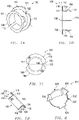
- a bearing 100 in accordance with one or more of the embodiments described herein includes a generally cylindrical sidewall 102 defining a first axial end 104 and a second axial end 106.
- An aperture 108 extends at least partially, such as entirely, between the first and second axial ends 104 and 106.
- the bearing 100 includes a gap 110 extending between the first and second axial ends 104 and 106.
- the gap 110 can be open such that circumferential ends of the bearing 100 are spaced apart from one another.
- the gap 110 can be closed such as, for example, by an adhesive, a weld, a mechanical fastener or deformation, or any other suitable method recognized by skilled artisans.
- a flange 112 extends radially from the generally cylindrical sidewall 102. In an embodiment, the flange 112 extends radially inward. In another embodiment, the flange 112 extends radially outward. In yet a further embodiment, the flange 112 can extend both radially inward and radially outward. In an embodiment, the flange 112 is disposed at a location proximate the first axial end 104 of the bearing 100. In a more particular embodiment, the flange 112 is disposed at the first axial end 104 such that no portion of the bearing 100 extends beyond the flange 112. In an embodiment, the flange 112 has a surface 116 and a surface 118 opposite the surface 116. The surface 116 can be disposed closer to the first axial end 104 of the bearing 100 than the surface 118.
- a feature 114 extends radially from the generally cylindrical sidewall 102 at a location between the flange 112 and the second axial end 106 of the bearing 100.
- the feature 114 can be a projection, a tine, an elongated wave structure, a dimple, a ridge, a corrugation, or another suitable element extending from the generally cylindrical sidewall 102.
- the feature 114 can be formed by stamping, pressing, milling, machining, grinding, ablating, deposition, lamination, adhesion, another operating procedure, or any combination thereof.
- the feature 114 is unitary with the generally cylindrical sidewall 102. In another embodiment, the feature 114 is not unitary with the generally cylindrical sidewall 102.
- the feature 114 can be fixedly coupled to the generally cylindrical sidewall 102.
- an artifact (not illustrated) can occur where the feature 114 is located along the generally cylindrical sidewall 102.
- features 114 that are pressed radially outward into the generally cylindrical sidewall 102 may form a corresponding recess along the radially inner side of the generally cylindrical sidewall 102.
- the feature 114 can have an arcuate profile, as viewed in cross section.
- the feature 114 can have a polygonal profile, as viewed in cross section.
- the feature 114 can have a square profile, as viewed in cross section.
- the feature 114 can include arcuate segments and polygonal segments, as viewed in cross section.
- the feature 114 can extend from the generally cylindrical sidewall 102 in a direction generally perpendicular thereto.
- the feature 114 can have a side surface which is perpendicular, or generally perpendicular, to the generally cylindrical sidewall 102 at the location from which the feature 114 extends from.
- the feature 114 can have a side surface canted relative to the generally cylindrical sidewall 102.
- the feature sidewall can be disposed at an angle, as measured with respect to the generally cylindrical sidewall 102, greater than 90°, greater than 100°, greater than 110°, greater than 120°, greater than 130°, greater than 140°, or greater than 150°.
- the feature 114 includes a plurality of features.
- the plurality of features 114 can include at least 2 features 114, at least 5 features 114, at least 10 features 114, at least 25 features 114, or at least 50 features 114.
- the plurality of features 114 includes no greater than 100 features.
- the plurality of features 114 can be spaced apart from one another. In an embodiment, the plurality of features 114 are equally spaced apart from one another as measured around a circumference of the generally cylindrical sidewall 102.
- the feature or features 114 extends in a same radial direction as the flange 112.
- the flange 112 and feature 114 can both extend radially inward or can both extend radially outward.
- the feature 114 extends in a different radial direction as compared to the flange 112.
- the flange 112 can extend radially inward and the feature can extend radially outward.
- the flange 112 and feature 114 both extend radially outward.
- the feature 114 may be particularly suitable for securing the bearing 100 to a structure.
- the flange 112 is spaced apart from the feature 114 by a distance, D, less than an axial height, H B , of the generally cylindrical sidewall 102.
- the distance, D is measured from the surface 118 of the flange 112 to a nearest point of the feature 114.
- D is less than H B , such as no greater than 0.99 H B , no greater than 0.95 H B , no greater than 0.9 H B , no greater than 0.85 H B , no greater than 0.8 H B , no greater than 0.75 H B , or no greater than 0.5 H B .
- D is no less than 0.01 H B , no less than 0.05 H B , or no less than 0.1 H B .
- the flange 112 can extend a maximum radial dimension, R F , as measured from an outermost surface of the generally cylindrical sidewall 102 to an outermost location of the flange 112.
- the feature 114 can extend a distance, D F , as measured from an outermost surface of the generally cylindrical sidewall 102.
- R F is different than D F .
- R F is greater than D F , such as wherein R F is at least 1.01 D F , at least 1.05 D F , at least 1.1 D F , at least 1.2 D F , at least 1.3 D F , at least 1.4 D F , at least 1.5 D F , or at least 1.75 D F .
- R F is less than D F , such as wherein R F is no greater than 0.99 D F , no greater than 0.95 D F , no greater than 0.9 D F , no greater than 0.75 D F , no greater than 0.5 D F , or no greater than 0.25 D F .
- R F is uniform as measured around the circumference of the flange 112.
- the flange 112 can have a non uniform radial dimension.
- an engagement feature 120 is formed in the flange 112.
- the engagement feature 120 can include a cutout 122 extending from the outermost surface of the flange 112 toward a central axis of the generally cylindrical sidewall 102.
- cutout 122 can extend at least 0.01 R F , at least 0.1 R F , at least 0.5 R F , or at least 0.9 R F as measured in a direction parallel with RF.
- the cutout 122 has a polygonal shape, when viewed parallel with the central axis of the generally cylindrical sidewall 102. In another embodiment, the cutout 122 has an arcuate shape when viewed parallel with the central axis of the generally cylindrical sidewall 102. In yet a further embodiment, the cutout 122 has a combination of polygonal portions and arcuate portions.
- the flange 112 has a thickness, T F , or average thickness in the case of a flange with varying thickness, which is no greater than the thickness of the cutout 122.
- the cutout extends at least 0.01 T F , at least 0.1 T F , at least 0.25 T F , at least 0.5 T F , at least 0.75 T F , or at least 0.9 T F .
- the cutout 122 extends through the entire thickness, T F , of the flange 112.
- the cutout 122 can have a first circumferential dimension, as measured from a top view at a radially innermost portion of the cutout 122, and a second circumferential dimension, as measured from a top view at a radially outermost portion of the cutout 122.
- the first circumferential dimension is different than the second circumferential dimension.
- the second circumferential dimension is greater than the first circumferential dimension.
- the second circumferential dimension can be at least 1.01 times greater than the first circumferential dimension, at least 1.1 times greater than the first circumferential dimension, at least 1.2 times greater than the first circumferential dimension, at least 1.3 times greater than the first circumferential direction, at least 1.4 times greater than the first circumferential dimension, at least 1.5 times greater than the first circumferential direction, or at least 2 times greater than the first circumferential dimension.
- the second circumferential dimension is no greater than 1000 times greater than the first circumferential dimension, no greater than 100 times greater than the first circumferential dimension, or no greater than 10 times greater than the first circumferential dimension.
- the engagement feature 120 comprises a projecting element, a corrugation, a ridge, a dimple, or a tine projecting from the flange (112).
- the engagement feature can also be another element projecting from the flange 112, or any combination thereof.
- the engagement feature 120 includes a plurality of features, such as at least two engagement features, at least three engagement features, at least four engagement features, at least five engagement features, at least ten engagement features, or at least fifty engagement features.
- the plurality of engagement features 120 includes no greater than 1000 engagement features, no greater than 500 engagement features, or no greater than 100 engagement features.
- at least two of the plurality of engagement features 120 have a generally same size, a generally same shape, or a generally same size and a generally same shape, as compared to one another.
- the plurality of engagement features can be spaced apart around the circumference of the flange 112.
- the engagement features 120 are equally spaced apart from one another around a circumference of the flange 120.
- at least one of the engagement features 120 can be circumferentially aligned with the gap 110.
- the generally cylindrical sidewall (102) comprises a low friction material (126).
- the generally cylindrical sidewall 102 can include a substrate 124 and a low friction material 126 coupled to the substrate 124.
- the substrate 124 can be coupled to the low friction material 126 by an adhesive, a primer layer, mechanical deformation, lamination, or any other suitable method.
- the substrate 124 can include a resilient material.
- the low friction material 126 is disposed along an inner surface of the generally cylindrical sidewall 102.
- the low friction material 126 can extend onto at least a portion, such as all, of the surface 116 of the flange 112.
- the low friction material 126 can be disposed along an outer surface of the generally cylindrical sidewall 102.
- the low friction material 126 can extend onto at least a portion, such as all, of the surface 118 of the flange 118.
- the substrate 124 can include a metal or an alloy such as steel.
- the low friction material 126 can include a material having a relatively low coefficient of friction.
- Exemplary materials include polymers, such as for example, a polyketone, a polyaramid, a polyimide, a polyetherimide, a polyamideimide, a polyphenylene sulfide, a polyphenylene sulfone, a fluoropolymer, a polybenzimidazole, a derivation thereof, or even a combination thereof.
- the low friction material 126 can at least partially include, or consist essentially of a polymer, such as a polyketone, a thermoplastic polyimide, a polyetherimide, a polyphenylene sulfide, a polyether sulfone, a polysulfone, a polyamideimide, a derivative thereof, or even a combination thereof.
- the low friction material 126 can include a polyketone, such as polyether ether ketone (PEEK), polyether ketone, polyether ketone ketone, polyether ketone ether ketone, a derivative thereof, or even a combination thereof.
- PEEK polyether ether ketone
- Fluoropolymers are used according to a particular embodiment.
- exemplary fluoropolymers include fluorinated ethylene propylene (FEP), polytetrafluoroethylene (PTFE), polyvinylidene fluoride (PVDF), perfluoroalkoxy (PFA), a terpolymer of tetrafluoroethylene, hexafluoropropylene, and vinylidene fluoride (THV), polychlorotrifluoroethylene (PCTFE), ethylene tetrafluoroethylene copolymer (ETFE), ethylene chlorotrifluoroethylene copolymer (ECTFE), or any combination thereof.
- FEP fluorinated ethylene propylene
- PTFE polytetrafluoroethylene
- PVDF polyvinylidene fluoride
- PFA perfluoroalkoxy
- THV vinylidene fluoride
- PCTFE polychlorotrifluoroethylene
- ETFE ethylene t
- the low friction material 126 can include one or more filler materials.
- Exemplary filler materials include glass fibers, carbon fibers, silicon, PEEK, aromatic polyester, carbon particles, bronze, fluoropolymers, thermoplastic fillers, aluminum oxide, polyamidimide (PAI), PPS, polyphenylene sulfone (PPSO2), LCP, aromatic polyesters, molybdenum disulfide, tungsten disulfide, graphite, grapheme, expanded graphite, boron nitrade, talc, calcium fluoride, or any combination thereof.
- the filler material can include alumina, silica, titanium dioxide, calcium fluoride, boron nitride, mica, Wollastonite, silicon carbide, silicon nitride, zirconia, carbon black, pigments, or any combination thereof.
- FIGs. 4 and 5 illustrate a structure 300 including an opening 302 defining a relief portion 304.
- the structure 300 can include a substrate, a tubular, a wall, or a sheet.
- the structure 300 can have a thickness, TS that is slightly less than the distance, D, between the feature 114 and the flange 112.
- TS is no less than 0.85 D, no less than 0.9 D, no less than 0.95 D, no less than 0.96 D, no less than 0.97 D, no less than 0.98 D, or no less than 0.99 D.
- TS is no greater than 1.5 D, no greater than 1.3 D, no greater than 1.1 D, no greater than 1.05 D, or no greater than 1.01 D.
- the structure 300 can have varying thickness.
- a thickness at first location along the circumference of the opening 302 can be greater than a thickness at a second location along the circumference of the opening 302.
- the bearing 100 can have multiple features 114 each having a different spatial arrangement with respect to the flange 112.
- the bearing 100 can include a plurality of features 114 at different distances, D, from the flange to permit engagement of the bearing 100 with structures of different thicknesses.
- the bearing 100 can include a first feature 114 spaced apart from the flange by a first distance and a second feature 114 spaced apart from the flange by a second distance.
- the first feature 114 can secure the bearing 100 to a structure 300 with a first thickness and the second feature 114 can secure the bearing 100 to a structure 300 with a second thickness.
- one sized bearing 100 can be used in a range of applications having different dimensional requirements.
- At least one feature 114 may secure the bearing 100 to the structure 300 by providing a matching interface with a relief portion 304 of the structure 300.
- the at least one feature 114 may be a square notch that matches a relief portion 304 in the form of a cylindrical projection or opening.
- at least one engagement feature 120 may secure the bearing 100 to the structure 300 by providing a matching interface with a relief portion 304 of the structure 300.
- the at least one engagement feature 120 may be a dimple located on a surface 116, 118 of the flange 112 that matches a relief portion 304 in the form of a cylindrical projection or opening.
- turning the bearing 100 while sitting in a relief portion 304 may create axial pressure between the engagement feature 120 and the feature 114 such that the bearing 100 may be locked without a second flange 112 on the bearing 100 required.
- the relief portion 304 can be in open communication with the opening 302 and extend radially outward therefrom.
- the relief portion 304 can be adapted to receive the feature 114.
- at least one relief portion 304 can have an arcuate shape, from a plan view.
- at least one relief portion 304 can have an polygonal shape, from a plan view.
- the relief portion 304 includes a plurality of relief portions spaced apart around a circumference of the opening 302.
- the relief portions 304 can be spaced apart equally around the circumference of the flange 112.
- the plurality of relief portions 304 can include at least 2 relief portions, at least 3 relief portions, at least 4 relief portions, at least 5 relief portions, or at least 10 relief portions. In another embodiment, the plurality of relief portions 304 includes no greater than 100 relief portions, no greater than 50 relief portions, or no greater than 25 relief portions.
- the relief portion 304 can include a first relief portion 306 and a second relief portion 308.
- the first and second relief portions 306 and 308 are diametrically opposite one another.
- the opening 302 has a first diameter, D1, as measured between opposite ends of the opening 302 and a second diameter, D2 measured by a distance between two radially outermost surfaces of the first and second relief portions 306 and 308.
- D2 is greater than D1.
- D 2 is at least 1.01 D 1 , at least 1.05 D 1 , at least 1.1 D 1 , or at least 1.2 D 1 .
- D2 is no greater than 3.0 D1, no greater than 2.5 D1, no greater than 2.0 D1, or no greater than 1.5 D1.
- the opening 302 can define a circumference, Co, and the relief portion can define a circumferential width, C RP , as measured along the circumference of the opening, that is less than C O .
- C RP is in a range of 0.1 C O to 0.99 C O , in a range of 0.2 C O to 0.9 C O , or in a range of 0.3 C O to 0.8 C O .
- FIG. 6 illustrates an alignment tool 400 including a body 402 and a complementary engagement feature 404 disposed on the body 402.
- the alignment tool 400 can engage with the engagement features 120 on the bearing 100 such that a user can rotate the bearing 100 through the alignment tool 400.
- the complementary engagement feature 404 has a shape similar to the engagement feature 120.
- the complementary engagement feature 404 can include a generally triangular projection adapted to be received in the triangular cutouts of the bearing 100.
- the body 402 can extend away from the complementary engagement feature 404, permitting a user to grasp the alignment tool 400 to rotate the bearing 100.
- the body 402 has a generally cylindrical sidewall 406 and opposite axial ends 408 and 410.
- the complementary engagement feature 404 can be disposed proximate to one of the opposite axial ends 408 or 410.
- a projection 412 can extend from the body 402 and fit within the aperture 108 of the bearing 100. In an embodiment, the projection 412 is disposed between the complementary engagement features 404.
- the projection 412 can have a diameter less than or generally equal to the diameter of the aperture 108. The projection 412 permits smoother engagement between the alignment tool 400 and the bearing 100 by allowing a user to more easily position and align the alignment tool 400 relative to the aperture 108 and engagement features 120.
- the alignment tool 400 can be powered. That is, the alignment tool 400 can include an urging element adapted to rotate the complementary engagement feature 404. In another embodiment, the alignment tool 400 can be adapted to be connected to a power tool. In a further embodiment, the alignment tool 400 is adapted to be manually operated.
- the alignment tool 400 can include an encoding element (not illustrated) adapted to determine the relative rotational position of the alignment tool 400 (e.g., the complementary engagement features 404).
- the encoding element or another sensor can sense a rotational position of the alignment tool before application of torque on the bearing 100 and after application of torque on the bearing 100.
- the bearing 100 can be positioned on the structure 300 at a location adjacent to the opening 302.
- the bearing 100 can then be at least partially inserted into the opening 302 such that the second axial end 106 extends at least partially into the opening 302.
- the bearing 100 can be inserted into the opening 302 until the surface 118 of the bearing 100 contacts a surface of the structure 300.
- the alignment tool 400 can then be aligned with the bearing 100 such that the complementary engagement feature 404 of the alignment tool 400 is aligned with the engagement feature 120 of the bearing.
- the alignment tool 400 can then be used to rotate the bearing 100 within the opening 302 until the feature 114 is not disposed in axial alignment with the relief portion 304.
- the bearing 100 is adapted to be installed in the opening 302 in a first rotational orientation.
- the feature 114 of the bearing 100 is aligned with the relief portion 304.
- the bearing can be rotated to a second rotational orientation different from the first rotational orientation.
- the second rotational orientation of the bearing 100 puts the feature 114 at a location spaced apart from the relief portion 304 such that the bearing 100 cannot be pulled axially from the opening 302 without at least partially rotating the bearing 100.
- the first rotational orientation is different from the second rotational orientation by at least 1°, at least 5°, at least 10°, at least 20°, at least 30°, at least 40°, at least 50°, at least 60°, at least 70°, at least 80°, or at least 90°.
- the first rotational orientation is different from the second rotational orientation by less than 360°, less than 270°, less than 180°, or less than 91°.
- the rotational difference between the first rotational orientation and second rotational orientation is largely determined by the arrangement of relief portions 304. A greater number of relief portions 304 may result in a lesser difference in rotational orientation between the first and second rotational orientations.
Landscapes
- Engineering & Computer Science (AREA)
- General Engineering & Computer Science (AREA)
- Mechanical Engineering (AREA)
- Sliding-Contact Bearings (AREA)
- Rolling Contact Bearings (AREA)
- Mounting Of Bearings Or Others (AREA)
- Glass Compositions (AREA)
Claims (14)
- Palier (100) comprenant :une paroi latérale généralement cylindrique (102) définissant des première et seconde extrémités axiales (104, 106) et une ouverture (108) s'étendant entre les première et seconde extrémités axiales (104, 106) et un espace (110) s'étendant entre la première et la seconde extrémité axiale (104, 106) ;un flasque (112) s'étendant radialement à partir de la paroi latérale généralement cylindrique (102) à un emplacement proche de la première extrémité axiale (104) ; etun détail (114) s'étendant radialement à partir de la paroi latérale généralement cylindrique (102) à un emplacement disposé entre le flasque (112) et la seconde extrémité axiale (106),dans lequel la paroi latérale généralement cylindrique (102) comprend un matériau à faible frottement (126) etdans lequel le flasque (112) comprend un élément de mise en prise (120) décalé circonférentiellement de l'espace (110),dans lequel l'élément de mise en prise (120) comprend un élément en saillie, une ondulation, une nervure, un creux ou une dent faisant saillie depuis le flasque (112).
- Ensemble comprenant :une structure (300) ayant une ouverture (302) avec une partie en relief (304) ; etun palier (100) selon la revendication 1.
- Procédé d'installation d'un palier (100), comprenant :la fourniture d'un palier (100) selon la revendication 1 ;l'alignement du palier (100) avec une surface ayant une ouverture (302) avec une partie en relief (304) à un emplacement circonférentiel correspondant au détail (114) ;l'insertion du palier (100) dans l'ouverture de sorte que le détail (114) passe à travers la partie en relief (304) ;la pression du palier (100) dans l'ouverture jusqu'à ce que le flasque (112) entre en contact avec la surface ; etla rotation du palier (100) jusqu'à ce que le détail (114) soit décalé angulairement de la partie en relief (304).
- Palier (100), ensemble ou procédé selon l'une quelconque des revendications 1 à 3, dans lequel la paroi latérale généralement cylindrique (102) comprend un substrat (124) et un matériau à faible frottement (126) et dans lequel le matériau à faible frottement (126) est couplé au substrat (124).
- Palier (100), ensemble ou procédé selon la revendication 4, dans lequel le détail (114) s'étend radialement vers l'extérieur à partir de la paroi latérale généralement cylindrique (102) et dans lequel le matériau à faible frottement (126) est disposé le long d'une surface interne de la paroi latérale généralement cylindrique (102).
- Palier (100), ensemble ou procédé selon l'une quelconque des revendications 1 à 3, dans lequel le flasque (112) est disposé à la première extrémité axiale (104) du palier (100).
- Palier (100), ensemble ou procédé selon l'une quelconque des revendications 1 à 3, dans lequel le flasque (112) est espacé du détail (114) d'une distance, D, dans lequel la paroi latérale généralement cylindrique (102) a un axe axial hauteur, HB et dans lequel D est inférieure à HB, tel que dans lequel D n'est pas supérieure à 0,99 HB, pas supérieure à 0,95 HB, pas supérieure à 0,9 HB, pas supérieure à 0,85 HB, pas supérieure à 0,8 HB, pas supérieure à 0,75 HB ou pas supérieure à 0,5 HB et dans lequel D n'est pas inférieure à 0,01 HB, pas inférieure à 0,05 HB ou pas inférieure à 0,1 HB.
- Palier (100), ensemble ou procédé selon l'une quelconque des revendications 1 à 3, dans lequel le flasque (112) et le détail (114) s'étendent dans une même direction radiale l'un par rapport à l'autre, tel que dans lequel le flasque (112) et le détail (114) s'étendent tous deux radialement vers l'extérieur à partir de la paroi latérale généralement cylindrique (102).
- Palier (100), ensemble ou procédé selon l'une quelconque des revendications 1 à 3, dans lequel le flasque (112) a une première surface et une seconde surface opposée à la première surface, dans lequel la première surface est plus proche de la première extrémité axiale (104 ) que la seconde surface et dans lequel la première surface comprend un matériau à faible frottement (126).
- Palier (100), ensemble ou procédé selon l'une quelconque des revendications 1 à 3, dans lequel le flasque (112) s'étend sur une dimension radiale maximale, RF, telle que mesurée à partir d'une surface la plus à l'extérieur de la paroi latérale généralement cylindrique (102), dans lequel le détail (114) s'étend sur une distance, DF, telle que mesurée à partir d'une surface la plus à l'extérieur de la paroi latérale généralement cylindrique (102) et dans lequel RF et DF sont différentes l'une de l'autre.
- Palier (100), ensemble ou procédé selon la revendication 10, dans lequel RF est supérieure à DF, tel que dans lequel RF vaut au moins 1,01 DF, au moins 1,05 DF, au moins 1,1 DF, au moins 1,2 DF, au moins 1,3 DF, au moins 1,4 DF, au moins 1,5 DF ou au moins 1,75 DF.
- Palier (100), ensemble ou procédé selon la revendication 10, dans lequel RF est inférieure à DF, tel que dans lequel RF n'est pas supérieure à 0,99 DF, pas supérieure à 0,95 DF, pas supérieure à 0,9 DF, pas supérieure à 0,75 DF, pas supérieure à 0,5 DF ou pas supérieure à 0,25 DF.
- Palier (100), ensemble ou procédé selon l'une quelconque des revendications 10 à 12, dans lequel RF est uniforme autour de la circonférence du flasque (112).
- Palier (100), ensemble ou procédé selon l'une quelconque des revendications 1 à 3, dans lequel l'élément de mise en prise (120) comprend une découpe (122) s'étendant à partir d'une surface la plus extérieure du flasque (112) vers un axe central de la paroi latérale généralement cylindrique (102).
Applications Claiming Priority (2)
| Application Number | Priority Date | Filing Date | Title |
|---|---|---|---|
| US201662370021P | 2016-08-02 | 2016-08-02 | |
| PCT/US2017/044800 WO2018026756A1 (fr) | 2016-08-02 | 2017-08-01 | Palier |
Publications (3)
| Publication Number | Publication Date |
|---|---|
| EP3494316A1 EP3494316A1 (fr) | 2019-06-12 |
| EP3494316A4 EP3494316A4 (fr) | 2020-07-01 |
| EP3494316B1 true EP3494316B1 (fr) | 2022-06-01 |
Family
ID=61069036
Family Applications (1)
| Application Number | Title | Priority Date | Filing Date |
|---|---|---|---|
| EP17837500.2A Active EP3494316B1 (fr) | 2016-08-02 | 2017-08-01 | Palier |
Country Status (10)
| Country | Link |
|---|---|
| US (1) | US10309456B2 (fr) |
| EP (1) | EP3494316B1 (fr) |
| JP (1) | JP6802898B2 (fr) |
| KR (4) | KR102468433B1 (fr) |
| CN (1) | CN109477519B (fr) |
| CA (1) | CA3032659C (fr) |
| ES (1) | ES2924258T3 (fr) |
| MX (1) | MX2019000876A (fr) |
| PL (1) | PL3494316T3 (fr) |
| WO (1) | WO2018026756A1 (fr) |
Families Citing this family (11)
| Publication number | Priority date | Publication date | Assignee | Title |
|---|---|---|---|---|
| USD864691S1 (en) * | 2016-06-14 | 2019-10-29 | Christian Campos | Front and rear engine cover alignment tool and seal installer |
| PL3494316T3 (pl) | 2016-08-02 | 2022-09-19 | Saint-Gobain Performance Plastics Corporation | Łożysko |
| JP2022514916A (ja) * | 2018-12-22 | 2022-02-16 | サン-ゴバン パフォーマンス プラスティックス コーポレイション | トラッカー・アセンブリのための軸受アセンブリ、並びに当該軸受アセンブリの製作及び使用方法 |
| TWI764109B (zh) * | 2019-03-22 | 2022-05-11 | 美商聖高拜塑膠製品公司 | 複合軸承及其製造與使用方法 |
| DE102019209027A1 (de) * | 2019-06-21 | 2020-12-24 | Siemens Aktiengesellschaft | Lageranordnung |
| EP4055291A4 (fr) * | 2019-11-08 | 2023-11-22 | Saint-Gobain Performance Plastics Corporation | Palier fendu, assemblage, et procédé de fabrication et d'utilisation dudit palier |
| JP2023504771A (ja) * | 2019-12-06 | 2023-02-07 | サン-ゴバン パフォーマンス プラスティックス コーポレイション | フランジ付き軸受、組立体、並びにその製造及び使用方法 |
| DE102020208107A1 (de) | 2020-06-30 | 2021-12-30 | Robert Bosch Gesellschaft mit beschränkter Haftung | Drehlagervorrichtung und Materialuntersuchungsgerät mit Drehlagervorrichtung |
| JP7521420B2 (ja) * | 2020-12-24 | 2024-07-24 | 株式会社デンソー | ダンパー、電子制御装置、および組付方法 |
| CN116964928A (zh) | 2021-04-16 | 2023-10-27 | 美国圣戈班性能塑料公司 | 用于跟踪器组件的轴承组件及其制造和使用方法 |
| KR20240124302A (ko) | 2021-12-21 | 2024-08-16 | 생-고뱅 퍼포먼스 플라스틱스 코포레이션 | 리브를 갖는 전기 전도성 베어링, 및 이를 제조 및 사용하는 방법 |
Citations (3)
| Publication number | Priority date | Publication date | Assignee | Title |
|---|---|---|---|---|
| US20120240350A1 (en) * | 2011-03-22 | 2012-09-27 | Saint-Gobain Performance Plastics Pampus Gmbh | Bushing with transfigurable electrical conduction state |
| US20140246266A1 (en) * | 2011-10-18 | 2014-09-04 | Nsk Ltd. | Steering column support apparatus |
| CN204458837U (zh) * | 2014-10-28 | 2015-07-08 | 安徽汉升新金属技术有限公司 | 一种衬套 |
Family Cites Families (231)
| Publication number | Priority date | Publication date | Assignee | Title |
|---|---|---|---|---|
| US1325849A (en) | 1919-12-23 | hoover | ||
| US590322A (en) | 1897-09-21 | Spindle-bearing | ||
| US389819A (en) | 1888-09-18 | Roller-bearing for axles and shafts | ||
| US616094A (en) | 1898-12-20 | The norp | ||
| US2761202A (en) * | 1956-09-04 | R beare | ||
| US231866A (en) | 1880-08-31 | taylor | ||
| US503609A (en) | 1893-08-22 | Peder lobben | ||
| US413525A (en) | 1889-10-22 | Anti-friction bearing for vehicle-wheels | ||
| US259948A (en) | 1882-06-20 | Tille | ||
| US548651A (en) | 1895-10-29 | Spindle-bearing for spinning-machines | ||
| US447531A (en) | 1891-03-03 | andrews | ||
| US664946A (en) | 1900-03-21 | 1901-01-01 | Adolph Haenichen | Shaft-bearing. |
| US917522A (en) | 1907-10-03 | 1909-04-06 | Alstyne Loucks Van | Car-bearing. |
| US1151847A (en) | 1909-08-27 | 1915-08-31 | Werner Ahrens | Antifriction-bearing. |
| US1091830A (en) | 1910-02-14 | 1914-03-31 | Isaac A George | Bearing. |
| US1182188A (en) | 1911-07-17 | 1916-05-09 | James J Mcgowan | Bearing for pin-cylinders. |
| US1029075A (en) | 1911-08-10 | 1912-06-11 | Hyatt Roller Bearing Co | Collared spirally-wound roll. |
| US1197006A (en) | 1916-04-26 | 1916-09-05 | New Britain Machine Co | Buffing-machine. |
| US1346121A (en) | 1916-05-09 | 1920-07-13 | Andrew Albright Jr | Bearing |
| US1327301A (en) | 1918-10-09 | 1920-01-06 | James B Watson | Bearing |
| US1648441A (en) | 1920-08-18 | 1927-11-08 | Elbert O Brower | Machine element |
| US1526632A (en) | 1922-08-21 | 1925-02-17 | Fischbach Paul | Shackle |
| US1615499A (en) | 1926-05-11 | 1927-01-25 | Charlie J Angell | One-way disk plow |
| US1759149A (en) | 1926-09-27 | 1930-05-20 | Delta Star Electric Co | Rotary insulator |
| US1790253A (en) | 1927-02-09 | 1931-01-27 | Harold J Clark | Crank-shaft and bearing assembly |
| US1904203A (en) | 1928-04-11 | 1933-04-18 | Celanese Corp | Bearing and application thereof |
| US1910300A (en) * | 1928-05-07 | 1933-05-23 | Gemmer Mfg Co | Bushing for motor car steering columns |
| US1738037A (en) * | 1928-05-21 | 1929-12-03 | Warner Corp | Spring bushing |
| US1882102A (en) | 1929-04-27 | 1932-10-11 | Nomy Ab | Shaft bearing |
| US1998888A (en) | 1930-03-05 | 1935-04-23 | Nomy Ab | Bearing |
| US2016757A (en) | 1931-05-14 | 1935-10-08 | Trayer Bolt Company Inc | Wear compensating bearing |
| US2043790A (en) | 1932-01-08 | 1936-06-09 | Wagner Electric Corp | Thrust washer assembly |
| US2019564A (en) | 1932-05-27 | 1935-11-05 | Apex Electrical Mfg Co | Laundry machine mechanism |
| US2074203A (en) | 1932-11-28 | 1937-03-16 | Benedek Elek | Pump |
| US1947066A (en) | 1932-12-14 | 1934-02-13 | Samuel M Langston Co | Corrugator |
| US2103895A (en) | 1933-03-13 | 1937-12-28 | Herbert S Simpson | Muller |
| US2006404A (en) | 1934-01-10 | 1935-07-02 | Western Electric Co | Material handling apparatus |
| US2145864A (en) | 1934-07-12 | 1939-02-07 | Ohio Crankshaft Co | Method of making hardened surface articles |
| US2088937A (en) | 1934-09-21 | 1937-08-03 | Walworth Patents Inc | Valve |
| US2174261A (en) | 1935-03-20 | 1939-09-26 | Packard Motor Car Co | Gear mounting |
| US2113167A (en) | 1935-09-09 | 1938-04-05 | B B B Corp | Water pump seal |
| US2124132A (en) * | 1936-03-24 | 1938-07-19 | Glacier Co Ltd | Manufacture of bearings |
| US2182012A (en) | 1937-01-07 | 1939-12-05 | Baird Machine Co | Spindle |
| US2182247A (en) | 1937-01-19 | 1939-12-05 | Globe Oil Tools Co | Well bit construction |
| US2126039A (en) | 1937-03-08 | 1938-08-09 | Chicago Pneumatic Tool Co | Earth boring drill |
| US2266140A (en) | 1939-04-15 | 1941-12-16 | Singer Mfg Co | Chain-stitch sewing machine |
| US2259447A (en) | 1939-06-05 | 1941-10-21 | Symington Gould Corp | Journal box assembly |
| US2283939A (en) | 1939-10-19 | 1942-05-26 | Rudolph W Miller | Journal lubricator |
| US2306048A (en) | 1939-11-17 | 1942-12-22 | Fast Bearing Company | Combined radial and thrust bearing unit |
| US2226524A (en) | 1939-11-21 | 1940-12-24 | S K F Ind Inc | Means for securing a bearing to a shaft |
| US2350272A (en) | 1940-06-22 | 1944-05-30 | Gen Motors Corp | Spindle |
| US2440890A (en) | 1941-01-03 | 1948-05-04 | Turbo Engineering Corp | Turbine bearing |
| US2331652A (en) | 1941-04-30 | 1943-10-12 | Timken Axle Co Detroit | Brake mechanism |
| US2309397A (en) | 1941-05-21 | 1943-01-26 | Illmer Louis | Protective journal bearing means |
| US2358510A (en) * | 1942-01-09 | 1944-09-19 | Holland Co | Spring snubber unit |
| US2369684A (en) | 1942-01-13 | 1945-02-20 | Bliss E W Co | Rolling mill construction |
| US2404429A (en) | 1943-01-02 | 1946-07-23 | Gen Motors Corp | Railway journal box |
| US2424757A (en) | 1945-06-06 | 1947-07-29 | Jr Ferdinand Klumpp | Self-locking bushing |
| US2474489A (en) | 1946-02-07 | 1949-06-28 | Beloit Iron Works | Rocker mounting for rotary bearings |
| US2608448A (en) | 1946-03-29 | 1952-08-26 | Toledo Scale Co | Knife edge pivot construction |
| US2631905A (en) | 1946-08-06 | 1953-03-17 | Nat Lead Co | Bearing surface |
| US2436274A (en) | 1946-09-14 | 1948-02-17 | Colin S Watt | Bearing |
| US2530520A (en) | 1946-09-17 | 1950-11-21 | Everel Propeller Corp | Propeller hub |
| US2575830A (en) | 1947-03-20 | 1951-11-20 | Morgan Construction Co | Thrust bearing |
| US2652296A (en) | 1948-09-03 | 1953-09-15 | Skf Ind Inc | Multirow cylindrical roller bearing |
| US2693965A (en) | 1948-10-28 | 1954-11-09 | James W Briney | Adjustable coupling |
| US2557813A (en) | 1948-12-07 | 1951-06-19 | Edward F Burton | Method and apparatus for preparing frozen confections |
| US2638388A (en) | 1949-04-11 | 1953-05-12 | Baker Perkins Ltd | Adjustment means for the rolls of multiroll chocolate and like refining machines |
| US2614897A (en) | 1950-03-11 | 1952-10-21 | West Bend Aluminum Co | Main bearing for multicrank engines |
| US2668316A (en) * | 1950-08-29 | 1954-02-09 | Chrysler Corp | Bushing |
| US2665176A (en) | 1951-10-26 | 1954-01-05 | Int Harvester Co | Bearing |
| US2685483A (en) | 1952-09-03 | 1954-08-03 | Joseph E Morra | Shaft bearing |
| US2719064A (en) | 1952-12-11 | 1955-09-27 | John R Barnard | Conical self-adjusting bearing |
| US2765657A (en) | 1953-01-28 | 1956-10-09 | Karl L Schaus | Drive shaft journaling mechanism for gas meters |
| US3058786A (en) | 1956-02-03 | 1962-10-16 | Aerojet General Co | Composite bearing |
| US2861850A (en) | 1956-03-16 | 1958-11-25 | Abell Howe Company | Wheel and axle assembly |
| LU35574A1 (fr) | 1956-09-12 | |||
| US3159045A (en) | 1957-04-19 | 1964-12-01 | Gen Motors Corp | Drive mechanism |
| US2991134A (en) | 1957-07-17 | 1961-07-04 | Miller Lubricator Company | Journal box packing |
| US2897022A (en) | 1957-09-05 | 1959-07-28 | Torrington Co | Mounting for roller bearings |
| US3035878A (en) | 1959-02-09 | 1962-05-22 | Havilland Engine Co Ltd | Flexible supporting arrangement for rotating members |
| US2980472A (en) | 1959-04-10 | 1961-04-18 | Miller Gladys Davis | Lubricator for traction motor suspension bearings |
| US3095770A (en) | 1959-10-26 | 1963-07-02 | Jack N Binns | Contour roll-turning lathe |
| US3001007A (en) * | 1959-11-13 | 1961-09-19 | Heyman Mfg Company | Self-locking bushing |
| US3005324A (en) | 1960-01-11 | 1961-10-24 | Zeller Corp | Universal joint |
| US3061385A (en) | 1960-02-23 | 1962-10-30 | Timken Roller Bearing Co | Railway journal box stop means |
| US3053580A (en) | 1960-03-16 | 1962-09-11 | Bullard Co | Slide bearing |
| US3116957A (en) | 1961-08-08 | 1964-01-07 | Tyman H Fikse | Self-oiling elastic journal bearing |
| US3101222A (en) | 1962-02-02 | 1963-08-20 | Gen Motors Corp | Bearing assembly |
| US3156507A (en) | 1962-07-30 | 1964-11-10 | American Brake Shoe Co | Journal lubricators |
| US3283189A (en) | 1963-08-13 | 1966-11-01 | Bendix Corp | Timer and distributor for ignition systems and the like |
| US3351394A (en) | 1965-01-07 | 1967-11-07 | Mechanical Tech Inc | Hydrostatic bearings for a rotatable element |
| US3372960A (en) | 1965-10-21 | 1968-03-12 | Illinois Tool Works | Self-locking bushing |
| US3369852A (en) | 1965-12-06 | 1968-02-20 | Arthur F. Emmerson | Journal lubricator |
| US3350148A (en) | 1966-02-11 | 1967-10-31 | Gen Bearing Co | Ball bearing seal assembly |
| US3411335A (en) | 1966-02-16 | 1968-11-19 | Wilson Eng Co Inc Lee | Thrust bearing assembly |
| US3438686A (en) * | 1967-01-23 | 1969-04-15 | Murray Co Inc | Bearing support bushing |
| US3413046A (en) | 1967-03-14 | 1968-11-26 | Int Research & Dev Co Ltd | Balancing support stand |
| US3441288A (en) | 1967-04-27 | 1969-04-29 | Rockwell Standard Co | Steering knuckle sealing means |
| US3510178A (en) | 1968-06-06 | 1970-05-05 | Rex Chainbelt Inc | Spherical bearing with integral rotation limiting means |
| US3618443A (en) * | 1969-07-15 | 1971-11-09 | Donald F Fitzner | Snap-in gasket holder |
| US3574492A (en) | 1969-09-26 | 1971-04-13 | Gen Signal Corp | Bushing arrangement for rotary shafts |
| US3677613A (en) | 1971-05-21 | 1972-07-18 | Int Harvester Co | Self aligning and self adjusting thrust bushing assembly |
| US3804479A (en) | 1972-12-21 | 1974-04-16 | Rexnord Inc | Low friction fabric-lined bearings and improved fabric therefor |
| US3881791A (en) | 1973-03-02 | 1975-05-06 | Skf Ind Trading & Dev | Dry journal bearing |
| US3874752A (en) * | 1974-01-18 | 1975-04-01 | Yasutaka Imazaike | Synthetic resin-made bearing |
| US3893734A (en) | 1974-04-01 | 1975-07-08 | Ford Motor Co | Thrust bearing |
| US4048703A (en) * | 1975-02-14 | 1977-09-20 | Glyco-Metall-Werke Daelen & Loos Gmbh | Collar sleeves and process and tool for the manufacture thereof |
| NL179154C (nl) | 1975-02-17 | 1986-07-16 | Skf Ind Trading & Dev | Rotary boorkop. |
| US4211453A (en) | 1976-04-12 | 1980-07-08 | Skf Industrial Trading And Development Co. B.V. | Rock drill bit lubrication system |
| US4056293A (en) | 1976-04-20 | 1977-11-01 | The Torrington Company | Segmented retainers |
| US4090749A (en) | 1976-12-06 | 1978-05-23 | Emerson Electric Co. | Twist lock self-aligning bearing system |
| US4136748A (en) | 1977-11-07 | 1979-01-30 | The Timken Company | Roller-type rock bit and bearing arrangement therefor |
| GB2047327B (en) * | 1978-11-27 | 1982-10-06 | Scharwaechter Gmbh Co Kg | Leaf hinge having maintenance free hinge-eye bushes |
| US4277113A (en) | 1979-10-01 | 1981-07-07 | Mechanical Technology Incorporated | Composite material compliant bearing element |
| US4341426A (en) | 1980-10-22 | 1982-07-27 | The Timken Company | Clamp-up device for roll neck bearings |
| US4403814A (en) | 1982-01-25 | 1983-09-13 | Mcgill Manufacturing Company, Inc. | Method for locking an anti-friction bearing to a shaft and apparatus for accomplishing the same |
| US4514098A (en) | 1982-09-01 | 1985-04-30 | Dresser Industries, Inc. | Wound wire bearing |
| US4535196A (en) * | 1982-11-04 | 1985-08-13 | Milne John D | Electrical anti-short bushing |
| US4487379A (en) * | 1982-12-07 | 1984-12-11 | The Stanley Works | Coilable tape rule with shifting hub, reel assembly therefor, and method of assembling |
| US4598603A (en) | 1983-08-29 | 1986-07-08 | Toyoda Gosei Co., Ltd. | Steering wheel |
| DE3346843A1 (de) | 1983-12-23 | 1985-07-11 | Schubert & Salzer Maschinenfabrik Ag, 8070 Ingolstadt | Offenend-rotorspinnvorrichtung |
| GB8511529D0 (en) | 1985-05-07 | 1985-06-12 | Data Recording Instr Co | Bush elements |
| GB8526834D0 (en) | 1985-10-31 | 1985-12-04 | Black & Decker Inc | Electric motors & components |
| US4884899A (en) | 1987-04-03 | 1989-12-05 | Schwartzman Everett H | Resiliently mounted fluid bearing assembly |
| US4828403A (en) | 1987-04-03 | 1989-05-09 | Schwartzman Everett H | Resiliently mounted fluid bearing assembly |
| JP2616922B2 (ja) | 1987-05-22 | 1997-06-04 | 株式会社日立製作所 | スクリユー圧縮機 |
| US5564836A (en) | 1987-05-29 | 1996-10-15 | Kmc, Inc. | Multi-deflection pad hydrodynamic thrust bearings having a multimode construction |
| US5125754A (en) | 1987-05-29 | 1992-06-30 | Ide Russell D | Multi-deflection pad hydrodynamic thrust and journal bearings having a modular construction |
| US5393145A (en) | 1987-05-29 | 1995-02-28 | Ide; Russell D. | Pad type hydrodynamic thrust bearings having a modular construction |
| GB8805124D0 (en) | 1988-03-03 | 1988-03-30 | Blair George Plc | Improved self-adjusting bearing |
| US4965965A (en) | 1988-07-06 | 1990-10-30 | Wallin Sven E | Grinding head for surfacing and polishing stone, marbles and other hard materials |
| US5128574A (en) | 1989-04-11 | 1992-07-07 | Canon Kabushiki Kaisha | Brushless motor |
| US5056965A (en) | 1989-11-03 | 1991-10-15 | Cbc Industries, Inc. | Method of controlled inventory for bushings |
| DE3943273C2 (de) | 1989-12-29 | 1996-07-18 | Klaus Union Armaturen | Horizontal angeordnete Kreiselpumpe mit Spaltrohrmagnetkupplung |
| FR2669691A1 (fr) | 1990-11-28 | 1992-05-29 | Ecia Equip Composants Ind Auto | Palier lisse souple et son application aux directions d'automobile. |
| GB9127191D0 (en) | 1991-12-21 | 1992-02-19 | T & N Technology Ltd | Flanged bearings |
| FR2685675B1 (fr) | 1991-12-26 | 1994-04-01 | Aerospatiale Ste Nationale Indle | Dispositif de palier elastomerique cylindrique a grand debattement angulaire. |
| GB9204769D0 (en) | 1992-03-05 | 1992-04-15 | Black & Decker Inc | Workcentre and supports |
| US5190450A (en) | 1992-03-06 | 1993-03-02 | Eastman Kodak Company | Gear pump for high viscosity materials |
| DE4213831C2 (de) * | 1992-04-28 | 1996-06-20 | Glyco Metall Werke | Gerollte Lagerbuchse und Zapfen- oder Wellenverbindung mit einer solchen Lagerbuchse |
| US5332329A (en) | 1992-05-14 | 1994-07-26 | Hill Thomas R | Anti-twist bushing |
| US5269607A (en) | 1992-06-29 | 1993-12-14 | The Torrington Company | Bearing assembly with locking device |
| US5228787A (en) | 1992-06-29 | 1993-07-20 | The Torrington Company | Bearing assembly with locking device |
| US5471859A (en) | 1992-07-20 | 1995-12-05 | T. Sendzimir, Inc. | Cluster mill crown adjustment system |
| FR2697301B1 (fr) * | 1992-10-23 | 1995-01-13 | Socapex Amphenol | Dispositif de rivet à force d'insertion nulle. |
| JP2512887Y2 (ja) * | 1992-11-05 | 1996-10-02 | 株式会社電業社機械製作所 | ゴム軸受 |
| JP3339100B2 (ja) * | 1993-03-23 | 2002-10-28 | オイレス工業株式会社 | ゴム製外被付きブッシュ及びその製造方法 |
| US5501473A (en) | 1993-08-13 | 1996-03-26 | Power Tool Holders Incorporated | Chuck |
| CA2182732A1 (fr) | 1994-02-08 | 1995-08-17 | Noel Francis Sheedy | Palier lisse |
| US5511885A (en) | 1994-02-18 | 1996-04-30 | Xerox Corporation | Composite flanged bearing having anti-rotation feature |
| US5549394A (en) | 1994-11-10 | 1996-08-27 | Hycomp, Inc. | Bearing arrangement having a polyimide graphite-fiber reinforced composite embedded therein |
| USD373069S (en) * | 1994-12-19 | 1996-08-27 | Mccarthy John | Insert for mounting a decorative figure onto an antenna |
| DE19681309C2 (de) | 1995-03-27 | 2002-02-28 | Asmo Co Ltd | Wischervorrichtung |
| DE19531278C1 (de) * | 1995-08-25 | 1997-01-30 | Daimler Benz Ag | Gelenk zur Schwenklagerung eines Mantelrohrs einer neigungseinstellbaren Lenksäule an einer Mantelrohraufhängung eines Fahrzeugs |
| CA2233486C (fr) | 1995-10-02 | 2003-06-17 | Thomas W. Ramsay | Joint d'etancheite et/ou palier rotatif |
| JP3731246B2 (ja) * | 1996-03-28 | 2006-01-05 | オイレス工業株式会社 | 軸受の製造方法 |
| GB9623126D0 (en) | 1996-11-06 | 1997-01-08 | Timken Co | Bearing assembly |
| JPH10159836A (ja) * | 1996-11-29 | 1998-06-16 | Nec Corp | 軸受け構造 |
| DE19651176B4 (de) | 1996-12-10 | 2004-02-12 | Skf Gmbh | Lösbare axiale Sicherung |
| US5906029A (en) * | 1997-03-25 | 1999-05-25 | Fox; Larry | Hinge repair kit and installation method |
| DE19739929A1 (de) | 1997-09-11 | 1999-04-01 | Glyco Metall Werke | Extrem dünnwandiges Gleitlager |
| DE19753111A1 (de) | 1997-11-29 | 1999-06-10 | Federal Mogul Wiesbaden Gmbh | Lagerbuchse mit Mittelbund sowie deren Verwendung und Herstellungsverfahren |
| JPH11303857A (ja) * | 1998-04-14 | 1999-11-02 | Zexel:Kk | つば付巻ブッシュ用平板及びつば付巻ブッシュ |
| US6036370A (en) | 1998-08-31 | 2000-03-14 | General Motors Corporation | Wheel bearing with self-aligning wheel speed sensor ring |
| CN1433509A (zh) * | 2000-02-09 | 2003-07-30 | 西加特技术有限责任公司 | 具有高的箍强度以抵制变形的公差配合环 |
| US6637827B2 (en) | 2000-02-28 | 2003-10-28 | Myron Stuart Hurwitz | Generation of in-line skates and skate-boards wtih safety “edging friction control™” |
| US6447166B1 (en) | 2000-05-24 | 2002-09-10 | Illinois Tool Works Inc. | Linear bushing |
| US6804872B2 (en) * | 2000-07-05 | 2004-10-19 | Siemens Vdo Automotive Inc. | Method of forming a roll pin compression limiter |
| DE10032590A1 (de) | 2000-07-07 | 2002-01-17 | Skf Gmbh | Verriegelbare Lagereinheit |
| US6431755B1 (en) | 2000-08-11 | 2002-08-13 | Loren T. Schneider | Drive train for use with a kneader apparatus |
| DE10043048C2 (de) | 2000-09-01 | 2002-10-31 | Zf Boge Gmbh | Vordere Lageranordnung für ein kippbares Fahrerhaus eines Lastkraftwagens |
| US6559633B1 (en) | 2000-09-18 | 2003-05-06 | Freudenberg-Nok General Partnership | Speed sensor with a seal |
| US6467965B1 (en) * | 2000-09-29 | 2002-10-22 | Xerox Corporation | Bearing |
| US6936951B1 (en) | 2000-11-27 | 2005-08-30 | Grq Instruments, Inc. | Smart sonic bearings and method for frictional force reduction and switching |
| US6634616B2 (en) | 2000-12-01 | 2003-10-21 | General Electric Company | Twist lock fixture attachment system |
| DE10061382C1 (de) * | 2000-12-09 | 2002-09-05 | Ks Gleitlager Gmbh | Verfahren zur Herstellung einer Bundbuchse |
| US6498475B2 (en) | 2001-03-06 | 2002-12-24 | Delphi Technologies, Inc. | Performance sensor ring with reduced mass |
| DE10121769A1 (de) * | 2001-05-04 | 2002-12-05 | Bosch Gmbh Robert | Maschinengehäuse |
| JP2002340001A (ja) * | 2001-05-21 | 2002-11-27 | Fuji Photo Film Co Ltd | 樹脂製のフランジ付き滑り軸受 |
| US6648514B2 (en) | 2001-09-28 | 2003-11-18 | Reliance Electric Technologies, Llc | Sleeve bearing assembly system and method |
| US20030063824A1 (en) | 2001-09-28 | 2003-04-03 | Aldridge C. Kent | Method and apparatus for installing bearing seals and bearing incorporating same |
| US6682299B2 (en) * | 2001-11-15 | 2004-01-27 | General Electric Company | Variable stator vane support arrangement |
| DE20200241U1 (de) | 2002-01-09 | 2003-05-22 | AB SKF, Göteborg/Gotenburg | Wälzlager |
| US6868810B2 (en) | 2002-02-06 | 2005-03-22 | Honda Giken Kogyo Kabushiki Kaisha | Bearing device |
| US7220057B2 (en) | 2002-02-15 | 2007-05-22 | Brueninghaus Hydromatik Gmbh | Rotation-slide bearing |
| JP3918603B2 (ja) | 2002-03-27 | 2007-05-23 | 株式会社デンソー | 燃料ポンプ用軸受とその製造方法および燃料ポンプ |
| CN1176305C (zh) * | 2002-12-09 | 2004-11-17 | 胡长安 | 翻边无缺口钢铜合金止推轴套的制造方法 |
| GB2405678B (en) | 2003-09-03 | 2007-03-07 | Nsk Europ Ltd | A bearing assembly |
| US7028641B1 (en) * | 2004-02-18 | 2006-04-18 | Martin James D | Spring-loaded animal tether assembly |
| US7270481B1 (en) | 2004-08-24 | 2007-09-18 | Chang Ching T | Plain bearing feeding mechanism for food slicer |
| CN100594316C (zh) | 2005-01-13 | 2010-03-17 | 欧瑞康纺织有限及两合公司 | 管旋转接头 |
| DE102005009092A1 (de) * | 2005-02-22 | 2006-08-31 | Federal-Mogul Wiesbaden Gmbh & Co. Kg | Gleitlagerbuchse, Verwendung und Herstellung einer Gleitlagerbuchse |
| US20070292062A1 (en) | 2006-01-26 | 2007-12-20 | Roller Bearing Company Of America, Inc. | Spherical bearing assembly and hinge mechanism for same |
| US20080095481A1 (en) | 2006-02-22 | 2008-04-24 | John Kummings | Differential wheel mounting for a railroad car |
| US20070223849A1 (en) | 2006-03-21 | 2007-09-27 | Roller Bearing Company Of America, Inc. | Spherical plain bearing and a housing in combination with a spherical plain bearing |
| DE202007004692U1 (de) | 2007-03-30 | 2008-08-14 | Robert Bosch Gmbh | Loslager und Gewindetrieb mit einem derartigen Loslager |
| JP2008267483A (ja) | 2007-04-19 | 2008-11-06 | Ricoh Co Ltd | 動圧軸受ユニット、それを用いた光偏向器、光走査装置及び画像形成装置 |
| GB0708823D0 (en) * | 2007-05-05 | 2007-06-13 | Short Brothers Plc | Grommet |
| US8443490B2 (en) * | 2007-06-05 | 2013-05-21 | Liberty Hardware Mfg. Corp. | Universal reversible gate hinges and method of assembly |
| BRPI0822725B1 (pt) | 2008-05-20 | 2020-09-24 | Mahle Metal Leve S/A | Flange para um mancal flangeado |
| FR2936767B1 (fr) | 2008-10-02 | 2011-08-26 | Skf Ab | Palier a roulement, notamment pour colonne de direction. |
| CN102292562A (zh) | 2008-12-04 | 2011-12-21 | 约亨·科茨 | 复合钢轴承及制造方法 |
| US9234390B2 (en) | 2009-06-30 | 2016-01-12 | Aktiebolaget Skf | Bearing assembly for rotary drills |
| EP2459328B1 (fr) | 2009-07-30 | 2014-04-02 | The Timken Company | Procédé et dispositif de réglage de paliers d'éléments rotatifs de train de laminage |
| US8944690B2 (en) * | 2009-08-28 | 2015-02-03 | Saint-Gobain Performance Plastics Pampus Gmbh | Corrosion resistant bushing |
| GB0916189D0 (en) | 2009-09-15 | 2009-10-28 | Ricardo Uk Ltd | Bearing for wind turbine |
| CN102686897B (zh) | 2009-11-10 | 2014-09-17 | 美国圣戈班性能塑料公司 | 封口型轴承盖 |
| US8534989B2 (en) | 2010-01-19 | 2013-09-17 | Honeywell International Inc. | Multi-piece turbocharger bearing |
| US8807112B2 (en) | 2010-02-03 | 2014-08-19 | Achates Power, Inc. | Rolling thrust bearing constructions |
| WO2011095349A1 (fr) | 2010-02-05 | 2011-08-11 | Aktiebolaget Skf | Palier de pale de turbine éolienne hybride |
| US8079761B1 (en) | 2010-09-16 | 2011-12-20 | Vestas Wind Systems A/S | Cylindrical plain bearing pocket arrangement and wind turbine having such a cylindrical plain bearing |
| US8727630B2 (en) | 2010-12-23 | 2014-05-20 | Spyraflo, Inc. | Self-aligning miniature ball bearings with press-fit and self-clinching capabilities |
| DE102010064298A1 (de) | 2010-12-29 | 2012-07-05 | Robert Bosch Gmbh | Einrichtung zur Lagerung einer Welle in einem Gehäuse und Aggregat mit einer erfindungsgemäßen Einrichtung |
| US8172531B2 (en) | 2011-01-10 | 2012-05-08 | Vestas Wind Systems A/S | Plain bearing for a wind turbine blade and method of operating a wind turbine having such a plain bearing |
| US8439573B2 (en) | 2011-02-21 | 2013-05-14 | Peter Zuiko | Replaceable bearing for a conveyor roller |
| WO2012117938A1 (fr) | 2011-03-01 | 2012-09-07 | Ntn株式会社 | Palier lisse |
| DE102011007250A1 (de) | 2011-04-13 | 2012-10-18 | Schaeffler Technologies AG & Co. KG | Turboladerkartusche mit gleitlager gestütztem Wälzlager |
| US20130061423A1 (en) | 2011-09-12 | 2013-03-14 | Rebecca Elizabeth Ahern | Bushing assembly and method of assembling same |
| CN102444672A (zh) * | 2011-12-12 | 2012-05-09 | 柳盛春 | 筒式弹性金属塑料轴瓦及其制备方法 |
| US8876390B2 (en) | 2011-12-14 | 2014-11-04 | Roller Bearing Company Of America, Inc. | Slotted bearings with wear-resistant treatments for gearbox mounting in a geared turbofan engine |
| JP2013194754A (ja) | 2012-03-15 | 2013-09-30 | Taiho Kogyo Co Ltd | 軸受構造及び軸受構造の製造方法 |
| US20130285518A1 (en) | 2012-04-27 | 2013-10-31 | Gregory A. Stelmasik | Panel sliding hardware system and method |
| WO2014021958A1 (fr) | 2012-04-30 | 2014-02-06 | Roller Bearing Company Of America, Inc. | Élément palier hybride comportant des éléments de roulement et palier lisse |
| US8992089B2 (en) | 2012-07-31 | 2015-03-31 | IMS Solutions | Layshaft end bearing retrofit with external positive oil pressure delivery |
| CN202756452U (zh) * | 2012-08-15 | 2013-02-27 | 航天科工深圳(集团)有限公司 | 一种轴套组件 |
| DE102012108973A1 (de) | 2012-09-24 | 2014-03-27 | Firma IHI Charging Systems International GmbH | Lagervorrichtung und Abgasturbolader |
| US8967868B2 (en) | 2012-09-27 | 2015-03-03 | Caterpillar Inc. | Threaded bearing retainer |
| US8978201B2 (en) * | 2013-08-08 | 2015-03-17 | Delphi Technologies, Inc. | Anti-rattle sleeve for a hinge joint |
| PL3283782T3 (pl) * | 2015-03-31 | 2021-07-19 | Saint-Gobain Performance Plastics Pampus Gmbh | Łożysko z segmentami kołnierzowymi |
| PL3494316T3 (pl) | 2016-08-02 | 2022-09-19 | Saint-Gobain Performance Plastics Corporation | Łożysko |
-
2017
- 2017-08-01 PL PL17837500.2T patent/PL3494316T3/pl unknown
- 2017-08-01 JP JP2019502761A patent/JP6802898B2/ja active Active
- 2017-08-01 MX MX2019000876A patent/MX2019000876A/es unknown
- 2017-08-01 EP EP17837500.2A patent/EP3494316B1/fr active Active
- 2017-08-01 KR KR1020217038179A patent/KR102468433B1/ko active Active
- 2017-08-01 CA CA3032659A patent/CA3032659C/fr active Active
- 2017-08-01 KR KR1020207032572A patent/KR20200133275A/ko not_active Ceased
- 2017-08-01 KR KR1020217016291A patent/KR20210068142A/ko not_active Ceased
- 2017-08-01 US US15/665,586 patent/US10309456B2/en active Active
- 2017-08-01 WO PCT/US2017/044800 patent/WO2018026756A1/fr not_active Ceased
- 2017-08-01 CN CN201780045734.3A patent/CN109477519B/zh active Active
- 2017-08-01 KR KR1020197004539A patent/KR20190019217A/ko not_active Ceased
- 2017-08-01 ES ES17837500T patent/ES2924258T3/es active Active
Patent Citations (3)
| Publication number | Priority date | Publication date | Assignee | Title |
|---|---|---|---|---|
| US20120240350A1 (en) * | 2011-03-22 | 2012-09-27 | Saint-Gobain Performance Plastics Pampus Gmbh | Bushing with transfigurable electrical conduction state |
| US20140246266A1 (en) * | 2011-10-18 | 2014-09-04 | Nsk Ltd. | Steering column support apparatus |
| CN204458837U (zh) * | 2014-10-28 | 2015-07-08 | 安徽汉升新金属技术有限公司 | 一种衬套 |
Also Published As
| Publication number | Publication date |
|---|---|
| CA3032659A1 (fr) | 2018-02-08 |
| CA3032659C (fr) | 2021-08-31 |
| US20180038415A1 (en) | 2018-02-08 |
| KR20210145320A (ko) | 2021-12-01 |
| WO2018026756A1 (fr) | 2018-02-08 |
| JP6802898B2 (ja) | 2020-12-23 |
| CN109477519B (zh) | 2021-06-04 |
| ES2924258T3 (es) | 2022-10-05 |
| US10309456B2 (en) | 2019-06-04 |
| KR102468433B1 (ko) | 2022-11-22 |
| EP3494316A1 (fr) | 2019-06-12 |
| CN109477519A (zh) | 2019-03-15 |
| KR20200133275A (ko) | 2020-11-26 |
| JP2019522159A (ja) | 2019-08-08 |
| KR20210068142A (ko) | 2021-06-08 |
| PL3494316T3 (pl) | 2022-09-19 |
| KR20190019217A (ko) | 2019-02-26 |
| MX2019000876A (es) | 2019-05-15 |
| EP3494316A4 (fr) | 2020-07-01 |
Similar Documents
| Publication | Publication Date | Title |
|---|---|---|
| EP3494316B1 (fr) | Palier | |
| US11859670B2 (en) | Tolerance ring | |
| US10228016B2 (en) | Bearings | |
| EP3891406B1 (fr) | Élément de fixation à pression, assemblage, et procédé de fabrication et d'utilisation associé | |
| EP3821152B1 (fr) | Ensemble couple et son procédé de fabrication et d'utilisation | |
| US10087984B2 (en) | Plain bearing | |
| WO2015185735A1 (fr) | Anneau de tolérance |
Legal Events
| Date | Code | Title | Description |
|---|---|---|---|
| STAA | Information on the status of an ep patent application or granted ep patent |
Free format text: STATUS: THE INTERNATIONAL PUBLICATION HAS BEEN MADE |
|
| PUAI | Public reference made under article 153(3) epc to a published international application that has entered the european phase |
Free format text: ORIGINAL CODE: 0009012 |
|
| STAA | Information on the status of an ep patent application or granted ep patent |
Free format text: STATUS: REQUEST FOR EXAMINATION WAS MADE |
|
| 17P | Request for examination filed |
Effective date: 20190301 |
|
| AK | Designated contracting states |
Kind code of ref document: A1 Designated state(s): AL AT BE BG CH CY CZ DE DK EE ES FI FR GB GR HR HU IE IS IT LI LT LU LV MC MK MT NL NO PL PT RO RS SE SI SK SM TR |
|
| AX | Request for extension of the european patent |
Extension state: BA ME |
|
| DAV | Request for validation of the european patent (deleted) | ||
| DAX | Request for extension of the european patent (deleted) | ||
| A4 | Supplementary search report drawn up and despatched |
Effective date: 20200529 |
|
| RIC1 | Information provided on ipc code assigned before grant |
Ipc: F16C 33/08 20060101ALI20200525BHEP Ipc: F16C 33/04 20060101AFI20200525BHEP Ipc: F16C 43/02 20060101ALI20200525BHEP Ipc: F16C 17/10 20060101ALI20200525BHEP Ipc: F16C 35/02 20060101ALI20200525BHEP Ipc: F16C 17/02 20060101ALI20200525BHEP |
|
| STAA | Information on the status of an ep patent application or granted ep patent |
Free format text: STATUS: EXAMINATION IS IN PROGRESS |
|
| 17Q | First examination report despatched |
Effective date: 20210422 |
|
| GRAP | Despatch of communication of intention to grant a patent |
Free format text: ORIGINAL CODE: EPIDOSNIGR1 |
|
| STAA | Information on the status of an ep patent application or granted ep patent |
Free format text: STATUS: GRANT OF PATENT IS INTENDED |
|
| INTG | Intention to grant announced |
Effective date: 20220114 |
|
| GRAS | Grant fee paid |
Free format text: ORIGINAL CODE: EPIDOSNIGR3 |
|
| GRAA | (expected) grant |
Free format text: ORIGINAL CODE: 0009210 |
|
| STAA | Information on the status of an ep patent application or granted ep patent |
Free format text: STATUS: THE PATENT HAS BEEN GRANTED |
|
| AK | Designated contracting states |
Kind code of ref document: B1 Designated state(s): AL AT BE BG CH CY CZ DE DK EE ES FI FR GB GR HR HU IE IS IT LI LT LU LV MC MK MT NL NO PL PT RO RS SE SI SK SM TR |
|
| REG | Reference to a national code |
Ref country code: GB Ref legal event code: FG4D |
|
| REG | Reference to a national code |
Ref country code: AT Ref legal event code: REF Ref document number: 1495547 Country of ref document: AT Kind code of ref document: T Effective date: 20220615 Ref country code: CH Ref legal event code: EP |
|
| REG | Reference to a national code |
Ref country code: IE Ref legal event code: FG4D |
|
| REG | Reference to a national code |
Ref country code: DE Ref legal event code: R096 Ref document number: 602017058112 Country of ref document: DE |
|
| REG | Reference to a national code |
Ref country code: LT Ref legal event code: MG9D |
|
| REG | Reference to a national code |
Ref country code: NL Ref legal event code: MP Effective date: 20220601 Ref country code: ES Ref legal event code: FG2A Ref document number: 2924258 Country of ref document: ES Kind code of ref document: T3 Effective date: 20221005 |
|
| PG25 | Lapsed in a contracting state [announced via postgrant information from national office to epo] |
Ref country code: SE Free format text: LAPSE BECAUSE OF FAILURE TO SUBMIT A TRANSLATION OF THE DESCRIPTION OR TO PAY THE FEE WITHIN THE PRESCRIBED TIME-LIMIT Effective date: 20220601 Ref country code: NO Free format text: LAPSE BECAUSE OF FAILURE TO SUBMIT A TRANSLATION OF THE DESCRIPTION OR TO PAY THE FEE WITHIN THE PRESCRIBED TIME-LIMIT Effective date: 20220901 Ref country code: LT Free format text: LAPSE BECAUSE OF FAILURE TO SUBMIT A TRANSLATION OF THE DESCRIPTION OR TO PAY THE FEE WITHIN THE PRESCRIBED TIME-LIMIT Effective date: 20220601 Ref country code: HR Free format text: LAPSE BECAUSE OF FAILURE TO SUBMIT A TRANSLATION OF THE DESCRIPTION OR TO PAY THE FEE WITHIN THE PRESCRIBED TIME-LIMIT Effective date: 20220601 Ref country code: GR Free format text: LAPSE BECAUSE OF FAILURE TO SUBMIT A TRANSLATION OF THE DESCRIPTION OR TO PAY THE FEE WITHIN THE PRESCRIBED TIME-LIMIT Effective date: 20220902 Ref country code: FI Free format text: LAPSE BECAUSE OF FAILURE TO SUBMIT A TRANSLATION OF THE DESCRIPTION OR TO PAY THE FEE WITHIN THE PRESCRIBED TIME-LIMIT Effective date: 20220601 Ref country code: BG Free format text: LAPSE BECAUSE OF FAILURE TO SUBMIT A TRANSLATION OF THE DESCRIPTION OR TO PAY THE FEE WITHIN THE PRESCRIBED TIME-LIMIT Effective date: 20220901 |
|
| REG | Reference to a national code |
Ref country code: AT Ref legal event code: MK05 Ref document number: 1495547 Country of ref document: AT Kind code of ref document: T Effective date: 20220601 |
|
| PG25 | Lapsed in a contracting state [announced via postgrant information from national office to epo] |
Ref country code: RS Free format text: LAPSE BECAUSE OF FAILURE TO SUBMIT A TRANSLATION OF THE DESCRIPTION OR TO PAY THE FEE WITHIN THE PRESCRIBED TIME-LIMIT Effective date: 20220601 Ref country code: LV Free format text: LAPSE BECAUSE OF FAILURE TO SUBMIT A TRANSLATION OF THE DESCRIPTION OR TO PAY THE FEE WITHIN THE PRESCRIBED TIME-LIMIT Effective date: 20220601 |
|
| PG25 | Lapsed in a contracting state [announced via postgrant information from national office to epo] |
Ref country code: NL Free format text: LAPSE BECAUSE OF FAILURE TO SUBMIT A TRANSLATION OF THE DESCRIPTION OR TO PAY THE FEE WITHIN THE PRESCRIBED TIME-LIMIT Effective date: 20220601 |
|
| PG25 | Lapsed in a contracting state [announced via postgrant information from national office to epo] |
Ref country code: SM Free format text: LAPSE BECAUSE OF FAILURE TO SUBMIT A TRANSLATION OF THE DESCRIPTION OR TO PAY THE FEE WITHIN THE PRESCRIBED TIME-LIMIT Effective date: 20220601 Ref country code: SK Free format text: LAPSE BECAUSE OF FAILURE TO SUBMIT A TRANSLATION OF THE DESCRIPTION OR TO PAY THE FEE WITHIN THE PRESCRIBED TIME-LIMIT Effective date: 20220601 Ref country code: RO Free format text: LAPSE BECAUSE OF FAILURE TO SUBMIT A TRANSLATION OF THE DESCRIPTION OR TO PAY THE FEE WITHIN THE PRESCRIBED TIME-LIMIT Effective date: 20220601 Ref country code: PT Free format text: LAPSE BECAUSE OF FAILURE TO SUBMIT A TRANSLATION OF THE DESCRIPTION OR TO PAY THE FEE WITHIN THE PRESCRIBED TIME-LIMIT Effective date: 20221003 Ref country code: EE Free format text: LAPSE BECAUSE OF FAILURE TO SUBMIT A TRANSLATION OF THE DESCRIPTION OR TO PAY THE FEE WITHIN THE PRESCRIBED TIME-LIMIT Effective date: 20220601 Ref country code: AT Free format text: LAPSE BECAUSE OF FAILURE TO SUBMIT A TRANSLATION OF THE DESCRIPTION OR TO PAY THE FEE WITHIN THE PRESCRIBED TIME-LIMIT Effective date: 20220601 |
|
| PG25 | Lapsed in a contracting state [announced via postgrant information from national office to epo] |
Ref country code: IS Free format text: LAPSE BECAUSE OF FAILURE TO SUBMIT A TRANSLATION OF THE DESCRIPTION OR TO PAY THE FEE WITHIN THE PRESCRIBED TIME-LIMIT Effective date: 20221001 |
|
| REG | Reference to a national code |
Ref country code: DE Ref legal event code: R097 Ref document number: 602017058112 Country of ref document: DE |
|
| PG25 | Lapsed in a contracting state [announced via postgrant information from national office to epo] |
Ref country code: MC Free format text: LAPSE BECAUSE OF FAILURE TO SUBMIT A TRANSLATION OF THE DESCRIPTION OR TO PAY THE FEE WITHIN THE PRESCRIBED TIME-LIMIT Effective date: 20220601 Ref country code: AL Free format text: LAPSE BECAUSE OF FAILURE TO SUBMIT A TRANSLATION OF THE DESCRIPTION OR TO PAY THE FEE WITHIN THE PRESCRIBED TIME-LIMIT Effective date: 20220601 |
|
| REG | Reference to a national code |
Ref country code: CH Ref legal event code: PL |
|
| PLBE | No opposition filed within time limit |
Free format text: ORIGINAL CODE: 0009261 |
|
| STAA | Information on the status of an ep patent application or granted ep patent |
Free format text: STATUS: NO OPPOSITION FILED WITHIN TIME LIMIT |
|
| PG25 | Lapsed in a contracting state [announced via postgrant information from national office to epo] |
Ref country code: LU Free format text: LAPSE BECAUSE OF NON-PAYMENT OF DUE FEES Effective date: 20220801 Ref country code: LI Free format text: LAPSE BECAUSE OF NON-PAYMENT OF DUE FEES Effective date: 20220831 Ref country code: DK Free format text: LAPSE BECAUSE OF FAILURE TO SUBMIT A TRANSLATION OF THE DESCRIPTION OR TO PAY THE FEE WITHIN THE PRESCRIBED TIME-LIMIT Effective date: 20220601 Ref country code: CH Free format text: LAPSE BECAUSE OF NON-PAYMENT OF DUE FEES Effective date: 20220831 |
|
| REG | Reference to a national code |
Ref country code: BE Ref legal event code: MM Effective date: 20220831 |
|
| 26N | No opposition filed |
Effective date: 20230302 |
|
| GBPC | Gb: european patent ceased through non-payment of renewal fee |
Effective date: 20220901 |
|
| PG25 | Lapsed in a contracting state [announced via postgrant information from national office to epo] |
Ref country code: SI Free format text: LAPSE BECAUSE OF FAILURE TO SUBMIT A TRANSLATION OF THE DESCRIPTION OR TO PAY THE FEE WITHIN THE PRESCRIBED TIME-LIMIT Effective date: 20220601 |
|
| P01 | Opt-out of the competence of the unified patent court (upc) registered |
Effective date: 20230530 |
|
| PG25 | Lapsed in a contracting state [announced via postgrant information from national office to epo] |
Ref country code: IE Free format text: LAPSE BECAUSE OF NON-PAYMENT OF DUE FEES Effective date: 20220801 |
|
| PG25 | Lapsed in a contracting state [announced via postgrant information from national office to epo] |
Ref country code: BE Free format text: LAPSE BECAUSE OF NON-PAYMENT OF DUE FEES Effective date: 20220831 |
|
| PG25 | Lapsed in a contracting state [announced via postgrant information from national office to epo] |
Ref country code: GB Free format text: LAPSE BECAUSE OF NON-PAYMENT OF DUE FEES Effective date: 20220901 |
|
| REG | Reference to a national code |
Ref country code: DE Ref legal event code: R082 Ref document number: 602017058112 Country of ref document: DE Representative=s name: KRAUS & LEDERER PARTGMBB, DE |
|
| PG25 | Lapsed in a contracting state [announced via postgrant information from national office to epo] |
Ref country code: HU Free format text: LAPSE BECAUSE OF FAILURE TO SUBMIT A TRANSLATION OF THE DESCRIPTION OR TO PAY THE FEE WITHIN THE PRESCRIBED TIME-LIMIT; INVALID AB INITIO Effective date: 20170801 |
|
| PG25 | Lapsed in a contracting state [announced via postgrant information from national office to epo] |
Ref country code: MK Free format text: LAPSE BECAUSE OF FAILURE TO SUBMIT A TRANSLATION OF THE DESCRIPTION OR TO PAY THE FEE WITHIN THE PRESCRIBED TIME-LIMIT Effective date: 20220601 Ref country code: CY Free format text: LAPSE BECAUSE OF FAILURE TO SUBMIT A TRANSLATION OF THE DESCRIPTION OR TO PAY THE FEE WITHIN THE PRESCRIBED TIME-LIMIT Effective date: 20220601 |
|
| PG25 | Lapsed in a contracting state [announced via postgrant information from national office to epo] |
Ref country code: MT Free format text: LAPSE BECAUSE OF FAILURE TO SUBMIT A TRANSLATION OF THE DESCRIPTION OR TO PAY THE FEE WITHIN THE PRESCRIBED TIME-LIMIT Effective date: 20220601 |
|
| PG25 | Lapsed in a contracting state [announced via postgrant information from national office to epo] |
Ref country code: BG Free format text: LAPSE BECAUSE OF FAILURE TO SUBMIT A TRANSLATION OF THE DESCRIPTION OR TO PAY THE FEE WITHIN THE PRESCRIBED TIME-LIMIT Effective date: 20220601 |
|
| PG25 | Lapsed in a contracting state [announced via postgrant information from national office to epo] |
Ref country code: BG Free format text: LAPSE BECAUSE OF FAILURE TO SUBMIT A TRANSLATION OF THE DESCRIPTION OR TO PAY THE FEE WITHIN THE PRESCRIBED TIME-LIMIT Effective date: 20220601 |
|
| PGFP | Annual fee paid to national office [announced via postgrant information from national office to epo] |
Ref country code: ES Payment date: 20250901 Year of fee payment: 9 |
|
| PGFP | Annual fee paid to national office [announced via postgrant information from national office to epo] |
Ref country code: DE Payment date: 20250724 Year of fee payment: 9 |
|
| PGFP | Annual fee paid to national office [announced via postgrant information from national office to epo] |
Ref country code: TR Payment date: 20250728 Year of fee payment: 9 Ref country code: PL Payment date: 20250724 Year of fee payment: 9 Ref country code: IT Payment date: 20250723 Year of fee payment: 9 |
|
| PGFP | Annual fee paid to national office [announced via postgrant information from national office to epo] |
Ref country code: FR Payment date: 20250723 Year of fee payment: 9 |
|
| PGFP | Annual fee paid to national office [announced via postgrant information from national office to epo] |
Ref country code: CZ Payment date: 20250725 Year of fee payment: 9 |