EP3494367B1 - Capteur magnétique de position angulaire - Google Patents
Capteur magnétique de position angulaire Download PDFInfo
- Publication number
- EP3494367B1 EP3494367B1 EP16911289.3A EP16911289A EP3494367B1 EP 3494367 B1 EP3494367 B1 EP 3494367B1 EP 16911289 A EP16911289 A EP 16911289A EP 3494367 B1 EP3494367 B1 EP 3494367B1
- Authority
- EP
- European Patent Office
- Prior art keywords
- sensor
- magnet
- magnetic
- magnetic sensor
- pole element
- Prior art date
- Legal status (The legal status is an assumption and is not a legal conclusion. Google has not performed a legal analysis and makes no representation as to the accuracy of the status listed.)
- Active
Links
Images




Classifications
-
- G—PHYSICS
- G01—MEASURING; TESTING
- G01B—MEASURING LENGTH, THICKNESS OR SIMILAR LINEAR DIMENSIONS; MEASURING ANGLES; MEASURING AREAS; MEASURING IRREGULARITIES OF SURFACES OR CONTOURS
- G01B7/00—Measuring arrangements characterised by the use of electric or magnetic techniques
- G01B7/30—Measuring arrangements characterised by the use of electric or magnetic techniques for measuring angles or tapers; for testing the alignment of axes
-
- G—PHYSICS
- G01—MEASURING; TESTING
- G01D—MEASURING NOT SPECIALLY ADAPTED FOR A SPECIFIC VARIABLE; ARRANGEMENTS FOR MEASURING TWO OR MORE VARIABLES NOT COVERED IN A SINGLE OTHER SUBCLASS; TARIFF METERING APPARATUS; MEASURING OR TESTING NOT OTHERWISE PROVIDED FOR
- G01D5/00—Mechanical means for transferring the output of a sensing member; Means for converting the output of a sensing member to another variable where the form or nature of the sensing member does not constrain the means for converting; Transducers not specially adapted for a specific variable
- G01D5/12—Mechanical means for transferring the output of a sensing member; Means for converting the output of a sensing member to another variable where the form or nature of the sensing member does not constrain the means for converting; Transducers not specially adapted for a specific variable using electric or magnetic means
- G01D5/14—Mechanical means for transferring the output of a sensing member; Means for converting the output of a sensing member to another variable where the form or nature of the sensing member does not constrain the means for converting; Transducers not specially adapted for a specific variable using electric or magnetic means influencing the magnitude of a current or voltage
- G01D5/142—Mechanical means for transferring the output of a sensing member; Means for converting the output of a sensing member to another variable where the form or nature of the sensing member does not constrain the means for converting; Transducers not specially adapted for a specific variable using electric or magnetic means influencing the magnitude of a current or voltage using Hall-effect devices
- G01D5/145—Mechanical means for transferring the output of a sensing member; Means for converting the output of a sensing member to another variable where the form or nature of the sensing member does not constrain the means for converting; Transducers not specially adapted for a specific variable using electric or magnetic means influencing the magnitude of a current or voltage using Hall-effect devices influenced by the relative movement between the Hall device and magnetic fields
-
- G—PHYSICS
- G01—MEASURING; TESTING
- G01R—MEASURING ELECTRIC VARIABLES; MEASURING MAGNETIC VARIABLES
- G01R33/00—Arrangements or instruments for measuring magnetic variables
- G01R33/0011—Arrangements or instruments for measuring magnetic variables comprising means, e.g. flux concentrators, flux guides, for guiding or concentrating the magnetic flux, e.g. to the magnetic sensor
-
- G—PHYSICS
- G01—MEASURING; TESTING
- G01R—MEASURING ELECTRIC VARIABLES; MEASURING MAGNETIC VARIABLES
- G01R33/00—Arrangements or instruments for measuring magnetic variables
- G01R33/02—Measuring direction or magnitude of magnetic fields or magnetic flux
- G01R33/06—Measuring direction or magnitude of magnetic fields or magnetic flux using galvano-magnetic devices
- G01R33/07—Hall effect devices
- G01R33/072—Constructional adaptation of the sensor to specific applications
-
- G—PHYSICS
- G01—MEASURING; TESTING
- G01R—MEASURING ELECTRIC VARIABLES; MEASURING MAGNETIC VARIABLES
- G01R33/00—Arrangements or instruments for measuring magnetic variables
- G01R33/02—Measuring direction or magnitude of magnetic fields or magnetic flux
- G01R33/06—Measuring direction or magnitude of magnetic fields or magnetic flux using galvano-magnetic devices
- G01R33/09—Magnetoresistive devices
- G01R33/091—Constructional adaptation of the sensor to specific applications
-
- G—PHYSICS
- G01—MEASURING; TESTING
- G01D—MEASURING NOT SPECIALLY ADAPTED FOR A SPECIFIC VARIABLE; ARRANGEMENTS FOR MEASURING TWO OR MORE VARIABLES NOT COVERED IN A SINGLE OTHER SUBCLASS; TARIFF METERING APPARATUS; MEASURING OR TESTING NOT OTHERWISE PROVIDED FOR
- G01D2205/00—Indexing scheme relating to details of means for transferring or converting the output of a sensing member
- G01D2205/40—Position sensors comprising arrangements for concentrating or redirecting magnetic flux
Definitions
- the present disclosure relates generally to sensor circuits. More specifically, the present disclosure relates to magnetic angular position sensor circuits.
- angular position sensors may be used in vehicles for sensing the rotational positions of shafts, axles, vane-throttles, etc.
- An angular position sensor that is commonly used in automotive applications is a magnetic effect sensor.
- Magnetic field effect sensors use a magnetic induction element to detect magnetic field variation, which is then converted into electrical signal output corresponding to the angular position of a component (e.g., a shaft, an axle, etc.).
- a component e.g., a shaft, an axle, etc.
- Such magnetic angular position sensors rely on a varying air gap to vary a magnetic flux density applied to the magnetic effect sensor in response to angular motion.
- the varying air gap of such sensors causes the output signal of the sensor to be exponential and thus relatively non-linear.
- the magnets utilized with such sensors have been known to be formed from irregular shapes. However, such irregular shaped magnets are known to be expensive to manufacture and thus increase the cost of commonly used angular position sensors.
- US2010176802A1 relates to a portable electronic device comprising: a housing; a rotary unit, which can be rotated relative to the housing, and detection means for detecting a rotational position of the rotary unit.
- Said detection means comprises: a magnetic transmitter attached to the rotary unit, for supplying a magnetic field, a magnetic receiver attached to the housing, which receiver comprises a magnetic field sensor and a magnetic flux guiding arrangement for increasing the magnetic field through the magnetic field sensor.
- US5818223A relates to a rotary position sensor for sensing the angular position of a pivotally mounted device, such as a throttle valve.
- the rotary position sensor includes a generally circular magnet with a central aperture.
- a magnetic sensing element such as a Hall effect integrated circuit (IC) is disposed within the aperture to reduce the overall size of the sensor.
- IC Hall effect integrated circuit
- one or more flux concentrators are disposed adjacent the magnetic sensing element within the central aperture of the magnet, while keeping the overall size of the sensor to a minimum to enable the sensor to be utilized in applications where space requirements are generally critical, such as automotive applications.
- US6124710A relates to a zero-speed rotary pulse generator.
- the zero-speed rotary pulse generator detects and counts shaft rotation of DC motors.
- the invention measures the rotation of a shaft by being coupled to a disc-shaped magnet having alternating polarity on its face. The magnet rotates at the same speed as the motor.
- a Hall effect device Positioned close to the rotating magnet is a Hall effect device that can sense the alternating magnet polarity as the shaft rotates.
- the Hall effect device provides a digital output based upon the direction and the strength of the magnetic field it senses.
- a magnetic sensor e.g., Hall-effect sensor or magnetoresistive sensor
- a pole element is arranged next to the magnetic sensor.
- the pole element is arranged directly adjacent to the magnetic sensor.
- the pole element acts as a magnetic field concentrator for the magnetic sensor.
- the pole element is to concentrate or focus a magnetic field that is receivable by the magnetic sensor.
- a movable magnet may be positioned in proximity to the magnetic sensor and the pole element.
- the movable magnet may be held in a magnet holding element.
- the magnet holding element may be attached to a rotatable element, such as a shaft.
- the moveable magnet may have a cuboid shape.
- FIG. 1 illustrates an exemplary sensor arrangement 100.
- the exemplary sensor arrangement 100 includes a magnetic sensor 102 (e.g., Hall-effect sensor or magnetoresistive sensor) mounted to a printed circuit board 104. Furthermore, a pole element 106 is arranged next to the magnetic sensor 102. In one example, the pole element 106 is arranged near or directly adjacent to the magnetic sensor 102.
- the pole element 106 may be made of ferromagnetic material.
- the pole element 106 may be made of steel (e.g, low-carbon steel AISI 1010), iron, nickel, cobalt, or the like.
- the sensor arrangement 100 further includes a movable magnet 108.
- the movable magnet 108 is positioned proximate to the magnetic sensor 102.
- the movable magnet 108 is held or positioned in a magnet holding element 110.
- the magnet holding element 110 may be coupled to a shaft 112.
- the magnet holding element 110 is coupled to the shaft 112, which is associated with a vane-throttle in a vehicle, such as an automobile. Movement of the shaft 112 along its axis will cause the magnet holding element 110 and the associated movable magnet 108 to rotate in an arc.
- the arc of rotation is shown by line 114.
- the movable magnet 108 has a cuboid shape. Using a magnet having a cuboid shape, rather than an irregular shape (e.g., an arched or round shape), provides for a sensor arrangement 100 that is relatively inexpensive to manufacture.
- Rotation of the movable magnet 108 is sensed by the magnetic sensor 102.
- the magnetic sensor 102 outputs a value proportional to the rotation of the movable magnet 108. More specifically, as the movable magnet 108 is rotated, its magnetic field distribution and an air-gap 116 (i.e., the distance between the movable magnet 108 and the magnetic sensor 102) change.
- the radial and axial components of the magnetic field are in phase sinusoidal distributed, whereas the normal magnetic distribution (i.e., a third magnetic component normal to the plane created by radial and axially components of the magnetic field) has a phase-shift of 90 degrees.
- These distributions are detected by the magnetic sensor 102 and processed in logic associated with the magnetic sensor 102.
- the output of the magnetic sensor 102 is a ratiometric output correlating a detected rotation of the moveable magnet 108 to an output voltage.
- the magnetic sensor 102 is a Hall-effect magnetic field orientation sensor MLX90360 from Melexis Microelectronic Integrated Systems NV.
- the pole element 106 functions as a concentrator for the magnetic field associated with the moveable magnet 108. Specifically, the pole element 106 functions to attract and focus or concentrate the magnetic field generated by the movable magnet 108. The focused or concentrated magnetic field is guided to the magnetic sensor 102 by the pole element 106.
- FIG. 2 illustrates the exemplary sensor arrangement 100 disposed within a housing 200.
- the magnetic sensor 102 mounted to the printed circuit board 104 and the pole element 106 are held firmly in place within the housing 200.
- the movable magnet 108 held by the magnet holding element 110 is rotatable within the housing 200.
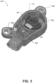
- FIG. 3 illustrates an exemplary housing 300 for the sensor arrangement 100.
- the exemplary housing 300 may be used for the housing 200 illustrated in FIG. 2 .
- the printed circuit board 104 including the magnetic sensor 102 and the pole element 106, is held firmly in place within the housing 300.
- the magnet holding element 110 including the movable magnet 108 may be disposed in an opening 302 of the housing 300.
- the magnet holding element 110 may rotate within the opening 302.
- Mounting bodies 304 and 306 are provided on the housing 300. The mounting bodies at 304 and 306 enable the housing 300 to be fixedly mounted to a vehicle, such as an automobile.
- FIG. 4 is a graph depicting an output of the sensor arrangement 100, based on a magnetic field distribution of the moveable magnet 108 through 70 degrees of rotation. At least the use of the pole element 106 enables the sensor arrangement 100 to realize a linearity error that is less than 2%. Further linearity compensation may be achievable through internal functionality of the magnetic sensor 102.
- FIG. 5 is a graph depicting linearity error without the use of the pole element 106 and with the use of the pole element 106. As illustrated, at least one sensor arrangement that does not use a pole element has higher linearity error compared to the linearity error of the sensor arrangement 100.
Landscapes
- Physics & Mathematics (AREA)
- General Physics & Mathematics (AREA)
- Condensed Matter Physics & Semiconductors (AREA)
- Transmission And Conversion Of Sensor Element Output (AREA)
Claims (7)
- Dispositif capteur (100), comprenant :un capteur magnétique (102) destiné à recevoir un champ magnétique,un élément polaire (106) disposé à côté du capteur magnétique (102), l'élément polaire (106) étant destiné à concentrer le champ magnétique pouvant être reçu par le capteur magnétique (102),une carte de circuit imprimé (104) disposée à l'intérieur d'un boîtier (300), le capteur magnétique (102) et l'élément polaire (106) étant montés sur la carte de circuit imprimé (104), le capteur magnétique (102) et l'élément polaire (106) étant maintenus fermement en place à l'intérieur du boîtier (300), etun aimant mobile (108) disposé à proximité du capteur magnétique (102) et de l'élément polaire (106), la rotation de l'aimant mobile (108) étant détectée par le capteur magnétique (102), amenant le capteur magnétique (102) à délivrer en sortie une valeur proportionnelle à la rotation de l'aimant mobile (108), la sortie étant en outre une sortie quotientmétrique corrélant une rotation détectée de l'aimant mobile (108) à une tension de sortie ;ledit élément polaire étant monté directement à côté du capteur magnétique monté sur la carte de circuit imprimé et étant agencé pour s'étendre longitudinalement sur la carte de circuit imprimé le long d'une direction circonférentielle par rapport à l'axe de rotation de l'aimant mobile pour attirer et concentrer le champ magnétique, réduisant ainsi une erreur de linéarité du capteur magnétique.
- Dispositif capteur (100) selon la revendication 1, comprenant en outre un élément de retenue d'aimant (110), l'aimant mobile (108) étant disposé dans l'élément de retenue d'aimant (110).
- Dispositif capteur (100) selon la revendication 2, dans lequel l'élément de retenue d'aimant (110) peut être fixé à un élément rotatif (112).
- Dispositif capteur (100) selon l'une quelconque des revendications précédentes, dans lequel l'élément polaire (106) est constitué d'un matériau ferromagnétique, ledit matériau ferromagnétique étant de préférence de l'acier.
- Dispositif capteur selon l'une quelconque des revendications précédentes, dans lequel l'aimant mobile (108) a la forme d'un pavé droit.
- Dispositif capteur (100) selon l'une quelconque des revendications précédentes, dans lequel le capteur magnétique (102) est un capteur à effet Hall.
- Véhicule comprenant un dispositif capteur (100) selon l'une quelconque des revendications précédentes.
Applications Claiming Priority (1)
| Application Number | Priority Date | Filing Date | Title |
|---|---|---|---|
| PCT/CN2016/093497 WO2018023693A1 (fr) | 2016-08-05 | 2016-08-05 | Circuit magnétique de détection de position angulaire |
Publications (3)
| Publication Number | Publication Date |
|---|---|
| EP3494367A1 EP3494367A1 (fr) | 2019-06-12 |
| EP3494367A4 EP3494367A4 (fr) | 2020-04-01 |
| EP3494367B1 true EP3494367B1 (fr) | 2024-06-26 |
Family
ID=61072488
Family Applications (1)
| Application Number | Title | Priority Date | Filing Date |
|---|---|---|---|
| EP16911289.3A Active EP3494367B1 (fr) | 2016-08-05 | 2016-08-05 | Capteur magnétique de position angulaire |
Country Status (4)
| Country | Link |
|---|---|
| US (1) | US11391557B2 (fr) |
| EP (1) | EP3494367B1 (fr) |
| CN (1) | CN109642808A (fr) |
| WO (1) | WO2018023693A1 (fr) |
Families Citing this family (3)
| Publication number | Priority date | Publication date | Assignee | Title |
|---|---|---|---|---|
| US11796556B2 (en) | 2018-09-19 | 2023-10-24 | Suzhou Littelfuse Ovs Co., Ltd. | Speed sensor assembly |
| WO2021000294A1 (fr) * | 2019-07-03 | 2021-01-07 | Hamlin Electronics (Suzhou) Ltd. | Appareil de détection de mouvement angulaire d'une aube ferromagnétique |
| ES3024986T3 (en) * | 2021-07-12 | 2025-06-05 | Gsr Ventiltechnik Gmbh & Co Kg | End position sensor for solenoid valve |
Family Cites Families (16)
| Publication number | Priority date | Publication date | Assignee | Title |
|---|---|---|---|---|
| US5757181A (en) | 1992-06-22 | 1998-05-26 | Durakool Incorporated | Electronic circuit for automatically compensating for errors in a sensor with an analog output signal |
| US5811968A (en) * | 1996-01-06 | 1998-09-22 | Unisia Jecs Corporation | Rotation angle sensor |
| US6124710A (en) * | 1998-11-13 | 2000-09-26 | Cts Corporation | Rotary magnetic encoder using hall effect for detecting revolution of a shaft |
| JP4007313B2 (ja) | 2003-01-22 | 2007-11-14 | 株式会社村田製作所 | 角度センサ |
| FR2854691B1 (fr) * | 2003-05-09 | 2005-07-08 | Siemens Vdo Automotive | Capteur de position angulaire sans contact a effet hall |
| EP1642086A2 (fr) | 2003-06-25 | 2006-04-05 | Philips Intellectual Property & Standards GmbH | Agencement avec un capteur d'angle en fonction du champ magnetique |
| US7400139B2 (en) * | 2005-08-02 | 2008-07-15 | Continental Automotive Systems Us, Inc. | Contactless Hall-effect angular position sensor |
| US20100176802A1 (en) | 2005-08-16 | 2010-07-15 | Koninklijke Philips Electronics, N.V. | Portable electronic device having a rotary unit |
| FR2947902B1 (fr) | 2009-07-07 | 2011-07-22 | Moving Magnet Technologies M M T | Capteur de position absolue et multi-periodique |
| CN201830313U (zh) | 2010-09-10 | 2011-05-11 | 广东欧珀移动通信有限公司 | 一种手机的旋转机构 |
| KR20120027658A (ko) | 2010-09-13 | 2012-03-22 | 엘지이노텍 주식회사 | 토크 인덱스 센서 |
| EP2525193B1 (fr) | 2011-05-17 | 2016-03-02 | Sensata Technologies, Inc. | Capteur de proximité magnétique |
| GB2505226A (en) | 2012-08-23 | 2014-02-26 | Melexis Technologies Nv | Arrangement, method and sensor for measuring an absolute angular position using a multi-pole magnet |
| CN103673870A (zh) * | 2013-12-17 | 2014-03-26 | 哈姆林电子(苏州)有限公司 | 一种角度传感器 |
| CN204180313U (zh) * | 2014-05-15 | 2015-02-25 | 上海天剑电磁技术有限公司 | 一种用于电磁炉的非接触式旋转型功率调节装置 |
| CN204731676U (zh) | 2015-07-13 | 2015-10-28 | 浙江绍兴苏泊尔生活电器有限公司 | 调节旋钮及电器产品 |
-
2016
- 2016-08-05 US US16/322,858 patent/US11391557B2/en active Active
- 2016-08-05 EP EP16911289.3A patent/EP3494367B1/fr active Active
- 2016-08-05 CN CN201680088322.3A patent/CN109642808A/zh active Pending
- 2016-08-05 WO PCT/CN2016/093497 patent/WO2018023693A1/fr not_active Ceased
Also Published As
| Publication number | Publication date |
|---|---|
| CN109642808A (zh) | 2019-04-16 |
| EP3494367A1 (fr) | 2019-06-12 |
| EP3494367A4 (fr) | 2020-04-01 |
| US11391557B2 (en) | 2022-07-19 |
| WO2018023693A1 (fr) | 2018-02-08 |
| US20210333086A1 (en) | 2021-10-28 |
Similar Documents
| Publication | Publication Date | Title |
|---|---|---|
| CN102686980B (zh) | 用于检测运动元件位移的磁场传感器装置 | |
| CN102187181B (zh) | 用于检测旋转部件的旋转位置的传感装置 | |
| US8183857B2 (en) | Rotation angle detection device for detecting rotation angle of a rotating body | |
| US8966978B2 (en) | Sensor arrangement for determining an angle of rotation | |
| US20120105057A1 (en) | Hall-effect sensor arrangement | |
| US10508897B2 (en) | Magnet device and position sensing system | |
| CN103842786B (zh) | 传感器装置 | |
| JP5412194B2 (ja) | 相対角度検出装置及びパワーステアリング装置 | |
| EP3494367B1 (fr) | Capteur magnétique de position angulaire | |
| CN103443591A (zh) | 用于求得角位置的方法 | |
| WO2008075623A1 (fr) | Détecteur d'angle de rotation | |
| JP5724326B2 (ja) | センサ付き転がり軸受及びセンサ付き転がり軸受を使用した自動車、鉄道車両、製鉄設備、工作機械 | |
| JP5469937B2 (ja) | 相対角度検出装置及びパワーステアリング装置 | |
| US20030137293A1 (en) | Path sensor with an electromagnetic converter element | |
| JP2007263585A (ja) | 回転角度検出装置 | |
| JP2018105757A (ja) | 磁気エンコーダ装置 | |
| US20030137291A1 (en) | Angle sensor with a magnetoelectrical converter element | |
| JP2018048870A (ja) | 回転角度検出装置 | |
| KR20160029989A (ko) | 토크 센서 장치 | |
| US20090278530A1 (en) | Sensor system | |
| JP2007078534A (ja) | 磁気式エンコーダ装置 | |
| JP3254892U (ja) | トリガスイッチ、電動工具及びコントローラー | |
| JP2014065367A (ja) | 回転角度・トルク検出装置 | |
| JP2025520421A (ja) | 磁気信号装置及び該装置を備えた部品 | |
| JP2011215070A (ja) | 回転角検出装置 |
Legal Events
| Date | Code | Title | Description |
|---|---|---|---|
| STAA | Information on the status of an ep patent application or granted ep patent |
Free format text: STATUS: THE INTERNATIONAL PUBLICATION HAS BEEN MADE |
|
| PUAI | Public reference made under article 153(3) epc to a published international application that has entered the european phase |
Free format text: ORIGINAL CODE: 0009012 |
|
| STAA | Information on the status of an ep patent application or granted ep patent |
Free format text: STATUS: REQUEST FOR EXAMINATION WAS MADE |
|
| 17P | Request for examination filed |
Effective date: 20190304 |
|
| AK | Designated contracting states |
Kind code of ref document: A1 Designated state(s): AL AT BE BG CH CY CZ DE DK EE ES FI FR GB GR HR HU IE IS IT LI LT LU LV MC MK MT NL NO PL PT RO RS SE SI SK SM TR |
|
| AX | Request for extension of the european patent |
Extension state: BA ME |
|
| DAV | Request for validation of the european patent (deleted) | ||
| DAX | Request for extension of the european patent (deleted) | ||
| A4 | Supplementary search report drawn up and despatched |
Effective date: 20200228 |
|
| RIC1 | Information provided on ipc code assigned before grant |
Ipc: G01B 7/30 20060101ALI20200224BHEP Ipc: G01D 5/14 20060101AFI20200224BHEP |
|
| RAP1 | Party data changed (applicant data changed or rights of an application transferred) |
Owner name: SUZHOU LITTELFUSE OVS CO., LTD. |
|
| STAA | Information on the status of an ep patent application or granted ep patent |
Free format text: STATUS: EXAMINATION IS IN PROGRESS |
|
| 17Q | First examination report despatched |
Effective date: 20220225 |
|
| GRAP | Despatch of communication of intention to grant a patent |
Free format text: ORIGINAL CODE: EPIDOSNIGR1 |
|
| STAA | Information on the status of an ep patent application or granted ep patent |
Free format text: STATUS: GRANT OF PATENT IS INTENDED |
|
| RIC1 | Information provided on ipc code assigned before grant |
Ipc: G01R 33/09 20060101ALI20231013BHEP Ipc: G01R 33/07 20060101ALI20231013BHEP Ipc: G01R 33/00 20060101ALI20231013BHEP Ipc: G01B 7/30 20060101ALI20231013BHEP Ipc: G01D 5/14 20060101AFI20231013BHEP |
|
| RIN1 | Information on inventor provided before grant (corrected) |
Inventor name: YU, JIAO Inventor name: LI, MING Inventor name: ANASTASIADIS, LOANNIS |
|
| INTG | Intention to grant announced |
Effective date: 20231031 |
|
| GRAS | Grant fee paid |
Free format text: ORIGINAL CODE: EPIDOSNIGR3 |
|
| GRAA | (expected) grant |
Free format text: ORIGINAL CODE: 0009210 |
|
| STAA | Information on the status of an ep patent application or granted ep patent |
Free format text: STATUS: THE PATENT HAS BEEN GRANTED |
|
| GRAJ | Information related to disapproval of communication of intention to grant by the applicant or resumption of examination proceedings by the epo deleted |
Free format text: ORIGINAL CODE: EPIDOSDIGR1 |
|
| GRAL | Information related to payment of fee for publishing/printing deleted |
Free format text: ORIGINAL CODE: EPIDOSDIGR3 |
|
| PUAC | Information related to the publication of a b1 document modified or deleted |
Free format text: ORIGINAL CODE: 0009299EPPU |
|
| STAA | Information on the status of an ep patent application or granted ep patent |
Free format text: STATUS: EXAMINATION IS IN PROGRESS |
|
| AK | Designated contracting states |
Kind code of ref document: B1 Designated state(s): AL AT BE BG CH CY CZ DE DK EE ES FI FR GB GR HR HU IE IS IT LI LT LU LV MC MK MT NL NO PL PT RO RS SE SI SK SM TR |
|
| REG | Reference to a national code |
Ref country code: GB Ref legal event code: FG4D |
|
| DB1 | Publication of patent cancelled |
Effective date: 20240308 |
|
| INTC | Intention to grant announced (deleted) | ||
| REG | Reference to a national code |
Ref country code: IE Ref legal event code: FG4D |
|
| GRAP | Despatch of communication of intention to grant a patent |
Free format text: ORIGINAL CODE: EPIDOSNIGR1 |
|
| STAA | Information on the status of an ep patent application or granted ep patent |
Free format text: STATUS: GRANT OF PATENT IS INTENDED |
|
| GRAS | Grant fee paid |
Free format text: ORIGINAL CODE: EPIDOSNIGR3 |
|
| GRAA | (expected) grant |
Free format text: ORIGINAL CODE: 0009210 |
|
| STAA | Information on the status of an ep patent application or granted ep patent |
Free format text: STATUS: THE PATENT HAS BEEN GRANTED |
|
| INTG | Intention to grant announced |
Effective date: 20240503 |
|
| AK | Designated contracting states |
Kind code of ref document: B1 Designated state(s): AL AT BE BG CH CY CZ DE DK EE ES FI FR GB GR HR HU IE IS IT LI LT LU LV MC MK MT NL NO PL PT RO RS SE SI SK SM TR |
|
| REG | Reference to a national code |
Ref country code: GB Ref legal event code: FG4D |
|
| REG | Reference to a national code |
Ref country code: CH Ref legal event code: EP |
|
| REG | Reference to a national code |
Ref country code: DE Ref legal event code: R096 Ref document number: 602016086752 Country of ref document: DE |
|
| P01 | Opt-out of the competence of the unified patent court (upc) registered |
Free format text: CASE NUMBER: APP_36011/2024 Effective date: 20240617 |
|
| PG25 | Lapsed in a contracting state [announced via postgrant information from national office to epo] |
Ref country code: IS Free format text: LAPSE BECAUSE OF FAILURE TO SUBMIT A TRANSLATION OF THE DESCRIPTION OR TO PAY THE FEE WITHIN THE PRESCRIBED TIME-LIMIT Effective date: 20240803 |
|
| PG25 | Lapsed in a contracting state [announced via postgrant information from national office to epo] |
Ref country code: BG Free format text: LAPSE BECAUSE OF FAILURE TO SUBMIT A TRANSLATION OF THE DESCRIPTION OR TO PAY THE FEE WITHIN THE PRESCRIBED TIME-LIMIT Effective date: 20240626 |
|
| PG25 | Lapsed in a contracting state [announced via postgrant information from national office to epo] |
Ref country code: FI Free format text: LAPSE BECAUSE OF FAILURE TO SUBMIT A TRANSLATION OF THE DESCRIPTION OR TO PAY THE FEE WITHIN THE PRESCRIBED TIME-LIMIT Effective date: 20240626 Ref country code: HR Free format text: LAPSE BECAUSE OF FAILURE TO SUBMIT A TRANSLATION OF THE DESCRIPTION OR TO PAY THE FEE WITHIN THE PRESCRIBED TIME-LIMIT Effective date: 20240626 |
|
| PGFP | Annual fee paid to national office [announced via postgrant information from national office to epo] |
Ref country code: DE Payment date: 20240703 Year of fee payment: 9 |
|
| REG | Reference to a national code |
Ref country code: LT Ref legal event code: MG9D |
|
| PG25 | Lapsed in a contracting state [announced via postgrant information from national office to epo] |
Ref country code: GR Free format text: LAPSE BECAUSE OF FAILURE TO SUBMIT A TRANSLATION OF THE DESCRIPTION OR TO PAY THE FEE WITHIN THE PRESCRIBED TIME-LIMIT Effective date: 20240704 |
|
| PGFP | Annual fee paid to national office [announced via postgrant information from national office to epo] |
Ref country code: GB Payment date: 20240704 Year of fee payment: 9 |
|
| PGFP | Annual fee paid to national office [announced via postgrant information from national office to epo] |
Ref country code: FR Payment date: 20240708 Year of fee payment: 9 |
|
| REG | Reference to a national code |
Ref country code: NL Ref legal event code: MP Effective date: 20240626 |
|
| PG25 | Lapsed in a contracting state [announced via postgrant information from national office to epo] |
Ref country code: NO Free format text: LAPSE BECAUSE OF FAILURE TO SUBMIT A TRANSLATION OF THE DESCRIPTION OR TO PAY THE FEE WITHIN THE PRESCRIBED TIME-LIMIT Effective date: 20240703 Ref country code: IS Free format text: LAPSE BECAUSE OF FAILURE TO SUBMIT A TRANSLATION OF THE DESCRIPTION OR TO PAY THE FEE WITHIN THE PRESCRIBED TIME-LIMIT Effective date: 20240803 Ref country code: HR Free format text: LAPSE BECAUSE OF FAILURE TO SUBMIT A TRANSLATION OF THE DESCRIPTION OR TO PAY THE FEE WITHIN THE PRESCRIBED TIME-LIMIT Effective date: 20240626 Ref country code: GR Free format text: LAPSE BECAUSE OF FAILURE TO SUBMIT A TRANSLATION OF THE DESCRIPTION OR TO PAY THE FEE WITHIN THE PRESCRIBED TIME-LIMIT Effective date: 20240704 Ref country code: FI Free format text: LAPSE BECAUSE OF FAILURE TO SUBMIT A TRANSLATION OF THE DESCRIPTION OR TO PAY THE FEE WITHIN THE PRESCRIBED TIME-LIMIT Effective date: 20240626 Ref country code: BG Free format text: LAPSE BECAUSE OF FAILURE TO SUBMIT A TRANSLATION OF THE DESCRIPTION OR TO PAY THE FEE WITHIN THE PRESCRIBED TIME-LIMIT Effective date: 20240626 |
|
| PG25 | Lapsed in a contracting state [announced via postgrant information from national office to epo] |
Ref country code: NL Free format text: LAPSE BECAUSE OF FAILURE TO SUBMIT A TRANSLATION OF THE DESCRIPTION OR TO PAY THE FEE WITHIN THE PRESCRIBED TIME-LIMIT Effective date: 20240626 |
|
| PG25 | Lapsed in a contracting state [announced via postgrant information from national office to epo] |
Ref country code: NL Free format text: LAPSE BECAUSE OF FAILURE TO SUBMIT A TRANSLATION OF THE DESCRIPTION OR TO PAY THE FEE WITHIN THE PRESCRIBED TIME-LIMIT Effective date: 20240626 |
|
| PG25 | Lapsed in a contracting state [announced via postgrant information from national office to epo] |
Ref country code: PT Free format text: LAPSE BECAUSE OF FAILURE TO SUBMIT A TRANSLATION OF THE DESCRIPTION OR TO PAY THE FEE WITHIN THE PRESCRIBED TIME-LIMIT Effective date: 20241028 |
|
| PG25 | Lapsed in a contracting state [announced via postgrant information from national office to epo] |
Ref country code: PT Free format text: LAPSE BECAUSE OF FAILURE TO SUBMIT A TRANSLATION OF THE DESCRIPTION OR TO PAY THE FEE WITHIN THE PRESCRIBED TIME-LIMIT Effective date: 20241028 |
|
| REG | Reference to a national code |
Ref country code: AT Ref legal event code: MK05 Ref document number: 1672805 Country of ref document: AT Kind code of ref document: T Effective date: 20240626 |
|
| PG25 | Lapsed in a contracting state [announced via postgrant information from national office to epo] |
Ref country code: EE Free format text: LAPSE BECAUSE OF FAILURE TO SUBMIT A TRANSLATION OF THE DESCRIPTION OR TO PAY THE FEE WITHIN THE PRESCRIBED TIME-LIMIT Effective date: 20240626 |
|
| PG25 | Lapsed in a contracting state [announced via postgrant information from national office to epo] |
Ref country code: AT Free format text: LAPSE BECAUSE OF FAILURE TO SUBMIT A TRANSLATION OF THE DESCRIPTION OR TO PAY THE FEE WITHIN THE PRESCRIBED TIME-LIMIT Effective date: 20240626 |
|
| PG25 | Lapsed in a contracting state [announced via postgrant information from national office to epo] |
Ref country code: CZ Free format text: LAPSE BECAUSE OF FAILURE TO SUBMIT A TRANSLATION OF THE DESCRIPTION OR TO PAY THE FEE WITHIN THE PRESCRIBED TIME-LIMIT Effective date: 20240626 |
|
| PG25 | Lapsed in a contracting state [announced via postgrant information from national office to epo] |
Ref country code: RO Free format text: LAPSE BECAUSE OF FAILURE TO SUBMIT A TRANSLATION OF THE DESCRIPTION OR TO PAY THE FEE WITHIN THE PRESCRIBED TIME-LIMIT Effective date: 20240626 |
|
| PG25 | Lapsed in a contracting state [announced via postgrant information from national office to epo] |
Ref country code: ES Free format text: LAPSE BECAUSE OF FAILURE TO SUBMIT A TRANSLATION OF THE DESCRIPTION OR TO PAY THE FEE WITHIN THE PRESCRIBED TIME-LIMIT Effective date: 20240626 Ref country code: SM Free format text: LAPSE BECAUSE OF FAILURE TO SUBMIT A TRANSLATION OF THE DESCRIPTION OR TO PAY THE FEE WITHIN THE PRESCRIBED TIME-LIMIT Effective date: 20240626 |
|
| PG25 | Lapsed in a contracting state [announced via postgrant information from national office to epo] |
Ref country code: SM Free format text: LAPSE BECAUSE OF FAILURE TO SUBMIT A TRANSLATION OF THE DESCRIPTION OR TO PAY THE FEE WITHIN THE PRESCRIBED TIME-LIMIT Effective date: 20240626 Ref country code: RO Free format text: LAPSE BECAUSE OF FAILURE TO SUBMIT A TRANSLATION OF THE DESCRIPTION OR TO PAY THE FEE WITHIN THE PRESCRIBED TIME-LIMIT Effective date: 20240626 Ref country code: ES Free format text: LAPSE BECAUSE OF FAILURE TO SUBMIT A TRANSLATION OF THE DESCRIPTION OR TO PAY THE FEE WITHIN THE PRESCRIBED TIME-LIMIT Effective date: 20240626 Ref country code: EE Free format text: LAPSE BECAUSE OF FAILURE TO SUBMIT A TRANSLATION OF THE DESCRIPTION OR TO PAY THE FEE WITHIN THE PRESCRIBED TIME-LIMIT Effective date: 20240626 Ref country code: CZ Free format text: LAPSE BECAUSE OF FAILURE TO SUBMIT A TRANSLATION OF THE DESCRIPTION OR TO PAY THE FEE WITHIN THE PRESCRIBED TIME-LIMIT Effective date: 20240626 Ref country code: AT Free format text: LAPSE BECAUSE OF FAILURE TO SUBMIT A TRANSLATION OF THE DESCRIPTION OR TO PAY THE FEE WITHIN THE PRESCRIBED TIME-LIMIT Effective date: 20240626 |
|
| REG | Reference to a national code |
Ref country code: DE Ref legal event code: R097 Ref document number: 602016086752 Country of ref document: DE |
|
| REG | Reference to a national code |
Ref country code: CH Ref legal event code: PL |
|
| PG25 | Lapsed in a contracting state [announced via postgrant information from national office to epo] |
Ref country code: DK Free format text: LAPSE BECAUSE OF FAILURE TO SUBMIT A TRANSLATION OF THE DESCRIPTION OR TO PAY THE FEE WITHIN THE PRESCRIBED TIME-LIMIT Effective date: 20240626 |
|
| PG25 | Lapsed in a contracting state [announced via postgrant information from national office to epo] |
Ref country code: LU Free format text: LAPSE BECAUSE OF NON-PAYMENT OF DUE FEES Effective date: 20240805 |
|
| PG25 | Lapsed in a contracting state [announced via postgrant information from national office to epo] |
Ref country code: MC Free format text: LAPSE BECAUSE OF FAILURE TO SUBMIT A TRANSLATION OF THE DESCRIPTION OR TO PAY THE FEE WITHIN THE PRESCRIBED TIME-LIMIT Effective date: 20240626 Ref country code: CH Free format text: LAPSE BECAUSE OF NON-PAYMENT OF DUE FEES Effective date: 20240831 |
|
| PG25 | Lapsed in a contracting state [announced via postgrant information from national office to epo] |
Ref country code: SK Free format text: LAPSE BECAUSE OF FAILURE TO SUBMIT A TRANSLATION OF THE DESCRIPTION OR TO PAY THE FEE WITHIN THE PRESCRIBED TIME-LIMIT Effective date: 20240626 |
|
| PLBE | No opposition filed within time limit |
Free format text: ORIGINAL CODE: 0009261 |
|
| STAA | Information on the status of an ep patent application or granted ep patent |
Free format text: STATUS: NO OPPOSITION FILED WITHIN TIME LIMIT |
|
| 26N | No opposition filed |
Effective date: 20250327 |
|
| PG25 | Lapsed in a contracting state [announced via postgrant information from national office to epo] |
Ref country code: RS Free format text: LAPSE BECAUSE OF FAILURE TO SUBMIT A TRANSLATION OF THE DESCRIPTION OR TO PAY THE FEE WITHIN THE PRESCRIBED TIME-LIMIT Effective date: 20240626 |
|
| REG | Reference to a national code |
Ref country code: BE Ref legal event code: MM Effective date: 20240831 |
|
| PG25 | Lapsed in a contracting state [announced via postgrant information from national office to epo] |
Ref country code: BE Free format text: LAPSE BECAUSE OF NON-PAYMENT OF DUE FEES Effective date: 20240831 Ref country code: IT Free format text: LAPSE BECAUSE OF NON-PAYMENT OF DUE FEES Effective date: 20240805 |
|
| PG25 | Lapsed in a contracting state [announced via postgrant information from national office to epo] |
Ref country code: IE Free format text: LAPSE BECAUSE OF NON-PAYMENT OF DUE FEES Effective date: 20240805 |
|
| PG25 | Lapsed in a contracting state [announced via postgrant information from national office to epo] |
Ref country code: LV Free format text: LAPSE BECAUSE OF FAILURE TO SUBMIT A TRANSLATION OF THE DESCRIPTION OR TO PAY THE FEE WITHIN THE PRESCRIBED TIME-LIMIT Effective date: 20240626 |
|
| PG25 | Lapsed in a contracting state [announced via postgrant information from national office to epo] |
Ref country code: SE Free format text: LAPSE BECAUSE OF FAILURE TO SUBMIT A TRANSLATION OF THE DESCRIPTION OR TO PAY THE FEE WITHIN THE PRESCRIBED TIME-LIMIT Effective date: 20240626 |
|
| PG25 | Lapsed in a contracting state [announced via postgrant information from national office to epo] |
Ref country code: CY Free format text: LAPSE BECAUSE OF FAILURE TO SUBMIT A TRANSLATION OF THE DESCRIPTION OR TO PAY THE FEE WITHIN THE PRESCRIBED TIME-LIMIT; INVALID AB INITIO Effective date: 20160805 |
|
| REG | Reference to a national code |
Ref country code: DE Ref legal event code: R119 Ref document number: 602016086752 Country of ref document: DE |
|
| PG25 | Lapsed in a contracting state [announced via postgrant information from national office to epo] |
Ref country code: HU Free format text: LAPSE BECAUSE OF FAILURE TO SUBMIT A TRANSLATION OF THE DESCRIPTION OR TO PAY THE FEE WITHIN THE PRESCRIBED TIME-LIMIT; INVALID AB INITIO Effective date: 20160805 |