EP3494589B1 - Ensemble et procédé de commutation de hautes tensions - Google Patents
Ensemble et procédé de commutation de hautes tensions Download PDFInfo
- Publication number
- EP3494589B1 EP3494589B1 EP17764543.9A EP17764543A EP3494589B1 EP 3494589 B1 EP3494589 B1 EP 3494589B1 EP 17764543 A EP17764543 A EP 17764543A EP 3494589 B1 EP3494589 B1 EP 3494589B1
- Authority
- EP
- European Patent Office
- Prior art keywords
- switching
- units
- elements
- coupling element
- drive
- Prior art date
- Legal status (The legal status is an assumption and is not a legal conclusion. Google has not performed a legal analysis and makes no representation as to the accuracy of the status listed.)
- Revoked
Links
- 238000000034 method Methods 0.000 title claims description 20
- 230000008878 coupling Effects 0.000 claims description 70
- 238000010168 coupling process Methods 0.000 claims description 70
- 238000005859 coupling reaction Methods 0.000 claims description 70
- 230000010355 oscillation Effects 0.000 claims description 22
- 239000012212 insulator Substances 0.000 claims description 15
- 229910052751 metal Inorganic materials 0.000 claims description 14
- 239000002184 metal Substances 0.000 claims description 14
- 230000008569 process Effects 0.000 claims description 9
- IJGRMHOSHXDMSA-UHFFFAOYSA-N Atomic nitrogen Chemical compound N#N IJGRMHOSHXDMSA-UHFFFAOYSA-N 0.000 claims description 8
- CURLTUGMZLYLDI-UHFFFAOYSA-N Carbon dioxide Chemical compound O=C=O CURLTUGMZLYLDI-UHFFFAOYSA-N 0.000 claims description 8
- 239000003990 capacitor Substances 0.000 claims description 6
- 229910000831 Steel Inorganic materials 0.000 claims description 4
- 229910052782 aluminium Inorganic materials 0.000 claims description 4
- XAGFODPZIPBFFR-UHFFFAOYSA-N aluminium Chemical compound [Al] XAGFODPZIPBFFR-UHFFFAOYSA-N 0.000 claims description 4
- 229910002092 carbon dioxide Inorganic materials 0.000 claims description 4
- 239000001569 carbon dioxide Substances 0.000 claims description 4
- 239000012530 fluid Substances 0.000 claims description 4
- IYRWEQXVUNLMAY-UHFFFAOYSA-N fluoroketone group Chemical group FC(=O)F IYRWEQXVUNLMAY-UHFFFAOYSA-N 0.000 claims description 4
- 239000007789 gas Substances 0.000 claims description 4
- 239000007788 liquid Substances 0.000 claims description 4
- 229910052757 nitrogen Inorganic materials 0.000 claims description 4
- 239000010959 steel Substances 0.000 claims description 4
- 230000005540 biological transmission Effects 0.000 claims description 3
- 239000000919 ceramic Substances 0.000 claims description 3
- 229920001296 polysiloxane Polymers 0.000 claims description 3
- 239000002131 composite material Substances 0.000 claims description 2
- 238000010276 construction Methods 0.000 claims 2
- 230000001360 synchronised effect Effects 0.000 description 10
- 238000004146 energy storage Methods 0.000 description 2
- 238000004519 manufacturing process Methods 0.000 description 2
- 230000006641 stabilisation Effects 0.000 description 2
- 238000011105 stabilization Methods 0.000 description 2
- 238000004026 adhesive bonding Methods 0.000 description 1
- 230000008859 change Effects 0.000 description 1
- 230000001419 dependent effect Effects 0.000 description 1
- 230000007613 environmental effect Effects 0.000 description 1
- 238000009434 installation Methods 0.000 description 1
- 239000011810 insulating material Substances 0.000 description 1
- 230000007257 malfunction Effects 0.000 description 1
- 230000007246 mechanism Effects 0.000 description 1
- 230000005405 multipole Effects 0.000 description 1
- 230000001105 regulatory effect Effects 0.000 description 1
- 230000001960 triggered effect Effects 0.000 description 1
- 238000003466 welding Methods 0.000 description 1
Images
Classifications
-
- H—ELECTRICITY
- H01—ELECTRIC ELEMENTS
- H01H—ELECTRIC SWITCHES; RELAYS; SELECTORS; EMERGENCY PROTECTIVE DEVICES
- H01H33/00—High-tension or heavy-current switches with arc-extinguishing or arc-preventing means
- H01H33/02—Details
- H01H33/04—Means for extinguishing or preventing arc between current-carrying parts
- H01H33/14—Multiple main contacts for the purpose of dividing the current through, or potential drop along, the arc
-
- H—ELECTRICITY
- H01—ELECTRIC ELEMENTS
- H01H—ELECTRIC SWITCHES; RELAYS; SELECTORS; EMERGENCY PROTECTIVE DEVICES
- H01H33/00—High-tension or heavy-current switches with arc-extinguishing or arc-preventing means
- H01H33/008—Pedestal mounted switch gear combinations
-
- H—ELECTRICITY
- H01—ELECTRIC ELEMENTS
- H01H—ELECTRIC SWITCHES; RELAYS; SELECTORS; EMERGENCY PROTECTIVE DEVICES
- H01H33/00—High-tension or heavy-current switches with arc-extinguishing or arc-preventing means
- H01H33/02—Details
- H01H33/28—Power arrangements internal to the switch for operating the driving mechanism
-
- H—ELECTRICITY
- H01—ELECTRIC ELEMENTS
- H01H—ELECTRIC SWITCHES; RELAYS; SELECTORS; EMERGENCY PROTECTIVE DEVICES
- H01H33/00—High-tension or heavy-current switches with arc-extinguishing or arc-preventing means
- H01H33/02—Details
- H01H33/46—Interlocking mechanisms
- H01H33/52—Interlocking mechanisms for interlocking two or more switches
Definitions
- the invention relates to an arrangement and a method for switching high voltages with a contact gap which comprises at least two switching units connected in series.
- Each switching unit comprises at least one support element and elements of a kinematic chain for transmitting a switching movement from at least one drive.
- circuit breakers for switching high voltages such. B. from the DE 12 11 703 B known, in particular for switching voltages in the range from 70 kV to 1200 kV.
- circuit breakers These have contacts with fixed and/or movable contact pieces, in particular rated current and arcing contact pieces, with arcing occurring and being able to be extinguished when switching.
- the interrupter units ie circuit breakers, close or disconnect at least one current path, in particular one current path per pole.
- a three-pole arrangement with at least three circuit breakers, in particular at least one circuit breaker per pole is z. B. designed to switch three current paths individually, together in succession or simultaneously, ie to separate or close.
- Switching is regulated or controlled, e.g. B. depending on measured variables of the arrangement and / or according to the energy demand.
- Appropriate facilities such as B. current-voltage measuring devices, sensors for temperature, air pressure or malfunctions can be included in the arrangements for switching high voltages, z. B. to decentralized or to control switching centrally, in particular from a control room.
- a switching arrangement can comprise a plurality of interrupter units per pole, in particular electrically connected in series one behind the other.
- a quadruple-break arrangement may comprise four breaker units connected in series, whereby e.g. B. a switching voltage of 1200 V is reduced to a voltage of 300 V per interrupter unit.
- the modular structure with several interrupter units enables the arrangement to be adapted inexpensively to the required maximum switching capacity, the use of interrupter units that are technically simple and inexpensive to implement, with a lower maximum switching capacity or voltage, and a compact structure.
- the interrupter units connected in series must be synchronous when switching, i. H. switch essentially simultaneously.
- a drive provides the kinetic energy required for the shifting process.
- a drive z. B a spring-loaded drive with at least one energy storage spring and / or an electric motor can be used. Hand cranks and/or a motor can be used to supply the energy to an energy storage spring, which stores it until the time of shifting.
- Multi-pole switches can have at least one drive per pole, or a common drive for several poles.
- a stored energy mechanism comprises at least one closing spring and at least one opening spring, or a common spring for the closing and opening movement.
- Elements of the kinematic chain transfer the kinetic energy from the drive to the moving contact pieces electrical contacts when switching.
- Transmission elements such. B. shafts and levers can be included to change the direction of movement and force, which z. B. be transferred to the movable contacts via a switching rod.
- Fast switching especially in the millisecond range, requires large forces and fast movements.
- Synchronous switching requires synchronism, ie simultaneous switching of all interrupter units connected in series.
- Standards require a maximum time deviation, ie synchronization during a switch-on process, which is within one-sixth of an oscillation cycle of the voltage oscillation applied to the arrangement. During a turn-off operation, the standards require all interrupter units to be synchronized to within one eighth of a cycle of the voltage swing applied to the assembly.
- the interrupter units are arranged on supports or supporting elements.
- Supporting elements include z. B. insulators made of ceramic and / or silicone, which in particular on metal supports such. B. made of steel or aluminum, are arranged on a foundation.
- the supporting elements can be in the form of a column and arranged perpendicularly to the plane of the foundation will.
- two interrupter units can be combined into a switching unit or switching head and arranged symmetrically on a carrier.
- the interrupter units can be arranged one behind the other along their longitudinal axis, electrically connected in series, and attached to the upper end, ie the end facing away from the foundation, of a support element in a mechanically stable manner.
- a carrier with the switching unit arranged thereon forms z.
- B. a T-shape wherein the longitudinal axis of the switching unit runs in particular substantially parallel to the foundation.
- a pole of a quadruple-breaking arrangement comprises e.g. B. two supporting elements, each with a switch head located thereon.
- the switching heads are arranged relative to one another in such a way that their longitudinal axes lie on a common longitudinal axis, and all four interrupter units are connected to one another in series.
- Each support element with switching head has a drive and elements of a kinematic chain for transmitting the switching movement from the drive to the respective switching head.
- Synchronous switching requires electrical synchronization of the two drives in particular, which should compensate for differences in the drives, kinematic chains and interrupter units in order to ensure synchronization when switching. Adjusting the electrical synchronization is complex, time-consuming and costly.
- the object of the present invention is to avoid or reduce the problems described above.
- it is an object to specify an arrangement and a method for switching high voltages, which allow simple and inexpensive synchronization of interrupter units when switching.
- An arrangement according to the invention for switching high voltages comprises a switching path which has at least two switching units connected in series, each switching unit comprising at least one support element and elements of a kinematic chain for transmitting a switching movement from at least one drive.
- the supporting elements of the at least two switching units are mechanically connected to one another via at least one coupling element.
- the drive of the at least two switching units is designed as a common drive. Differences in height in the foundation are compensated for by supporting elements of different lengths.
- the at least one coupling element is arranged on the support elements in such a way that the distance from the drive to the switching units via elements of the kinematic chain is the same length, with height differences in the foundation with the same distances between the switching units and attachment points of the at least one coupling element on the support elements.
- the coupling element enables a mechanical connection of the at least two switching units connected in series.
- a mechanical adjustment of synchronization or synchronism of the switching units is thereby possible, in particular by changing the distance between the at least one drive and at least one switching unit via elements of the kinematic chain, which are arranged on or in the coupling element and/or support element.
- the coupling element also leads to a mechanical stabilization of the support elements in that they support each other via the at least one support element. Especially when there is a risk of earthquakes and/or other weather conditions, such as e.g. B. storm, a high mechanical stability is necessary.
- Each switching unit can have at least two interrupter units in the manner of a circuit breaker, in particular with electrical resistance and/or capacitor units.
- a quadruple-breaking arrangement is easy to produce by using two switching units, each arranged on a support element, each with two interrupter units and in particular other electrical units such.
- the two support elements are mechanically coupled to one another via the coupling element, and the switching units assigned to the support elements can be synchronized in terms of switching with the aid of the coupling element. In this case, a high voltage can be switched simply and inexpensively by means of the four circuit breakers, resistor units and/or capacitor units in particular, with circuit breakers connected in series.
- the at least one coupling element can have at least one carrier, in particular a transverse carrier, which connects the carrier elements of the at least two switching units to one another.
- a cross member can easily and inexpensively compensate for differences in height, e.g. B. the support elements of the switching units, so that the distance of the at least one drive to the switching units or interrupter units is the same to ensure a certain minimum synchronization.
- the supporting elements of the at least two switching units can be arranged perpendicularly to a foundation, in particular parallel to one another, with the switching units each arranged on the supporting elements at one end of the supporting elements on the side facing away from the foundation.
- the at least one coupling element can be arranged in a lower area of the support elements, in particular parallel to the foundation. This arrangement is mechanically stable due to the stiffening via the coupling element. As described above, by arranging the coupling element parallel to the foundation, height differences e.g. B. the supporting elements of the switching units are compensated.
- the drive of the at least two switching units can be designed as a common drive, in particular arranged on at least one coupling element.
- the drive can be arranged centrally between the at least two switching units and/or center axes of the support elements. Due to the central arrangement between the two switching units on the coupling element, the distance between the drive and the switching units is the same, i. H. a good mechanical synchronization of the switching of the two switching units is possible.
- the arrangement may be mirror symmetrical, with a mirror axis running perpendicularly through the central drive. Identical elements of the kinematic chain for both switching units enable high synchronism, i. H. Simultaneous switching of the switching units with a small maximum difference in the switching time.
- the drive can B. be a spring-loaded drive, especially with closing and opening. As a result, an arrangement for switching with a high degree of synchronism can be implemented inexpensively using simple means.
- the at least two switching units can be arranged one behind the other along a common longitudinal axis, in particular with at least four interrupter units arranged one behind the other along the common longitudinal axis and in particular electrically connected in series.
- the longitudinal axis can be essentially parallel to the foundation.
- the supporting element of a respective switching unit can be arranged in the middle of the switching unit, in particular with the same number of interrupter units on both sides of the supporting element of the respective switching unit.
- the described structure of the arrangement according to the invention results in two T-shaped switching units with a respective support element, which result in the switching units being arranged along an axis and enable simple connection in series. Differences in height in the foundation can e.g. B.
- the coupling element z. B. at right angles to the support elements.
- the support elements can be of the same length, with a high level of synchronism being achieved by arranging the coupling element parallel to the plane of the foundation.
- the coupling element stabilizes the support elements mechanically and enables a drive, in particular a centrally arranged drive, to be arranged at the same distance from the two switching units.
- multiple drives, z. B. two can be used, which are attached to the coupling element in such a way that there is an equal distance between the drives and the two switching units via elements of the kinematic chain.
- Differences in the elements of the kinematic chains of both drives can also be compensated for by offsetting the drives to form an arrangement with the drives at the same distance from the two switching units. Synchronization can be achieved by moving one drive or both drives against each other along the coupling element. Synchronization can also be achieved by tilting the coupling element relative to the support elements, as a result of which running differences in the kinematic chains can be compensated for.
- the arrangement can be a quadruple-breaking arrangement in the manner of a circuit breaker, with four interrupter units connected in series, in particular arranged along a common longitudinal axis, with two interrupter units each being arranged on a support element and the support elements via at least one coupling element, in particular essentially with the longitudinal axis of the coupling element are arranged parallel to the common longitudinal axis of the interrupter units, are mechanically connected to one another in the manner of a web.
- a particular common drive of the interrupter units can be connected to the coupling element, e.g. B. can be arranged centrally on the coupling element.
- the structure described allows switching high voltages, especially up to 1200 V, e.g. B.
- Synchronization is achieved mechanically through the use of the coupling element, e.g. B. by changing the position of the drive on the coupling element and thus the distance between elements of the kinematic chain between the drive and the interrupter units.
- Elements of the kinematic chain can be included in the arrangement according to the invention for transmitting the switching movement from the at least one drive to the interrupter units of the at least two switching units.
- the elements of the kinematic chain can be arranged on or in the coupling element and/or on or in the support elements, and transmit the movement generated by the drive to the interrupter units as a switching movement.
- the path or the length of the path via elements of the kinematic chain on or in the support elements and/or on or in the coupling element is also determined and/or or set, whereby a high synchronization of the switching movement and the switching time can be achieved.
- the supporting elements of the at least two switching units can include insulators, in particular insulators made of silicone, composite materials and/or ceramics.
- the support elements of the at least two switching units can include metal supports, in particular made of aluminum and/or steel.
- the support elements can be composed of insulator elements and/or metal support elements.
- a supporting element can be constructed in the form of a column, with an upper area made of insulating material, in particular a ribbed cylindrical insulator, and a lower area made of a metal support, in particular a cylindrical and/or T-shaped metal support.
- the metal support can also be designed as a metal frame, and / or z. B.
- the insulators as support elements can stand up vertically, in particular as insulator columns be arranged on the metal frame.
- the switching units can be arranged on the insulator columns and elements of the kinematic chain can be movably arranged on or in the coupling element, the insulator columns and/or the metal frame.
- a drive can be arranged on the coupling element, it being possible for the coupling element to be part of the metal frame.
- An electrically insulating fluid can be included, in particular a liquid and/or a gas, in particular SF 6 , nitrogen, dry air, carbon dioxide, a fluoroketone and/or a fluoronitrile.
- the at least one insulator and/or the interrupter units can be filled with the electrically insulating fluid, in particular a liquid and/or a gas, in particular SF 6 , nitrogen, dry air, carbon dioxide, a fluoroketone and/or a fluoronitrile.
- the distance across the elements of the kinematic chain from the drive to at least two, in particular all, interrupter units can be the same, in particular with the same number and identically designed elements of the kinematic chain from the drive to each interrupter unit, in particular with a common drive for all interrupter units in the middle between the at least two switching units and arranged on the coupling element.
- support elements have different lengths, in particular to compensate for differences in height of the foundation, and the at least one coupling element is arranged on the support elements in such a way that the distance from the drive to the switching units via elements of the kinematic chain is the same length, especially in the case of height differences in the foundation with equal distances between the switching units and attachment points of the at least one coupling element on the switching units.
- a high level of synchronism is also achieved mechanically using simple, cost-effective means accessible. Synchronization can be achieved and easily readjusted via the position of the coupling element and the drive in relation to the switching units. It is possible to use a common drive for the at least two, in particular all, switching units, which reduces costs and effort.
- a method according to the invention for shifting an arrangement described above comprises that when a shifting process is triggered, kinetic energy is provided by the common drive, in particular a stored-energy spring drive, and the kinetic energy is transmitted via elements of the kinematic chain to at least two switching units, in particular four interrupter units, in particular in the manner of one Circuit breaker is transferred.
- the two switching units and/or four breaker units are electrically connected in series and each switching unit is supported on a support member.
- the at least two support elements are connected via a common coupling element, and the kinetic energy is transmitted via elements of the kinematic chain arranged in or on the support elements and/or the coupling element.
- all interrupter units can run synchronously within a sixth of an oscillation cycle of the voltage oscillation applied to the arrangement, in particular in the case of a periodically recurring oscillation, in particular a sinusoidal oscillation, with a period of 50 or 60 Hz.
- the synchronism of all interrupter units can be within an eighth of an oscillation cycle of the voltage oscillation applied to the arrangement, in particular in the case of a periodically recurring oscillation, in particular a sinusoidal oscillation, with a period of 50 or 60 Hz.
- FIGS figures 1 and 2 arrangements for switching high voltages according to the prior art and an exemplary embodiment of the invention are shown schematically in FIGS figures 1 and 2 shown and described in more detail below.
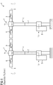
- FIG 1 shows a schematic side view of a quadruple-breaking arrangement 1 for switching high voltages according to the prior art.
- the arrangement 1 has a contact gap which comprises two switching units 2, 3 connected in series, each with two interrupter units 6 connected in series.
- the switching units 2, 3 with the interrupter units 6 are each designed in the form of a switching head which is arranged on a support element 4, 5 in each case.
- the two interrupter units 6 of a switching unit 2, 3, which are designed in the manner of a circuit breaker, are arranged spatially one behind the other along their longitudinal axis on a common axis 12 and are connected to one another via a connecting flange 14. In the area of the connecting flange 14 or over the connecting flange 14, the interrupter units 6 are attached to the respective support element 4, 5 of the switching unit 3, 4.
- the two supporting elements 4, 5 of the two switching units 2, 3 are each in the form of a column.
- the pillar is made up of different areas, e.g. B. from an insulator, which is attached to the respective connecting flange 14 of the switching unit 2, 3, and which is arranged on a metal support.
- the metal support is arranged in the lower region 11 of the column or of the supporting element 4, 5 and z. B. formed in a columnar shape and / or T-beam shape.
- the supporting elements 4, 5 are on z. B. arranged a foundation and in particular with this over z. B. screws or fixed by setting in concrete.
- the supporting elements 4, 5 are in particular essentially perpendicular to the plane of the foundation.
- the supporting elements 4, 5 each form a T-shape with the associated switching unit 2, 3, with an interrupter unit 6 of the respective switching head 2, 3 being arranged to the right and left of the supporting element 4, 5.
- the foundation is flat and horizontal, with the supporting elements 4, 5 having the same height.
- the interrupter units 6 of the two switching units 2, 3 are arranged one behind the other with their respective longitudinal axis on a common longitudinal axis 12 and are electrically connected in series.
- the arrangement 1 has electrical connections 9 in order to connect the arrangement z. B. to be electrically connected to the power grids to be switched, power generators and / or power consumers.
- a drive 8 is arranged on each support element 4 , 5 , in particular in the lower region 11 on the support element 4 , 5 .
- the drive 8 is z. B. in the form of a spring-loaded drive with a switch-on and a switch-off spring and/or a electric motor formed. When switching, the drive 8 provides the kinetic energy that is required to move the movable contact pieces of the interrupter units 6 .
- Elements of a kinematic chain 7, z. B. in the form of shafts, rods and / or gear parts are arranged on or in the support element 4, 5, for transmitting the kinetic energy from the drive 8 to the movable contacts of the interrupter units 6, ie for transmitting the switching movement when switching.
- the elements of the kinematic chain 7 are indicated schematically in the figures by dashed lines.
- the two drives 8 of the two switching units 2, 3 are electrically connected to one another and electrically synchronized in order to achieve synchronization of the interrupter units 6 of the two switching units 2, 3 when switching. Deviations or tolerances in production and installation can lead to different running times of the movement via the two kinematic chains 7 of the two switching units 2, 3 with the respective support elements 4, 5.
- standards require all interrupter units 6 to run in synchronism with a deviation in the switching times of the interrupter units 6 which is within one-sixth of an oscillation cycle of the voltage oscillation applied to the arrangement 1.
- synchronization is required, in which all interrupter units 6 switch with a deviation in the switching times of the interrupter units 6 which is within one eighth of an oscillation cycle of the voltage oscillation applied to the arrangement 1.
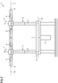
- FIG 2 is a schematic side view of a quadruple-breaking arrangements 1 according to the invention for switching high voltages.
- the arrangement 1 is analogous to the arrangement 1 of figure 1 , but with a coupling element 10 and a common drive 8 for all four interrupter units 6.
- the coupling element 10 is in the form of a web and in particular is arranged with its ends on a support element 4, 5 of the two switching units 2, 3.
- An attachment of the coupling element 10 to the support elements 4, 5 can, for. Example by screwing, welding, gluing or other connection techniques.
- the common drive 8 is arranged in the middle, ie at the same distance from the two support elements 4 and 5 and is fastened to the coupling element 10 .
- Differences in the kinematic chains 7 of the first and second switching unit 2, 3 can be compensated for by changing the position of the drive 8 on the coupling element 10 and/or the coupling element relative to the respective switching unit 2, 3, whereby the distance between the drive 8 and the two switching units 2, 3 is determined via elements of the kinematic chain 7 .
- the coupling element 10, as in figure 2 is shown, be arranged parallel to the foundation, or if there are differences between the elements of the kinematic chain 7 of the first shifting unit 2 and elements of the kinematic chain 7 of the second shifting unit 3, the differences can be compensated for by a tilted coupling element 10, ie not arranged parallel to the ground .
- the coupling element 10 is arranged on the support elements 4, 5 in such a way that transmission paths of equal length via the kinematic chain 7 from the drive 8 to the first and to the second switching unit 2, 3 are created.
- each interrupter unit 6 includes electrical resistors, capacitors and / or shields. Elongated resistors and / or capacitors can be spatially parallel to the interrupter units 6, which z. B. are in the form of a circuit breaker, are arranged.
- the coupling element 10 can be made in one piece, z. B. steel or aluminum, and / or arranged as a T-beam with elements of the kinematic chain 7 on the carrier, or as a hollow body, z. B. with a square or round cross-section, arranged with elements of the kinematic chain 7 in the carrier, be formed.
- the arrangement 1 can include more than two switching units 2, 3, each with a support element 10, connected to at least two support elements 10, in particular all support elements 10, via the coupling element 10. There can also be several Supporting elements 10 be included.
- a switching unit 2, 3 can include one, two or more interrupter units 10. So per switching unit 2, 3, as shown in the figures, two interrupter units can be arranged linearly to each other, or z. B. three interrupter units can be arranged in a Y-shape per switching unit 2, 3.
Landscapes
- Driving Mechanisms And Operating Circuits Of Arc-Extinguishing High-Tension Switches (AREA)
- Gas-Insulated Switchgears (AREA)
- Electronic Switches (AREA)
Claims (14)
- Agencement (1) pour appliquer des hautes tensions comprenant un espace de coupure, qui comprend au moins deux unités (2, 3) de coupure montées en série, dans lequel chaque unité (2, 3) de coupure comprend respectivement au moins un élément (4, 5) support et des éléments d'un chaîne (7) cinématique de transmission d'un mouvement de coupure par au moins un entraînement (8), dans lequel les éléments (4, 5) support des au moins deux unités (2, 3) de coupure sont reliés entre eux mécaniquement par au moins un élément (10) d'accouplement et l'entraînement (8) des au moins deux unités (2, 3) de coupure est constitué sous la forme d'un entraînement (8) commun,
caractérisé en ce que
des éléments (4, 5) support ont une longueur différente pour compenser des différences de niveau de la fondation et en ce que le au moins un élément (10) d'accouplement est monté sur les éléments (4, 5) support de manière à ce que la distance de l'entraînement (8) aux éléments (2, 3) de coupure ait, par des éléments de la chaîne (7) cinématique, la même longueur, pour des différences de niveau de la fondation avec des distances de même longueur des unités (2, 3) de coupure à des points de fixation du au moins un élément (10) d'accouplement sur les éléments (4, 5) support. - Agencement (1) suivant la revendication 1, caractérisé en ce que chaque unité (2, 3) de coupure a au moins deux unités (6) d'interruption à la manière d'un disjoncteur ayant des unités électriques de résistance et/ou de condensateur.
- Agencement (1) suivant l'une des revendications précédentes, caractérisé en ce que le au moins un élément (10) d'accouplement a au moins une traverse, qui relie entre eux les éléments (4, 5) support des au moins deux unités (2, 3) de coupure.
- Agencement (1) suivant l'une des revendications précédentes, caractérisé en ce que les éléments (4, 5) support des au moins deux unités (2, 3) de coupure sont disposés perpendiculairement à une fondation, en étant notamment parallèles entre eux, avec les unités (2, 3) de coupure respectivement sur les éléments (4, 5) support disposés à une extrémité des éléments (4, 5) support, du côté loin de la fondation et en ce que le au moins un élément (10) d'accouplement est disposé, en étant notamment parallèle à la fondation, dans une partie (11) inférieure des éléments (4, 5) support.
- Agencement (1) suivant l'une des revendications précédentes, caractérisé en ce que l'entraînement (8) des au moins deux unités (2, 3) de coupure est constitué sous la forme d'un entraînement (8) commun, est monté sur au moins un élément (10) d'accouplement et est disposé au milieu entre les au moins deux unités (2, 3) de coupure et/ou des axes médians des éléments (4, 5) support et/ou en ce que l'entraînement (8) est un entraînement à ressort accumulateur.
- Agencement (1) suivant l'une des revendications précédentes, caractérisé en ce que les au moins deux unités (2, 3) de coupure sont disposées les unes derrière les autres suivant un axe (12) longitudinal commun, en ayant au moins quatre unités (6) d'interruption disposées les unes derrière les autres suivant l'axe (12) longitudinal commun, montées électriquement en série, dans lequel l'axe (12) longitudinal est sensiblement parallèle à la fondation et en ce que l'élément (4, 5) support d'une unité (2, 3) respective de coupure est disposé au milieu de l'unité (2, 3) de coupure en ayant le même nombre d'unités (6) d'interruption des deux côtés de l'élément (4, 5) support de l'unité (2, 3) respective de coupure.
- Agencement (1) suivant l'une des revendications précédentes, caractérisé en ce que l'agencement (1) est un agencement interrompu quatre fois à la manière d'un disjoncteur ayant quatre unités (6) d'interruption montées en série et disposées suivant un axe (12) longitudinal commun, dans lequel respectivement deux unités (6) d'interruption sont montées sur un élément (4, 5) support et les éléments (4, 5) support sont reliés mécaniquement entre eux par au moins un élément (10) d'accouplement, en ayant sensiblement l'axe (13) longitudinal de l'élément (10) d'accouplement parallèle à l'axe (12) longitudinal commun des unités (6) d'interruption, constitué à la manière d'une entretoise, et un entraînement (8) commun des unités (6) d'interruption est monté sur l'élément (10) d'accouplement au milieu de l'élément (10) d'accouplement.
- Agencement (1) suivant la revendication 2, caractérisé en ce qu'il y a des éléments de la chaîne (7) cinématique pour transmettre le mouvement de coupure d'au moins un entraînement (8) aux unités (6) d'interruption des aux moins deux unités (2, 3) de coupure par des éléments de la chaîne (7) cinématique sur ou dans l'élément (10) d'accouplement et par des éléments de la chaîne (7) cinématique sur ou dans les éléments (4, 5) support.
- Agencement (1) suivant l'une des revendications précédentes, caractérisé en ce que les éléments (4, 5) support des au moins deux unités (2, 3) de coupure comprennent des isolateurs, notamment des isolateurs en silicone, en matière composite et/ou en céramique et/ou en ce que les éléments (4, 5) support des au moins deux unités (2, 3) de coupure comprennent des poutres métalliques, notamment en aluminium et/ou en acier et/ou ce que les éléments (4, 5) support sont composés d'éléments d'isolateur et/ou d'éléments de poutre métallique.
- Agencement (1) suivant l'une des revendications précédentes, caractérisé en ce qu'il y a un fluide isolant électriquement, notamment un liquide et/ou un gaz, notamment SF6, de l'azote, de l'air sec, du dioxyde de carbone, une fluorocétone et/ou un fluoronitrile et/ou en ce que le au moins un isolateur (10) et/ou les unités (6) d'interruption sont remplies du fluide isolant électriquement, notamment d'un liquide et/ou d'un gaz, notamment de SF6 d'azote, d'air sec, de dioxyde de carbone, d'une fluorocétone et/ou d'un fluoronitrile.
- Agencement (1) suivant la revendication 2, caractérisé en ce que la distance par les éléments de la chaîne (7) cinématique de l'entraînement (8) à toutes les unités (6) d'interruption est la même, en ayant respectivement des éléments en le même nombre et constitués pareillement de la chaîne (7) cinématique de l'entraînement (8) à chaque unité (6) d'interruption, en ayant un entraînement (8) commun pour toutes les unités (6) d'interruption disposé au milieu entre les au moins deux unités (2, 3) de coupure et sur l'élément (10) d'accouplement.
- Procédé de commutation d'un agencement (1) suivant l'une des revendications précédentes, caractérisé en ce qu'au déclenchement d'un processus de coupure, on met à disposition de l'énergie de déplacement par l'entraînement (8) commun et on transmet l'énergie de déplacement par des éléments de la chaîne (7) cinématique à au moins deux unités (2, 3) de coupure, et dans lequel on monte électriquement en série les deux unités (2, 3) de coupure et dans lequel on supporte chaque unité (2, 3) de coupure sur un élément (4, 5) support et dans lequel on relie les au moins deux éléments (4, 5) support par un élément (10) d'accouplement commun, et dans lequel on transmet l'énergie de déplacement par des éléments de la chaîne (7) cinématique dans ou sur les éléments (4, 5) support et l'élément (10) d'accouplement.
- Procédé suivant la revendication 12, caractérisé en ce que, lors d'une opération de fermeture, il y a une marche synchrone de toutes les unités (6) d'interruption dans un sixième d'un cycle d'oscillation de la tension appliquée à l'agencement (1), notamment pour une oscillation récurrente périodiquement, notamment à une oscillation sinusoïdale ayant une période de 50 ou 60 Hz.
- Procédé suivant l'une des revendications 12 ou 13, caractérisé en ce que, lors d'une opération d'ouverture, il y a une synchronisation de toutes les unités (6) d'interruption dans un huitième d'un cycle de l'oscillation appliquée à l'agencement (1), notamment pour une oscillation se répétant périodiquement, notamment une oscillation sinusoïdale ayant une période de 50 ou 60 Hz.
Applications Claiming Priority (2)
| Application Number | Priority Date | Filing Date | Title |
|---|---|---|---|
| DE102016218683.3A DE102016218683B4 (de) | 2016-09-28 | 2016-09-28 | Anordnung und Verfahren zum Schalten von Hochspannungen |
| PCT/EP2017/072191 WO2018059884A1 (fr) | 2016-09-28 | 2017-09-05 | Ensemble et procédé de commutation de hautes tensions |
Publications (2)
| Publication Number | Publication Date |
|---|---|
| EP3494589A1 EP3494589A1 (fr) | 2019-06-12 |
| EP3494589B1 true EP3494589B1 (fr) | 2022-05-04 |
Family
ID=59829352
Family Applications (1)
| Application Number | Title | Priority Date | Filing Date |
|---|---|---|---|
| EP17764543.9A Revoked EP3494589B1 (fr) | 2016-09-28 | 2017-09-05 | Ensemble et procédé de commutation de hautes tensions |
Country Status (6)
| Country | Link |
|---|---|
| EP (1) | EP3494589B1 (fr) |
| CN (1) | CN109791857B (fr) |
| CA (1) | CA3036421C (fr) |
| DE (1) | DE102016218683B4 (fr) |
| RU (1) | RU2713928C1 (fr) |
| WO (1) | WO2018059884A1 (fr) |
Families Citing this family (3)
| Publication number | Priority date | Publication date | Assignee | Title |
|---|---|---|---|---|
| DE102018214806A1 (de) | 2018-08-31 | 2020-03-05 | Siemens Aktiengesellschaft | Hoch- oder Mittelspannungsschaltgerät |
| DE102020202640A1 (de) * | 2020-03-02 | 2021-09-02 | Siemens Aktiengesellschaft | Antriebseinheit zum Antreiben von Schaltkontakten eines Hochspannungsleistungsschalters |
| CN111463062B (zh) * | 2020-04-27 | 2022-06-14 | 郑州大学 | 环保型罐式多断口真空断路器 |
Citations (3)
| Publication number | Priority date | Publication date | Assignee | Title |
|---|---|---|---|---|
| DE1211703B (de) | 1964-02-27 | 1966-03-03 | Siemens Ag | Elektrischer Leistungsschalter |
| CH460909A (de) | 1965-04-22 | 1968-08-15 | Ass Elect Ind | Elektrischer Leistungsschalter |
| DE102005050694A1 (de) | 2005-10-18 | 2007-04-19 | Siemens Ag | Elektrische Schaltgeräteanordnung |
Family Cites Families (7)
| Publication number | Priority date | Publication date | Assignee | Title |
|---|---|---|---|---|
| GB862759A (en) * | 1958-10-08 | 1961-03-15 | English Electric Co Ltd | Improvements in and relating to electric circuit breakers |
| SU1422256A1 (ru) * | 1986-03-20 | 1988-09-07 | А.Я.Зотов | Высоковольтный отключатель |
| IT1298973B1 (it) | 1998-03-30 | 2000-02-07 | Abb Adda S P A | Montante per linee elettriche ad alta tensione |
| RU48100U1 (ru) * | 2004-12-14 | 2005-09-10 | Открытое Акционерное Общество "ВЭЛАН" | Выключатель путевой взрывозащищенный (варианты) |
| RU98629U1 (ru) * | 2010-05-21 | 2010-10-20 | Федеральное государственное унитарное предприятие "Всероссийский Электротехнический институт им. В.И. Ленина" (ФГУП ВЭИ) | Устройство управляемой коммутации |
| EP2469561B1 (fr) * | 2010-12-23 | 2017-04-05 | ABB Schweiz AG | Agencement d'interrupteur sous vide pour disjoncteur |
| DE102015216172A1 (de) | 2015-08-25 | 2017-03-02 | Siemens Aktiengesellschaft | Einrichtung und Verfahren zum elektrischen Schalten mit einem magnetischen Bewegungsdämpfer |
-
2016
- 2016-09-28 DE DE102016218683.3A patent/DE102016218683B4/de not_active Withdrawn - After Issue
-
2017
- 2017-09-05 CA CA3036421A patent/CA3036421C/fr active Active
- 2017-09-05 RU RU2019108834A patent/RU2713928C1/ru active
- 2017-09-05 EP EP17764543.9A patent/EP3494589B1/fr not_active Revoked
- 2017-09-05 WO PCT/EP2017/072191 patent/WO2018059884A1/fr not_active Ceased
- 2017-09-05 CN CN201780059345.6A patent/CN109791857B/zh active Active
Patent Citations (3)
| Publication number | Priority date | Publication date | Assignee | Title |
|---|---|---|---|---|
| DE1211703B (de) | 1964-02-27 | 1966-03-03 | Siemens Ag | Elektrischer Leistungsschalter |
| CH460909A (de) | 1965-04-22 | 1968-08-15 | Ass Elect Ind | Elektrischer Leistungsschalter |
| DE102005050694A1 (de) | 2005-10-18 | 2007-04-19 | Siemens Ag | Elektrische Schaltgeräteanordnung |
Non-Patent Citations (8)
| Title |
|---|
| "ASEA High-Voltage Apparatus", 1 January 1982, ASEA, article ANONYMOUS: "Erection Manuel, OIL MINIMUM CIRCUIT-BREAKER TYPE HLR 84-420/250X-E", pages: 1 - 31, XP093022612 |
| "Produkthandbuch „LTB-362-800 (T) E4"", 26 November 2009, ABB, article ANONYMOUS: "Product Manuel, 1HSB439954-5en ", pages: 1 - 6, XP093022608 |
| ANONYMOUS: "GE POWER/VAC® Vacuum Circuit Breaker - Type PVDB1 – 15.5 kV – Instruction Number GEK-90211C", GE CONSUMER & INDUSTRIAL, EHF, 1 January 2006 (2006-01-01), pages 1 - 48, XP093022619, [retrieved on 20230209] |
| ANONYMOUS: "High Voltage Circuit Breakers, No perpetuum mobile", ABB, PRODUKTINFORMATION, 1 January 2021 (2021-01-01), pages 1 - 4, XP093022634 |
| ANONYMOUS: "IEC 62271-100", IEC, INTERNATIONAL STANDARD EDITION 2.0, 1 April 2008 (2008-04-01), pages 1 - 2, XP093022637 |
| ANONYMOUS: "Live Tank Circuit Breaker LTB E 72.5-800kV", PRODUKTBLATT, ABB, 1 January 2014 (2014-01-01), pages 1 - 2, XP093022626 |
| ANONYMOUS: "Live Tank Circuit Breakers — Buyer´s Guide", PRODUKTBROSCHÜRE, ABB, 1 January 2008 (2008-01-01), pages 1 - 128, XP093022624 |
| ANONYMOUS: "Outdoor oil-minimum circucit breakers", ASEA JOURNAL, ASEA, 1 April 1975 (1975-04-01), pages 3 - 18, XP093022632 |
Also Published As
| Publication number | Publication date |
|---|---|
| BR112019005207A2 (pt) | 2019-06-11 |
| WO2018059884A1 (fr) | 2018-04-05 |
| CA3036421A1 (fr) | 2018-04-05 |
| EP3494589A1 (fr) | 2019-06-12 |
| CN109791857A (zh) | 2019-05-21 |
| DE102016218683A1 (de) | 2018-03-29 |
| CN109791857B (zh) | 2021-01-12 |
| CA3036421C (fr) | 2021-07-06 |
| RU2713928C1 (ru) | 2020-02-11 |
| DE102016218683B4 (de) | 2018-04-05 |
Similar Documents
| Publication | Publication Date | Title |
|---|---|---|
| EP1719225B1 (fr) | Installation de commutation a isolation gazeuse dans une enveloppe | |
| DE3715053A1 (de) | Metallgekapselte, mit druckgas gefuellte, mehrphasige hochspannungsschaltanlage | |
| EP3494589B1 (fr) | Ensemble et procédé de commutation de hautes tensions | |
| DE102016214372B4 (de) | Kontaktarm für Einsäulentrennschalter und dessen Verwendung | |
| WO2018050390A1 (fr) | Dispositif et procédé de commutation de moyennes et hautes tensions | |
| EP0012708B1 (fr) | Dispositif de commutation polyphasé à blindage métallique, isolé par du gaz sous pression, pour installations de commutation à haute tension | |
| EP3655981B1 (fr) | Disjoncteur haute tension pour un pôle et utilisation dudit disjoncteur haute tension | |
| EP3698387B1 (fr) | Dispositif et procédé pour la commutation de hautes tensions comprenant un dispositif de commutation et exactement une pile résistive | |
| EP3655980B1 (fr) | Dispositif de commutation plein air et procédé servant à commuter des tensions élevées de plusieurs phases | |
| WO2012123304A1 (fr) | Ensemble sectionneur | |
| DE202007015269U1 (de) | Kabelaufhängung für ein flexibles Hochspannungskabel in Verbindung mit einem provisorischen Hochspannungsschaltfeld | |
| EP3469611B1 (fr) | Système de contact pour appareil de commutation haute tension, son utilisation et sa fabrication | |
| DE19606213A1 (de) | Schaltfeld in einer elektrischen, metallgekapselten, gasisolierten Hochspannungsschaltanlage | |
| DE102016214377B4 (de) | Kontaktarmanordnung für ein Hochspannungs-Schaltgerät und deren Verwendung | |
| EP3586347B1 (fr) | Ensemble et procédé servant à brancher en parallèle des courants élevés de la technique de hautes tensions | |
| AT331347B (de) | Hochspannungsschaltanlage nach dem ringschienensystem | |
| DE1790189A1 (de) | Raumsparende Schaltzelle mit ausziehbarer Schalteinheit | |
| DE10200956A1 (de) | Hochspannungs-Leistungsschalter | |
| DE102017216274A1 (de) | Schalteinrichtung für Hochspannungen und Verfahren zum Schalten von Hochspannungen | |
| DE7402002U (de) | Mittelspannungs-Lasttrennschalterfür Anlagen und Kompaktstationen in Kleinbauweise | |
| EP3590123A1 (fr) | Agencement et procédé de commutation de courants élevés dans la technique haute tension | |
| DE102017216277A1 (de) | Ultrahochspannungs-Leistungsschalter und dessen Verwendung | |
| DE102017204303A1 (de) | Leistungsschalter mit mehreren Unterbrechereinheiten |
Legal Events
| Date | Code | Title | Description |
|---|---|---|---|
| STAA | Information on the status of an ep patent application or granted ep patent |
Free format text: STATUS: UNKNOWN |
|
| STAA | Information on the status of an ep patent application or granted ep patent |
Free format text: STATUS: THE INTERNATIONAL PUBLICATION HAS BEEN MADE |
|
| PUAI | Public reference made under article 153(3) epc to a published international application that has entered the european phase |
Free format text: ORIGINAL CODE: 0009012 |
|
| STAA | Information on the status of an ep patent application or granted ep patent |
Free format text: STATUS: REQUEST FOR EXAMINATION WAS MADE |
|
| 17P | Request for examination filed |
Effective date: 20190308 |
|
| AK | Designated contracting states |
Kind code of ref document: A1 Designated state(s): AL AT BE BG CH CY CZ DE DK EE ES FI FR GB GR HR HU IE IS IT LI LT LU LV MC MK MT NL NO PL PT RO RS SE SI SK SM TR |
|
| AX | Request for extension of the european patent |
Extension state: BA ME |
|
| DAV | Request for validation of the european patent (deleted) | ||
| DAX | Request for extension of the european patent (deleted) | ||
| RAP1 | Party data changed (applicant data changed or rights of an application transferred) |
Owner name: SIEMENS ENERGY GLOBAL GMBH & CO. KG |
|
| GRAP | Despatch of communication of intention to grant a patent |
Free format text: ORIGINAL CODE: EPIDOSNIGR1 |
|
| STAA | Information on the status of an ep patent application or granted ep patent |
Free format text: STATUS: GRANT OF PATENT IS INTENDED |
|
| INTG | Intention to grant announced |
Effective date: 20211123 |
|
| GRAS | Grant fee paid |
Free format text: ORIGINAL CODE: EPIDOSNIGR3 |
|
| GRAA | (expected) grant |
Free format text: ORIGINAL CODE: 0009210 |
|
| STAA | Information on the status of an ep patent application or granted ep patent |
Free format text: STATUS: THE PATENT HAS BEEN GRANTED |
|
| AK | Designated contracting states |
Kind code of ref document: B1 Designated state(s): AL AT BE BG CH CY CZ DE DK EE ES FI FR GB GR HR HU IE IS IT LI LT LU LV MC MK MT NL NO PL PT RO RS SE SI SK SM TR |
|
| REG | Reference to a national code |
Ref country code: GB Ref legal event code: FG4D Free format text: NOT ENGLISH |
|
| REG | Reference to a national code |
Ref country code: CH Ref legal event code: EP |
|
| REG | Reference to a national code |
Ref country code: AT Ref legal event code: REF Ref document number: 1490014 Country of ref document: AT Kind code of ref document: T Effective date: 20220515 |
|
| REG | Reference to a national code |
Ref country code: DE Ref legal event code: R096 Ref document number: 502017013144 Country of ref document: DE |
|
| REG | Reference to a national code |
Ref country code: IE Ref legal event code: FG4D Free format text: LANGUAGE OF EP DOCUMENT: GERMAN |
|
| REG | Reference to a national code |
Ref country code: SE Ref legal event code: TRGR |
|
| REG | Reference to a national code |
Ref country code: LT Ref legal event code: MG9D |
|
| REG | Reference to a national code |
Ref country code: NL Ref legal event code: MP Effective date: 20220504 |
|
| PG25 | Lapsed in a contracting state [announced via postgrant information from national office to epo] |
Ref country code: PT Free format text: LAPSE BECAUSE OF FAILURE TO SUBMIT A TRANSLATION OF THE DESCRIPTION OR TO PAY THE FEE WITHIN THE PRESCRIBED TIME-LIMIT Effective date: 20220905 Ref country code: NO Free format text: LAPSE BECAUSE OF FAILURE TO SUBMIT A TRANSLATION OF THE DESCRIPTION OR TO PAY THE FEE WITHIN THE PRESCRIBED TIME-LIMIT Effective date: 20220804 Ref country code: NL Free format text: LAPSE BECAUSE OF FAILURE TO SUBMIT A TRANSLATION OF THE DESCRIPTION OR TO PAY THE FEE WITHIN THE PRESCRIBED TIME-LIMIT Effective date: 20220504 Ref country code: LT Free format text: LAPSE BECAUSE OF FAILURE TO SUBMIT A TRANSLATION OF THE DESCRIPTION OR TO PAY THE FEE WITHIN THE PRESCRIBED TIME-LIMIT Effective date: 20220504 Ref country code: HR Free format text: LAPSE BECAUSE OF FAILURE TO SUBMIT A TRANSLATION OF THE DESCRIPTION OR TO PAY THE FEE WITHIN THE PRESCRIBED TIME-LIMIT Effective date: 20220504 Ref country code: GR Free format text: LAPSE BECAUSE OF FAILURE TO SUBMIT A TRANSLATION OF THE DESCRIPTION OR TO PAY THE FEE WITHIN THE PRESCRIBED TIME-LIMIT Effective date: 20220805 Ref country code: FI Free format text: LAPSE BECAUSE OF FAILURE TO SUBMIT A TRANSLATION OF THE DESCRIPTION OR TO PAY THE FEE WITHIN THE PRESCRIBED TIME-LIMIT Effective date: 20220504 Ref country code: ES Free format text: LAPSE BECAUSE OF FAILURE TO SUBMIT A TRANSLATION OF THE DESCRIPTION OR TO PAY THE FEE WITHIN THE PRESCRIBED TIME-LIMIT Effective date: 20220504 Ref country code: BG Free format text: LAPSE BECAUSE OF FAILURE TO SUBMIT A TRANSLATION OF THE DESCRIPTION OR TO PAY THE FEE WITHIN THE PRESCRIBED TIME-LIMIT Effective date: 20220804 |
|
| PG25 | Lapsed in a contracting state [announced via postgrant information from national office to epo] |
Ref country code: RS Free format text: LAPSE BECAUSE OF FAILURE TO SUBMIT A TRANSLATION OF THE DESCRIPTION OR TO PAY THE FEE WITHIN THE PRESCRIBED TIME-LIMIT Effective date: 20220504 Ref country code: PL Free format text: LAPSE BECAUSE OF FAILURE TO SUBMIT A TRANSLATION OF THE DESCRIPTION OR TO PAY THE FEE WITHIN THE PRESCRIBED TIME-LIMIT Effective date: 20220504 Ref country code: LV Free format text: LAPSE BECAUSE OF FAILURE TO SUBMIT A TRANSLATION OF THE DESCRIPTION OR TO PAY THE FEE WITHIN THE PRESCRIBED TIME-LIMIT Effective date: 20220504 Ref country code: IS Free format text: LAPSE BECAUSE OF FAILURE TO SUBMIT A TRANSLATION OF THE DESCRIPTION OR TO PAY THE FEE WITHIN THE PRESCRIBED TIME-LIMIT Effective date: 20220904 |
|
| PG25 | Lapsed in a contracting state [announced via postgrant information from national office to epo] |
Ref country code: SM Free format text: LAPSE BECAUSE OF FAILURE TO SUBMIT A TRANSLATION OF THE DESCRIPTION OR TO PAY THE FEE WITHIN THE PRESCRIBED TIME-LIMIT Effective date: 20220504 Ref country code: SK Free format text: LAPSE BECAUSE OF FAILURE TO SUBMIT A TRANSLATION OF THE DESCRIPTION OR TO PAY THE FEE WITHIN THE PRESCRIBED TIME-LIMIT Effective date: 20220504 Ref country code: RO Free format text: LAPSE BECAUSE OF FAILURE TO SUBMIT A TRANSLATION OF THE DESCRIPTION OR TO PAY THE FEE WITHIN THE PRESCRIBED TIME-LIMIT Effective date: 20220504 Ref country code: EE Free format text: LAPSE BECAUSE OF FAILURE TO SUBMIT A TRANSLATION OF THE DESCRIPTION OR TO PAY THE FEE WITHIN THE PRESCRIBED TIME-LIMIT Effective date: 20220504 Ref country code: DK Free format text: LAPSE BECAUSE OF FAILURE TO SUBMIT A TRANSLATION OF THE DESCRIPTION OR TO PAY THE FEE WITHIN THE PRESCRIBED TIME-LIMIT Effective date: 20220504 Ref country code: CZ Free format text: LAPSE BECAUSE OF FAILURE TO SUBMIT A TRANSLATION OF THE DESCRIPTION OR TO PAY THE FEE WITHIN THE PRESCRIBED TIME-LIMIT Effective date: 20220504 |
|
| REG | Reference to a national code |
Ref country code: DE Ref legal event code: R026 Ref document number: 502017013144 Country of ref document: DE |
|
| PLBI | Opposition filed |
Free format text: ORIGINAL CODE: 0009260 |
|
| PLAX | Notice of opposition and request to file observation + time limit sent |
Free format text: ORIGINAL CODE: EPIDOSNOBS2 |
|
| 26 | Opposition filed |
Opponent name: HITACHI ENERGY SWITERLAND AG Effective date: 20230201 |
|
| PG25 | Lapsed in a contracting state [announced via postgrant information from national office to epo] |
Ref country code: AL Free format text: LAPSE BECAUSE OF FAILURE TO SUBMIT A TRANSLATION OF THE DESCRIPTION OR TO PAY THE FEE WITHIN THE PRESCRIBED TIME-LIMIT Effective date: 20220504 |
|
| PG25 | Lapsed in a contracting state [announced via postgrant information from national office to epo] |
Ref country code: MC Free format text: LAPSE BECAUSE OF FAILURE TO SUBMIT A TRANSLATION OF THE DESCRIPTION OR TO PAY THE FEE WITHIN THE PRESCRIBED TIME-LIMIT Effective date: 20220504 |
|
| GBPC | Gb: european patent ceased through non-payment of renewal fee |
Effective date: 20220905 |
|
| REG | Reference to a national code |
Ref country code: BE Ref legal event code: MM Effective date: 20220930 |
|
| PG25 | Lapsed in a contracting state [announced via postgrant information from national office to epo] |
Ref country code: SI Free format text: LAPSE BECAUSE OF FAILURE TO SUBMIT A TRANSLATION OF THE DESCRIPTION OR TO PAY THE FEE WITHIN THE PRESCRIBED TIME-LIMIT Effective date: 20220504 |
|
| PG25 | Lapsed in a contracting state [announced via postgrant information from national office to epo] |
Ref country code: LU Free format text: LAPSE BECAUSE OF NON-PAYMENT OF DUE FEES Effective date: 20220905 |
|
| PG25 | Lapsed in a contracting state [announced via postgrant information from national office to epo] |
Ref country code: IE Free format text: LAPSE BECAUSE OF NON-PAYMENT OF DUE FEES Effective date: 20220905 |
|
| PG25 | Lapsed in a contracting state [announced via postgrant information from national office to epo] |
Ref country code: BE Free format text: LAPSE BECAUSE OF NON-PAYMENT OF DUE FEES Effective date: 20220930 |
|
| PG25 | Lapsed in a contracting state [announced via postgrant information from national office to epo] |
Ref country code: GB Free format text: LAPSE BECAUSE OF NON-PAYMENT OF DUE FEES Effective date: 20220905 |
|
| REG | Reference to a national code |
Ref country code: AT Ref legal event code: MM01 Ref document number: 1490014 Country of ref document: AT Kind code of ref document: T Effective date: 20220905 |
|
| PGFP | Annual fee paid to national office [announced via postgrant information from national office to epo] |
Ref country code: SE Payment date: 20230926 Year of fee payment: 7 Ref country code: FR Payment date: 20230926 Year of fee payment: 7 Ref country code: DE Payment date: 20230928 Year of fee payment: 7 |
|
| P01 | Opt-out of the competence of the unified patent court (upc) registered |
Effective date: 20231222 |
|
| PG25 | Lapsed in a contracting state [announced via postgrant information from national office to epo] |
Ref country code: IT Free format text: LAPSE BECAUSE OF FAILURE TO SUBMIT A TRANSLATION OF THE DESCRIPTION OR TO PAY THE FEE WITHIN THE PRESCRIBED TIME-LIMIT Effective date: 20220504 Ref country code: AT Free format text: LAPSE BECAUSE OF NON-PAYMENT OF DUE FEES Effective date: 20220905 |
|
| PGFP | Annual fee paid to national office [announced via postgrant information from national office to epo] |
Ref country code: CH Payment date: 20231001 Year of fee payment: 7 |
|
| PG25 | Lapsed in a contracting state [announced via postgrant information from national office to epo] |
Ref country code: HU Free format text: LAPSE BECAUSE OF FAILURE TO SUBMIT A TRANSLATION OF THE DESCRIPTION OR TO PAY THE FEE WITHIN THE PRESCRIBED TIME-LIMIT; INVALID AB INITIO Effective date: 20170905 |
|
| PG25 | Lapsed in a contracting state [announced via postgrant information from national office to epo] |
Ref country code: CY Free format text: LAPSE BECAUSE OF FAILURE TO SUBMIT A TRANSLATION OF THE DESCRIPTION OR TO PAY THE FEE WITHIN THE PRESCRIBED TIME-LIMIT Effective date: 20220504 |
|
| PLAB | Opposition data, opponent's data or that of the opponent's representative modified |
Free format text: ORIGINAL CODE: 0009299OPPO |
|
| RDAF | Communication despatched that patent is revoked |
Free format text: ORIGINAL CODE: EPIDOSNREV1 |
|
| REG | Reference to a national code |
Ref country code: DE Ref legal event code: R103 Ref document number: 502017013144 Country of ref document: DE Ref country code: DE Ref legal event code: R064 Ref document number: 502017013144 Country of ref document: DE |
|
| PG25 | Lapsed in a contracting state [announced via postgrant information from national office to epo] |
Ref country code: MK Free format text: LAPSE BECAUSE OF FAILURE TO SUBMIT A TRANSLATION OF THE DESCRIPTION OR TO PAY THE FEE WITHIN THE PRESCRIBED TIME-LIMIT Effective date: 20220504 |
|
| R26 | Opposition filed (corrected) |
Opponent name: HITACHI ENERGY LTD Effective date: 20230201 |
|
| PG25 | Lapsed in a contracting state [announced via postgrant information from national office to epo] |
Ref country code: TR Free format text: LAPSE BECAUSE OF FAILURE TO SUBMIT A TRANSLATION OF THE DESCRIPTION OR TO PAY THE FEE WITHIN THE PRESCRIBED TIME-LIMIT Effective date: 20220504 |
|
| RDAG | Patent revoked |
Free format text: ORIGINAL CODE: 0009271 |
|
| STAA | Information on the status of an ep patent application or granted ep patent |
Free format text: STATUS: PATENT REVOKED |
|
| REG | Reference to a national code |
Ref country code: CH Ref legal event code: PL |
|
| 27W | Patent revoked |
Effective date: 20240528 |
|
| PG25 | Lapsed in a contracting state [announced via postgrant information from national office to epo] |
Ref country code: BG Free format text: LAPSE BECAUSE OF FAILURE TO SUBMIT A TRANSLATION OF THE DESCRIPTION OR TO PAY THE FEE WITHIN THE PRESCRIBED TIME-LIMIT Effective date: 20220504 |
|
| PG25 | Lapsed in a contracting state [announced via postgrant information from national office to epo] |
Ref country code: BG Free format text: LAPSE BECAUSE OF FAILURE TO SUBMIT A TRANSLATION OF THE DESCRIPTION OR TO PAY THE FEE WITHIN THE PRESCRIBED TIME-LIMIT Effective date: 20220504 |
|
| REG | Reference to a national code |
Ref country code: AT Ref legal event code: MA03 Ref document number: 1490014 Country of ref document: AT Kind code of ref document: T Effective date: 20240528 |
|
| REG | Reference to a national code |
Ref country code: SE Ref legal event code: ECNC |