EP3494894A1 - Intelligente kompressionsmanschette - Google Patents
Intelligente kompressionsmanschette Download PDFInfo
- Publication number
- EP3494894A1 EP3494894A1 EP17205388.6A EP17205388A EP3494894A1 EP 3494894 A1 EP3494894 A1 EP 3494894A1 EP 17205388 A EP17205388 A EP 17205388A EP 3494894 A1 EP3494894 A1 EP 3494894A1
- Authority
- EP
- European Patent Office
- Prior art keywords
- ultrasound transducer
- wearable article
- mode
- transducer elements
- controller
- Prior art date
- Legal status (The legal status is an assumption and is not a legal conclusion. Google has not performed a legal analysis and makes no representation as to the accuracy of the status listed.)
- Withdrawn
Links
- 230000006835 compression Effects 0.000 title claims abstract description 41
- 238000007906 compression Methods 0.000 title claims abstract description 41
- 238000002604 ultrasonography Methods 0.000 claims abstract description 201
- 230000017531 blood circulation Effects 0.000 claims abstract description 84
- 210000004204 blood vessel Anatomy 0.000 claims abstract description 20
- 238000003491 array Methods 0.000 claims description 21
- 238000012544 monitoring process Methods 0.000 claims description 14
- 230000005540 biological transmission Effects 0.000 claims description 12
- 238000004891 communication Methods 0.000 claims description 6
- 210000003462 vein Anatomy 0.000 description 29
- 238000002592 echocardiography Methods 0.000 description 10
- 210000001367 artery Anatomy 0.000 description 7
- 238000011017 operating method Methods 0.000 description 7
- 238000000034 method Methods 0.000 description 6
- 206010051055 Deep vein thrombosis Diseases 0.000 description 5
- 206010047249 Venous thrombosis Diseases 0.000 description 5
- 230000003292 diminished effect Effects 0.000 description 5
- 238000012545 processing Methods 0.000 description 4
- 238000001514 detection method Methods 0.000 description 3
- 239000000835 fiber Substances 0.000 description 2
- 239000000463 material Substances 0.000 description 2
- 238000002560 therapeutic procedure Methods 0.000 description 2
- 208000031481 Pathologic Constriction Diseases 0.000 description 1
- 208000010378 Pulmonary Embolism Diseases 0.000 description 1
- 229920002334 Spandex Polymers 0.000 description 1
- 230000002159 abnormal effect Effects 0.000 description 1
- 239000008280 blood Substances 0.000 description 1
- 210000004369 blood Anatomy 0.000 description 1
- 238000006243 chemical reaction Methods 0.000 description 1
- 230000003247 decreasing effect Effects 0.000 description 1
- 230000001419 dependent effect Effects 0.000 description 1
- 238000013461 design Methods 0.000 description 1
- 230000001747 exhibiting effect Effects 0.000 description 1
- 238000004519 manufacturing process Methods 0.000 description 1
- 238000005259 measurement Methods 0.000 description 1
- 239000000203 mixture Substances 0.000 description 1
- 238000010295 mobile communication Methods 0.000 description 1
- 208000010125 myocardial infarction Diseases 0.000 description 1
- 230000035515 penetration Effects 0.000 description 1
- 230000000737 periodic effect Effects 0.000 description 1
- 229920000642 polymer Polymers 0.000 description 1
- 229920002635 polyurethane Polymers 0.000 description 1
- 239000004814 polyurethane Substances 0.000 description 1
- 238000007781 pre-processing Methods 0.000 description 1
- 230000001953 sensory effect Effects 0.000 description 1
- 239000007787 solid Substances 0.000 description 1
- 230000003595 spectral effect Effects 0.000 description 1
- 208000037804 stenosis Diseases 0.000 description 1
- 230000036262 stenosis Effects 0.000 description 1
- 230000002463 transducing effect Effects 0.000 description 1
- 230000008320 venous blood flow Effects 0.000 description 1
- 238000012800 visualization Methods 0.000 description 1
Images


Classifications
-
- A—HUMAN NECESSITIES
- A61—MEDICAL OR VETERINARY SCIENCE; HYGIENE
- A61B—DIAGNOSIS; SURGERY; IDENTIFICATION
- A61B5/00—Measuring for diagnostic purposes; Identification of persons
- A61B5/02—Detecting, measuring or recording for evaluating the cardiovascular system, e.g. pulse, heart rate, blood pressure or blood flow
- A61B5/026—Measuring blood flow
-
- A—HUMAN NECESSITIES
- A61—MEDICAL OR VETERINARY SCIENCE; HYGIENE
- A61B—DIAGNOSIS; SURGERY; IDENTIFICATION
- A61B5/00—Measuring for diagnostic purposes; Identification of persons
- A61B5/68—Arrangements of detecting, measuring or recording means, e.g. sensors, in relation to patient
- A61B5/6801—Arrangements of detecting, measuring or recording means, e.g. sensors, in relation to patient specially adapted to be attached to or worn on the body surface
- A61B5/6813—Specially adapted to be attached to a specific body part
- A61B5/6828—Leg
-
- A—HUMAN NECESSITIES
- A61—MEDICAL OR VETERINARY SCIENCE; HYGIENE
- A61B—DIAGNOSIS; SURGERY; IDENTIFICATION
- A61B8/00—Diagnosis using ultrasonic, sonic or infrasonic waves
- A61B8/06—Measuring blood flow
-
- A—HUMAN NECESSITIES
- A61—MEDICAL OR VETERINARY SCIENCE; HYGIENE
- A61B—DIAGNOSIS; SURGERY; IDENTIFICATION
- A61B8/00—Diagnosis using ultrasonic, sonic or infrasonic waves
- A61B8/42—Details of probe positioning or probe attachment to the patient
-
- A—HUMAN NECESSITIES
- A61—MEDICAL OR VETERINARY SCIENCE; HYGIENE
- A61B—DIAGNOSIS; SURGERY; IDENTIFICATION
- A61B8/00—Diagnosis using ultrasonic, sonic or infrasonic waves
- A61B8/44—Constructional features of the ultrasonic, sonic or infrasonic diagnostic device
- A61B8/4483—Constructional features of the ultrasonic, sonic or infrasonic diagnostic device characterised by features of the ultrasound transducer
- A61B8/4494—Constructional features of the ultrasonic, sonic or infrasonic diagnostic device characterised by features of the ultrasound transducer characterised by the arrangement of the transducer elements
-
- A—HUMAN NECESSITIES
- A61—MEDICAL OR VETERINARY SCIENCE; HYGIENE
- A61B—DIAGNOSIS; SURGERY; IDENTIFICATION
- A61B8/00—Diagnosis using ultrasonic, sonic or infrasonic waves
- A61B8/48—Diagnostic techniques
- A61B8/488—Diagnostic techniques involving Doppler signals
-
- A—HUMAN NECESSITIES
- A61—MEDICAL OR VETERINARY SCIENCE; HYGIENE
- A61H—PHYSICAL THERAPY APPARATUS, e.g. DEVICES FOR LOCATING OR STIMULATING REFLEX POINTS IN THE BODY; ARTIFICIAL RESPIRATION; MASSAGE; BATHING DEVICES FOR SPECIAL THERAPEUTIC OR HYGIENIC PURPOSES OR SPECIFIC PARTS OF THE BODY
- A61H9/00—Pneumatic or hydraulic massage
- A61H9/005—Pneumatic massage
- A61H9/0078—Pneumatic massage with intermittent or alternately inflated bladders or cuffs
-
- A—HUMAN NECESSITIES
- A61—MEDICAL OR VETERINARY SCIENCE; HYGIENE
- A61H—PHYSICAL THERAPY APPARATUS, e.g. DEVICES FOR LOCATING OR STIMULATING REFLEX POINTS IN THE BODY; ARTIFICIAL RESPIRATION; MASSAGE; BATHING DEVICES FOR SPECIAL THERAPEUTIC OR HYGIENIC PURPOSES OR SPECIFIC PARTS OF THE BODY
- A61H11/00—Belts, strips or combs for massage purposes
- A61H2011/005—Belts, strips or combs for massage purposes with belt or strap expanding and contracting around an encircled body part
-
- A—HUMAN NECESSITIES
- A61—MEDICAL OR VETERINARY SCIENCE; HYGIENE
- A61H—PHYSICAL THERAPY APPARATUS, e.g. DEVICES FOR LOCATING OR STIMULATING REFLEX POINTS IN THE BODY; ARTIFICIAL RESPIRATION; MASSAGE; BATHING DEVICES FOR SPECIAL THERAPEUTIC OR HYGIENIC PURPOSES OR SPECIFIC PARTS OF THE BODY
- A61H2201/00—Characteristics of apparatus not provided for in the preceding codes
- A61H2201/50—Control means thereof
- A61H2201/5005—Control means thereof for controlling frequency distribution, modulation or interference of a driving signal
-
- A—HUMAN NECESSITIES
- A61—MEDICAL OR VETERINARY SCIENCE; HYGIENE
- A61H—PHYSICAL THERAPY APPARATUS, e.g. DEVICES FOR LOCATING OR STIMULATING REFLEX POINTS IN THE BODY; ARTIFICIAL RESPIRATION; MASSAGE; BATHING DEVICES FOR SPECIAL THERAPEUTIC OR HYGIENIC PURPOSES OR SPECIFIC PARTS OF THE BODY
- A61H2201/00—Characteristics of apparatus not provided for in the preceding codes
- A61H2201/50—Control means thereof
- A61H2201/5007—Control means thereof computer controlled
- A61H2201/501—Control means thereof computer controlled connected to external computer devices or networks
- A61H2201/5012—Control means thereof computer controlled connected to external computer devices or networks using the internet
-
- A—HUMAN NECESSITIES
- A61—MEDICAL OR VETERINARY SCIENCE; HYGIENE
- A61H—PHYSICAL THERAPY APPARATUS, e.g. DEVICES FOR LOCATING OR STIMULATING REFLEX POINTS IN THE BODY; ARTIFICIAL RESPIRATION; MASSAGE; BATHING DEVICES FOR SPECIAL THERAPEUTIC OR HYGIENIC PURPOSES OR SPECIFIC PARTS OF THE BODY
- A61H2201/00—Characteristics of apparatus not provided for in the preceding codes
- A61H2201/50—Control means thereof
- A61H2201/5058—Sensors or detectors
- A61H2201/5071—Pressure sensors
- A61H2201/5074—Pressure sensors using electric pressure transducers with proportional output
-
- A—HUMAN NECESSITIES
- A61—MEDICAL OR VETERINARY SCIENCE; HYGIENE
- A61H—PHYSICAL THERAPY APPARATUS, e.g. DEVICES FOR LOCATING OR STIMULATING REFLEX POINTS IN THE BODY; ARTIFICIAL RESPIRATION; MASSAGE; BATHING DEVICES FOR SPECIAL THERAPEUTIC OR HYGIENIC PURPOSES OR SPECIFIC PARTS OF THE BODY
- A61H2205/00—Devices for specific parts of the body
- A61H2205/10—Leg
- A61H2205/106—Leg for the lower legs
-
- A—HUMAN NECESSITIES
- A61—MEDICAL OR VETERINARY SCIENCE; HYGIENE
- A61H—PHYSICAL THERAPY APPARATUS, e.g. DEVICES FOR LOCATING OR STIMULATING REFLEX POINTS IN THE BODY; ARTIFICIAL RESPIRATION; MASSAGE; BATHING DEVICES FOR SPECIAL THERAPEUTIC OR HYGIENIC PURPOSES OR SPECIFIC PARTS OF THE BODY
- A61H2209/00—Devices for avoiding blood stagnation, e.g. Deep Vein Thrombosis [DVT] devices
-
- A—HUMAN NECESSITIES
- A61—MEDICAL OR VETERINARY SCIENCE; HYGIENE
- A61H—PHYSICAL THERAPY APPARATUS, e.g. DEVICES FOR LOCATING OR STIMULATING REFLEX POINTS IN THE BODY; ARTIFICIAL RESPIRATION; MASSAGE; BATHING DEVICES FOR SPECIAL THERAPEUTIC OR HYGIENIC PURPOSES OR SPECIFIC PARTS OF THE BODY
- A61H2230/00—Measuring physical parameters of the user
- A61H2230/30—Blood pressure
- A61H2230/305—Blood pressure used as a control parameter for the apparatus
Definitions
- the present invention relates to a wearable article comprising a compression sleeve for compressing a region of a limb of its wearer, the compression sleeve comprising an ultrasound transducer for monitoring blood flow through the limb using Doppler ultrasound.
- DVT Deep vein thrombosis
- a compression sleeve e.g. a compression sock or stocking
- the wearing of such a compression sleeve should be combined with periodic exercising in order to further lower this risk.
- this can be an indication of the onset of DVT or at least of an increased risk of such an onset, at which point in time the person wearing the compression sleeve around his or her lower leg should perform such exercises in order to improve blood circulation.
- a compression sleeve is fitted with a Doppler ultrasound sensor to monitor blood flow through the lower leg.
- an apparatus and method for periodically applying a pressure waveform to a limb are disclosed.
- the apparatus comprises a sleeve means adapted to position onto a limb and apply a pressure to the limb near a pressure corresponding to a sleeve pressure signal, pressure transducing means for producing an applied pressure signal indicative of the pressure applied to the limb by the sleeve means and waveform register means for producing a reference pressure waveform signal indicative of a reference pressure waveform during a predetermined cycle time period.
- the amplitude of the reference pressure waveform signal at any instant within the cycle time period is indicative of the amplitude of the reference pressure waveform at the instant and the shape of the reference pressure waveform during a predetermined time interval within the cycle time period is adapted to augment the flow of venous blood into the limb proximal to the sleeve means from the limb beneath the sleeve means during the interval.
- the apparatus further comprises pressure waveform application means responsive to the applied pressure signal and the reference pressure waveform signal and operable by producing the sleeve pressure signal to maintain the difference between the pressure indicated by the applied pressure signal and the pressure indicated by the reference pressure waveform signal at less than a predetermined pressure difference at any instant within the cycle time period.
- Doppler ultrasound sensor is used to measure venous blood flow velocity in order to gauge the effectiveness of the therapy administered with the sleeve means.
- a problem associated with the use of a single Doppler ultrasound sensor is that is not guaranteed to acquire a reliable blood flow signal, for example when the sensor is not located near enough to a vein.
- This can be overcome by adding additional sensors to the apparatus, but this introduces the problem of cross-talk between such sensors, in particularly in a pulse wave Doppler mode in which each sensor sequentially operates in a transmission and a reception mode.
- a sensor in a reception mode may receive a pulse echo of a pulse transmitted by another sensor, which can lead to a misinterpretation of the pulse echo.
- the present invention seeks to provide a wearable article comprising a compression sleeve for compressing a region of a limb of its wearer comprising a plurality of ultrasound transducers for monitoring blood flow through the limb using Doppler ultrasound that can reliably acquire such blood flow velocity data in a relatively short period of time.
- a wearable article comprising a compression sleeve for compressing a region of a limb of its wearer, the compression sleeve comprising at least one annular array of ultrasound transducer elements distributed along a circumference of the compression sleeve, the wearable article further comprising a controller communicatively coupled to said array and arranged to operate the at least one annular array of ultrasound transducer elements in a first mode of operation in order to identify at least one ultrasound transducer element capable of detecting a blood flow through a blood vessel within said limb; and operate the at least one identified ultrasound transducer element in a second mode of operation to monitor said blood flow.
- the present invention is based on the realization that the ultrasound transducer elements of such an annular array, i.e. an array around the circumference of the limb when the wearable article is worn by its wearer, can be operated in a first mode of operation in which only qualitative data pertaining to the blood flow through the limb is acquired from which ultrasound transducer elements can be identified that are capable of collecting such blood flow information due to their vicinity to a blood vessel such as an artery or vein in the limb.
- ultrasound transducer elements capable of collecting such blood flow information are operated in a second mode of operation in which quantitative data pertaining to the blood flow through the limb is acquired, thereby reducing the number of ultrasound transducer elements used in the second mode of operation and reducing the duration of the acquisition period as a result.
- the blood flow monitoring is performed with one or more ultrasound transducer elements in acoustic contact with a blood vessel through the limb whilst at the same time limiting the acquisition time of such blood flow monitoring data.
- the controller is adapted to in the first mode of operation to a first subset of the ultrasound transducer elements of said at least one annular array in a continuous wave Doppler transmission mode and simultaneously operate a second subset of the ultrasound transducer elements of said at least one annular array in a reception mode.
- This has the advantage that by choosing an appropriate spatial arrangement of the ultrasound transducer elements in the first subset and second subset respectively, the echoes received by ultrasound transducer elements in the second subset can be used to identify the ultrasound transducer elements in the first subset that are located within acoustic range of a blood vessel within the limb.
- each ultrasound transducer element in the first subset is located in between a pair of ultrasound transducer elements in the second subset such that the ultrasound transducer element in the first subset that is within acoustic range of such a blood vessel can be identified by its neighboring pair of ultrasound transducer elements in reception mode both receiving an echo signal indicative of the continuous wave generated by the ultrasound transducer element of the first upset having interacted with a blood flow through the limb.
- the controller further may be arranged to interchange the first subset and the second subset upon completion of the continuous wave Doppler transmission mode and repeat the first mode of operation.
- ultrasound transmitters become ultrasound receivers and vice versa, which increases the likelihood of an optimally positioned ultrasound transducer element relative to a blood vessel through the limb being found.
- This is particularly relevant where a relatively large spacing exists between neighboring ultrasound transducer elements of the array, in which case it is not guaranteed that such an optimally positioned ultrasound transducer element can be identified if only a subset of the ultrasound transducer elements of the array are operated in the transmission mode during a first mode of operation of the wearable article.
- Each ultrasound transducer element may comprise a plurality of individually addressable ultrasound transducers to control a beam angle generated by the ultrasound transducer element, and wherein the controller is arranged to repeat the first mode of operation with different beam angles for at least some of the ultrasound transducer elements. This further increases the likelihood that an optimal orientation of the ultrasound transducer element relative to such a blood vessel through the limb can be found as the beam angle control may be used to focus an ultrasound beam produced by such an ultrasound transducer element onto the blood vessel of interest.
- the controller is further arranged to operate the identified at least one ultrasound transducer element in a pulse wave Doppler mode in order to monitor said blood flow in the second mode of operation, as such pulse wave Doppler ultrasound can be advantageously used to accurately locate the position of the blood vessel of interest within the limb and to monitor the blood flow velocity through such a blood vessel.
- the controller typically is arranged to systematically vary a delay between a transmission event and a subsequent reception event with the at least one identified ultrasound transducer element in said pulse wave Doppler mode.
- the controller may be arranged to operate a plurality of identified ultrasound transducer elements sequentially in said second mode of operation in order to avoid cross talk between the identified ultrasound transducer elements.
- the controller may be arranged to operate one of the at least one identified ultrasound transducer element in a first sub mode to identify a first location within the limb in which a first blood flow is directed away from the heart, operate one of the at least one identified ultrasound transducer element in a second sub mode to identify a second location within the limb proximal to the first location in which a second blood flow is directed towards the heart, and monitor the second blood flow.
- an artery is first located, which location is used as a starting point for the identification of a vein in its vicinity, as the location of the vein typically can be found in close proximity to an artery.
- the at least one annular array of ultrasound transducer elements comprises a plurality of annular arrays of ultrasound transducer elements spatially distributed along the compression sleeve such that the blood flow may be measured in multiple locations along the limb, which for example may exist in pinpointing the location of the course of a reduction in the blood flow velocity through the limb, e.g. a stenosis or the like.
- the controller may be arranged to interpret the respective blood flows monitored by the plurality of annular arrays of ultrasound transducer elements on a consensus or majority basis in order to reduce the number of false alarms produced by the controller of the wearable article, as such an alarm only will be raised if a majority or all of the annular arrays report an abnormal blood flow velocity through the limb.
- the functionality of the wearable article may be further extended in that the controller may be further arranged to capture an ultrasound image of the blood vessel with the at least one annular array of ultrasound transducer elements, e.g. a B-mode image.
- a B-mode image Such an image may be made available to a clinician in order to diagnose or identify blood flow problems through the limb, e.g. to detect veins exhibiting low blood flow velocities adjacent to arteries having high blood flow velocities.
- the ultrasound frequency used for acquiring such an ultrasound image may be optimized based on the depth information regarding the location of the vein of interest as retrieved in the second mode of operation in other to optimize the resolution of the ultrasound image.
- the wearable article may further comprise an output device communicatively coupled to the controller for producing an output indicative of a monitoring result of the monitored blood flow.
- the wearable article may comprise a loudspeaker, a display or the like onto which such a monitoring result, e.g. an alarm indicative of an unusually low blood flow velocity through the monitored vein, may be generated.
- the output device may be a wireless communication module for providing data indicative of the monitoring result to an external device for generating such an alarm or even processing such data on the external device.
- the wearable article is a sock or stocking although it should be understood that embodiments of the present invention are not limited thereto. It is for instance equally feasible that the wearable article is a compression sleeve, e.g. a sleeve that when worn on a lower leg of its wearer, does not have a foot portion covering the foot attached to that leg.
- a compression sleeve e.g. a sleeve that when worn on a lower leg of its wearer, does not have a foot portion covering the foot attached to that leg.
- Fig. 1 schematically depicts a wearable article 10 according to an example embodiment.
- the wearable article 10 comprises a compression sleeve 15 for fitting around a limb of its wearer, such as a lower leg.
- the compression sleeve 15 may be made of any suitable material capable of applying such a compression, such as for example any natural or man-made fiber or combinations thereof.
- a non-limiting example of a suitable material is a fiber mix including an elastic polymer such as an elastic polyurethane (elastane).
- the wearable article 10 may comprise inflatable compartments (not shown) that may be used to massage or apply a similar therapy to the limb in order to stimulate blood circulation through the limb, such as for example disclosed in US 5,843,007 .
- the compression sleeve 15 may be attached to a foot portion 11 of the wearable article 10 in case of the wearable article 10 being a compression sock or a compression stocking.
- the foot portion 11 may be omitted in which case the wearable article 10 may only comprise a compression sleeve 15 as the portion of the wearable article to be worn by its wearer.
- annular array 20 of ultrasound transducer elements 21 is present around the compression sleeve 15, at least one annular array 20 of ultrasound transducer elements 21 is present.
- the annular array 20 of ultrasound transducer elements 21 is arranged such that when the compression sleeve 15 is worn by its wearer around a limb, the annular array 20 of the ultrasound transducer elements 21 defines a circumference around a portion of the limb.
- a ultrasound transducer element it should be understood that such an element may be an ultrasound transducer chip comprising a plurality of ultrasound transducer cells that can be individually addressed for beam steering purposes as is well-known per se, such that this will not be explained in further detail for the sake of brevity only.
- the ultrasound transducer elements 21 may be attached to the compression sleeve 15 in any suitable manner.
- the ultrasound transducer elements 21 may be attached to an outer surface of the compression sleeve 15 or alternatively the ultrasound transducer elements 21 may be fitted into pockets (not shown) within the compression sleeve 15, e.g. the compression sleeve 15 may be double skinned in which case the ultrasound transducer elements 21 may be affixed in between the skin layers of the compression sleeve 15.
- the ultrasound transducer elements 21 are typically fitted such that the ultrasound emitting surfaces of the ultrasound transducer elements 21 face the limb of the wearer of the wearable article 10 such that the ultrasound waves generated by these ultrasound transducer elements 21 may penetrate the limb.
- the ultrasound transducer elements 21 within the annular array 20 preferably are equidistantly spaced by a distance d, which distance is a function of the total number of ultrasound transducer elements 21 and the diameter of the circumference as will be readily understood by the skilled person. Any suitable number of ultrasound transducer elements 21 may be present within the annular array 20. As will be explained in further detail below, selected ultrasound transducer elements 21 are used to monitor the blood flow velocity through a vein in the limb of the wearer of the wearable article 10, which selection is typically (much) smaller than the total number of ultrasound transducer elements 21 within the annular array 20. In a particular embodiment, the selection of ultrasound transducer elements 21 comprises a single ultrasound transducer element 21 only.
- ultrasound transducer element may be used in the one or more annular arrays such as piezoelectric or capacitive ultrasound transducer elements.
- the ultrasound transducer elements are capacitive micro-machined ultrasound transducer (CMUT) elements, which may be operable in a so-called collapse mode in order to improve the spectral bandwidth and output pressure of such transducer elements. More generally speaking, CMUT elements are preferred due to their ease of manufacture and superior output characteristics compared to piezoelectric elements such as PZT elements.
- CMUT capacitive micro-machined ultrasound transducer
- the compression sleeve 15 may comprise a plurality of such annular arrays, here symbolized by the presence of the annular array 20 of ultrasound transducer elements 21 and a further annular array 20' of ultrasound transducer elements 21' by way of non-limiting example only. It should be understood that any suitable number of such annular arrays may be present on the compression sleeve 15. Where such a plurality of annular arrays is present, each annular array may be configured to independently monitor blood flow velocity through the limb around which the compression sleeve 15 is fitted. In such a scenario, the controller 30 may receive multiple blood flow velocity readings from the different annular arrays.
- the controller 30 may be arranged to only act upon the blood flow velocity readings indicative of diminished blood flow through a monitored vein within the limb if a majority of the annular arrays report such a diminished blood flow or alternatively if all annular arrays reports such a diminished blood flow, thereby implementing majority or consensus decision-making within the controller 30. This reduces the risk that a false alarm of the detection of such a diminished blood flow is generated by the controller 30.
- the controller 30 may comprise a processor arrangement 31 arranged to control the ultrasound transducer elements 21, 21' of the annular arrays 20, 20' and to receive ultrasound data captured by the ultrasound transducer elements 21, 21' of the annular arrays 20, 20'.
- the processor arrangement 31 may be further arranged to at least partially process the received ultrasound data or alternatively the ultrasound data may be forwarded to an external device for further processing.
- the controller 30 further may comprise a power supply 33, e.g. a battery, a rechargeable battery or the like although such a power supply 33 may be omitted where the controller 30 may be powered by a mains power supply.
- the controller 30 may further comprise an output device 35.
- the output device 35 is a device arranged to produce a sensory output for the wearer of the wearable article 10 such as a visible or audible alarm that informs the wearer that the blood flow velocity through his or her limb has reduced, thereby encouraging the wearer to perform a set of exercises in order to stimulate the blood flow through the limb.
- the output device 35 is a wireless communication module arranged to communicate with an external device 40 comprising an external article device 41, e.g. a loudspeaker, a display screen, or the like onto which such an alarm may be generated.
- any suitable wireless communication protocol such as Wi-Fi, Bluetooth, a mobile communication protocol such as GSM, UMTS, a proprietary communication protocol and so on may be used for the communication between the output device 35 and the external device 40.
- the output module 35 may be configured to communicate over a wired connection, e.g. through a cable or the like, with the external device 40.
- the external device 40 is depicted as a smart phone by way of non-limiting example only.
- the external device 40 may be a smart phone or another portable device such as a smart watch or a tablet computer, which for example may facilitate a long haul traveller to keep track of the blood flow monitoring performed by the one or more annular arrays 20, 20'
- the external device 40 alternatively may be a central server, computer or the like, which for example may be advantageous in a medical facility such as a hospital to centrally monitor the blood flow through the limbs of multiple bed-ridden patients in the medical facility. This for example may be used to trigger medical professionals to engage with such patients for exercise purposes in order to stimulate blood circulation through the limbs upon detection upon a diminished blood flow through these limbs.
- the processing of the echo signals acquired with the one or more annular array(s) may be performed on the external device 40.
- the controller 30 may be configured to perform some pre-processing of the echo signals, e.g. down conversion or the like, in order to reduce the amount of data that needs to be communicated to the external device 40, thereby further extending battery life.
- the processor arrangement 31 further comprises a signal processor, thereby providing a self-contained device, which may be configured to communicate minimal amounts of data, e.g. processing results or an alarm, to the external device 40, e.g. for visualization purposes.
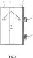
- Fig. 2 schematically depicts the operating principle on which the ultrasound transducer elements 21, 21' are based.
- Blood flows with a velocity V(b) through a blood vessel 3, e.g. a vein, of the limb 1.
- This blood flow velocity V(b) has a tangential component V(t) and a radial component V(r).
- the radial component V(r) may be detected using the transducer elements 21, 21' in or on the compression sleeve 15 surrounding the limb 1 using Doppler ultrasound measurements under control of the controller 30.
- the operation of the ultrasound transducers 21, 21' in an annular array 20, 20' by the controller 30 will now be explained in further detail with the aid of Fig. 3 , which depicts a flowchart of an example embodiment of an operating method 100 implemented by the controller 30.
- the operating method 100 starts in operation 101, e.g. by powering up the controller 30, after which the operating method 100 proceeds to a first mode of operation 103 in which for each annular array 20, 20' the ultrasound transducer elements 21, 21' are divided into two groups or subsets; a first subset containing the ultrasound transducer elements 21, 21' that will operate as ultrasound transmitters and a second subset containing the ultrasound transducer elements 21, 21' that will operate as ultrasound receivers.
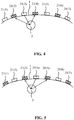
- Fig. 4 in which the ultrasound transducers 21(1), 21(3), 21(5) and 21(7) belong to the first subset, i.e. are operated as ultrasound transmitters and the ultrasound transducers 21(2), 21(4) and 21(6) belong to the second subset, i.e.
- each ultrasound transducer element 21(1), 21(3), 21(5), 21(7) in the first subset is located in between a pair of ultrasound transducer elements 21(2), 21(4), 21(6) in the second subset, or alternatively, each ultrasound transmitter has at least one and preferably two ultrasound receivers as its immediate neighbors in the annular array 20 (or 20').
- each ultrasound transmitter has at least one and preferably two ultrasound receivers as its immediate neighbors in the annular array 20 (or 20').
- other suitable geometries of the first and second subsets may be equally contemplated.
- the controller 30 operates the first subset of ultrasound transducer elements, i.e. the ultrasound transmitters in a continuous wave Doppler mode.
- the ultrasound transmitters continuously send out pulses of ultrasound, whilst the ultrasound receivers continuously listen for the multitude of reflected frequency shifts that are reflected back by the blood flow.
- Continuous wave Doppler facilitates the detection of the magnitude of blood flows, without being able to detect the actual location of the blood flow, i.e. the blood vessel 3, within the limb 1.
- ultrasound transducer elements 21(2), 21(4) and 21(6) will receive such frequency-shifted echoes, or at least receive such frequency-shifted echoes of a certain amplitude, because not all of the ultrasound transmitters, i.e. ultrasound transducer elements 21(1), 21(3), 21(5) and 21(7) will be within acoustic range of such a blood vessel 3.
- This aspect is leveraged in operation 105 in which the controller 30 evaluates which of the ultrasound receivers have received the strongest frequency-shifted echoes.
- This is symbolically indicated in Fig. 4 by the dashed arrows incident on ultrasound transducer elements 21(2) and 21(4), which represent the frequency-shifted echoes of the ultrasound pulses generated by the ultrasound transmitter, i.e. ultrasound transducer element 21(3) as indicated by the solid arrow.
- the controller 30 identifies the ultrasound receivers having received the strongest frequency-shifted echoes, and identifies the ultrasound transmitter responsible for the continuous wave Doppler pulses causing these frequency-shifted echoes from the spatial relationship between the ultrasound transmitters and the ultrasound receivers in the annular array 20 in the first mode of operation, here ultrasound transducer element 21(3) operating as an ultrasound transmitter, with the neighboring ultrasound transducer elements 21(2) and 21(4) acting as ultrasound receivers receiving the frequency-shifted echoes.
- the controller 30 therefore detects those ultrasound transducer elements 21, 21' that are capable of detecting a blood flow through the limb 1 of the wearer of the wearable article 10.
- the controller 30 may check in operation 107 if the first mode of operation needs to be repeated with a different compilation of the first and second subsets. This for example may be required where the spacing d between ultrasound transducer elements 21, 21' in the one or more annular arrays 20, 20' is large enough such that it cannot be ensured that an optimally positioned ultrasound transducer element relative to the blood vessel 3 can be found in a single cycle of the first mode of operation, e.g. a single cycle of the CW Doppler mode. If this is the case, it may be decided in operation 107 to revert back to operation 103 in which the first mode of operation of the wearable article 10 is repeated.
- the roles of the ultrasound transmitters and ultrasound receivers may be interchanged as schematically depicted in Fig. 5 such that the first subset of ultrasound transducer elements acting as ultrasound transmitters now comprises the ultrasound transducer elements 21(2), 21(4) and 21(6), whereas the second subset of ultrasound transducer elements acting as ultrasound receivers now comprises the ultrasound transducer elements 21(1), 21(3), 21(5) and 21(7).
- one or more ultrasound transducer elements acting as ultrasound transmitters may be identified by the controller 30 as being in acoustic range of the blood vessel 3 within the limb 1 based on the frequency-shifted echoes received by the ultrasound receivers in close vicinity to such an ultrasound transmitter, here ultrasound transducer element 21(4).
- the controller may then select the ultrasound transmitter having caused the strongest frequency-shifted echoes from the multiple cycles of the first mode of operation in operation 109 to identify the ultrasound transducer element of a particular annular array to be used for the monitoring of the blood flow velocity through a vein within the limb 1.
- the operating method 100 proceeds to operation 111 in which the one or more ultrasound transducer elements identified in operation 109 are operated to monitor the blood flow velocity through a vein in the limb 1, preferably using pulse wave Doppler ultrasound.
- the identified ultrasound transducer element(s) sends out a pulsed signal to a depth defined by the controller 30 in a transmission mode and then switches to a silent mode or a reception mode in operation 113 for a defined period of time in which the ultrasound transducer elements listens for the reflected frequency-shifted echo from that particular depth.
- the frequency shift scales with the velocity of the blood flow at that particular depth such that the controller 30 (or an external processor as previously explained) can calculate the blood flow velocity at that particular depth in operation 115.
- the controller 30 may systematically vary the depth within the limb 1 to which the pulsed signal by the identified ultrasound transducer element(s) in order to accurately locate the vein within the limb 1, in which case the operating method 100 returns to operation 111 to perform another pulse wave Doppler cycle in which the pulse penetration depth has been altered, and in a delay between the transmission event and the subsequent reception event is altered accordingly. This process may be repeated until the controller 30 has accurately determined the location of the vein within the limb 1.
- the controller 30 may decide in operation 117 to revert back to operation 111 in which another of the ultrasound transducer elements identified in a first mode of operation is selected to perform the pulse wave Doppler ultrasound.
- such a vein may be detected by scanning for locations within the limb 1 in a first sub mode that are characterized by blood flow directed away from the heart, e.g. blood flow through a central artery, after which in a second sub mode a region proximal to the identified blood flow is evaluated to detect a blood flow towards the heart, i.e. blood flow through a vein.
- This for example may be achieved using pulse wave Doppler ultrasound, in which such an adjacent region is systematically scanned using the originally identified ultrasound transducer element, e.g. by systematically altering the beam angle of this ultrasound transducer element to scan the adjacent region, or by selecting an ultrasound transducer element neighboring the originally identified ultrasound transducer element to scan such an adjacent region.
- the location of such a centrally located vein can be accurately determined and the blood flow velocity through this vein monitored as explained above.
- the operating method 100 may terminate in operation 119.
- the wearable article 10 comprises a plurality of annular arrays including a first annular array 20 of ultrasound transducer elements 21 and a second annular array 20' of ultrasound transducer elements 21' spatially separated from the first annular array 20, wherein each ultrasound transducer element 21,21' comprises a single ultrasound transducer only.
- blood flow direction may be detected by operating all ultrasound transducer elements 21 of the first annular array 20 in a transmission mode and all ultrasound transducer elements 21' of the second annular array 20' in a reception mode. Because the signal path of the ultrasound signals is parallel to the blood flow, one could also determine flow direction in this setup.
- the controller 30 or the external device 40 may use the monitored blood flow velocity of a monitored vein to generate an alarm when the monitored blood flow velocity falls below a defined threshold or is continually decreasing.
- an alarm may be intended to trigger the wearer of the wearable article 10 to perform exercises to stimulate blood circulation through the limb 1 or to alert another person, e.g. a medical professional such as a nurse, to attend to the wearer of the wearable article 10 in order to alert the wearer to the need for performing such exercises or alternatively massage the limb of the wearer in case the wearer is physically incapable of performing such exercises, as may be the case with bed-ridden patients.
- the blood flow velocity monitoring data may be visualized on the output device such as the output device 35 or the external output device 41 such that the wearer of the wearable article 10 or anybody else monitoring this data can keep track of the blood flow velocity through the monitored vein over time.
- the one or more annular arrays 20, 20' of ultrasound transducer elements 21, 21' may be arranged to acquire an ultrasound image of the target region within the limb 1, i.e. the region including the vein being monitored.
- Such an ultrasound image for example may be a B-mode ultrasound image.
- the image data may be evaluated together with the blood flow velocity monitoring data, e.g. to identify the veins having no blood flow adjacent to arteries having a high blood flow, such that problematic veins can be visualized in this manner.
- the parameters used for the acquisition of such an ultrasound image may be based on the depth information extracted from the aforementioned pulse wave Doppler ultrasound mode in order to optimize the resolution of the target region of interest captured in such an ultrasound image.
Landscapes
- Health & Medical Sciences (AREA)
- Life Sciences & Earth Sciences (AREA)
- Animal Behavior & Ethology (AREA)
- Veterinary Medicine (AREA)
- Public Health (AREA)
- General Health & Medical Sciences (AREA)
- Biophysics (AREA)
- Medical Informatics (AREA)
- Surgery (AREA)
- Molecular Biology (AREA)
- Heart & Thoracic Surgery (AREA)
- Physics & Mathematics (AREA)
- Biomedical Technology (AREA)
- Engineering & Computer Science (AREA)
- Pathology (AREA)
- Radiology & Medical Imaging (AREA)
- Nuclear Medicine, Radiotherapy & Molecular Imaging (AREA)
- Hematology (AREA)
- Epidemiology (AREA)
- Gynecology & Obstetrics (AREA)
- Rehabilitation Therapy (AREA)
- Pain & Pain Management (AREA)
- Physical Education & Sports Medicine (AREA)
- Cardiology (AREA)
- Physiology (AREA)
- Ultra Sonic Daignosis Equipment (AREA)
Priority Applications (1)
| Application Number | Priority Date | Filing Date | Title |
|---|---|---|---|
| EP17205388.6A EP3494894A1 (de) | 2017-12-05 | 2017-12-05 | Intelligente kompressionsmanschette |
Applications Claiming Priority (1)
| Application Number | Priority Date | Filing Date | Title |
|---|---|---|---|
| EP17205388.6A EP3494894A1 (de) | 2017-12-05 | 2017-12-05 | Intelligente kompressionsmanschette |
Publications (1)
| Publication Number | Publication Date |
|---|---|
| EP3494894A1 true EP3494894A1 (de) | 2019-06-12 |
Family
ID=60654677
Family Applications (1)
| Application Number | Title | Priority Date | Filing Date |
|---|---|---|---|
| EP17205388.6A Withdrawn EP3494894A1 (de) | 2017-12-05 | 2017-12-05 | Intelligente kompressionsmanschette |
Country Status (1)
| Country | Link |
|---|---|
| EP (1) | EP3494894A1 (de) |
Cited By (3)
| Publication number | Priority date | Publication date | Assignee | Title |
|---|---|---|---|---|
| CN115474911A (zh) * | 2022-10-26 | 2022-12-16 | 首都医科大学宣武医院 | 一种足部血运状态监测系统 |
| US11839350B2 (en) * | 2018-05-03 | 2023-12-12 | Monovo, LLC | Ultrasound transducer system for wearable monitoring device |
| WO2024119150A1 (en) * | 2022-12-02 | 2024-06-06 | Invensense, Inc. | Transversal ultrasonic sensing for cardiovascular monitoring |
Citations (5)
| Publication number | Priority date | Publication date | Assignee | Title |
|---|---|---|---|---|
| US3552382A (en) * | 1968-01-11 | 1971-01-05 | Hoffmann La Roche | Ultrasonic transducer assembly for biological inspections |
| US5843007A (en) | 1996-04-29 | 1998-12-01 | Mcewen; James Allen | Apparatus and method for periodically applying a pressure waveform to a limb |
| US20070225606A1 (en) * | 2006-03-22 | 2007-09-27 | Endothelix, Inc. | Method and apparatus for comprehensive assessment of vascular health |
| US20090003675A1 (en) * | 2007-03-27 | 2009-01-01 | Siemens Corporate Research, Inc. | Bleeding Detection Using a Blanket Ultrasound Device |
| US20110295129A1 (en) * | 2008-11-28 | 2011-12-01 | Royal United Hosptial Bath NHS Trust | Method of measuring blood pressure and apparatus for performing the same |
-
2017
- 2017-12-05 EP EP17205388.6A patent/EP3494894A1/de not_active Withdrawn
Patent Citations (5)
| Publication number | Priority date | Publication date | Assignee | Title |
|---|---|---|---|---|
| US3552382A (en) * | 1968-01-11 | 1971-01-05 | Hoffmann La Roche | Ultrasonic transducer assembly for biological inspections |
| US5843007A (en) | 1996-04-29 | 1998-12-01 | Mcewen; James Allen | Apparatus and method for periodically applying a pressure waveform to a limb |
| US20070225606A1 (en) * | 2006-03-22 | 2007-09-27 | Endothelix, Inc. | Method and apparatus for comprehensive assessment of vascular health |
| US20090003675A1 (en) * | 2007-03-27 | 2009-01-01 | Siemens Corporate Research, Inc. | Bleeding Detection Using a Blanket Ultrasound Device |
| US20110295129A1 (en) * | 2008-11-28 | 2011-12-01 | Royal United Hosptial Bath NHS Trust | Method of measuring blood pressure and apparatus for performing the same |
Cited By (4)
| Publication number | Priority date | Publication date | Assignee | Title |
|---|---|---|---|---|
| US11839350B2 (en) * | 2018-05-03 | 2023-12-12 | Monovo, LLC | Ultrasound transducer system for wearable monitoring device |
| CN115474911A (zh) * | 2022-10-26 | 2022-12-16 | 首都医科大学宣武医院 | 一种足部血运状态监测系统 |
| CN115474911B (zh) * | 2022-10-26 | 2024-05-28 | 首都医科大学宣武医院 | 一种足部血运状态监测系统 |
| WO2024119150A1 (en) * | 2022-12-02 | 2024-06-06 | Invensense, Inc. | Transversal ultrasonic sensing for cardiovascular monitoring |
Similar Documents
| Publication | Publication Date | Title |
|---|---|---|
| US20200163644A1 (en) | Fetal heart rate monitoring system | |
| JP5837744B2 (ja) | 心拍数モニタと共に用いられる超音波プローブ | |
| EP3349661B1 (de) | Vorrichtung und verfahren zur bestimmung der fötalen herzfrequenz | |
| US11382598B2 (en) | Device and method for determining fetal heart rate | |
| CA3050694C (en) | Non-invasive blood pressure measurement using pulse wave velocity | |
| IL209212A (en) | A patient's heart monitoring device | |
| JP2006271896A (ja) | 脈波検出装置及びその方法 | |
| EP3494894A1 (de) | Intelligente kompressionsmanschette | |
| US8221337B2 (en) | System and method for monitoring bladder distention in a variety of patients having differing anatomical proportions | |
| EP3720359B1 (de) | Patientenüberwachung | |
| CN111568468B (zh) | 超声波芯片、超声波检测装置及检测血压的方法 | |
| US20150243190A1 (en) | Blood pressure measurement apparatus | |
| EP4108165B1 (de) | Vorrichtung und verfahren zur schätzung von bioinformationen | |
| JP2008237533A (ja) | 脈波測定装置 | |
| JP2019058573A (ja) | 生体信号取得装置、および生体信号取得用装着具 | |
| US12279914B2 (en) | Internal bleeding detection, assessment and monitoring devices, systems and methods | |
| JP7138244B2 (ja) | 血圧測定装置、血圧測定システム、血圧測定方法、及び、血圧測定プログラム | |
| JP2010207344A (ja) | 血流圧力血流速度状態判定装置およびその判定方法 | |
| CN109414248A (zh) | 脂肪层相关传感器调整 | |
| JP2015228159A (ja) | 非接触見守り生体センシング装置 | |
| KR101038425B1 (ko) | 환자의 움직임이 감지되는 혈압 변화 측정장치 | |
| JP2007075482A (ja) | 脈拍数測定装置 | |
| CN115211823A (zh) | 血压测量装置及方法 | |
| WO2006005351A1 (en) | Handheld ultrasound vessels imager facilitating intravascular injection |
Legal Events
| Date | Code | Title | Description |
|---|---|---|---|
| PUAI | Public reference made under article 153(3) epc to a published international application that has entered the european phase |
Free format text: ORIGINAL CODE: 0009012 |
|
| AK | Designated contracting states |
Kind code of ref document: A1 Designated state(s): AL AT BE BG CH CY CZ DE DK EE ES FI FR GB GR HR HU IE IS IT LI LT LU LV MC MK MT NL NO PL PT RO RS SE SI SK SM TR |
|
| AX | Request for extension of the european patent |
Extension state: BA ME |
|
| RAP1 | Party data changed (applicant data changed or rights of an application transferred) |
Owner name: KONINKLIJKE PHILIPS N.V. |
|
| STAA | Information on the status of an ep patent application or granted ep patent |
Free format text: STATUS: THE APPLICATION IS DEEMED TO BE WITHDRAWN |
|
| 18D | Application deemed to be withdrawn |
Effective date: 20191213 |