EP3495579A1 - Reinraumsystem für hochreinräume - Google Patents
Reinraumsystem für hochreinräume Download PDFInfo
- Publication number
- EP3495579A1 EP3495579A1 EP18210114.7A EP18210114A EP3495579A1 EP 3495579 A1 EP3495579 A1 EP 3495579A1 EP 18210114 A EP18210114 A EP 18210114A EP 3495579 A1 EP3495579 A1 EP 3495579A1
- Authority
- EP
- European Patent Office
- Prior art keywords
- wall elements
- clean room
- room system
- shaped
- elements
- Prior art date
- Legal status (The legal status is an assumption and is not a legal conclusion. Google has not performed a legal analysis and makes no representation as to the accuracy of the status listed.)
- Granted
Links
Images


Classifications
-
- E—FIXED CONSTRUCTIONS
- E04—BUILDING
- E04B—GENERAL BUILDING CONSTRUCTIONS; WALLS, e.g. PARTITIONS; ROOFS; FLOORS; CEILINGS; INSULATION OR OTHER PROTECTION OF BUILDINGS
- E04B2/00—Walls, e.g. partitions, for buildings; Wall construction with regard to insulation; Connections specially adapted to walls
- E04B2/74—Removable non-load-bearing partitions; Partitions with a free upper edge
- E04B2/82—Removable non-load-bearing partitions; Partitions with a free upper edge characterised by the manner in which edges are connected to the building; Means therefor; Special details of easily-removable partitions as far as related to the connection with other parts of the building
-
- E—FIXED CONSTRUCTIONS
- E04—BUILDING
- E04B—GENERAL BUILDING CONSTRUCTIONS; WALLS, e.g. PARTITIONS; ROOFS; FLOORS; CEILINGS; INSULATION OR OTHER PROTECTION OF BUILDINGS
- E04B2/00—Walls, e.g. partitions, for buildings; Wall construction with regard to insulation; Connections specially adapted to walls
- E04B2/74—Removable non-load-bearing partitions; Partitions with a free upper edge
- E04B2/7401—Removable non-load-bearing partitions; Partitions with a free upper edge assembled using panels without a frame or supporting posts, with or without upper or lower edge locating rails
-
- E—FIXED CONSTRUCTIONS
- E04—BUILDING
- E04B—GENERAL BUILDING CONSTRUCTIONS; WALLS, e.g. PARTITIONS; ROOFS; FLOORS; CEILINGS; INSULATION OR OTHER PROTECTION OF BUILDINGS
- E04B2/00—Walls, e.g. partitions, for buildings; Wall construction with regard to insulation; Connections specially adapted to walls
- E04B2/74—Removable non-load-bearing partitions; Partitions with a free upper edge
- E04B2/7407—Removable non-load-bearing partitions; Partitions with a free upper edge assembled using frames with infill panels or coverings only; made-up of panels and a support structure incorporating posts
- E04B2/7453—Removable non-load-bearing partitions; Partitions with a free upper edge assembled using frames with infill panels or coverings only; made-up of panels and a support structure incorporating posts with panels and support posts, extending from floor to ceiling
- E04B2/7455—Glazing details
-
- E—FIXED CONSTRUCTIONS
- E04—BUILDING
- E04B—GENERAL BUILDING CONSTRUCTIONS; WALLS, e.g. PARTITIONS; ROOFS; FLOORS; CEILINGS; INSULATION OR OTHER PROTECTION OF BUILDINGS
- E04B2/00—Walls, e.g. partitions, for buildings; Wall construction with regard to insulation; Connections specially adapted to walls
- E04B2/74—Removable non-load-bearing partitions; Partitions with a free upper edge
- E04B2002/749—Partitions with screw-type jacks
- E04B2002/7492—Partitions with screw-type jacks used in partitions extending from floor to ceiling
-
- E—FIXED CONSTRUCTIONS
- E04—BUILDING
- E04B—GENERAL BUILDING CONSTRUCTIONS; WALLS, e.g. PARTITIONS; ROOFS; FLOORS; CEILINGS; INSULATION OR OTHER PROTECTION OF BUILDINGS
- E04B2/00—Walls, e.g. partitions, for buildings; Wall construction with regard to insulation; Connections specially adapted to walls
- E04B2/74—Removable non-load-bearing partitions; Partitions with a free upper edge
- E04B2002/7498—Partitions for clean rooms
Definitions
- the invention relates to a clean room system for high clean rooms, which has wall elements, floor mounting elements with at least one mounting rail and U-shaped ceiling mounting elements. Furthermore, a development for glass elements is proposed.
- each product is manufactured in a separate such clean room, which must be free of dust and germs.
- the factory space must, as it were, be subdivided into many smaller clean rooms, so that separate clean rooms, each usable for the production of a product, result.
- This construction of the separated clean rooms is done by arranging wall elements on the building walls and / or building ceilings and / or building floors and by arranging functional elements, such as doors to enter the clean rooms or supply shafts in these wall elements.
- glass elements can be used by which an operator can monitor, for example, a working in the interior of a clean room machine without having to enter the clean room.
- such glass walls also have a particularly advantageous effect on the lighting of the clean rooms.
- the clean room system comprises wall elements and fastening elements for fastening these wall elements to building floors and building ceilings.
- the wall elements At least on their side facing the bottom, the wall elements have a groove which in particular runs parallel to the front of the wall elements. Preferably, the groove extends over the entire width of the wall elements.
- the wall elements additionally have a groove on the opposite side. This makes it possible to mount the wall elements in two different orientations.
- the wall elements consist for example of metal, in particular of a light metal such. As aluminum, or plastic.
- the bottom attachment element is preferably at least partially made of metal, in particular of a light metal such. As aluminum.
- the floor fastening element has at least one fastening rail, to which the bottom groove of the wall elements is adapted. More specifically, the shape and depth of the groove are adapted to the shape and height of the mounting rail. The shape also includes a width of the groove or the mounting rail and an angle in which the two are formed in comparison to the bottom side or to the bottom fastening element.
- the fastening rail preferably also consists of metal, in particular of the same material as the fastening element, and is advantageously formed integrally with the floor fastening element.
- a U-shaped ceiling fastening element is provided for fastening the wall elements to a building ceiling.
- "U-shaped" means that the element has two legs that protrude substantially at right angles from a common base in the same direction.
- the ceiling fixing element is preferably at least partially made of metal, in particular of a light metal such. As aluminum.
- the U-shaped ceiling fastener is attached to its base attached to the building corner. For attachment, any type of fasteners that provide enough grip, z. As screws used.
- the U-shaped ceiling fastening element is designed such that the wall elements between the legs of the U-shaped ceiling fastening element can be inserted.
- the distance between the base of the ceiling fastening element and the edge or side of the wall elements pointing in the direction of the ceiling is the same or greater than the height of the fastening rail.
- This structure is particularly well suited for mounting the wall elements.
- the wall elements can be inserted in a simple manner first in the ceiling mounting element. When the upper edge of the wall elements abuts against the base of the ceiling mounting element, the wall elements can be displaced, tilted and / or moved such that the groove is positioned freely over the mounting rail.
- the wall elements Since the distance between the base of the ceiling-mounting member and the facing in the ceiling edge or side of the wall elements is equal to or greater than the height of the mounting rail, the wall elements, when they were fully retracted into the ceiling mounting element, not to the mounting rail of Floor fastener on.
- the mounting of the wall elements is significantly simplified. Subsequently, the wall element is drained and the mounting rail engages in the groove of the wall elements.
- the legs of the U-shaped ceiling fastening element are formed so that they on the one hand allow insertion of the wall elements and on the other hand enclose the wall elements in the retracted state.
- the floor fastening element has two fastening rails, which are arranged at a horizontal distance from each other.
- the two fastening rails run essentially parallel to one another.
- a wall element can be inserted into each of the two fastening rails, so that they are spaced apart by the horizontal distance.
- the ceiling mounting element can be adjusted by two U-shaped ceiling mounting elements are arranged side by side with the horizontal distance of the wall elements or a common element is provided, which has two U-shaped ceiling mounting elements.
- the bottom attachment element preferably has a U-shaped bottom part and a U-shaped end part.
- the U-shaped bottom part is arranged with its base on the building floor so that its legs point away from the ground.
- the termination part has the attachment rail or attachment rails at its base in the opposite direction to its legs.
- the end part can be plugged onto the bottom part, the legs of the end part preferably embracing or being encompassed by the legs of the bottom part. It can be provided that, when the legs of the closure part embrace the legs of the bottom part, the distance of the inner edges of the legs of the closure part is slightly smaller than the distance of the outer edges of the legs of the bottom part. Thus, when plugging a mechanical tension between the legs is obtained.
- the U-shaped end part may have a plate which forms the base completely or at least partially. It is in other words a plate inserted into the base of the final part.
- the plate is releasably connected to the legs of the closure part.
- the width of the plate is adapted to the width of the wall elements and the distance between the wall elements. If the floor fastening elements have two fastening rails as described above, the two fastening rails on the closing part are separated from one another by the plate. Thereby, the horizontal distance between the wall elements and thus also the space available as a space can be varied.
- the bottom attachment element has an adjustment element, which is arranged between the bottom part and the termination part.
- the adjusting element on a base body and a turntable, which are connected together by a screw.
- the main body is arranged on the base part and the turntable is in contact with the end part.
- the turntable may preferably only be in contact with the plate of the closure part.
- the adjusting element is adapted to move the end part and the bottom part against each other and thus to change the vertical distance between the end part and the bottom, whereby the wall elements are adjustable in height.
- the floor attachment member has a groove disposed on the outside thereof where the wall members rest on the floor attachment member.
- This is for example in the case of a floor fastening element with a closure part described above on the outer edge of the upper side of the closure part.
- sealing material such. As silicone, be inserted to hermetically seal the connection between the bottom attachment element and the wall element.
- the bottom attachment element in particular the termination part, has at least one recess for a corner connector, which connects the bottom attachment elements to one another across a corner.
- the corner connector is inserted into a recess of one of the floor fasteners and fastened there. Then another floor fixing element is pushed with its recess on the corner connector and then attached.
- the wall elements comprise honeycomb reinforced struts, ie, the struts are reinforced with a honeycomb structure.
- the honeycomb-reinforced struts are preferably arranged in vertical strips preferably on the back of the wall elements.
- the reinforced with honeycomb braces are used to structural elements To give stability. In particular with regard to horizontally acting (shear) forces, the honeycomb-shaped structure offers increased stability, which counteracts a curvature of the wall elements. The extra stability is particularly with floor-to-ceiling wall elements - these are typically up to 4 m high - of particular effect.
- the clean room system additionally comprises stands which can be inserted into the floor fastening elements and into the ceiling fastening elements.
- the stands form a conclusion for the wall elements and serve to functional elements, such. As doors or windows, and thus to implement in the clean room.
- the stands also have a bottom groove. This groove corresponds to the groove of the wall elements described above and is also adapted to the mounting rail.
- the stands are fastened analogously to the wall elements in the ceiling fastening elements and by the fastening rail.
- windows can also be provided, which are realized by glass elements.
- a single glass element can cover the entire room height, or a combination can be provided between at least one smaller wall element and a glass element.
- For mounting the glass elements can advantageously be provided for both cases C-shaped profiles.
- the C-shaped profiles are glued at their base with the glass elements.
- the C-shaped profiles run around the glass elements on all sides and are, for example, riveted together.
- double-glazed windows are preferred.
- two C-shaped profiles are interconnected by a common leg.
- the two C-shaped profiles share a common leg, which combines the two C-shaped profiles into one profile.
- Each of the two bases of the two C-shaped profiles is glued to a separate glass element. This creates a double glazing.
- the length of the common leg of the two C-shaped profiles corresponds to the horizontal distance of the wall elements, so that the wall elements and the glass elements are aligned.
- one of the legs of the C-shaped profile is formed so that it rests on the floor fixing element and at the same time bears against the fastening rail.
- two C-shaped profiles are connected to each other by a common leg, to note that the leg which can be placed on the floor-fixing element is not the common leg in this case.
- the C-shaped profile can be placed on the wall elements by means of a holding device.
- the holding device is then attached to the supports already described and engages in the groove of the wall elements.
- the holding device comprises a U-shaped connecting piece, the leg of which engages in the groove of the wall elements and on whose legs the C-shaped profile is applied, and connected to the base of the connecting piece mounting plate, which is connected with conventional fastening means, for. B. screws, is attached to the uprights.
- conventional fastening means for. B. screws
- spacers which space the C-shaped profile from a base, in the case described above, from the holding device. These spacers can, for. B. screws.
- the clean room system further functional elements, such. As doors or the like., Have.
- the functional elements are attached to the stands already described.
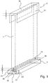
- FIG. 1 shows an isometric view of a first embodiment of the clean room system according to the invention for high purity.
- the clean room system has wall elements 1 which, on their side facing the floor, have a groove 10 which runs parallel to the front of the wall elements 1 over the entire width of the wall elements 1.
- a floor fixing element 2 for fixing the wall element 1 to a building floor, not shown.
- the floor fastening element 2 has a U-shaped bottom part 21 and a U-shaped end part 22, which are inserted into one another. According to the invention is integrally connected to the end part 22 Mounting rail 20 is provided.
- the height H, the width and the angle, ie the shape of the fastening rail 20 correspond essentially to the depth, the width and the angle, ie the shape of the groove 10 of the wall elements 1.
- the construction of the floor fastening element 1 is in FIG. 2 clarifies.
- a U-shaped ceiling fastening element 3 is provided for fastening the wall element 1 to a building ceiling, not shown.
- the construction of the ceiling fixing element 3 is in FIG. 3 clarifies.
- the U-shaped ceiling fastening element 3 is designed such that the wall element 1 between legs 31 of the U-shaped ceiling fastening element 3 can be inserted.
- the distance A between a base 30 of the ceiling-mounting member 3 and a ceiling-side, upper edge of the wall element 1 is greater than the height H of the mounting rail 20 is.
- the wall elements 1 are first inserted into the ceiling fixing element 3.
- the wall elements 1 can be displaced, tilted and / or moved such that the groove 10 is positioned freely above the fastening rail 20. Subsequently, the wall element 1 is drained and the mounting rail 20 engages in the groove 10 a.
- the legs 31 of the U-shaped ceiling fastening element are formed so that they allow on the one hand insertion of the wall elements 1 and on the other hand, in an inserted state, the wall elements 1 enclose.
- An adjusting element 4 is arranged between the bottom part 21 and the end part 22.
- the adjusting element 4 has a main body 41 and a turntable 42, which are connected to one another via a screw 43.
- the main body 41 stands on the bottom part 21 and the end part 22 rests on the turntable 42.
- the adjusting element 4 is adapted to move the end portion 22 and the bottom portion 21 against each other and thus to change the vertical distance between the end portion 22 and the bottom.
- the wall elements 1 are adjustable in height.
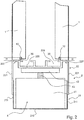
- FIG. 2 shows a schematic representation of a bottom fastening element 2 with two fastening rails 20, which are arranged at a horizontal distance from each other and extend substantially parallel to each other.
- a wall element 1 is by means of its groove 10 at each of the two Attachment rails 20 arranged so that they are spaced apart by the horizontal distance.
- the bottom attachment element has a U-shaped bottom part 21 with a base 210 and two legs 211 and a U-shaped end part 22 likewise with a base 220 and two legs 221.
- the U-shaped bottom part 21 is fixed with its base 210 on the building floor so that its legs 211 point away from the ground.
- the end piece 22 has the fastening rails 20 at its base 220 in the opposite direction to its legs 221.
- the end part 22 is attached to the bottom part 21, wherein the legs 221 of the end part 22 surround the legs 211 of the bottom part 21 and the distance between the inner edges of the legs 221 of the end part 22 is slightly smaller than the distance of the outer edges of the legs 211 of the bottom part 21.
- the termination member 22 may include a plate, not shown here, as a base 220 between the two attachment rails 20 releasably connected to the legs 221.
- the width of the plate is adapted to the width of the wall elements 1 to the distance between the wall elements 1.
- the end part 22 has two grooves 227 at the connection point to the wall elements 1, which is accessible from the outside. In this groove silicone can be inserted for sealing.
- the end element 22 in this embodiment has two recesses 225 for corner connectors, not shown, with which the floor fastening elements 1 can be connected to each other across a corner away.
- FIG. 3 shows a schematic representation of two ceiling mounting elements 3, which are connected to each other via a common web 32.
- a wall element 1 is inserted in this figure.
- the distance A of the ceiling-side edge of the wall elements 1 to the base 30 of the ceiling mounting elements 3 in the inserted state is greater than the height H of the mounting rail 20.
- the length of the web 3 is adapted to the distance between the two wall elements 1 and also to the horizontal distance between the two mounting rails 20 of the floor fastening element 2 FIG. 2 customized.
- the wall elements 1 here also have a groove 11 on the ceiling side.
- the ceiling fixing element is fastened by means of screws 35 to the building ceiling.
- FIG. 4 shows a schematic representation of the wall element 1.
- the wall element 1 has arranged in strips honeycomb-reinforced struts 15, which are made of aluminum, through which the structural stability is increased.
- the two grooves 10 and 11 are indicated. Due to the symmetrical design of the wall elements 1, these can be mounted in the orientation shown and in a rotated by 180 ° orientation.
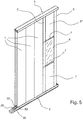
- FIG. 5 shows a schematic representation of the clean room system, in which in addition to the wall elements 1 and glass elements 6 are provided.
- the wall elements 1 are closed by stand 5.
- the stands 5 serve to integrate functional elements, such as the window or doors, not shown, in the clean room system and are used in the connection points between the wall elements 1 and the functional elements.
- the uprights 5 likewise have a groove 50, which essentially corresponds to the groove 10 of the wall elements 1.
- the mounting rail 20 engages the groove 50 of the uprights 5 to secure the uprights 5.
- the uprights 5 are likewise fastened by means of the ceiling fastening element 3.
- the wall elements indicated by the reference numerals 1 'and 1 "are smaller wall elements which are constructed the same as the wall-to-ceiling wall elements 1.
- the relationship between glass elements 6 and the C-shaped profiles 7 will be described in relation to FIGS FIGS. 6 to 8 explained.
- FIG. 6 shows the connection of floor to ceiling glass elements 6 and the FIGS. 7 and 8th show the arrangement of the glass elements 6 at falls.
- C-shaped profiles 7 are provided for both cases.
- the C-shaped profiles 7 are glued at their base 70 with the glass elements 6.
- the C-shaped profiles 7 run around the glass elements 6 on all sides and are riveted together.
- the C-shaped profiles 7 shown here are connected to each other by a common leg 71 to form a profile.
- Each of the two bases 70 of the two C-shaped profiles 7 is glued to a separate glass element 6.
- the length of the common Leg 71 of the two C-shaped profiles 7 corresponds to the horizontal distance of the wall elements. 6
- FIG. 6 is shown, as in each of the two C-shaped profiles 7, the other leg 72 on the closing element 22 of the floor fixing element 2 from FIG. 2 rests and simultaneously rests on one of the two mounting rails 20. Since the leg 72 of the two C-shaped profiles 7 abuts against the respective fastening rail 20 from opposite sides, the C-shaped profiles 7 and thus the glass elements 6 are secured.
- FIG. 7 and 8th It is shown how the C-shaped profile by means of a holding device 8 with the wall elements 1 'and 1 "are connected.
- FIG. 7 shows the connection towards the ground and FIG. 8 the connection towards the ceiling. Since the two connections are substantially the same, both will be described together below.
- the holding device 8 is fastened via a mounting plate 85 by means of screws to the uprights 5.
- the holding device 8 comprises a U-shaped connecting piece 80, the base 800 is connected to the mounting plate 85 and the legs 801 in the groove 10 and 11 of the wall elements 1 'rang.1 "engages and on the legs 801 of the C-shaped
- spacers 75 are provided between the common leg 71 of the C-shaped profiles 7 and the connecting piece 80. The spacers form a respective groove 727 between the wall elements 1 and the glass elements 6, into which silicone is inserted Spacers 75 are screws.
Landscapes
- Engineering & Computer Science (AREA)
- Architecture (AREA)
- Physics & Mathematics (AREA)
- Electromagnetism (AREA)
- Civil Engineering (AREA)
- Structural Engineering (AREA)
- Ventilation (AREA)
Abstract
Description
- Die Erfindung betrifft ein Reinraumsystem für Hochreinräume, welches Wandelemente, Bodenbefestigungselemente mit zumindest einer Befestigungsschiene und U-förmige Deckenbefestigungselemente aufweist. Ferner wird eine Weiterbildung für Glaselemente vorgeschlagen.
- In einem Reinraum herrscht eine reine, staubfreie und gegebenenfalls keimfreie Atmosphäre. Hochreine Räume finden heutzutage mannigfaltige Anwendung, beispielsweise in der pharmazeutischen Industrie, in der Mikroelektronik, in der Feinwerkmechanik oder in der Optik.
- Oftmals ist bei der Herstellung unterschiedlicher Produkte, insbesondere bei Arzneimitteln, erforderlich, dass jedes Produkt in einem separaten derartigen Reinraum, der staub- und keimfrei sein muss, hergestellt wird. Um nun in einem größeren Fabrikraum mehrere unterschiedliche Produkte gleichzeitig herstellen zu können, muss der Fabrikraum gewissermaßen in viele kleinere Reinräume unterteilt werden, so dass sich voneinander separierte und jeweils für die Herstellung eines Produkts verwendbare Reinräume ergeben. Dieser Aufbau der voneinander separierten Reinräume geschieht durch Anordnen von Wandelementen an den Gebäudewänden und/oder Gebäudedecken und/oder Gebäudeböden und durch Anordnen von Funktionselementen, beispielsweise Türen zum Betreten der Reinräume oder auch Versorgungsschächten in diesen Wandelementen. Zudem können Glaselemente verwendet werden, durch welche eine Bedienungsperson beispielsweise eine in dem Inneren eines Reinraums arbeitende Maschine überwachen kann, ohne den Reinraum betreten zu müssen. Darüber hinaus wirken sich derartige Glaswände auch besonders vorteilhaft auf die Beleuchtung der Reinräume aus.
- Es wird ein Reinraumsystem für Hochreinräume vorgeschlagen. Das Reinraumsystem umfasst Wandelemente und Befestigungselemente zur Befestigung dieser Wandelemente an Gebäudeböden und Gebäudedecken. Die Wandelemente weisen zumindest an ihrer dem Boden zugewandten Seite eine Nut auf, die insbesondere parallel zur Front der Wandelemente verläuft. Vorzugsweise verläuft die Nut über die gesamte Breite der Wandelemente. Optional weisen die Wandelemente zusätzliche eine Nut an der gegenüberliegenden Seite auf. Dadurch ist es möglich die Wandelemente in zwei verschiedenen Orientierungen zu montieren. Die Wandelemente bestehen beispielsweise aus Metall, insbesondere aus einem Leichtmetall wie z. B. Aluminium, oder aus Kunststoff.
- Als Befestigungselemente sind einerseits Bodenbefestigungselemente zur Befestigung der Wandelemente an einem Gebäudeboden vorgesehen. Das Bodenbefestigungselement besteht vorzugsweise zumindest teilweise aus Metall, insbesondere aus einem Leichtmetall wie z. B. Aluminium. Das Bodenbefestigungselement weist zumindest eine Befestigungsschiene auf, an welche die bodenseitige Nut der Wandelemente angepasst ist. Genauer gesagt, sind die Form und die Tiefe der Nut an die Form und die Höhe der Befestigungsschiene angepasst. Zur Form gehört hierbei auch eine Breite der Nut bzw. der Befestigungsschiene und ein Winkel, in dem die beiden im Vergleich zur Bodenseite bzw. zum Bodenbefestigungselement ausgebildet sind. Die Befestigungsschiene besteht vorzugsweise ebenfalls aus Metall, insbesondere aus demselben Material wie das Befestigungselement, und ist vorteilhafterweise einteilig mit dem Bodenbefestigungselement ausgebildet.
- Zudem ist ein U-förmiges Deckenbefestigungselement zur Befestigung der Wandelemente an einer Gebäudedecke vorgesehen. In der weiteren Beschreibung bedeutet "U-förmig", dass das Element zwei Schenkel aufweist, die im Wesentlichen rechtwinklig aus einer gemeinsamen Basis in die gleiche Richtung hervorstehen. Das Deckenbefestigungselement besteht vorzugsweise zumindest teilweise aus Metall, insbesondere aus einem Leichtmetall wie z. B. Aluminium. Das U-förmige Deckenbefestigungselement ist mit seiner Basis an der Gebäudeecke befestigt. Zur Befestigung können jede Art von Befestigungsmittel, die genug Halt bieten, z. B. Schrauben, verwendet werden.
- Das U-förmige Deckenbefestigungselement ist derart ausgebildet, dass die Wandelemente zwischen die Schenkel des U-förmigen Deckenbefestigungselements einschiebbar sind. Erfindungsgemäß ist vorgesehen, dass der Abstand zwischen der Basis des Deckenbefestigungselements und der in Richtung der Decke zeigenden Kante bzw. Seite der Wandelemente gleich groß oder größer als die Höhe der Befestigungsschiene ist. Dieser Aufbau ist für die Montage der Wandelemente besonders gut geeignet. So lassen sich die Wandelemente in einfacher Weise zuerst in das Deckenbefestigungselement einschieben. Liegt die obere Kante der Wandelemente an der Basis des Deckenbefestigungselements an, können die Wandelemente so verschoben, gekippt und/oder bewegt werden, dass die Nut frei über der Befestigungsschiene positioniert ist. Da der Abstand zwischen der Basis des Deckenbefestigungselements und der in Richtung der Decke zeigenden Kante bzw. Seite der Wandelemente gleich groß oder größer als die Höhe der Befestigungsschiene ist, stoßen die Wandelemente, wenn sie ganz in das Deckenbefestigungselement eingefahren wurden, nicht an die Befestigungsschiene des Bodenbefestigungselements an. Durch diese vorteilhafte Kombination des aneinander angepassten Abstands zwischen der Basis des Deckenbefestigungselements und der deckenseitigen Kante der Wandelemente mit der Höhe der Befestigungsschiene wird demzufolge die Montage der Wandelemente deutlich vereinfacht. Anschließend wird das Wandelement abgelassen und die Befestigungsschiene greift in die Nut der Wandelemente ein. Die Schenkel des U-förmigen Deckenbefestigungselements sind so ausgebildet, dass sie einerseits ein Einschieben der Wandelemente ermöglichen und andererseits im eingeschobenen Zustand die Wandelemente umschließen.
- Gemäß einem Aspekt weist das Bodenbefestigungselement zwei Befestigungsschienen auf, die in einem horizontalen Abstand zueinander angeordnet sind. Vorzugsweise laufen die beiden Befestigungsschienen im Wesentlichen parallel zueinander. Jeweils ein Wandelement kann in jede der beiden Befestigungsschienen eingefügt werden, sodass diese um den horizontalen Abstand zueinander beabstandet sind. In den dadurch entstehenden Zwischenraum können Funktionskomponenten, Leitungen und Ähnliches, die zum Betrieb notwendig sind, verbaut werden. Entsprechend kann das Deckenbefestigungselement angepasst werden, indem zwei U-förmige Deckenbefestigungselemente nebeneinander mit dem horizontalen Abstand der Wandelemente angeordnet werden oder ein gemeinsames Element vorgesehen ist, welches zwei U-förmige Deckenbefestigungselemente aufweist.
- Das Bodenbefestigungselement weist vorzugsweise ein U-förmiges Bodenteil und ein U-förmiges Abschlussteil auf. Das U-förmige Bodenteil ist mit seiner Basis auf dem Gebäudeboden so angeordnet, dass dessen Schenkel vom Boden wegzeigen. Zur Befestigung des Bodenteils am Gebäudeboden können jede Art von Befestigungsmittel, die genug Halt bieten, z. B. Schrauben, verwendet werden. Das Abschlussteil weist die Befestigungsschiene bzw. Befestigungsschienen an seiner Basis in entgegengesetzter Richtung zu seinen Schenkeln auf. Das Abschlussteil ist auf das Bodenteil aufsteckbar, wobei die Schenkel des Abschlussteils vorzugsweise die Schenkel des Bodenteils umgreifen oder von diesen umgriffen werden. Es kann vorgesehen sein, dass wenn die Schenkel des Abschlussteils die Schenkel des Bodenteils umgreifen, der Abstand der Innenkanten der Schenkel des Abschlussteils leicht kleiner als der Abstand der Außenkanten der Schenkel des Bodenteils ist. Somit wird beim Aufstecken eine mechanische Spannung zwischen den Schenkeln erwirkt.
- Gemäß einem weiteren Aspekt kann das U-förmige Abschlussteil eine Platte aufweisen, welche die Basis vollständig oder zumindest teilweise bildet. Es ist mit anderen Worten eine Platte in die Basis des Abschlussteils eingesetzt. Die Platte ist mit den Schenkeln des Abschlussteils lösbar verbunden. Für diese Verbindung der Platte mit den Schenkeln können herkömmliche Befestigungsmittel, die einfach lösbar sind, z. B. Schrauben, verwendet werden. Die Breite der Platte ist an die Breite der Wandelemente und den Abstand zwischen den Wandelementen angepasst. Weisen die Bodenbefestigungselemente wie vorstehend beschrieben zwei Befestigungsschienen auf, so sind die beiden Befestigungsschienen auf dem Abschlussteil durch die Platte voneinander getrennt. Dadurch kann der horizontale Abstand zwischen den Wandelementen und somit auch der als Bauraum zur Verfügung stehende Zwischenraum variiert werden.
- Gemäß einem anderen Aspekt weist das Bodenbefestigungselement ein Justierelement auf, welches zwischen dem Bodenteil und dem Abschlussteil angeordnet ist. Als Beispiel weist das Justierelement einen Grundkörper und einen Drehteller auf, die über eine Schraube miteinander verbunden sind. Der Grundkörper ist auf der Basis des Bodenteils angeordnet und der Drehteller steht mit dem Abschlussteil in Kontakt. Insbesondere kann der Drehteller bevorzugt nur mit der Platte des Abschlussteils in Kontakt stehen. Das Justierelement ist eingerichtet, das Abschlussteil und das Bodenteil gegeneinander zu verschieben und somit den vertikalen Abstand zwischen dem Abschlussteil und dem Boden zu verändern, wodurch die Wandelemente in ihrer Höhe anpassbar sind.
- Gemäß einem Aspekt weist das Bodenbefestigungselement eine Nut auf, die an dessen Außenseite dort angeordnet ist, wo die Wandelemente auf dem Bodenbefestigungselement aufsitzen. Dies ist beispielsweise bei einem Bodenbefestigungselement mit einem vorstehend beschriebenen Abschlussteil an der Außenkante der Oberseite des Abschlussteils. In diese Nut kann Dichtungsmaterial, wie z. B. Silikon, eingefügt werden, um die Verbindung zwischen dem Bodenbefestigungselement und dem Wandelement hermetisch abzudichten.
- Gemäß einem Aspekt weist das Bodenbefestigungselement, insbesondere das Abschlussteil, zumindest eine Aussparung für einen Eckverbinder auf, der die Bodenbefestigungselemente über ein Eck hinweg miteinander verbindet. Der Eckverbinder wird in eine Aussparung eines der Bodenbefestigungselemente eingeschoben und dort befestigt. Daraufhin wird ein weiteres Bodenbefestigungselement mit seiner Aussparung auf den Eckverbinder aufgeschoben und anschließend befestigt. Dadurch können in einfacher Weise Raumecken in den Reinräumen realisiert werden.
- Gemäß einem Aspekt weisen die Wandelemente mit Waben verstärkte Verstrebungen auf, d.h. die Verstrebungen sind mit einer wabenförmigen Struktur verstärkt. Bevorzugt sind die Verstrebungen und/oder die Waben aus Metall, insbesondere aus einem Leichtmetall wie z. B. Aluminium gebildet. Die mit Waben verstärkten Verstrebungen sind vorzugsweise in vertikalen Streifen bevorzugt an der Rückseite der Wandelemente angeordnet. Die mit Waben verstärkten Verstrebungen dienen dazu, den Wandelementen strukturelle Stabilität zu verleihen. Insbesondere in Hinsicht auf horizontal wirkende (Scher-) Kräfte bietet die wabenförmige Struktur eine erhöhte Stabilität, wodurch einer Wölbung der Wandelemente entgegengewirkt wird. Die zusätzliche Stabilität ist besonders bei raumhohen Wandelementen - diese sind typischerweise bis zu 4 m hoch - von besonderer Wirkung.
- Gemäß einem Aspekt weist das Reinraumsystem zusätzlich Ständer auf, welche in die Bodenbefestigungselemente und in die Deckenbefestigungselemente einfügbar sind. Die Ständer bilden einen Abschluss für die Wandelemente und dienen dazu, Funktionselemente, wie z. B. Türen oder Fenster, zu befestigen und somit in den Reinraum zu implementieren. Die Ständer weisen ebenfalls eine bodenseitige Nut auf. Diese Nut entspricht der eingangs beschriebenen Nut der Wandelemente und ist ebenfalls auf die Befestigungsschiene angepasst. Die Ständer werden analog zu den Wandelementen in den Deckenbefestigungselementen und durch die Befestigungsschiene befestigt.
- In solchen Reinraumsystemen können auch Fenster vorgesehen sein, die durch Glaselemente realisiert werden. Dabei kann entweder ein einzelnes Glaselement die gesamte Raumhöhe abdecken oder eine Kombination zwischen zumindest einem kleineren Wandelement und einem Glaselement vorgesehen sein. Zur Montage der Glaselemente können vorteilhafterweise für beide Fälle C-förmige Profile vorgesehen sein. Die C-förmigen Profile sind an ihrer Basis mit den Glaselementen verklebt. Dabei laufen die C-förmigen Profile an allen Seiten um die Glaselemente herum und sind beispielsweise miteinander vernietet. Um die Reinheit der Reinräume sicherzustellen, werden insbesondere doppelverglaste Fenster bevorzugt.
- Gemäß einem Aspekt sind zwei C-förmige Profile durch einen gemeinsamen Schenkel miteinander verbunden. Mit anderen Worten teilen sich die beiden C-förmige Profile einen gemeinsamen Schenkel, der die beiden C-förmigen Profile zu einem Profil vereint. Jeder der beiden Basen der beiden C-förmigen Profile ist mit einem separaten Glaselement verklebt. Dadurch entsteht eine Doppelverglasung. Vorzugsweise entspricht die Länge des gemeinsamen Schenkels der beiden C-förmigen Profile dem horizontalen Abstand der Wandelemente, sodass die Wandelemente und die Glaselemente fluchten.
- Um sicherzustellen, dass das C-förmige Profil für die beiden obengenannten Fälle gleichermaßen geeignet ist, sind einerseits einer der Schenkel des C-förmigen Profils so ausgebildet, dass er auf dem Bodenbefestigungselement aufliegt und gleichzeitig an der Befestigungsschiene anliegt. Es ist im Zusammenhang mit dem vorstehend genannten Aspekt, dass zwei C-förmige Profile durch einen gemeinsamen Schenkel miteinander verbunden sind, anzumerken, dass der auf das Bodenbefestigungselement auflegbare Schenkel in diesem Fall nicht der gemeinsame Schenkel ist. In Kombination mit zwei Befestigungsschienen wird erreicht, dass das gemeinsame Profil (aus den beiden C-förmigen Profilen) von beiden Seiten an jeweils einer Befestigungsschiene anliegt und somit gesichert ist. Andererseits kann das C-förmige Profil mittels einer Haltevorrichtung auf den Wandelementen auflegbar sein. Die Haltevorrichtung wird dann an den bereits beschriebenen Ständern befestigt und greift in die Nut der Wandelemente ein. Beispielsweise umfasst die Haltevorrichtung ein U-förmiges Verbindungsstück, dessen Schenkel in die Nut der Wandelemente eingreift und an dessen Schenkeln das C-förmige Profil anliegt, und eine mit der Basis des Verbindungsstücks verbundene Befestigungsplatte, die mit herkömmlichen Befestigungsmitteln, z. B. Schrauben, an den Ständern befestigt ist. Optional können zudem Abstandshalter vorgesehen sein, die das C-förmige Profil von einer Unterlage, im vorstehend beschriebenen Fall von der Haltevorrichtung beabstanden. Diese Abstandshalter können z. B. Schrauben sein.
- Zudem kann das Reinraumsystem weitere Funktionselemente, wie z. B. Türen o.Ä., aufweisen. Vorzugsweise werden die Funktionselemente an den bereits beschriebenen Ständern befestigt.
- Ausführungsbeispiele der Erfindung sind in den Zeichnungen dargestellt und in der nachfolgenden Beschreibung näher erläutert.
-
Figur 1 zeigt eine isometrische Ansicht einer ersten Ausführungsform des erfindungsgemäßen Reinraumsystems. -
Figur 2 zeigt eine schematische Darstellung eines Bodenbefestigungselements gemäß einer zweiten Ausführungsform des erfindungsgemäßen Reinraumsystems. -
Figur 3 zeigt eine schematische Darstellung eines Deckenbefestigungselements gemäß der zweiten Ausführungsform des erfindungsgemäßen Reinraumsystems. -
Figur 4 zeigt eine schematische Darstellung eines Wandelements gemäß einer Ausführungsform des erfindungsgemäßen Reinraumsystems. -
Figur 5 zeigt eine isometrische Ansicht einer dritten Ausführungsform des erfindungsgemäßen Reinraumsystems. -
Figur 6 zeigt eine schematische Darstellung eines Bodenbefestigungselements gemäß einer vierten Ausführungsform des erfindungsgemäßen Reinraumsystems. -
Figur 7 zeigt eine schematische Darstellung eines unteren Brüstungsanschlusses gemäß einer fünften Ausführungsform des erfindungsgemäßen Reinraumsystems. -
Figur 8 zeigt eine schematische Darstellung eines oberen Brüstungsanschlusses gemäß einer fünften Ausführungsform des erfindungsgemäßen Reinraumsystems. -
Figur 1 zeigt eine isometrische Ansicht einer ersten Ausführungsform des erfindungsgemäßen Reinraumsystems für Hochreinräume. Das Reinraumsystem weist Wandelemente 1, die an ihrer dem Boden zugewandten Seite eine Nut 10 aufweisen, die über die gesamte Breite der Wandelemente 1 parallel zur Front der Wandelemente 1 verläuft. Es ist ein Bodenbefestigungselement 2 zur Befestigung des Wandelements 1 an einem nicht gezeigten Gebäudeboden vorgesehen. Das Bodenbefestigungselement 2 weist ein U-förmiges Bodenteil 21 und ein U-förmiges Abschlussteil 22 auf, die ineinandergesteckt sind. Erfindungsgemäß ist eine einstückig mit dem Abschlussteil 22 verbundene Befestigungsschiene 20 vorgesehen. Die Höhe H, die Breite und der Winkel, d.h. die Form der Befestigungsschiene 20 entsprechen im Wesentlichen der Tiefe, der Breite und dem Winkel, d.h. der Form der Nut 10 der Wandelemente 1. Der Aufbau des Bodenbefestigungselements 1 ist inFigur 2 verdeutlicht. - Ferner ist ein U-förmiges Deckenbefestigungselement 3 zur Befestigung des Wandelements 1 an eine nicht gezeigt Gebäudedecke vorgesehen. Der Aufbau des Deckenbefestigungselements 3 ist in
Figur 3 verdeutlicht. Das U-förmige Deckenbefestigungselement 3 ist derart ausgebildet, dass das Wandelement 1 zwischen Schenkel 31 des U-förmigen Deckenbefestigungselements 3 einschiebbar ist. Der Abstand A zwischen einer Basis 30 des Deckenbefestigungselements 3 und einer deckenseitigen, oberen Kante des Wandelements 1 ist größer als die Höhe H der Befestigungsschiene 20 ist. Zur Montage werden die Wandelemente 1 zuerst in das Deckenbefestigungselement 3 eingeschoben. Liegt die obere Kante der Wandelemente 1 an der Basis 30 des Deckenbefestigungselements 3 an, können die Wandelemente 1 so verschoben, gekippt und/oder bewegt werden, dass die Nut 10 frei über der Befestigungsschiene 20 positioniert ist. Anschließend wird das Wandelement 1 abgelassen und die Befestigungsschiene 20 greift in die Nut 10 ein. Die Schenkel 31 des U-förmigen Deckenbefestigungselements sind so ausgebildet, dass sie einerseits ein Einschieben der Wandelemente 1 ermöglichen und andererseits in einem eingeschobenen Zustand die Wandelemente 1 umschließen. - Es ist ein Justierelement 4 zwischen dem Bodenteil 21 und dem Abschlussteil 22 angeordnet. Das Justierelement 4 weist einen Grundkörper 41 und einen Drehteller 42 auf, die über eine Schraube 43 miteinander verbunden sind. Der Grundkörper 41 steht auf dem Bodenteil 21 und das Abschlussteil 22 liegt auf dem Drehteller 42 auf. Das Justierelement 4 ist eingerichtet, das Abschlussteil 22 und das Bodenteil 21 gegeneinander zu verschieben und somit den vertikalen Abstand zwischen dem Abschlussteil 22 und dem Boden zu verändern. Über das Abschlussteil 22 sind die Wandelemente 1 in ihrer Höhe anpassbar.
-
Figur 2 zeigt eine schematische Darstellung eines Bodenbefestigungselements 2 mit zwei Befestigungsschienen 20, die in einem horizontalen Abstand zueinander angeordnet sind und im Wesentlichen parallel zueinander verlaufen. Jeweils ein Wandelement 1 ist mittels seiner Nut 10 an jeder der beiden Befestigungsschienen 20 angeordnet, sodass diese um den horizontalen Abstand zueinander beabstandet sind. InFigur 2 ist nochmals die Höhe H der Befestigungsschienen 20 und die Tiefe der Nut 10 der Wandelemente 1 im eingefügten Zustand verdeutlicht. Wie bereits beschrieben weist das Bodenbefestigungselement ein U-förmiges Bodenteil 21 mit einer Basis 210 und zwei Schenkeln 211 und ein U-förmiges Abschlussteil 22 ebenfalls mit einer Basis 220 und zwei Schenkeln 221 auf. Das U-förmige Bodenteil 21 ist mit seiner Basis 210 auf dem Gebäudeboden so befestigt, dass dessen Schenkel 211 vom Boden wegzeigen. Das Abschlussteil 22 weist die Befestigungsschienen 20 an seiner Basis 220 in entgegengesetzter Richtung zu seinen Schenkeln 221 auf. Das Abschlussteil 22 ist auf das Bodenteil 21 aufgesteckt, wobei die Schenkel 221 des Abschlussteils 22 die Schenkel 211 des Bodenteils 21 umgreifen und der Abstand der Innenkanten der Schenkel 221 des Abschlussteils 22 leicht kleiner als der Abstand der Außenkanten der Schenkel 211 des Bodenteils 21 ist. Somit wird beim Aufstecken eine mechanische Spannung zwischen den Schenkeln 211, 221 erwirkt. In manchen Ausführungsbeispielen kann das Abschlussteil 22 eine hier nicht gezeigte Platte als Basis 220 zwischen den beiden Befestigungsschienen 20 aufweisen, die mit den Schenkeln 221 lösbar verbunden ist. Die Breite der Platte ist an die Breite der Wandelemente 1 an den Abstand zwischen den Wandelementen 1 angepasst. Des Weiteren weist das Abschlussteil 22 zwei Nuten 227 an der Verbindungsstelle zu den Wandelementen 1 auf, die von der Außenseite zugänglich ist. In diese Nut kann Silikon zur Abdichtung eingefügt werden. Darüber hinaus weist das Abschlusselement 22 in dieser Ausführungsform zwei Aussparungen 225 für nicht gezeigte Eckverbinder auf, mit denen sich die Bodenbefestigungselemente 1 über ein Eck hinweg miteinander verbinden lassen. -
Figur 3 zeigt eine schematische Darstellung von zwei Deckenbefestigungselementen 3, die über einen gemeinsamen Steg 32 miteinander verbunden sind. In jede der beiden Deckenbefestigungselemente 3 ist in dieser Figur ein Wandelement 1 eingeschoben. Wie vorstehend bereits ausgeführt, ist der Abstand A der deckenseitigen Kante der Wandelemente 1 zur Basis 30 der Deckenbefestigungselemente 3 im eingefügten Zustand größer als die Höhe H der Befestigungsschiene 20. Die Länge des Stegs 3 ist an den Abstand der beiden Wandelemente 1 angepasst und zudem an den horizontalen Abstand der beiden Befestigungsschienen 20 des Bodenbefestigungselements 2 ausFigur 2 angepasst. Die Wandelemente 1 weisen hier ebenfalls eine Nut 11 an der deckenseitigen Seite auf. Das Deckenbefestigungselement ist mittels Schrauben 35 an der Gebäudedecke befestigt. -
Figur 4 zeigt eine schematische Darstellung des Wandelements 1. Das Wandelement 1 weist in Streifen angeordnete mit Waben verstärkte Verstrebung 15, die aus Aluminium bestehen, auf, durch welche die strukturelle Stabilität erhöht wird. Zudem sind die beiden Nuten 10 und 11 angedeutet. Durch die symmetrische Ausbildung der Wandelemente 1 können diese in der dargestellten Orientierung und in einer um 180° gedrehten Orientierung montiert werden. -
Figur 5 zeigt eine schematische Darstellung des Reinraumsystems, bei dem neben den Wandelementen 1 auch Glaselemente 6 vorgesehen sind. Die Wandelemente 1 sind durch Ständer 5 abgeschlossen. Die Ständer 5 dienen dazu, Funktionselemente, wie das gezeigte Fenster oder nicht gezeigte Türen, in das Reinraumsystem zu integrieren und werden in den Verbindungsstellen zwischen den Wandelementen 1 und den Funktionselementen eingesetzt. Die Ständer 5 weisen ebenfalls eine Nut 50 auf, die im Wesentlichen der Nut 10 der Wandelemente 1 entspricht. Gleichermaßen greift die Befestigungsschiene 20 in die Nut 50 der Ständer 5 ein, um die Ständer 5zu befestigten. Deckenseitig werden die Ständer 5 werden ebenfalls mittels des Deckenbefestigungselements 3 befestigt. Die mit den Bezugszeichen 1' und 1" gekennzeichneten Wandelemente sind kleinere Wandelemente, die gleich wie die raumhohen Wandelemente 1 aufgebaut sind. Der Zusammenhang zwischen Glaselementen 6 und den C-förmigen Profilen 7 wird in Bezug auf dieFiguren 6 bis 8 erläutert. -
Figur 6 zeigt die Verbindung von raumhohen Glaselementen 6 und dieFiguren 7 und8 zeigen die Anordnung der Glaselemente 6 an Stürzen. Zur Montage der Glaselemente 6 sind für beide Fälle C-förmige Profile 7 vorgesehen. Die C-förmigen Profile 7 sind an ihrer Basis 70 mit den Glaselementen 6 verklebt. Dabei laufen die C-förmige Profile 7 an allen Seiten um die Glaselemente 6 herum und sind miteinander vernietet. Die hier dargestellten C-förmigen Profile 7 sind durch einen gemeinsamen Schenkel 71 miteinander zu einem Profil verbunden. Jeder der beiden Basen 70 der beiden C-förmigen Profile 7 ist mit einem separaten Glaselement 6 verklebt. Die Länge des gemeinsamen Schenkels 71 der beiden C-förmigen Profile 7 entspricht dem horizontalen Abstand der Wandelemente 6. - In
Figur 6 ist gezeigt, wie bei jedem der beiden C-förmigen Profile 7, der andere Schenkel 72 auf dem Abschlusselement 22 des Bodenbefestigungselements 2 ausFigur 2 aufliegt und gleichzeitig an einer der beiden Befestigungsschienen 20 anliegt. Da der Schenkel 72 der beiden C-förmigen Profile 7 von gegenüberliegenden Seiten an der jeweiligen Befestigungsschiene 20 anliegt, sind die C-förmigen Profile 7 und damit die Glaselemente 6 gesichert. - In
Figur 7 und8 ist gezeigt, wie die C-förmigen Profil mittels einer Haltevorrichtung 8 mit den Wandelementen 1' bzw. 1" verbunden sind.Figur 7 zeigt den Anschluss in Richtung Boden undFigur 8 den Anschluss in Richtung Decke. Da sich die beiden Anschlüsse im Wesentlichen gleichen, werden beide im Folgenden gemeinsam beschrieben. Die Haltevorrichtung 8 wird über eine Befestigungsplatte 85 mittels Schrauben an den Ständern 5 befestigt. Zudem umfasst die Haltevorrichtung 8 ein U-förmiges Verbindungsstück 80, dessen Basis 800 mit der Befestigungsplatte 85 verbunden ist und dessen Schenkel 801 in die Nut 10 bzw. 11 der Wandelemente 1' bzw.1" eingreift und an dessen Schenkeln 801 das C-förmige Profil 7 anliegt. Zudem sind Abstandshalter 75 zwischen dem gemeinsamen Schenkel 71 der C-förmigen Profile 7 und dem Verbindungsstück 80 vorgesehen. Durch die Abstandshalter wird zwischen den Wandelementen 1 und den Glaselementen 6 jeweils eine Nut 727 gebildet, in die Silikon eingefügt wird. Diese Abstandshalter 75 sind Schrauben.
Claims (15)
- Reinraumsystem für Hochreinräume umfassend Wandelemente (1) mit einer bodenseitigen Nut (10) und ein Bodenbefestigungselement (2), welches zumindest eine Befestigungsschiene (20) aufweist, an welche die bodenseitige Nut (10) der Wandelemente (1) angepasst ist, wobei die Form und die Tiefe der Nut an die Form und die Höhe (H) der Befestigungsschiene (20) angepasst ist, und ein U-förmiges Deckenbefestigungselement (3) zur Befestigung an einer Decke, in welches die Wandelemente (1) einschiebbar ist, wobei der Abstand (A) zwischen der Basis (30) des Deckenbefestigungselements (3) und der oberen Kante der Wandelemente (1) gleich groß oder größer als die Höhe (H) der Befestigungsschiene (20) ist, und Schenkel (31) des U-förmigen Deckenbefestigungselements (3) in einem eingeschobenen Zustand die Wandelemente (1) umschließen.
- Reinraumsystem nach Anspruch 1, dadurch gekennzeichnet, dass das Bodenbefestigungselement (2) zwei Befestigungsschienen (20) aufweist.
- Reinraumsystem nach einem der Ansprüche 1 oder 2, dadurch gekennzeichnet, dass das Bodenbefestigungselement (2) ein U-förmiges Bodenteil (21) zur Befestigung des Bodenbefestigungselements (2) an einem Boden und ein U-förmiges Abschlussteil (22) aufweist, welches die Befestigungsschiene (20) aufweist und auf das Bodenteil (21) aufsteckbar ist.
- Reinraumsystem nach Anspruch 3, dadurch gekennzeichnet, dass das U-förmige Abschlussteil (21) als Basis (210) eine Platte aufweist, die mit den Schenkeln (211) lösbar verbunden ist, wobei die Breite der Platte an die Breite der Wandelemente (1) und den Abstand zwischen den Wandelementen (1) angepasst ist.
- Reinraumsystem nach Anspruch 3 oder 4, dadurch gekennzeichnet, dass das Bodenbefestigungselement (2) ein Justierelement (4) aufweist, welches zwischen dem Bodenteil (21) und dem Abschlussteil (22) angeordnet ist und eingerichtet ist, den Abstand zwischen dem Abschlussteil (22) und dem Boden zu verändern.
- Reinraumsystem nach einem der Ansprüche 3 bis 5, dadurch gekennzeichnet, dass der Abstand der Innenkanten der Schenkel (221) des U-förmigen Abschlussteils (22) leicht kleiner als der Abstand der Außenkanten der Schenkel (211) des U-förmigen Bodenteils (21) ist, sodass beim Aufstecken des Abschlussteils (22) auf das Bodenteil (21) eine mechanische Spannung zwischen den Schenkeln (211, 221) wirkt.
- Reinraumsystem nach einem der vorhergehenden Ansprüche, dadurch gekennzeichnet, dass das Bodenbefestigungselement (2) an der Außenseite zu den Wandelementen (1) hin zumindest eine Nut (227) aufweist, in die ein Dichtungsmaterial eingefügt werden kann.
- Reinraumsystem nach einem der vorhergehenden Ansprüche, dadurch gekennzeichnet, dass das Bodenbefestigungselement (2) zumindest eine Aussparung (225) für einen Eckverbinder, der zumindest zwei Bodenbefestigungselemente (2) über ein Eck hinweg miteinander verbindet, aufweist.
- Reinraumsystem nach einem der vorhergehenden Ansprüche, dadurch gekennzeichnet, dass die Wandelemente (1) mit Waben verstärkte Verstrebungen (15) aufweisen.
- Reinraumsystem nach einem der vorhergehenden Ansprüche, gekennzeichnet durch Ständer (5), welche in das Bodenbefestigungselement (2) und in das Deckenbefestigungselement (3) einfügbar sind und einen Abschluss für die Wandelemente (1) bilden, wobei die Ständer (5) eine bodenseitige Nut (50) aufweisen, welche der Nut (10) der Wandelemente (1) entspricht.
- Reinraumsystem nach einem der vorhergehenden Ansprüche, gekennzeichnet durch C-förmige Profile (7) zur Montage von Glaselementen (6), die an ihrer Basis (70) mit den Glaselementen (6) verklebt sind.
- Reinraumsystem nach Anspruch 11, dadurch gekennzeichnet, dass zwei C-förmige Profile (7) durch einen Schenkel (71) miteinander verbunden sind und jede der beiden Basen (70) der beiden C-förmige Profile (7) mit einem Glaselement (6) verklebt ist.
- Reinraumsystem nach einem der Ansprüche 11 oder 12, dadurch gekennzeichnet, dass ein Schenkel (72) des C-förmigen Profils (7) ausgebildet ist, auf dem Bodenbefestigungselement (2) auflegbar zu sein und an der Befestigungsschiene (20) anzuliegen.
- Reinraumsystem nach einem der Ansprüche 11 bis 13, dadurch gekennzeichnet, dass das C-förmige Profil (7) mittels einer Haltevorrichtung (8) auf den Wandelementen auflegbar ist, wobei die Haltevorrichtung (8) an Ständern (5) befestigt sind und in die Nut (11) der Wandelemente (1) eingreifen.
- Reinraumsystem nach einem der Ansprüche 11 bis 14, dadurch gekennzeichnet, dass Abstandshalter (75) vorgesehen sind, die das C-förmige Profil (7) von einer Unterlage beabstanden.
Applications Claiming Priority (1)
| Application Number | Priority Date | Filing Date | Title |
|---|---|---|---|
| DE102017129350.7A DE102017129350A1 (de) | 2017-12-08 | 2017-12-08 | Reinraumsystem für Hochreinräume |
Publications (2)
| Publication Number | Publication Date |
|---|---|
| EP3495579A1 true EP3495579A1 (de) | 2019-06-12 |
| EP3495579B1 EP3495579B1 (de) | 2021-05-12 |
Family
ID=64664034
Family Applications (1)
| Application Number | Title | Priority Date | Filing Date |
|---|---|---|---|
| EP18210114.7A Active EP3495579B1 (de) | 2017-12-08 | 2018-12-04 | Reinraumsystem für hochreinräume |
Country Status (2)
| Country | Link |
|---|---|
| EP (1) | EP3495579B1 (de) |
| DE (1) | DE102017129350A1 (de) |
Cited By (3)
| Publication number | Priority date | Publication date | Assignee | Title |
|---|---|---|---|---|
| CN112523400A (zh) * | 2020-11-25 | 2021-03-19 | 吉祥铝业(长兴)有限公司 | 一种方便安装的铝质室内隔断 |
| CN115977280A (zh) * | 2022-12-29 | 2023-04-18 | 河南普雷斯净化工程有限公司 | 一种洁净室用快速固定连接型材、连接结构及洁净室 |
| CN117027424A (zh) * | 2023-08-31 | 2023-11-10 | 中建八局发展建设有限公司 | 一种金属壁板的组合式地轨结构施工方法 |
Citations (2)
| Publication number | Priority date | Publication date | Assignee | Title |
|---|---|---|---|---|
| DE9101799U1 (de) * | 1991-02-16 | 1991-05-23 | Ritterwand GmbH, Metall-Systembau, 7045 Nufringen | Horizontales Anschlußsystem für Trennwände |
| WO2004009928A1 (de) * | 2002-07-19 | 2004-01-29 | Deutsche Rockwool Mineralwoll Gmbh & Co. Ohg | Gebäudewand mit einem stützgerüst und profil für eine gebäudewand |
Family Cites Families (5)
| Publication number | Priority date | Publication date | Assignee | Title |
|---|---|---|---|---|
| FR2669065B1 (fr) * | 1990-11-14 | 1997-12-12 | Malerba Dugelet | Nouveau panneau pour la construction de cloisons ou parois et systemes de cloisons ou parois en faisant application. |
| US5228254A (en) * | 1991-01-18 | 1993-07-20 | Plascore, Inc. | Wall system |
| JP3366959B2 (ja) * | 1998-06-19 | 2003-01-14 | 三洋昭和パネルシステム株式会社 | 高さ調整自在な幅木 |
| GB2520925A (en) * | 2013-11-08 | 2015-06-10 | Optima Contracting Ltd | Panels for partitioning systems, partitioning systems, and methods of installing panels in partitioning systems |
| DE102015111477A1 (de) * | 2015-07-15 | 2017-01-19 | M. Braun Inertgas-Systeme Gmbh | Rahmenprofil, Wandelement und Rahmengestell für eine Reingaskabine |
-
2017
- 2017-12-08 DE DE102017129350.7A patent/DE102017129350A1/de not_active Withdrawn
-
2018
- 2018-12-04 EP EP18210114.7A patent/EP3495579B1/de active Active
Patent Citations (2)
| Publication number | Priority date | Publication date | Assignee | Title |
|---|---|---|---|---|
| DE9101799U1 (de) * | 1991-02-16 | 1991-05-23 | Ritterwand GmbH, Metall-Systembau, 7045 Nufringen | Horizontales Anschlußsystem für Trennwände |
| WO2004009928A1 (de) * | 2002-07-19 | 2004-01-29 | Deutsche Rockwool Mineralwoll Gmbh & Co. Ohg | Gebäudewand mit einem stützgerüst und profil für eine gebäudewand |
Cited By (4)
| Publication number | Priority date | Publication date | Assignee | Title |
|---|---|---|---|---|
| CN112523400A (zh) * | 2020-11-25 | 2021-03-19 | 吉祥铝业(长兴)有限公司 | 一种方便安装的铝质室内隔断 |
| CN115977280A (zh) * | 2022-12-29 | 2023-04-18 | 河南普雷斯净化工程有限公司 | 一种洁净室用快速固定连接型材、连接结构及洁净室 |
| CN115977280B (zh) * | 2022-12-29 | 2024-06-11 | 普雷斯环境科技有限公司 | 一种洁净室用快速固定连接型材、连接结构及洁净室 |
| CN117027424A (zh) * | 2023-08-31 | 2023-11-10 | 中建八局发展建设有限公司 | 一种金属壁板的组合式地轨结构施工方法 |
Also Published As
| Publication number | Publication date |
|---|---|
| DE102017129350A1 (de) | 2019-06-13 |
| EP3495579B1 (de) | 2021-05-12 |
Similar Documents
| Publication | Publication Date | Title |
|---|---|---|
| EP0440104B1 (de) | Trennwand zur Unterteilung von Räumen | |
| EP1413031A1 (de) | Rahmengestell | |
| EP2943625A1 (de) | Trockenbauwand | |
| EP2940228A1 (de) | Haltevorrichtung zur Abstützung von einer oder mehreren eine Geländerbrüstung bildenden Glasscheibe | |
| EP3495579B1 (de) | Reinraumsystem für hochreinräume | |
| DE102014102465B4 (de) | Schaltschrank | |
| AT513924B1 (de) | Wandbefestigung | |
| DE4242589C2 (de) | Anordnung, insbesondere für Schaltschranktür | |
| DE3820246A1 (de) | Profilstab und damit hergestellte duschkabinenwaende | |
| DE19507277C2 (de) | Konstruktionssystem für einen aseptischen oder staubarmen Raum | |
| EP0365773A1 (de) | Trennwand | |
| DE102012104505B4 (de) | Kreuzprofil, Möbelstück und Bausatz dafür | |
| EP3251570A1 (de) | Befestigungsvorrichtung und duschaggregat | |
| DE19600719B4 (de) | Reinraumsystem für Hochreinräume | |
| EP3591158B1 (de) | Bauelement | |
| DE3442231A1 (de) | Raumkonstruktion | |
| DE3715213A1 (de) | Reinraumdeckensystem | |
| AT404792B (de) | Verbindungselement für benachbarte plattenelemente | |
| DE102004032390A1 (de) | Vorrichtung zum Abtrennen von Raumbereichen eines Raumes | |
| CH694209A5 (de) | Profilkonstruktion, insbesondere fuer den Aufbau von Raumteilern. | |
| WO2006089532A2 (de) | Profilsystem zur erstellung von möbelkorpussen, regalelementen, messeständen, wandungen und dergleichen | |
| EP1375771A1 (de) | Lichtdurchlässiges Deckensystem | |
| EP4230818A1 (de) | Montagehilfsvorrichtung, montageanordnung und verfahren zur montage einer ausfachung an einer überdachungsvorrichtung | |
| DE20002853U1 (de) | Wandhalterung | |
| DE29710885U1 (de) | Gehäuse für eine Lüftungs/Klimakammer zum Einsatz in der Reinraumtechnik |
Legal Events
| Date | Code | Title | Description |
|---|---|---|---|
| PUAI | Public reference made under article 153(3) epc to a published international application that has entered the european phase |
Free format text: ORIGINAL CODE: 0009012 |
|
| STAA | Information on the status of an ep patent application or granted ep patent |
Free format text: STATUS: THE APPLICATION HAS BEEN PUBLISHED |
|
| AK | Designated contracting states |
Kind code of ref document: A1 Designated state(s): AL AT BE BG CH CY CZ DE DK EE ES FI FR GB GR HR HU IE IS IT LI LT LU LV MC MK MT NL NO PL PT RO RS SE SI SK SM TR |
|
| AX | Request for extension of the european patent |
Extension state: BA ME |
|
| STAA | Information on the status of an ep patent application or granted ep patent |
Free format text: STATUS: REQUEST FOR EXAMINATION WAS MADE |
|
| 17P | Request for examination filed |
Effective date: 20190816 |
|
| RBV | Designated contracting states (corrected) |
Designated state(s): AL AT BE BG CH CY CZ DE DK EE ES FI FR GB GR HR HU IE IS IT LI LT LU LV MC MK MT NL NO PL PT RO RS SE SI SK SM TR |
|
| GRAP | Despatch of communication of intention to grant a patent |
Free format text: ORIGINAL CODE: EPIDOSNIGR1 |
|
| STAA | Information on the status of an ep patent application or granted ep patent |
Free format text: STATUS: GRANT OF PATENT IS INTENDED |
|
| INTG | Intention to grant announced |
Effective date: 20201209 |
|
| GRAS | Grant fee paid |
Free format text: ORIGINAL CODE: EPIDOSNIGR3 |
|
| GRAA | (expected) grant |
Free format text: ORIGINAL CODE: 0009210 |
|
| STAA | Information on the status of an ep patent application or granted ep patent |
Free format text: STATUS: THE PATENT HAS BEEN GRANTED |
|
| AK | Designated contracting states |
Kind code of ref document: B1 Designated state(s): AL AT BE BG CH CY CZ DE DK EE ES FI FR GB GR HR HU IE IS IT LI LT LU LV MC MK MT NL NO PL PT RO RS SE SI SK SM TR |
|
| REG | Reference to a national code |
Ref country code: GB Ref legal event code: FG4D Free format text: NOT ENGLISH |
|
| REG | Reference to a national code |
Ref country code: CH Ref legal event code: EP |
|
| REG | Reference to a national code |
Ref country code: DE Ref legal event code: R096 Ref document number: 502018005221 Country of ref document: DE |
|
| REG | Reference to a national code |
Ref country code: IE Ref legal event code: FG4D Free format text: LANGUAGE OF EP DOCUMENT: GERMAN |
|
| REG | Reference to a national code |
Ref country code: AT Ref legal event code: REF Ref document number: 1392264 Country of ref document: AT Kind code of ref document: T Effective date: 20210615 |
|
| REG | Reference to a national code |
Ref country code: LT Ref legal event code: MG9D |
|
| REG | Reference to a national code |
Ref country code: NL Ref legal event code: MP Effective date: 20210512 |
|
| PG25 | Lapsed in a contracting state [announced via postgrant information from national office to epo] |
Ref country code: FI Free format text: LAPSE BECAUSE OF FAILURE TO SUBMIT A TRANSLATION OF THE DESCRIPTION OR TO PAY THE FEE WITHIN THE PRESCRIBED TIME-LIMIT Effective date: 20210512 Ref country code: HR Free format text: LAPSE BECAUSE OF FAILURE TO SUBMIT A TRANSLATION OF THE DESCRIPTION OR TO PAY THE FEE WITHIN THE PRESCRIBED TIME-LIMIT Effective date: 20210512 Ref country code: LT Free format text: LAPSE BECAUSE OF FAILURE TO SUBMIT A TRANSLATION OF THE DESCRIPTION OR TO PAY THE FEE WITHIN THE PRESCRIBED TIME-LIMIT Effective date: 20210512 Ref country code: BG Free format text: LAPSE BECAUSE OF FAILURE TO SUBMIT A TRANSLATION OF THE DESCRIPTION OR TO PAY THE FEE WITHIN THE PRESCRIBED TIME-LIMIT Effective date: 20210812 |
|
| PG25 | Lapsed in a contracting state [announced via postgrant information from national office to epo] |
Ref country code: RS Free format text: LAPSE BECAUSE OF FAILURE TO SUBMIT A TRANSLATION OF THE DESCRIPTION OR TO PAY THE FEE WITHIN THE PRESCRIBED TIME-LIMIT Effective date: 20210512 Ref country code: SE Free format text: LAPSE BECAUSE OF FAILURE TO SUBMIT A TRANSLATION OF THE DESCRIPTION OR TO PAY THE FEE WITHIN THE PRESCRIBED TIME-LIMIT Effective date: 20210512 Ref country code: NO Free format text: LAPSE BECAUSE OF FAILURE TO SUBMIT A TRANSLATION OF THE DESCRIPTION OR TO PAY THE FEE WITHIN THE PRESCRIBED TIME-LIMIT Effective date: 20210812 Ref country code: PL Free format text: LAPSE BECAUSE OF FAILURE TO SUBMIT A TRANSLATION OF THE DESCRIPTION OR TO PAY THE FEE WITHIN THE PRESCRIBED TIME-LIMIT Effective date: 20210512 Ref country code: LV Free format text: LAPSE BECAUSE OF FAILURE TO SUBMIT A TRANSLATION OF THE DESCRIPTION OR TO PAY THE FEE WITHIN THE PRESCRIBED TIME-LIMIT Effective date: 20210512 Ref country code: PT Free format text: LAPSE BECAUSE OF FAILURE TO SUBMIT A TRANSLATION OF THE DESCRIPTION OR TO PAY THE FEE WITHIN THE PRESCRIBED TIME-LIMIT Effective date: 20210913 Ref country code: IS Free format text: LAPSE BECAUSE OF FAILURE TO SUBMIT A TRANSLATION OF THE DESCRIPTION OR TO PAY THE FEE WITHIN THE PRESCRIBED TIME-LIMIT Effective date: 20210912 Ref country code: GR Free format text: LAPSE BECAUSE OF FAILURE TO SUBMIT A TRANSLATION OF THE DESCRIPTION OR TO PAY THE FEE WITHIN THE PRESCRIBED TIME-LIMIT Effective date: 20210813 |
|
| PG25 | Lapsed in a contracting state [announced via postgrant information from national office to epo] |
Ref country code: NL Free format text: LAPSE BECAUSE OF FAILURE TO SUBMIT A TRANSLATION OF THE DESCRIPTION OR TO PAY THE FEE WITHIN THE PRESCRIBED TIME-LIMIT Effective date: 20210512 |
|
| PG25 | Lapsed in a contracting state [announced via postgrant information from national office to epo] |
Ref country code: RO Free format text: LAPSE BECAUSE OF FAILURE TO SUBMIT A TRANSLATION OF THE DESCRIPTION OR TO PAY THE FEE WITHIN THE PRESCRIBED TIME-LIMIT Effective date: 20210512 Ref country code: CZ Free format text: LAPSE BECAUSE OF FAILURE TO SUBMIT A TRANSLATION OF THE DESCRIPTION OR TO PAY THE FEE WITHIN THE PRESCRIBED TIME-LIMIT Effective date: 20210512 Ref country code: DK Free format text: LAPSE BECAUSE OF FAILURE TO SUBMIT A TRANSLATION OF THE DESCRIPTION OR TO PAY THE FEE WITHIN THE PRESCRIBED TIME-LIMIT Effective date: 20210512 Ref country code: SM Free format text: LAPSE BECAUSE OF FAILURE TO SUBMIT A TRANSLATION OF THE DESCRIPTION OR TO PAY THE FEE WITHIN THE PRESCRIBED TIME-LIMIT Effective date: 20210512 Ref country code: SK Free format text: LAPSE BECAUSE OF FAILURE TO SUBMIT A TRANSLATION OF THE DESCRIPTION OR TO PAY THE FEE WITHIN THE PRESCRIBED TIME-LIMIT Effective date: 20210512 Ref country code: EE Free format text: LAPSE BECAUSE OF FAILURE TO SUBMIT A TRANSLATION OF THE DESCRIPTION OR TO PAY THE FEE WITHIN THE PRESCRIBED TIME-LIMIT Effective date: 20210512 Ref country code: ES Free format text: LAPSE BECAUSE OF FAILURE TO SUBMIT A TRANSLATION OF THE DESCRIPTION OR TO PAY THE FEE WITHIN THE PRESCRIBED TIME-LIMIT Effective date: 20210512 |
|
| REG | Reference to a national code |
Ref country code: DE Ref legal event code: R097 Ref document number: 502018005221 Country of ref document: DE |
|
| PLBE | No opposition filed within time limit |
Free format text: ORIGINAL CODE: 0009261 |
|
| STAA | Information on the status of an ep patent application or granted ep patent |
Free format text: STATUS: NO OPPOSITION FILED WITHIN TIME LIMIT |
|
| 26N | No opposition filed |
Effective date: 20220215 |
|
| PG25 | Lapsed in a contracting state [announced via postgrant information from national office to epo] |
Ref country code: IS Free format text: LAPSE BECAUSE OF FAILURE TO SUBMIT A TRANSLATION OF THE DESCRIPTION OR TO PAY THE FEE WITHIN THE PRESCRIBED TIME-LIMIT Effective date: 20210912 Ref country code: AL Free format text: LAPSE BECAUSE OF FAILURE TO SUBMIT A TRANSLATION OF THE DESCRIPTION OR TO PAY THE FEE WITHIN THE PRESCRIBED TIME-LIMIT Effective date: 20210512 |
|
| PG25 | Lapsed in a contracting state [announced via postgrant information from national office to epo] |
Ref country code: MC Free format text: LAPSE BECAUSE OF FAILURE TO SUBMIT A TRANSLATION OF THE DESCRIPTION OR TO PAY THE FEE WITHIN THE PRESCRIBED TIME-LIMIT Effective date: 20210512 Ref country code: IT Free format text: LAPSE BECAUSE OF FAILURE TO SUBMIT A TRANSLATION OF THE DESCRIPTION OR TO PAY THE FEE WITHIN THE PRESCRIBED TIME-LIMIT Effective date: 20210512 |
|
| REG | Reference to a national code |
Ref country code: BE Ref legal event code: MM Effective date: 20211231 |
|
| PG25 | Lapsed in a contracting state [announced via postgrant information from national office to epo] |
Ref country code: LU Free format text: LAPSE BECAUSE OF NON-PAYMENT OF DUE FEES Effective date: 20211204 Ref country code: IE Free format text: LAPSE BECAUSE OF NON-PAYMENT OF DUE FEES Effective date: 20211204 |
|
| PG25 | Lapsed in a contracting state [announced via postgrant information from national office to epo] |
Ref country code: FR Free format text: LAPSE BECAUSE OF NON-PAYMENT OF DUE FEES Effective date: 20211231 Ref country code: BE Free format text: LAPSE BECAUSE OF NON-PAYMENT OF DUE FEES Effective date: 20211231 |
|
| PGFP | Annual fee paid to national office [announced via postgrant information from national office to epo] |
Ref country code: GB Payment date: 20230131 Year of fee payment: 5 |
|
| PG25 | Lapsed in a contracting state [announced via postgrant information from national office to epo] |
Ref country code: CY Free format text: LAPSE BECAUSE OF FAILURE TO SUBMIT A TRANSLATION OF THE DESCRIPTION OR TO PAY THE FEE WITHIN THE PRESCRIBED TIME-LIMIT Effective date: 20210512 |
|
| P01 | Opt-out of the competence of the unified patent court (upc) registered |
Effective date: 20230601 |
|
| PG25 | Lapsed in a contracting state [announced via postgrant information from national office to epo] |
Ref country code: HU Free format text: LAPSE BECAUSE OF FAILURE TO SUBMIT A TRANSLATION OF THE DESCRIPTION OR TO PAY THE FEE WITHIN THE PRESCRIBED TIME-LIMIT; INVALID AB INITIO Effective date: 20181204 |
|
| PG25 | Lapsed in a contracting state [announced via postgrant information from national office to epo] |
Ref country code: MK Free format text: LAPSE BECAUSE OF FAILURE TO SUBMIT A TRANSLATION OF THE DESCRIPTION OR TO PAY THE FEE WITHIN THE PRESCRIBED TIME-LIMIT Effective date: 20210512 |
|
| PG25 | Lapsed in a contracting state [announced via postgrant information from national office to epo] |
Ref country code: TR Free format text: LAPSE BECAUSE OF FAILURE TO SUBMIT A TRANSLATION OF THE DESCRIPTION OR TO PAY THE FEE WITHIN THE PRESCRIBED TIME-LIMIT Effective date: 20210512 |
|
| GBPC | Gb: european patent ceased through non-payment of renewal fee |
Effective date: 20231204 |
|
| PG25 | Lapsed in a contracting state [announced via postgrant information from national office to epo] |
Ref country code: MT Free format text: LAPSE BECAUSE OF FAILURE TO SUBMIT A TRANSLATION OF THE DESCRIPTION OR TO PAY THE FEE WITHIN THE PRESCRIBED TIME-LIMIT Effective date: 20210512 |
|
| PG25 | Lapsed in a contracting state [announced via postgrant information from national office to epo] |
Ref country code: GB Free format text: LAPSE BECAUSE OF NON-PAYMENT OF DUE FEES Effective date: 20231204 |
|
| PG25 | Lapsed in a contracting state [announced via postgrant information from national office to epo] |
Ref country code: GB Free format text: LAPSE BECAUSE OF NON-PAYMENT OF DUE FEES Effective date: 20231204 |
|
| PGFP | Annual fee paid to national office [announced via postgrant information from national office to epo] |
Ref country code: CH Payment date: 20250101 Year of fee payment: 7 |
|
| REG | Reference to a national code |
Ref country code: CH Ref legal event code: U11 Free format text: ST27 STATUS EVENT CODE: U-0-0-U10-U11 (AS PROVIDED BY THE NATIONAL OFFICE) Effective date: 20260101 |
|
| PGFP | Annual fee paid to national office [announced via postgrant information from national office to epo] |
Ref country code: DE Payment date: 20251126 Year of fee payment: 8 |
|
| PGFP | Annual fee paid to national office [announced via postgrant information from national office to epo] |
Ref country code: AT Payment date: 20251215 Year of fee payment: 8 |