EP3495737B1 - Verbrennungssysteme - Google Patents
Verbrennungssysteme Download PDFInfo
- Publication number
- EP3495737B1 EP3495737B1 EP19153956.8A EP19153956A EP3495737B1 EP 3495737 B1 EP3495737 B1 EP 3495737B1 EP 19153956 A EP19153956 A EP 19153956A EP 3495737 B1 EP3495737 B1 EP 3495737B1
- Authority
- EP
- European Patent Office
- Prior art keywords
- combustor
- tiles
- combustor dome
- tile
- dome
- Prior art date
- Legal status (The legal status is an assumption and is not a legal conclusion. Google has not performed a legal analysis and makes no representation as to the accuracy of the status listed.)
- Active
Links
Images



Classifications
-
- F—MECHANICAL ENGINEERING; LIGHTING; HEATING; WEAPONS; BLASTING
- F23—COMBUSTION APPARATUS; COMBUSTION PROCESSES
- F23R—GENERATING COMBUSTION PRODUCTS OF HIGH PRESSURE OR HIGH VELOCITY, e.g. GAS-TURBINE COMBUSTION CHAMBERS
- F23R3/00—Continuous combustion chambers using liquid or gaseous fuel
- F23R3/28—Continuous combustion chambers using liquid or gaseous fuel characterised by the fuel supply
- F23R3/283—Attaching or cooling of fuel injecting means including supports for fuel injectors, stems, or lances
-
- F—MECHANICAL ENGINEERING; LIGHTING; HEATING; WEAPONS; BLASTING
- F23—COMBUSTION APPARATUS; COMBUSTION PROCESSES
- F23R—GENERATING COMBUSTION PRODUCTS OF HIGH PRESSURE OR HIGH VELOCITY, e.g. GAS-TURBINE COMBUSTION CHAMBERS
- F23R3/00—Continuous combustion chambers using liquid or gaseous fuel
- F23R3/42—Continuous combustion chambers using liquid or gaseous fuel characterised by the arrangement or form of the flame tubes or combustion chambers
- F23R3/50—Combustion chambers comprising an annular flame tube within an annular casing
-
- F—MECHANICAL ENGINEERING; LIGHTING; HEATING; WEAPONS; BLASTING
- F02—COMBUSTION ENGINES; HOT-GAS OR COMBUSTION-PRODUCT ENGINE PLANTS
- F02C—GAS-TURBINE PLANTS; AIR INTAKES FOR JET-PROPULSION PLANTS; CONTROLLING FUEL SUPPLY IN AIR-BREATHING JET-PROPULSION PLANTS
- F02C7/00—Features, components parts, details or accessories, not provided for in, or of interest apart form groups F02C1/00 - F02C6/00; Air intakes for jet-propulsion plants
- F02C7/22—Fuel supply systems
- F02C7/222—Fuel flow conduits, e.g. manifolds
-
- F—MECHANICAL ENGINEERING; LIGHTING; HEATING; WEAPONS; BLASTING
- F23—COMBUSTION APPARATUS; COMBUSTION PROCESSES
- F23R—GENERATING COMBUSTION PRODUCTS OF HIGH PRESSURE OR HIGH VELOCITY, e.g. GAS-TURBINE COMBUSTION CHAMBERS
- F23R3/00—Continuous combustion chambers using liquid or gaseous fuel
- F23R3/002—Wall structures
-
- F—MECHANICAL ENGINEERING; LIGHTING; HEATING; WEAPONS; BLASTING
- F23—COMBUSTION APPARATUS; COMBUSTION PROCESSES
- F23R—GENERATING COMBUSTION PRODUCTS OF HIGH PRESSURE OR HIGH VELOCITY, e.g. GAS-TURBINE COMBUSTION CHAMBERS
- F23R3/00—Continuous combustion chambers using liquid or gaseous fuel
- F23R3/42—Continuous combustion chambers using liquid or gaseous fuel characterised by the arrangement or form of the flame tubes or combustion chambers
- F23R3/60—Support structures; Attaching or mounting means
-
- F—MECHANICAL ENGINEERING; LIGHTING; HEATING; WEAPONS; BLASTING
- F23—COMBUSTION APPARATUS; COMBUSTION PROCESSES
- F23R—GENERATING COMBUSTION PRODUCTS OF HIGH PRESSURE OR HIGH VELOCITY, e.g. GAS-TURBINE COMBUSTION CHAMBERS
- F23R2900/00—Special features of, or arrangements for continuous combustion chambers; Combustion processes therefor
- F23R2900/00017—Assembling combustion chamber liners or subparts
-
- F—MECHANICAL ENGINEERING; LIGHTING; HEATING; WEAPONS; BLASTING
- F23—COMBUSTION APPARATUS; COMBUSTION PROCESSES
- F23R—GENERATING COMBUSTION PRODUCTS OF HIGH PRESSURE OR HIGH VELOCITY, e.g. GAS-TURBINE COMBUSTION CHAMBERS
- F23R3/00—Continuous combustion chambers using liquid or gaseous fuel
- F23R3/02—Continuous combustion chambers using liquid or gaseous fuel characterised by the air-flow or gas-flow configuration
- F23R3/04—Air inlet arrangements
- F23R3/10—Air inlet arrangements for primary air
- F23R3/12—Air inlet arrangements for primary air inducing a vortex
- F23R3/14—Air inlet arrangements for primary air inducing a vortex by using swirl vanes
-
- F—MECHANICAL ENGINEERING; LIGHTING; HEATING; WEAPONS; BLASTING
- F23—COMBUSTION APPARATUS; COMBUSTION PROCESSES
- F23R—GENERATING COMBUSTION PRODUCTS OF HIGH PRESSURE OR HIGH VELOCITY, e.g. GAS-TURBINE COMBUSTION CHAMBERS
- F23R3/00—Continuous combustion chambers using liquid or gaseous fuel
- F23R3/28—Continuous combustion chambers using liquid or gaseous fuel characterised by the fuel supply
- F23R3/286—Continuous combustion chambers using liquid or gaseous fuel characterised by the fuel supply having fuel-air premixing devices
Definitions
- the present disclosure relates to combustion, and more particularly to combustion systems such as used in gas turbine engines.
- a variety of devices and methods are known in the art for combustion. Of such devices, many are directed to combustion for gas turbine engines.
- fuel in gas turbine engines is supplied through fuel injectors for combustion within a combustor.
- the fuel injectors were connected to the upstream wall, or combustor dome, of the combustor and were required to be small enough to be removed without opening the engine case completely. This allowed for frequent changing out of injectors. But more and more demanding performance requirements are driving an increasing trend towards injectors with larger and larger nozzles.
- EP 2530383 relates to a gas turbine combustor in a gas turbine or a jet engine of an aircraft.
- US 2007/0199329 relates to an arrangement for a jet engine combustion chamber. A plurality of tiles are mounted to a combustor dome; each tile is mounted by an individual bayonet ring.
- a combustion system as defined by claim 1, includes a combustor dome including a plurality of circumferentially spaced apart nozzles.
- the system also includes a plurality of tiles mounted to the combustor dome to fluidly separate a downstream side of the combustor dome from an upstream side of the combustor dome.
- Each tile can be mounted around a respective one of the nozzles. Each tile can be spaced apart from the respective one of the nozzles in an axial direction between the upstream and downstream sides of the combustor dome to define an outer air circuit between the tile and the respective one of the nozzles.
- Each nozzle can include a downstream insulation shell with a standoff extending in a downstream direction from the nozzle, wherein the standoff spaces the tile from the nozzle to maintain space for the outer air circuit.
- Each tile can include a radial slot that receives the standoff.
- Each tile can define a converging frustoconical surface that defines a portion of the outer air circuit.
- Each nozzle can include a radial swirler on the upstream side of the combustor dome in fluid communication with a nozzle outlet on the downstream side of the combustor dome, wherein an inner air circuit is defined from the radial swirler to the nozzle outlet.
- the inner and outer air circuits can be configured to issue 40% to 50% of airflow passing through the combustor dome through the inner air circuit, and to issue 50% to 60% of the airflow through the outer air circuit, wherein the total airflow of the inner and outer airflow circuits does not exceed 100%.
- Struts can support each nozzle in the combustor dome and obstruct flow only to the outer air circuit wherein the outer air circuit is unobstructed by the struts.
- a channel forming the inlet of the outer air circuit can be proximate an upstream surface of the tile for cooling of the tile by airflow passing into the radial swirler.
- Each tile can include a radial edge with a radially extending groove defined therein, wherein each tile includes a radial edge with a radially extending tongue thereon, and wherein each tile engages circumferentially adjacent tiles wherein the tongues are engaged in the grooves.
- Each tile can include a ceramic matrix composite (CMC) material.
- Each tile is confined axially with the combustor dome.
- the tiles are confined axially by an outer bayonet ring proximate a radially outer perimeter defined by the tiles, and by an inner bayonet ring proximate a radially inner perimeter defined by the tiles, wherein each of the bayonet rings is interlocked with bayonet features in respective inner and outer rings of the combustor dome.
- a combustor for a gas turbine engine includes an inner combustor wall and an outer combustor wall radially outboard of the inner combustor wall.
- the inner and outer combustor walls define a combustion space therebetween with an upstream inlet and a downstream outlet.
- a combustor dome as described above connects between inner and outer combustor walls at the upstream inlet of the combustion space.
- the tiles are confined axially by an outer bayonet ring proximate a radially outer perimeter defined by the tiles, and by an inner bayonet ring proximate a radially inner perimeter defined by the tiles, wherein each of the bayonet rings is interlocked with bayonet features in respective inner and outer rings of the combustor dome, wherein the outer bayonet ring slidingly supports a cold side combustor liner of the outer combustor wall, and wherein the inner bayonet ring slidingly supports a cold side combustor liner of the inner combustor wall.
- outer bayonet ring can form a cold side combustor liner of the outer combustor wall
- the inner bayonet ring can form a cold side combustor liner of the inner combustor wall.
- FIG. 1 a partial view of an exemplary embodiment of a combustion system in accordance with the disclosure is shown in Fig. 1 and is designated generally by reference character 100.
- FIGs. 2-13 Other embodiments of combustion systems in accordance with the invention, or aspects thereof, are provided in Figs. 2-13 , as will be described.
- the systems and methods described herein can be used for combustion in gas turbine engines.
- Combustion system 100 for a gas turbine engine includes a combustor dome 102 connecting between the inner and outer combustor walls 104 and 106, respectively, to form a combustor.
- Outer combustor wall 106 is radially outboard of inner combustor wall 104, such that the inner and outer combustor walls 104 and 106 define an annular combustion space 108 therebetween with an upstream inlet 110 at combustor dome 102, e.g., for receiving fuel and compressed air, and a downstream outlet 112, e.g., for providing pressurized combustion products to a downstream turbine 114.
- Compressor 116 is connected in fluid communication with combustor dome 102 to provide compressor discharge air to the inlet 110 of the combustion space 108.
- Compressor 116, combustor dome 102, and turbine 114 are annular components centered on engine centerline axis A.
- combustor dome 102 includes a frame 101 with an integral fuel manifold 118 having an inlet 120 and nozzle components 122 of a plurality of nozzles circumferentially spaced around combustor dome 102.
- Fuel manifold 118 and nozzle components 122 are integrated with the combustor dome 102 for fluid communication from inlet 120 to the nozzle components 122.
- Those skilled in the art will readily appreciate that with the fuel manifold 118 and nozzle components 122 integrated into the combustor dome 102, the traditional nozzle feed arms extending from outside the combustor and extensive fuel manifolding external to the combustor for feeding each nozzle are eliminated.
- Inlet 120 is radially outboard of the nozzle components 122 for supplying fuel to the manifold from a source external to the combustor dome.
- a flexible fitting 124 can be used to connect inlet 120 with the fuel source, e.g. by way of a fuel control system. If required for a given application, multiple fittings 124 and inlets 120 can be used.
- Radially inserted slip pins 126 can be used to support combustor dome 102 from engine case 128, so as to accommodate differential thermal expansion and contraction between combustor dome 102 and the surrounding components such as engine case 128 (shown in Fig. 1 ) and the fuel systems connected by fitting 124.
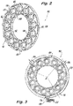
- frame 101 includes inner and outer combustor dome rings 132 and 130.
- Fuel manifold 118 can form the outer combustor dome ring 130, wherein the nozzle components 122 extend inward from the outer combustor dome ring radially inward to an inner combustor dome ring 132.
- the inner combustor dome ring 132 is circumferentially segmented, with one segment per nozzle, to accommodate thermal expansion and contraction of the combustor dome.
- Another way of accommodating thermal expansion and contraction in combustor dome 102 in addition to or in lieu of segmenting inner ring 132 is to segment the entire combustor dome, e.g., along the dashed lines in Fig.
- each segment would have its own inlet 120 and separate manifold 118 for feeding its subset of nozzles.
- the structure of combustor dome 102 as shown in Figs. 2 and 3 can be fabricated and brazed, additively manufactured, e.g., complete with internal nozzle details, or can be produced using any other suitable processes.
- Combustion system 100 includes a plurality of tiles 134 mounted to the frame 101 of combustor dome 102 to fluidly separate a downstream side of the combustor dome 102 from an upstream side of the combustor dome 102.
- Nozzle components 122 of each nozzle include a downstream insulation shell 136 with standoffs 138 extending in a downstream direction D from the nozzle, i.e., the axial direction between the upstream and downstream sides of the combustor dome 102.
- the standoffs 138 spaces the tile 134 apart from the nozzle to maintain space defining an outer air circuit 140 of the nozzle between tile 134 and shell 136 of the nozzle, as indicated in Fig. 6 .
- each tile 134 is mounted around a respective one of the nozzles.
- the nozzle components 122 of each nozzle include a radial swirler 142 on the upstream side of combustor dome 102 in fluid communication with a nozzle outlet 144 on the downstream side of combustor dome 102.
- An inner air circuit 146 is defined from radial swirler 142 to nozzle outlet 144.
- Inner and outer air circuits 142 and 140 are configured to issue 40% to 50% of airflow passing through combustor dome 102 through the inner air circuit 146, and to issue 50% to 60% of the airflow through the outer air circuit 140, wherein the total airflow of the inner and outer airflow circuits does not exceed 100%.
- Struts 148 support each nozzle in the frame 101 of combustor dome 102 and only modestly obstruct flow, e.g., air discharged from compressor 116, only to the outer air circuit 140.
- the outer air circuit 140 and radial swirler 142 are unobstructed by struts 148.
- the radial channel 141 labeled in Figs. 4-6 forming the inlet for outer air circuit 140 is located intimate and proximate the upstream surface of tile 134 for cooling of the tile 134 by airflow passing into the outer air circuit 140.
- the proximity of the channel 141 of outer air circuit 140 ensures high flow along the upstream surface of tile 134 and this large quantity of air flowing radially into the nozzle scrubs the back side of the tile 134, cooling it from the back side before the air enters the combustion volume 108.
- This cooling flow is indicated schematically by the converging arrows in Fig. 7 .
- the back side wall 143 of radial swirler 142 can be made of a composite material, or any other suitable material.
- tile 134 has a segment-shaped profile with a radially outer perimeter 150 and opposed radially inner perimeter 152.
- the downstream surface of tile 134 that is shown in Fig. 8 defines a circular outlet 144 for the outer air circuit 140, so outlet 144 is dimensioned to conform to the requirement for nozzle air flow.
- tile 134 defines a converging frustoconical surface 154 that defines a portion of the outer air circuit 140 shown in Fig. 6 .
- Tile 134 is thus integrated into the nozzle as one of the nozzle components 122.
- Tile 134 includes radial slots 156 that receive the standoff 138 that are shown in Fig. 4 . Slots 156 maintain concentricity between the nozzle and tile 134.
- each tile 134 include a radial edge with a radially extending groove 158 defined therein.
- Each tile 134 also includes a radial edge with a radially extending tongue 160 thereon.
- each tile 134 engages circumferentially adjacent tiles 134 wherein the tongues 160 are engaged in the grooves 158.
- the tongue and groove arrangement allows circumferential positional adjustment of tiles 134, reducing or eliminating radial growth arising from thermal expansion, while maintaining a seal between the adjacent tiles 134.
- each tile 134 is confined axially with the combustor dome 102, i.e. against movement in the direction D indicated in Fig. 6 .
- the tiles 134 are confined axially by an outer bayonet ring 162 proximate the radially outer perimeter 150 defined by the tiles 134, and by an inner bayonet ring 164 proximate the radially inner perimeter 152 defined by the tiles 134. This allows tiles 134 to contract and expand radially under thermal cycles.
- Each of the bayonet rings 162 and 164 is a continuous ring, however it is also contemplated that split rings, or multiple ring segments could be used for one or both.
- Each of the bayonet rings 162 and 164 is interlocked with bayonet features in respective inner and outer rings 132 and 130 of the combustor dome 102 so that bayonet rings 162 and 164 can be engaged and disengaged from combustor dome 102 by rotation in the direction indicated by the double arrows in Fig. 11 .
- Fig. 12 shows a bayonet feature 166 of the outer ring 130 of frame 101 interlocked with a bayonet feature 168 of outer bayonet ring 162.
- the bayonet feature 168 of outer bayonet ring 162 can be introduced into and removed from outer ring 130 through notch 170 defined in outer ring 130.
- Inner bayonet ring 164 and inner ring 132 of frame 101 have a similar engagement with bayonet features 174 and 176, and notch 172, which are shown in Fig. 11 .
- Each nozzle has a corresponding arrangement of bayonet features 166, 168, 174, and 176, however it is also contemplated that some of the bayonet features can be eliminated as long as enough are included for secure tiles 134 in place.
- outer bayonet ring 162 slidingly supports cold side combustor liner 178 of the outer combustor wall 106.
- Inner bayonet ring 164 slidingly supports cold side combustor liner 180 of the inner combustor wall 104.
- outer bayonet ring 162 can form a cold side combustor liner of the outer combustor wall 106, e.g., by making outer bayonet ring 162 and liner 178 integral
- inner bayonet ring 164 can form a cold side combustor liner of the inner combustor wall 104, e.g., by making inner bayonet ring 164 integral and liner 180 integral.
- Bayonet rings 162 and 164 can be made of any suitable material including metallic or composite materials.
- any suitable material can be used for tiles 134, such as SiC, SiC ceramic matrix composite (CMC) material.
- SiC and SiC CMC materials are light weight and capable of withstanding very high temperatures typical of combustion without necessarily requiring active cooling. These materials conduct heat relatively well, so backside cooling as described above can be sufficient to protect against direct combustion heating. Adequate air flow through the nozzle provides sufficient backside cooling. These materials also simplify design due to their low coefficient of thermal expansion. Using a design with partitioned tiles as described herein helps decouple thermal growth differentials between the outer ring of the combustor dome and the tiles. The components of combustor dome arrangements described herein tend to be loaded in the axial direction, pushing the components together axially. Composite materials perform favorably under such loading.
- the nozzles and combustor domes described herein provide many potential advantages over the traditional configurations.
- the fuel nozzles can now integrate a large majority of the combustor and fuel manifold into the nozzle structure.
- the nozzles and combustor dome can be engineered for maintenance/replacement to coincide with the replacement of other engine components such as turbines, where the engine case must be opened. Therefore, the nozzles do not need to be small enough to be extracted through the case and combustor.
- the larger nozzles can provide advantages including more efficient mixing large amounts of fuel and air, and the nozzle air can be used to cool the combustor, simplifying combustor design.
- the combustor itself can be substantially simplified with combustor domes such as disclosed herein.
- Thermal mismatch between the combustor and engine case can be decoupled from the nozzle/combustor interface.
- the weight of heavy stems (feed arms or the like), flanges, and engine case reinforcement can be reduced or eliminated.
- Common features between the nozzles and combustor can be unitized for construction.
Landscapes
- Engineering & Computer Science (AREA)
- Chemical & Material Sciences (AREA)
- Combustion & Propulsion (AREA)
- Mechanical Engineering (AREA)
- General Engineering & Computer Science (AREA)
- Spray-Type Burners (AREA)
Claims (9)
- Verbrennungssystem (100), umfassend:
einen Brennkammerdom (102), der eine Vielzahl von in Umfangsrichtung beabstandeten Düsen beinhaltet; eine Vielzahl von Platten (134), die an dem Brennkammerdom (102) montiert sind, um eine stromabwärtige Seite des Brennkammerdoms von einer stromaufwärtigen Seite des Brennkammerdoms fluidmäßig zu trennen; und wobei jede Platte (134) axial mit dem Brennkammerdom (102) begrenzt ist, und wobei die Platten (134) axial durch einen äußeren Bajonettring (162) nahe einem radial äußeren Umfang, der durch die Platten definiert ist, und durch einen inneren Bajonettring (164) nahe einem radial inneren Umfang, der durch die Platten definiert ist, begrenzt sind, wobei jeder der Bajonettringe (162, 164) mit Bajonettmerkmalen in dem jeweiligen inneren und äußeren Ring des Brennkammerdoms (102) verriegelt ist. - Verbrennungssystem nach Anspruch 1, wobei jede Platte (134) um eine jeweilige der Düsen montiert ist.
- Verbrennungssystem nach Anspruch 2, wobei jede Platte (134) von der jeweiligen der Düsen in einer axialen Richtung zwischen der stromaufwärtigen und der stromabwärtigen Seite des Brennkammerdoms (102) beabstandet ist, um einen äußeren Luftkreislauf (140) zwischen der Platte (134) und der jeweiligen der Düsen zu definieren.
- Verbrennungssystem nach Anspruch 3, wobei jede Düse einen radialen Verwirbler (142) an der stromaufwärtigen Seite des Brennkammerdoms (102) in Fluidverbindung mit einem Düsenauslass auf der stromabwärtigen Seite des Brennkammerdoms (102) beinhaltet, wobei ein innerer Luftkreislauf von dem radialen Verwirbler (142) zum Düsenauslass definiert ist, wobei der innere und der äußere Luftkreislauf so konfiguriert sind, dass sie 40 % bis 50 % des Luftstroms, der durch den Brennkammerdom (102) strömt, durch den inneren Luftkreislauf ausgeben, und 50 % bis 60 % des Luftstroms durch den äußeren Luftkreislauf (140) ausgeben, wobei der gesamte Luftstrom des inneren und des äußeren Luftkreislaufs 100 % nicht überschreitet.
- Verbrennungssystem nach Anspruch 4, wobei ein Kanal, der den Einlass des äußeren Luftkreislaufs bildet, nahe einer stromaufwärtigen Fläche der Platte zum Kühlen der Platte durch einen Luftstrom, der in den radialen Verwirbler (142) eintritt, liegt.
- Verbrennungssystem nach Anspruch 1, wobei jede Platte (134) eine radiale Kante mit einer radial verlaufenden Rinne (158), die darin definiert ist, beinhaltet, wobei jede Platte (134) eine radiale Kante mit einem radial verlaufenden Ansatz (160) daran beinhaltet, und wobei jede Platte (134) in Umfangsrichtung angrenzende Nachbarplatten (134) in Eingriff nimmt, wobei die Ansätze (160) mit den Rinnen (158) im Eingriff stehen.
- Verbrennungssystem nach einem der vorstehenden Ansprüche, wobei jede Platte (134) ein Material aus Keramikmatrix-Verbundwerkstoff (ceramic matrix composite - CMC) beinhaltet.
- Brennkammer für ein Gasturbinentriebwerk, umfassend:eine innere Brennkammerwand (104);eine äußere Brennkammerwand (106) radial außerhalb der inneren Brennkammerwand, wobei die innere und die äußere Brennkammerwand einen Brennraum dazwischen mit einem stromaufwärtigen Einlass (110) und einem stromabwärtigen Auslass (112) definieren; undund einen Brennkammerdom (102), der eine Verbindung zwischen einer inneren und einer äußeren Brennkammerwand (104, 106) an dem stromaufwärtigen Einlass (110) des Brennraums herstellt, wobei der Brennkammerdom (102) eine Vielzahl von in Umfangsrichtung beabstandeten Düsen und eine Vielzahl von Platten (134), die an dem Brennkammerdom (102) montiert sind, beinhaltet, um eine stromabwärtige Seite des Brennkammerdoms (102) von einer stromaufwärtigen Seite des Brennkammerdoms (102) fluidmäßig zu trennen; undwobei die Platten (134) axial durch einen äußeren Bajonettring (162) nahe einem radial äußeren Umfang, der durch die Platten definiert ist, und durch einen inneren Bajonettring (164) nahe einem radial inneren Umfang, der durch die Platten definiert ist, begrenzt sind, wobei jeder der Bajonettringe (162, 164) mit Bajonettmerkmalen im jeweiligen inneren und äußeren Ring des Brennkammerdoms (102) verriegelt ist, wobei der äußere Bajonettring (162) gleitend einen Kaltseitenbrennkammereinsatz der äußeren Brennkammerwand (106) stützt, und wobei der innere Bajonettring (164) gleitend einen Kaltseitenbrennkammereinsatz der inneren Brennkammerwand (104) stützt.
- Brennkammer für ein Gasturbinentriebwerk, umfassend:eine innere Brennkammerwand (104);eine äußere Brennkammerwand (106) radial außerhalb der inneren Brennkammerwand, wobei die innere und die äußere Brennkammerwand einen Brennraum dazwischen mit einem stromaufwärtigen Einlass (110) und einem stromabwärtigen Auslass (112) definieren; undund einen Brennkammerdom (102), der eine Verbindung zwischen einer inneren und einer äußeren Brennkammerwand (104, 106) an dem stromaufwärtigen Einlass (110) des Brennraums herstellt, wobei der Brennkammerdom (102) eine Vielzahl von in Umfangsrichtung beabstandeten Düsen und eine Vielzahl von Platten (134), die an dem Brennkammerdom (102) montiert sind, beinhaltet, um eine stromabwärtige Seite des Brennkammerdoms (102) von einer stromaufwärtigen Seite des Brennkammerdoms (102) fluidmäßig zu trennen; undwobei die Platten (134) axial durch einen äußeren Bajonettring (162) nahe einem radial äußeren Umfang, der durch die Platten definiert ist, und durch einen inneren Bajonettring (164) nahe einem radial inneren Umfang, der durch die Platten definiert ist, begrenzt sind, wobei jeder der Bajonettringe (162, 164) mit Bajonettmerkmalen im jeweiligen inneren und äußeren Ring des Brennkammerdoms (102) verriegelt ist, wobei der äußere Bajonettring (162) einen Kaltseitenbrennkammereinsatz der äußeren Brennkammerwand (106) bildet, und wobei der innere Bajonettring (164) einen Kaltseitenbrennkammereinsatz der inneren Brennkammerwand (104) bildet.
Applications Claiming Priority (2)
| Application Number | Priority Date | Filing Date | Title |
|---|---|---|---|
| US14/749,275 US10041679B2 (en) | 2015-06-24 | 2015-06-24 | Combustion systems |
| EP16175884.2A EP3109557B1 (de) | 2015-06-24 | 2016-06-23 | Verbrennungssysteme |
Related Parent Applications (1)
| Application Number | Title | Priority Date | Filing Date |
|---|---|---|---|
| EP16175884.2A Division EP3109557B1 (de) | 2015-06-24 | 2016-06-23 | Verbrennungssysteme |
Publications (3)
| Publication Number | Publication Date |
|---|---|
| EP3495737A2 EP3495737A2 (de) | 2019-06-12 |
| EP3495737A3 EP3495737A3 (de) | 2019-07-31 |
| EP3495737B1 true EP3495737B1 (de) | 2021-08-04 |
Family
ID=56194387
Family Applications (2)
| Application Number | Title | Priority Date | Filing Date |
|---|---|---|---|
| EP19153956.8A Active EP3495737B1 (de) | 2015-06-24 | 2016-06-23 | Verbrennungssysteme |
| EP16175884.2A Active EP3109557B1 (de) | 2015-06-24 | 2016-06-23 | Verbrennungssysteme |
Family Applications After (1)
| Application Number | Title | Priority Date | Filing Date |
|---|---|---|---|
| EP16175884.2A Active EP3109557B1 (de) | 2015-06-24 | 2016-06-23 | Verbrennungssysteme |
Country Status (2)
| Country | Link |
|---|---|
| US (2) | US10041679B2 (de) |
| EP (2) | EP3495737B1 (de) |
Families Citing this family (15)
| Publication number | Priority date | Publication date | Assignee | Title |
|---|---|---|---|---|
| US20160298853A1 (en) * | 2015-04-09 | 2016-10-13 | Siemens Energy, Inc. | Service-friendly cross flame tube with twist lock attachment for can-annular gas turbines |
| US10041679B2 (en) * | 2015-06-24 | 2018-08-07 | Delavan Inc | Combustion systems |
| US10663167B2 (en) * | 2017-06-16 | 2020-05-26 | General Electric Company | Combustor assembly with CMC combustor dome |
| CN109210528B (zh) * | 2017-06-29 | 2024-03-29 | 中国科学院过程工程研究所 | 一种解耦燃烧装置及燃烧方法 |
| US10731859B2 (en) * | 2017-07-21 | 2020-08-04 | Delavan Inc. | Fuel nozzles |
| US11339966B2 (en) * | 2018-08-21 | 2022-05-24 | General Electric Company | Flow control wall for heat engine |
| US11280492B2 (en) | 2018-08-23 | 2022-03-22 | General Electric Company | Combustor assembly for a turbo machine |
| US11408609B2 (en) * | 2018-10-26 | 2022-08-09 | Collins Engine Nozzles, Inc. | Combustor dome tiles |
| FR3084731B1 (fr) * | 2019-02-19 | 2020-07-03 | Safran Aircraft Engines | Chambre de combustion pour une turbomachine |
| GB201904330D0 (en) | 2019-03-28 | 2019-05-15 | Rolls Royce Plc | Gas turbine engine combuster apparatus |
| US11187155B2 (en) | 2019-07-22 | 2021-11-30 | Delavan Inc. | Sectional fuel manifolds |
| US11859819B2 (en) | 2021-10-15 | 2024-01-02 | General Electric Company | Ceramic composite combustor dome and liners |
| US12031486B2 (en) | 2022-01-13 | 2024-07-09 | General Electric Company | Combustor with lean openings |
| US12209750B2 (en) * | 2023-02-14 | 2025-01-28 | Collins Engine Nozzles, Inc. | Line replaceable fuel injector panels with single hatch installation |
| US20250207775A1 (en) * | 2023-12-22 | 2025-06-26 | General Electric Company | Turbine engine having a combustion section with a fuel nozzle |
Family Cites Families (22)
| Publication number | Priority date | Publication date | Assignee | Title |
|---|---|---|---|---|
| FR2686683B1 (fr) * | 1992-01-28 | 1994-04-01 | Snecma | Turbomachine a chambre de combustion demontable. |
| US5353599A (en) * | 1993-04-29 | 1994-10-11 | United Technologies Corporation | Fuel nozzle swirler for combustors |
| US5419115A (en) * | 1994-04-29 | 1995-05-30 | United Technologies Corporation | Bulkhead and fuel nozzle guide assembly for an annular combustion chamber |
| US5816049A (en) * | 1997-01-02 | 1998-10-06 | General Electric Company | Dual fuel mixer for gas turbine combustor |
| US5966937A (en) * | 1997-10-09 | 1999-10-19 | United Technologies Corporation | Radial inlet swirler with twisted vanes for fuel injector |
| US6164074A (en) | 1997-12-12 | 2000-12-26 | United Technologies Corporation | Combustor bulkhead with improved cooling and air recirculation zone |
| US6334298B1 (en) * | 2000-07-14 | 2002-01-01 | General Electric Company | Gas turbine combustor having dome-to-liner joint |
| DE10219354A1 (de) * | 2002-04-30 | 2003-11-13 | Rolls Royce Deutschland | Gasturbinenbrennkammer mit gezielter Kraftstoffeinbringung zur Verbesserung der Homogenität des Kraftstoff-Luft-Gemisches |
| US6983599B2 (en) * | 2004-02-12 | 2006-01-10 | General Electric Company | Combustor member and method for making a combustor assembly |
| US7596949B2 (en) * | 2006-02-23 | 2009-10-06 | General Electric Company | Method and apparatus for heat shielding gas turbine engines |
| FR2897922B1 (fr) * | 2006-02-27 | 2008-10-10 | Snecma Sa | Agencement pour une chambre de combustion de turboreacteur |
| US7856826B2 (en) * | 2006-11-10 | 2010-12-28 | General Electric Company | Combustor dome mixer retaining means |
| US7748221B2 (en) | 2006-11-17 | 2010-07-06 | Pratt & Whitney Canada Corp. | Combustor heat shield with variable cooling |
| FR2918444B1 (fr) * | 2007-07-05 | 2013-06-28 | Snecma | Deflecteur de fond de chambre, chambre de combustion le comportant et moteur a turbine a gaz en etant equipe |
| WO2011092779A1 (ja) | 2010-01-28 | 2011-08-04 | 川崎重工業株式会社 | ガスタービン燃焼器 |
| JP4838888B2 (ja) * | 2009-05-27 | 2011-12-14 | 川崎重工業株式会社 | ガスタービン燃焼器 |
| US8365533B2 (en) | 2009-09-22 | 2013-02-05 | General Electric Company | Universal multi-nozzle combustion system and method |
| US8943835B2 (en) * | 2010-05-10 | 2015-02-03 | General Electric Company | Gas turbine engine combustor with CMC heat shield and methods therefor |
| US8726669B2 (en) * | 2011-06-30 | 2014-05-20 | General Electric Company | Combustor dome with combined deflector/mixer retainer |
| US8893382B2 (en) | 2011-09-30 | 2014-11-25 | General Electric Company | Combustion system and method of assembling the same |
| WO2015023576A1 (en) * | 2013-08-15 | 2015-02-19 | United Technologies Corporation | Protective panel and frame therefor |
| US10041679B2 (en) * | 2015-06-24 | 2018-08-07 | Delavan Inc | Combustion systems |
-
2015
- 2015-06-24 US US14/749,275 patent/US10041679B2/en active Active
-
2016
- 2016-06-23 EP EP19153956.8A patent/EP3495737B1/de active Active
- 2016-06-23 EP EP16175884.2A patent/EP3109557B1/de active Active
-
2018
- 2018-04-09 US US15/948,482 patent/US10830440B2/en active Active
Non-Patent Citations (1)
| Title |
|---|
| None * |
Also Published As
| Publication number | Publication date |
|---|---|
| US20180224125A1 (en) | 2018-08-09 |
| EP3495737A2 (de) | 2019-06-12 |
| US10041679B2 (en) | 2018-08-07 |
| US20160377292A1 (en) | 2016-12-29 |
| EP3109557A2 (de) | 2016-12-28 |
| US10830440B2 (en) | 2020-11-10 |
| EP3109557B1 (de) | 2019-01-30 |
| EP3495737A3 (de) | 2019-07-31 |
| EP3109557A3 (de) | 2017-03-15 |
Similar Documents
| Publication | Publication Date | Title |
|---|---|---|
| US10830440B2 (en) | Combustion systems having bayonet features | |
| EP3109548B1 (de) | Verbrennungssysteme mit im brennkammerdom integriertem brennstoffverteiler | |
| EP3553383B1 (de) | Kraftstoffinjektoren für turbomaschinen | |
| EP3382280B1 (de) | Kraftstoffinjektoren für mehrpunktarrays | |
| EP3671039B1 (de) | Mehrpunktkraftstoffeinspritzsystem mit hitzeschild | |
| CN101551122B (zh) | 陶瓷基复合材料制成且细分为多区域的燃气涡轮机燃烧室 | |
| EP3431878B1 (de) | Kraftstoffdüsen | |
| US11466855B2 (en) | Gas turbine engine combustor with ceramic matrix composite liner | |
| EP3553293B1 (de) | Brennstoffverteilersystem für turbomaschinen | |
| EP2902605B1 (de) | Brennstoffverteilerleitung und Kraftstoffeinspritzanordnung für eine Gasturbine | |
| EP3643969B1 (de) | Mehrpunkteinspritzungssystem für eine gasturbinenbrennkammer | |
| EP3598003B1 (de) | Mehrpunkteinspritzungssystem | |
| US11585275B2 (en) | Internal manifold for multipoint injection | |
| US11674687B2 (en) | Fuel manifolds | |
| EP4137689A1 (de) | Luftverteiler für kraftstoffeinspritzdüsen mit kraftstoff-luft-wärmetauschern | |
| US11852344B2 (en) | Tubular combustion chamber system and gas turbine unit having a tubular combustion chamber system of this type |
Legal Events
| Date | Code | Title | Description |
|---|---|---|---|
| PUAI | Public reference made under article 153(3) epc to a published international application that has entered the european phase |
Free format text: ORIGINAL CODE: 0009012 |
|
| STAA | Information on the status of an ep patent application or granted ep patent |
Free format text: STATUS: THE APPLICATION HAS BEEN PUBLISHED |
|
| AC | Divisional application: reference to earlier application |
Ref document number: 3109557 Country of ref document: EP Kind code of ref document: P |
|
| AK | Designated contracting states |
Kind code of ref document: A2 Designated state(s): AL AT BE BG CH CY CZ DE DK EE ES FI FR GB GR HR HU IE IS IT LI LT LU LV MC MK MT NL NO PL PT RO RS SE SI SK SM TR |
|
| PUAL | Search report despatched |
Free format text: ORIGINAL CODE: 0009013 |
|
| AK | Designated contracting states |
Kind code of ref document: A3 Designated state(s): AL AT BE BG CH CY CZ DE DK EE ES FI FR GB GR HR HU IE IS IT LI LT LU LV MC MK MT NL NO PL PT RO RS SE SI SK SM TR |
|
| RIC1 | Information provided on ipc code assigned before grant |
Ipc: F23R 3/50 20060101AFI20190621BHEP Ipc: F23R 3/60 20060101ALI20190621BHEP |
|
| STAA | Information on the status of an ep patent application or granted ep patent |
Free format text: STATUS: REQUEST FOR EXAMINATION WAS MADE |
|
| 17P | Request for examination filed |
Effective date: 20191121 |
|
| RBV | Designated contracting states (corrected) |
Designated state(s): AL AT BE BG CH CY CZ DE DK EE ES FI FR GB GR HR HU IE IS IT LI LT LU LV MC MK MT NL NO PL PT RO RS SE SI SK SM TR |
|
| STAA | Information on the status of an ep patent application or granted ep patent |
Free format text: STATUS: EXAMINATION IS IN PROGRESS |
|
| 17Q | First examination report despatched |
Effective date: 20200330 |
|
| GRAP | Despatch of communication of intention to grant a patent |
Free format text: ORIGINAL CODE: EPIDOSNIGR1 |
|
| STAA | Information on the status of an ep patent application or granted ep patent |
Free format text: STATUS: GRANT OF PATENT IS INTENDED |
|
| INTG | Intention to grant announced |
Effective date: 20210114 |
|
| GRAS | Grant fee paid |
Free format text: ORIGINAL CODE: EPIDOSNIGR3 |
|
| GRAA | (expected) grant |
Free format text: ORIGINAL CODE: 0009210 |
|
| STAA | Information on the status of an ep patent application or granted ep patent |
Free format text: STATUS: THE PATENT HAS BEEN GRANTED |
|
| AC | Divisional application: reference to earlier application |
Ref document number: 3109557 Country of ref document: EP Kind code of ref document: P |
|
| AK | Designated contracting states |
Kind code of ref document: B1 Designated state(s): AL AT BE BG CH CY CZ DE DK EE ES FI FR GB GR HR HU IE IS IT LI LT LU LV MC MK MT NL NO PL PT RO RS SE SI SK SM TR |
|
| REG | Reference to a national code |
Ref country code: GB Ref legal event code: FG4D |
|
| REG | Reference to a national code |
Ref country code: AT Ref legal event code: REF Ref document number: 1417347 Country of ref document: AT Kind code of ref document: T Effective date: 20210815 |
|
| REG | Reference to a national code |
Ref country code: CH Ref legal event code: EP |
|
| REG | Reference to a national code |
Ref country code: DE Ref legal event code: R096 Ref document number: 602016061847 Country of ref document: DE |
|
| REG | Reference to a national code |
Ref country code: IE Ref legal event code: FG4D |
|
| REG | Reference to a national code |
Ref country code: LT Ref legal event code: MG9D |
|
| REG | Reference to a national code |
Ref country code: NL Ref legal event code: MP Effective date: 20210804 |
|
| REG | Reference to a national code |
Ref country code: AT Ref legal event code: MK05 Ref document number: 1417347 Country of ref document: AT Kind code of ref document: T Effective date: 20210804 |
|
| PG25 | Lapsed in a contracting state [announced via postgrant information from national office to epo] |
Ref country code: RS Free format text: LAPSE BECAUSE OF FAILURE TO SUBMIT A TRANSLATION OF THE DESCRIPTION OR TO PAY THE FEE WITHIN THE PRESCRIBED TIME-LIMIT Effective date: 20210804 Ref country code: SE Free format text: LAPSE BECAUSE OF FAILURE TO SUBMIT A TRANSLATION OF THE DESCRIPTION OR TO PAY THE FEE WITHIN THE PRESCRIBED TIME-LIMIT Effective date: 20210804 Ref country code: ES Free format text: LAPSE BECAUSE OF FAILURE TO SUBMIT A TRANSLATION OF THE DESCRIPTION OR TO PAY THE FEE WITHIN THE PRESCRIBED TIME-LIMIT Effective date: 20210804 Ref country code: FI Free format text: LAPSE BECAUSE OF FAILURE TO SUBMIT A TRANSLATION OF THE DESCRIPTION OR TO PAY THE FEE WITHIN THE PRESCRIBED TIME-LIMIT Effective date: 20210804 Ref country code: NO Free format text: LAPSE BECAUSE OF FAILURE TO SUBMIT A TRANSLATION OF THE DESCRIPTION OR TO PAY THE FEE WITHIN THE PRESCRIBED TIME-LIMIT Effective date: 20211104 Ref country code: PT Free format text: LAPSE BECAUSE OF FAILURE TO SUBMIT A TRANSLATION OF THE DESCRIPTION OR TO PAY THE FEE WITHIN THE PRESCRIBED TIME-LIMIT Effective date: 20211206 Ref country code: HR Free format text: LAPSE BECAUSE OF FAILURE TO SUBMIT A TRANSLATION OF THE DESCRIPTION OR TO PAY THE FEE WITHIN THE PRESCRIBED TIME-LIMIT Effective date: 20210804 Ref country code: AT Free format text: LAPSE BECAUSE OF FAILURE TO SUBMIT A TRANSLATION OF THE DESCRIPTION OR TO PAY THE FEE WITHIN THE PRESCRIBED TIME-LIMIT Effective date: 20210804 Ref country code: BG Free format text: LAPSE BECAUSE OF FAILURE TO SUBMIT A TRANSLATION OF THE DESCRIPTION OR TO PAY THE FEE WITHIN THE PRESCRIBED TIME-LIMIT Effective date: 20211104 Ref country code: LT Free format text: LAPSE BECAUSE OF FAILURE TO SUBMIT A TRANSLATION OF THE DESCRIPTION OR TO PAY THE FEE WITHIN THE PRESCRIBED TIME-LIMIT Effective date: 20210804 |
|
| PG25 | Lapsed in a contracting state [announced via postgrant information from national office to epo] |
Ref country code: PL Free format text: LAPSE BECAUSE OF FAILURE TO SUBMIT A TRANSLATION OF THE DESCRIPTION OR TO PAY THE FEE WITHIN THE PRESCRIBED TIME-LIMIT Effective date: 20210804 Ref country code: LV Free format text: LAPSE BECAUSE OF FAILURE TO SUBMIT A TRANSLATION OF THE DESCRIPTION OR TO PAY THE FEE WITHIN THE PRESCRIBED TIME-LIMIT Effective date: 20210804 Ref country code: GR Free format text: LAPSE BECAUSE OF FAILURE TO SUBMIT A TRANSLATION OF THE DESCRIPTION OR TO PAY THE FEE WITHIN THE PRESCRIBED TIME-LIMIT Effective date: 20211105 |
|
| PG25 | Lapsed in a contracting state [announced via postgrant information from national office to epo] |
Ref country code: NL Free format text: LAPSE BECAUSE OF FAILURE TO SUBMIT A TRANSLATION OF THE DESCRIPTION OR TO PAY THE FEE WITHIN THE PRESCRIBED TIME-LIMIT Effective date: 20210804 |
|
| PG25 | Lapsed in a contracting state [announced via postgrant information from national office to epo] |
Ref country code: DK Free format text: LAPSE BECAUSE OF FAILURE TO SUBMIT A TRANSLATION OF THE DESCRIPTION OR TO PAY THE FEE WITHIN THE PRESCRIBED TIME-LIMIT Effective date: 20210804 |
|
| REG | Reference to a national code |
Ref country code: DE Ref legal event code: R097 Ref document number: 602016061847 Country of ref document: DE |
|
| RAP4 | Party data changed (patent owner data changed or rights of a patent transferred) |
Owner name: COLLINS ENGINE NOZZLES, INC. |
|
| PG25 | Lapsed in a contracting state [announced via postgrant information from national office to epo] |
Ref country code: SM Free format text: LAPSE BECAUSE OF FAILURE TO SUBMIT A TRANSLATION OF THE DESCRIPTION OR TO PAY THE FEE WITHIN THE PRESCRIBED TIME-LIMIT Effective date: 20210804 Ref country code: SK Free format text: LAPSE BECAUSE OF FAILURE TO SUBMIT A TRANSLATION OF THE DESCRIPTION OR TO PAY THE FEE WITHIN THE PRESCRIBED TIME-LIMIT Effective date: 20210804 Ref country code: RO Free format text: LAPSE BECAUSE OF FAILURE TO SUBMIT A TRANSLATION OF THE DESCRIPTION OR TO PAY THE FEE WITHIN THE PRESCRIBED TIME-LIMIT Effective date: 20210804 Ref country code: EE Free format text: LAPSE BECAUSE OF FAILURE TO SUBMIT A TRANSLATION OF THE DESCRIPTION OR TO PAY THE FEE WITHIN THE PRESCRIBED TIME-LIMIT Effective date: 20210804 Ref country code: CZ Free format text: LAPSE BECAUSE OF FAILURE TO SUBMIT A TRANSLATION OF THE DESCRIPTION OR TO PAY THE FEE WITHIN THE PRESCRIBED TIME-LIMIT Effective date: 20210804 Ref country code: AL Free format text: LAPSE BECAUSE OF FAILURE TO SUBMIT A TRANSLATION OF THE DESCRIPTION OR TO PAY THE FEE WITHIN THE PRESCRIBED TIME-LIMIT Effective date: 20210804 |
|
| PLBE | No opposition filed within time limit |
Free format text: ORIGINAL CODE: 0009261 |
|
| STAA | Information on the status of an ep patent application or granted ep patent |
Free format text: STATUS: NO OPPOSITION FILED WITHIN TIME LIMIT |
|
| 26N | No opposition filed |
Effective date: 20220506 |
|
| PG25 | Lapsed in a contracting state [announced via postgrant information from national office to epo] |
Ref country code: IT Free format text: LAPSE BECAUSE OF FAILURE TO SUBMIT A TRANSLATION OF THE DESCRIPTION OR TO PAY THE FEE WITHIN THE PRESCRIBED TIME-LIMIT Effective date: 20210804 |
|
| PG25 | Lapsed in a contracting state [announced via postgrant information from national office to epo] |
Ref country code: SI Free format text: LAPSE BECAUSE OF FAILURE TO SUBMIT A TRANSLATION OF THE DESCRIPTION OR TO PAY THE FEE WITHIN THE PRESCRIBED TIME-LIMIT Effective date: 20210804 |
|
| PG25 | Lapsed in a contracting state [announced via postgrant information from national office to epo] |
Ref country code: MC Free format text: LAPSE BECAUSE OF FAILURE TO SUBMIT A TRANSLATION OF THE DESCRIPTION OR TO PAY THE FEE WITHIN THE PRESCRIBED TIME-LIMIT Effective date: 20210804 |
|
| REG | Reference to a national code |
Ref country code: CH Ref legal event code: PL |
|
| REG | Reference to a national code |
Ref country code: BE Ref legal event code: MM Effective date: 20220630 |
|
| PG25 | Lapsed in a contracting state [announced via postgrant information from national office to epo] |
Ref country code: LU Free format text: LAPSE BECAUSE OF NON-PAYMENT OF DUE FEES Effective date: 20220623 Ref country code: LI Free format text: LAPSE BECAUSE OF NON-PAYMENT OF DUE FEES Effective date: 20220630 Ref country code: IE Free format text: LAPSE BECAUSE OF NON-PAYMENT OF DUE FEES Effective date: 20220623 Ref country code: CH Free format text: LAPSE BECAUSE OF NON-PAYMENT OF DUE FEES Effective date: 20220630 |
|
| PG25 | Lapsed in a contracting state [announced via postgrant information from national office to epo] |
Ref country code: BE Free format text: LAPSE BECAUSE OF NON-PAYMENT OF DUE FEES Effective date: 20220630 |
|
| P01 | Opt-out of the competence of the unified patent court (upc) registered |
Effective date: 20230530 |
|
| PG25 | Lapsed in a contracting state [announced via postgrant information from national office to epo] |
Ref country code: HU Free format text: LAPSE BECAUSE OF FAILURE TO SUBMIT A TRANSLATION OF THE DESCRIPTION OR TO PAY THE FEE WITHIN THE PRESCRIBED TIME-LIMIT; INVALID AB INITIO Effective date: 20160623 |
|
| PG25 | Lapsed in a contracting state [announced via postgrant information from national office to epo] |
Ref country code: MK Free format text: LAPSE BECAUSE OF FAILURE TO SUBMIT A TRANSLATION OF THE DESCRIPTION OR TO PAY THE FEE WITHIN THE PRESCRIBED TIME-LIMIT Effective date: 20210804 Ref country code: CY Free format text: LAPSE BECAUSE OF FAILURE TO SUBMIT A TRANSLATION OF THE DESCRIPTION OR TO PAY THE FEE WITHIN THE PRESCRIBED TIME-LIMIT Effective date: 20210804 |
|
| PG25 | Lapsed in a contracting state [announced via postgrant information from national office to epo] |
Ref country code: TR Free format text: LAPSE BECAUSE OF FAILURE TO SUBMIT A TRANSLATION OF THE DESCRIPTION OR TO PAY THE FEE WITHIN THE PRESCRIBED TIME-LIMIT Effective date: 20210804 |
|
| PG25 | Lapsed in a contracting state [announced via postgrant information from national office to epo] |
Ref country code: MT Free format text: LAPSE BECAUSE OF FAILURE TO SUBMIT A TRANSLATION OF THE DESCRIPTION OR TO PAY THE FEE WITHIN THE PRESCRIBED TIME-LIMIT Effective date: 20210804 |
|
| PGFP | Annual fee paid to national office [announced via postgrant information from national office to epo] |
Ref country code: DE Payment date: 20250520 Year of fee payment: 10 |
|
| PGFP | Annual fee paid to national office [announced via postgrant information from national office to epo] |
Ref country code: GB Payment date: 20250520 Year of fee payment: 10 |
|
| PGFP | Annual fee paid to national office [announced via postgrant information from national office to epo] |
Ref country code: FR Payment date: 20250520 Year of fee payment: 10 |