EP3495796A2 - Dispositif et procédé de vérification d'un adaptateur de charge pour fournir de l'énergie électrique à un stockage d'énergie d'un véhicule - Google Patents
Dispositif et procédé de vérification d'un adaptateur de charge pour fournir de l'énergie électrique à un stockage d'énergie d'un véhicule Download PDFInfo
- Publication number
- EP3495796A2 EP3495796A2 EP18210292.1A EP18210292A EP3495796A2 EP 3495796 A2 EP3495796 A2 EP 3495796A2 EP 18210292 A EP18210292 A EP 18210292A EP 3495796 A2 EP3495796 A2 EP 3495796A2
- Authority
- EP
- European Patent Office
- Prior art keywords
- fluid
- charging socket
- cable
- pressure
- flow rate
- Prior art date
- Legal status (The legal status is an assumption and is not a legal conclusion. Google has not performed a legal analysis and makes no representation as to the accuracy of the status listed.)
- Granted
Links
Images

Classifications
-
- G—PHYSICS
- G01—MEASURING; TESTING
- G01M—TESTING STATIC OR DYNAMIC BALANCE OF MACHINES OR STRUCTURES; TESTING OF STRUCTURES OR APPARATUS, NOT OTHERWISE PROVIDED FOR
- G01M3/00—Investigating fluid-tightness of structures
- G01M3/02—Investigating fluid-tightness of structures by using fluid or vacuum
- G01M3/26—Investigating fluid-tightness of structures by using fluid or vacuum by measuring rate of loss or gain of fluid, e.g. by pressure-responsive devices, by flow detectors
- G01M3/28—Investigating fluid-tightness of structures by using fluid or vacuum by measuring rate of loss or gain of fluid, e.g. by pressure-responsive devices, by flow detectors for pipes, cables or tubes; for pipe joints or seals; for valves ; for welds
- G01M3/2838—Investigating fluid-tightness of structures by using fluid or vacuum by measuring rate of loss or gain of fluid, e.g. by pressure-responsive devices, by flow detectors for pipes, cables or tubes; for pipe joints or seals; for valves ; for welds for cables
-
- G—PHYSICS
- G01—MEASURING; TESTING
- G01R—MEASURING ELECTRIC VARIABLES; MEASURING MAGNETIC VARIABLES
- G01R31/00—Arrangements for testing electric properties; Arrangements for locating electric faults; Arrangements for electrical testing characterised by what is being tested not provided for elsewhere
- G01R31/50—Testing of electric apparatus, lines, cables or components for short-circuits, continuity, leakage current or incorrect line connections
- G01R31/66—Testing of connections, e.g. of plugs or non-disconnectable joints
- G01R31/68—Testing of releasable connections, e.g. of terminals mounted on a printed circuit board
- G01R31/69—Testing of releasable connections, e.g. of terminals mounted on a printed circuit board of terminals at the end of a cable or a wire harness; of plugs; of sockets, e.g. wall sockets or power sockets in appliances
-
- B—PERFORMING OPERATIONS; TRANSPORTING
- B60—VEHICLES IN GENERAL
- B60L—PROPULSION OF ELECTRICALLY-PROPELLED VEHICLES; SUPPLYING ELECTRIC POWER FOR AUXILIARY EQUIPMENT OF ELECTRICALLY-PROPELLED VEHICLES; ELECTRODYNAMIC BRAKE SYSTEMS FOR VEHICLES IN GENERAL; MAGNETIC SUSPENSION OR LEVITATION FOR VEHICLES; MONITORING OPERATING VARIABLES OF ELECTRICALLY-PROPELLED VEHICLES; ELECTRIC SAFETY DEVICES FOR ELECTRICALLY-PROPELLED VEHICLES
- B60L53/00—Methods of charging batteries, specially adapted for electric vehicles; Charging stations or on-board charging equipment therefor; Exchange of energy storage elements in electric vehicles
- B60L53/10—Methods of charging batteries, specially adapted for electric vehicles; Charging stations or on-board charging equipment therefor; Exchange of energy storage elements in electric vehicles characterised by the energy transfer between the charging station and the vehicle
- B60L53/14—Conductive energy transfer
- B60L53/16—Connectors, e.g. plugs or sockets, specially adapted for charging electric vehicles
-
- G—PHYSICS
- G01—MEASURING; TESTING
- G01M—TESTING STATIC OR DYNAMIC BALANCE OF MACHINES OR STRUCTURES; TESTING OF STRUCTURES OR APPARATUS, NOT OTHERWISE PROVIDED FOR
- G01M3/00—Investigating fluid-tightness of structures
- G01M3/02—Investigating fluid-tightness of structures by using fluid or vacuum
- G01M3/04—Investigating fluid-tightness of structures by using fluid or vacuum by detecting the presence of fluid at the leakage point
-
- G—PHYSICS
- G01—MEASURING; TESTING
- G01M—TESTING STATIC OR DYNAMIC BALANCE OF MACHINES OR STRUCTURES; TESTING OF STRUCTURES OR APPARATUS, NOT OTHERWISE PROVIDED FOR
- G01M3/00—Investigating fluid-tightness of structures
- G01M3/02—Investigating fluid-tightness of structures by using fluid or vacuum
- G01M3/04—Investigating fluid-tightness of structures by using fluid or vacuum by detecting the presence of fluid at the leakage point
- G01M3/20—Investigating fluid-tightness of structures by using fluid or vacuum by detecting the presence of fluid at the leakage point using special tracer materials, e.g. dye, fluorescent material, radioactive material
- G01M3/22—Investigating fluid-tightness of structures by using fluid or vacuum by detecting the presence of fluid at the leakage point using special tracer materials, e.g. dye, fluorescent material, radioactive material for pipes, cables or tubes; for pipe joints or seals; for valves; for welds; for containers, e.g. radiators
- G01M3/226—Investigating fluid-tightness of structures by using fluid or vacuum by detecting the presence of fluid at the leakage point using special tracer materials, e.g. dye, fluorescent material, radioactive material for pipes, cables or tubes; for pipe joints or seals; for valves; for welds; for containers, e.g. radiators for containers, e.g. radiators
-
- G—PHYSICS
- G01—MEASURING; TESTING
- G01M—TESTING STATIC OR DYNAMIC BALANCE OF MACHINES OR STRUCTURES; TESTING OF STRUCTURES OR APPARATUS, NOT OTHERWISE PROVIDED FOR
- G01M3/00—Investigating fluid-tightness of structures
- G01M3/02—Investigating fluid-tightness of structures by using fluid or vacuum
- G01M3/26—Investigating fluid-tightness of structures by using fluid or vacuum by measuring rate of loss or gain of fluid, e.g. by pressure-responsive devices, by flow detectors
-
- G—PHYSICS
- G01—MEASURING; TESTING
- G01M—TESTING STATIC OR DYNAMIC BALANCE OF MACHINES OR STRUCTURES; TESTING OF STRUCTURES OR APPARATUS, NOT OTHERWISE PROVIDED FOR
- G01M3/00—Investigating fluid-tightness of structures
- G01M3/02—Investigating fluid-tightness of structures by using fluid or vacuum
- G01M3/26—Investigating fluid-tightness of structures by using fluid or vacuum by measuring rate of loss or gain of fluid, e.g. by pressure-responsive devices, by flow detectors
- G01M3/32—Investigating fluid-tightness of structures by using fluid or vacuum by measuring rate of loss or gain of fluid, e.g. by pressure-responsive devices, by flow detectors for containers, e.g. radiators
- G01M3/3236—Investigating fluid-tightness of structures by using fluid or vacuum by measuring rate of loss or gain of fluid, e.g. by pressure-responsive devices, by flow detectors for containers, e.g. radiators by monitoring the interior space of the containers
- G01M3/3254—Investigating fluid-tightness of structures by using fluid or vacuum by measuring rate of loss or gain of fluid, e.g. by pressure-responsive devices, by flow detectors for containers, e.g. radiators by monitoring the interior space of the containers using a flow detector
-
- G—PHYSICS
- G01—MEASURING; TESTING
- G01M—TESTING STATIC OR DYNAMIC BALANCE OF MACHINES OR STRUCTURES; TESTING OF STRUCTURES OR APPARATUS, NOT OTHERWISE PROVIDED FOR
- G01M3/00—Investigating fluid-tightness of structures
- G01M3/02—Investigating fluid-tightness of structures by using fluid or vacuum
- G01M3/26—Investigating fluid-tightness of structures by using fluid or vacuum by measuring rate of loss or gain of fluid, e.g. by pressure-responsive devices, by flow detectors
- G01M3/32—Investigating fluid-tightness of structures by using fluid or vacuum by measuring rate of loss or gain of fluid, e.g. by pressure-responsive devices, by flow detectors for containers, e.g. radiators
- G01M3/3236—Investigating fluid-tightness of structures by using fluid or vacuum by measuring rate of loss or gain of fluid, e.g. by pressure-responsive devices, by flow detectors for containers, e.g. radiators by monitoring the interior space of the containers
- G01M3/3272—Investigating fluid-tightness of structures by using fluid or vacuum by measuring rate of loss or gain of fluid, e.g. by pressure-responsive devices, by flow detectors for containers, e.g. radiators by monitoring the interior space of the containers for verifying the internal pressure of closed containers
-
- G—PHYSICS
- G01—MEASURING; TESTING
- G01M—TESTING STATIC OR DYNAMIC BALANCE OF MACHINES OR STRUCTURES; TESTING OF STRUCTURES OR APPARATUS, NOT OTHERWISE PROVIDED FOR
- G01M3/00—Investigating fluid-tightness of structures
- G01M3/38—Investigating fluid-tightness of structures by using light
-
- G—PHYSICS
- G01—MEASURING; TESTING
- G01R—MEASURING ELECTRIC VARIABLES; MEASURING MAGNETIC VARIABLES
- G01R31/00—Arrangements for testing electric properties; Arrangements for locating electric faults; Arrangements for electrical testing characterised by what is being tested not provided for elsewhere
- G01R31/50—Testing of electric apparatus, lines, cables or components for short-circuits, continuity, leakage current or incorrect line connections
- G01R31/66—Testing of connections, e.g. of plugs or non-disconnectable joints
-
- Y—GENERAL TAGGING OF NEW TECHNOLOGICAL DEVELOPMENTS; GENERAL TAGGING OF CROSS-SECTIONAL TECHNOLOGIES SPANNING OVER SEVERAL SECTIONS OF THE IPC; TECHNICAL SUBJECTS COVERED BY FORMER USPC CROSS-REFERENCE ART COLLECTIONS [XRACs] AND DIGESTS
- Y02—TECHNOLOGIES OR APPLICATIONS FOR MITIGATION OR ADAPTATION AGAINST CLIMATE CHANGE
- Y02T—CLIMATE CHANGE MITIGATION TECHNOLOGIES RELATED TO TRANSPORTATION
- Y02T10/00—Road transport of goods or passengers
- Y02T10/60—Other road transportation technologies with climate change mitigation effect
- Y02T10/70—Energy storage systems for electromobility, e.g. batteries
-
- Y—GENERAL TAGGING OF NEW TECHNOLOGICAL DEVELOPMENTS; GENERAL TAGGING OF CROSS-SECTIONAL TECHNOLOGIES SPANNING OVER SEVERAL SECTIONS OF THE IPC; TECHNICAL SUBJECTS COVERED BY FORMER USPC CROSS-REFERENCE ART COLLECTIONS [XRACs] AND DIGESTS
- Y02—TECHNOLOGIES OR APPLICATIONS FOR MITIGATION OR ADAPTATION AGAINST CLIMATE CHANGE
- Y02T—CLIMATE CHANGE MITIGATION TECHNOLOGIES RELATED TO TRANSPORTATION
- Y02T10/00—Road transport of goods or passengers
- Y02T10/60—Other road transportation technologies with climate change mitigation effect
- Y02T10/7072—Electromobility specific charging systems or methods for batteries, ultracapacitors, supercapacitors or double-layer capacitors
-
- Y—GENERAL TAGGING OF NEW TECHNOLOGICAL DEVELOPMENTS; GENERAL TAGGING OF CROSS-SECTIONAL TECHNOLOGIES SPANNING OVER SEVERAL SECTIONS OF THE IPC; TECHNICAL SUBJECTS COVERED BY FORMER USPC CROSS-REFERENCE ART COLLECTIONS [XRACs] AND DIGESTS
- Y02—TECHNOLOGIES OR APPLICATIONS FOR MITIGATION OR ADAPTATION AGAINST CLIMATE CHANGE
- Y02T—CLIMATE CHANGE MITIGATION TECHNOLOGIES RELATED TO TRANSPORTATION
- Y02T90/00—Enabling technologies or technologies with a potential or indirect contribution to GHG emissions mitigation
- Y02T90/10—Technologies relating to charging of electric vehicles
- Y02T90/14—Plug-in electric vehicles
Definitions
- the present invention relates to a device for testing a charging socket for supplying electrical energy to an energy storage device of a vehicle and to a method for testing a charging socket for supplying electrical energy to an energy storage device of a vehicle.
- the present invention will be described below mainly in connection with a vehicle high voltage wiring network. However, the invention can be used in any application in which electrical networks are to be tested for leaks and the electrical lines are used as compressed air lines.
- So-called plug-in hybrid vehicles (PHEV) and pure electric vehicles (BEV) each have a charging socket, via which the battery of the motor vehicle electrical energy can be supplied from outside.
- the supply can be done usually via normal household sockets or via fast charging stations.
- a charging socket in the sense of the present patent application can be understood in particular as a connection point of an at least partially electrically driven motor vehicle, in particular an electric or hybrid motor vehicle, to which an external charging line can be connected to a battery, also generally referred to as an energy store. the motor vehicle to supply electrical energy from outside the motor vehicle.
- Such a charging socket has a moisture-tight space surrounded by a wall, in which electrical contacts and control electronics can be arranged.
- a moisture-proof space can also be present on other electrical or electronic devices, for example in an electronic device of an industrial plant or the like to be arranged on a mounting rail, wherein electrical or electronic components, for example circuit arrangements on a printed circuit board or the like, can be arranged within such a moisture-proof space.
- Such a charging socket becomes part of a pipeline network comprising one or more sealed connectors which are connected by cables to the charging socket.
- the requirement is that moisture can not penetrate into the moisture-proof chamber via a connection for a charging plug or charging socket on the charging socket or via the connected cables. This should be checked at the end of production.
- charging sockets which additionally have access to the moisture-proof space for a pressure test.
- Such a system is described, for example, in the published patent application DE 10 2016 100 817 A1 shown.
- the disadvantage is that the additional access can also be an additional source of error for a leak.
- CN 103 308 261 A describes an on-line test system for high voltage harness tree sealing for vehicles which includes a quick detection device and an airtight leak detector. The system can effectively detect the leak rate of the high voltage harness.
- DE 103 56 039 A1 relates to a blowing device for checking a cable sleeve for leaks, which can be arranged in a blank cable feedthrough opening of the cable sleeve, a cable sleeve with a blowing device arranged in a unused cable bushing opening and a method for checking ready for laying cable sleeves on their tightness, especially against liquids.
- An object of the invention is therefore to provide a test system and a test method using structurally simple means as possible, which check its tightness without changing a pipe network.
- the test adapter is set up to contact a sealed connector of the line network.
- the cable network comprises the sealed connector, the charging socket for mounting on an at least partially electrically driven vehicle and a cable which connects the charging socket with the sealed connector. Under the cable can be understood a line.
- the cable has at least one electrical conductor and an insulation enclosing the at least one electrical conductor. In the case of a cable with a plurality of electrical conductors, these can each have an insulation and the plurality of electrical conductors can be surrounded by a common insulation or protective cover.
- the fluid supply is connected to the test adapter and configured to provide fluid to the test adapter that is routed through the sealed connector into the conduit network.
- the measuring device is set up to seal the charging socket and additionally or alternatively to detect a leak in the pipe network based on the fluid provided.
- a method for testing a charging socket for supplying electrical energy to an energy store of a vehicle comprises the steps of contacting, providing, conducting and detecting.
- a sealed connector of a conduit network is contacted.
- the wiring network includes the sealed connector, the charging socket and the connector and the charging socket connecting cable.
- a fluid is provided to the sealed connector.
- the fluid provided is directed from the sealed connector over the cable to the charging socket in the step of conducting.
- a tightness of the charging socket and at the same time or alternatively a tightness of the pipe network is detected based on the fluid provided.
- compressed air or another gaseous substance is fed via the connector, which flows via the cable into the charging socket.
- a possible leakage can be measured.
- the cable between the connector and the charging socket is used here virtually as a compressed air line or fluid line for the leak test of the component or components installed behind it.
- the conduit network is a high voltage conduit network.
- the connector is a high-voltage connector, the charging socket to a high-voltage charging socket and the connecting cable to a high-voltage cable.
- the test adapter is set up to contact the high-voltage connector. The contact between the test adapter and the connector is made fluid-tight.
- the conduit network may comprise a plurality of sealed connectors, each connected to the charging socket by at least one cable.
- a sealed connector with two or more cables can be connected to the charging socket, for example, to conduct AC or a multi-phase current from the charging socket to the connector or vice versa.
- the test adapter may be configured to contact the plurality of sealed connectors.
- the introduced via the test adapter fluid can be introduced via the plurality of connectors in the line network.
- a more complex structure of the line network can be checked.
- the fluid may be provided at an overpressure compared to the ambient pressure and fed into the pipeline network.
- the fluid may be provided at a pressure that is at least 1.05 times or 1.07 times the ambient pressure.
- the overpressure may be approximately 0.7 bar or 1 psig.
- the fluid may be provided at a pressure that is at least 1.1 times the ambient pressure.
- the fluid may be provided at a pressure that is at least 1.2 times or more the ambient pressure.
- the fluid can be provided at a pressure which is greater than 10%, in particular greater than 20%, above the ambient pressure.
- the leak tester may include a flow sensor.
- the flow sensor may be part of the measuring device.
- a flow rate of the fluid provided can be measured and monitored.
- the flow rate can be compared with a predefined threshold value.
- a course of the flow rate over time can be adjusted to a constant value after a settling time.
- the flow rate can be set at a value of about 0 ml / min after the settling time, as long as the line network and in particular the charging socket are tight.
- "okay" information can be provided.
- the flow rate after the settling time is set to a value greater than a predefined threshold value of, for example, 100 ml / min or 300 ml / min or 600 ml / min, then a leak or leakage can be inferred.
- a gaseous fluid may be provided.
- the fluid may be air.
- the fluid may be helium or hydrogen, or the fluid may have a proportion of helium or hydrogen increased relative to normal air.
- a gas sensor an escape of helium or hydrogen can be detected and thus a leak can be diagnosed.
- the fluid can be colored or have a different refractive index from air or, alternatively, have a different temperature from the ambient air, the difference in color, the difference in Refractive index or the temperature difference to be selected to be high, so that by the measuring device caused by a leakage change in the environment of the pipe network is detected.
- the measuring device may have a sensor adapted thereto.
- it may be an optical measurement technique or an optical sensor such as a camera.
- the leak tester may further comprise test means for an electrical test of the pipe network.
- the test adapter may comprise high-voltage contact elements for electrically contacting and testing the line network.
- the measuring device may further comprise electrical measuring means to act on the one hand the line network with a test voltage and alternatively or additionally with a test current and to evaluate accordingly metrologically.
- the presented idea creates a possibility to test a complete high-voltage cable network at once for its tightness, in particular including the insulation of the cables.
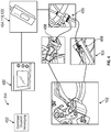
- Fig. 1 shows a line network 100 with a charging socket 102, a sealed connector 104 and a charging socket 102 and the sealed connector 104 connecting cable 106.
- the charging socket 102 is adapted to supply electrical energy to an energy storage device of a vehicle, not shown here.
- the cable 106 is fluid-tightly connected to the fluid-tight charging can 102 as specified.
- the cable 106 is fluid-tightly connected to the sealed connector 104 in accordance with the specification.
- the line network 100 is a test specimen 108, which is to be tested for leaks.
- a tightness tester 110 is further connected to the connector 104 of the line network 100.
- the tightness test device 110 includes a test adapter 112, a fluid supply 114 and a measuring device 116.
- the test adapter 112 contacts the plug connector 104. In this case, a fluid-tight connection between the two is produced.
- the fluid supply 114 is set up to provide a fluid 118 on the test adapter 112.
- the measuring device 116 is disposed between the fluid supply 114 and the test adapter 112.
- the fluid 118 provided by the fluid supply 114 is passed to the test adapter 112 via the measuring device 116.
- the measuring device 116 is configured to evaluate a tightness of the charging socket 102 based on an evaluation of physical quantities of the fluid 118 provided.
- the line network 100 is a high voltage line network.
- the cables 106 may have a silicone insulation.
- the leak tester 110 is configured to check the test piece 108 for leaks.
- the charging socket 102 is shown only schematically.
- the charging socket 102 has on the back a sealed space in which contacts and a printed circuit board is located. There is no direct way to pressurize the charging socket in the sealed area to perform a test.
- the charging socket 102 has no "feed point", via the compressed air could be fed and thus the tightness could be checked. Such an entry point also represents an additional possible source of error, since even this could be leaking, especially after a test run.
- a conventional pressure test on the contact side of the charging socket 102 does not ensure the entire tightness of the charging socket 102 and check securely, since seals built-in back would not be checked.
- the measuring device 116 comprises a flow sensor 120.
- the flow sensor 120 is set up to detect a flow rate of the fluid 118. Furthermore, the measuring device 116 is set up to determine the tightness using the flow rate. After a pressure build-up phase with a high flow rate, the flow rate settles to a value. The duration of the pressure build-up phase is also referred to as settling time. If this value is below a predefined threshold, the device under test 108 will be denoted as "tight" or "good".
- Fig. 2 shows one compared to in Fig. 1 illustrated second embodiment extended second embodiment of a tightness tester 110.
- the line network 100 has a second connector 204. Derfax Stecker 204 ist über niethacil Stecker 204 aufnote.
- the second connector 204 is connected to the charging socket 102 via two cables 206.
- the test adapter 112 is configured to contact both the first connector 104 and the second connector 204 in a fluid-tight manner.
- the concept is scalable. In a first variant of the test adapter 112 is formed, all connectors 104, 204 of a To contact line network 100. In a second variant, the test adapter 112 is configured to contact at least one first connector 104, the remaining connectors 204 of the conduit network 100 are sealed fluid-tight with caps, not shown.
- the fluid 118 is gaseous.
- the fluid may be air in a particular variant, the fluid has an increased proportion of helium or hydrogen, which is detectable with a gas sensor 230.
- the gas sensor 230 is arranged to sense an emission of the helium or hydrogen comprising fluid from the charging socket 102 and the line network 100 and to indicate a leakage accordingly. An indicated leakage contradicts the requirement for tightness. In this case, the test piece 108 would be sorted out.
- the measuring device 116 additionally comprises a visual sensor 232.
- the visual sensor 232 may be a camera 234, in particular for detecting color images. It is conceivable that the provided fluid 118 is colored and thus a leakage or leakage of the test piece 108 can be seen when a correspondingly colored fluid emerges. An evaluation of the color information (possibly even purely statistically based on a histogram) is sufficient to check the tightness.
- Fig. 3 extends the already described embodiments by additional contact elements 340 for electrically contacting the line network 100. If the line network 100 is a high-voltage line network, then the contact elements 340 are formed as high-voltage contact elements 342. In this case, the leakage tester 100 is extended by an additional electrical test device 344, which is set up to electrically test the test object 108 in parallel to the leak test.
- the entire line network 100 also referred to as a charge line set, forms an airtight network.
- the charging socket 102 can not be directly exposed to air to measure the tightness.
- the concept described here envisages subjecting the entire pipeline network to a leak test.
- the measuring device is for example in the in Fig. 4 illustrated embodiment, to draw conclusions on the tightness of the system on the determination of a flow value in l / min at an overpressure of 0.2 bar.
- the fluid 118 is supplied via a compressed air regulator 450.
- the fluid 118 is provided here as compressed air from a central compressed air supply 452.
- a commercially available pressure control valve is provided.
- the flow meter 454 thus constitutes a measuring device 116 comprising a flow sensor 120.
- the fluid 118 is routed to the flow meter 454 via a T-manifold 456 to two separate contact sockets 458.
- the T-manifold 456 and the two separate contact sockets 458 are part of the test adapter 112.
- the contact sockets 458 are configured to contact the connectors 104, 204 in a fluid-tight manner. In other words, the contact sockets 458 are installed for sealing in the test adapter 112.
- the contact sockets 458, also referred to as insert correspond in geometry in the sealing surface area to the inserts of test adapters 112 or corresponding mating connectors. About the contact sockets 458, the connectors 104, 204 are acted upon by compressed air, or the fluid 118. The thus-fed fluid 118 is guided into the charging socket 102 via the cables 106, 206, which are designed as high-voltage lines in the illustrated embodiment.
- the flow meter 454 has a measuring range of 0 ml / min to 999 ml / min.
- a further PE line may be provided, via which a small amount of the fluid 118 can escape.
- the flow rate may, for example, settle to a value of 30 ml / min.
- the threshold may be set at 100 ml / min at an overpressure of 0.2 bar.
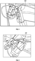
- Fig. 5 and Fig. 6 show variants of contact sockets 458 as part of a test adapter 112.
- the contact sockets 458 correspond in their geometry mating connectors to the connectors 104, 204 and establish a fluid-tight connection between the test adapter 112 and the connectors 104, 204, so that the fluid 118 in the line network 100th can be directed.
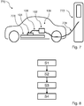
- Fig. 7 1 shows a vehicle 770 with a charging socket 102 at a charging station 772.
- the charging station 772 is connected to the charging socket 102 of the vehicle 770 via a charging cable 774.
- the charging cable 774 has a charging plug, not shown, at the end remote from the charging station 772 for contacting the charging socket 102.
- the charging socket 102 is part of a line network 102, as this example in Fig. 1 to Fig. 3 is described.
- a connector 104 is connected to an energy storage 776 of the vehicle 770.
- Fig. 7 a schematic view of a charging system, as it is used to charge an electrically powered vehicle, referred to as electric vehicle or BEV or PHEV.
- the charging socket 102 can also be referred to as a charging socket into which a mating plug in the form of a charging plug connected electrically to the charging station 772 can be inserted at the end of the charging cable 774.
- the charging cable 774 is electrically connected to the charging station, so that an electrical connection between the charging station 772 and the vehicle 770 can be made by a connection between the charging socket 102 and the charging plug, not shown, and charging currents for charging the energy storage 776 of the vehicle 770 can be transmitted ,
- Fig. 8 shows a flowchart of a method for testing a charging socket for supplying electrical energy to an energy storage of a vehicle with the steps contacting S1, providing S2, conduct S3 and detect S4.
- step S1 of contacting a sealed connector of a conduit network comprising the sealed connector, a charging socket for mounting to an at least partially electrically powered vehicle, and a cable connecting the connector and the charging socket are contacted.
- step S2 a fluid is provided to the connector, which is passed in step S3 of the conduction from the connector via the cable to the charging socket.
- step S4 of the detection a tightness of the charging socket or the wiring network is detected based on the provided fluid.
Landscapes
- Physics & Mathematics (AREA)
- General Physics & Mathematics (AREA)
- Engineering & Computer Science (AREA)
- Power Engineering (AREA)
- Transportation (AREA)
- Mechanical Engineering (AREA)
- Electric Propulsion And Braking For Vehicles (AREA)
- Examining Or Testing Airtightness (AREA)
Applications Claiming Priority (1)
| Application Number | Priority Date | Filing Date | Title |
|---|---|---|---|
| DE102017129061.3A DE102017129061B3 (de) | 2017-12-06 | 2017-12-06 | Vorrichtung und verfahren zum prüfen einer ladedose zum zuführen elektrischer energie zu einem energiespeicher eines fahrzeugs |
Publications (3)
| Publication Number | Publication Date |
|---|---|
| EP3495796A2 true EP3495796A2 (fr) | 2019-06-12 |
| EP3495796A3 EP3495796A3 (fr) | 2019-10-23 |
| EP3495796B1 EP3495796B1 (fr) | 2021-11-03 |
Family
ID=64606791
Family Applications (1)
| Application Number | Title | Priority Date | Filing Date |
|---|---|---|---|
| EP18210292.1A Active EP3495796B1 (fr) | 2017-12-06 | 2018-12-05 | Dispositif et procédé de vérification d'un adaptateur de charge pour fournir de l'énergie électrique à un stockage d'énergie d'un véhicule |
Country Status (4)
| Country | Link |
|---|---|
| US (1) | US10481038B2 (fr) |
| EP (1) | EP3495796B1 (fr) |
| CN (1) | CN109470977B (fr) |
| DE (1) | DE102017129061B3 (fr) |
Families Citing this family (11)
| Publication number | Priority date | Publication date | Assignee | Title |
|---|---|---|---|---|
| US10706519B2 (en) * | 2018-10-01 | 2020-07-07 | Deere & Company | Vehicle detection system and method |
| DE102019219220A1 (de) * | 2019-12-10 | 2021-06-10 | Robert Bosch Gmbh | Vorrichtung zur Durchführung einer Dichtigkeitsprüfung eines elektrischen Bauteils |
| US11799307B2 (en) * | 2021-09-15 | 2023-10-24 | GM Global Technology Operations LLC | Methods and mechanisms for monitoring charging port functionality |
| JP7838993B2 (ja) * | 2022-03-23 | 2026-04-01 | 株式会社東芝 | 圧着判定装置、圧着判定方法、圧着判定プログラム、ワイヤーハーネス加工装置、及びワイヤーハーネス加工方法 |
| US20240120689A1 (en) | 2022-10-06 | 2024-04-11 | Caterpillar Inc. | Receptacle connector and method of leak testing component using receptacle connector |
| DE102022130655A1 (de) * | 2022-11-21 | 2024-05-23 | Phoenix Contact E-Mobility Gmbh | Steckverbinder, anordnung mit einem steckverbinder, einer ladevorrichtung und mit einem ladekabel, sowie verfahren zum betrieb eines steckverbinders und/oder einer ladevorrichtung |
| CN117360316B (zh) * | 2023-09-08 | 2024-04-16 | 安徽能通新能源科技有限公司 | 一种充电桩在线鉴定与车桩监测装置及其控制方法 |
| DE102023212790B3 (de) | 2023-12-15 | 2025-03-20 | Leoni Bordnetz-Systeme Gmbh | Verfahren zum Prüfen eines Kabelsatzes sowie Prüfvorrichtung |
| CN118017282B (zh) * | 2024-04-09 | 2024-07-16 | 国网山东省电力公司临朐县供电公司 | 一种带线缆的供电连接器 |
| DE102024117512B3 (de) * | 2024-06-20 | 2025-10-09 | Lisa Dräxlmaier GmbH | Verbundbauteil mit einem elektrisch leitenden Basiselement sowie Verfahren zur Durchführung einer Dichtheitsprüfung mit dem Verbundbauteil |
| DE102024210326A1 (de) * | 2024-10-25 | 2026-04-30 | Leoni Bordnetz-Systeme Gmbh | Prüfsystem zur Prüfung von Kabelsätzen sowie Prüfmodul für ein solches Prüfsystem |
Family Cites Families (14)
| Publication number | Priority date | Publication date | Assignee | Title |
|---|---|---|---|---|
| JP2859822B2 (ja) * | 1994-11-14 | 1999-02-24 | 株式会社ミツバ | 電気装置の気密テスト用構造 |
| DE10356039A1 (de) | 2003-12-01 | 2005-06-30 | Alcatel | Einblasvorrichtung zur Überprüfung einer Kabelmuffe auf Dichtigkeit, eine Einblasvorrichtung aufweisende Kabelmuffe sowie Verfahren zur Überprüfung von Kabelmuffen auf deren Dichtigkeit |
| US7624623B2 (en) * | 2005-01-10 | 2009-12-01 | Mocon, Inc. | Instrument and method for detecting leaks in hermetically sealed packaging |
| US7358860B2 (en) * | 2005-03-31 | 2008-04-15 | American Air Liquide, Inc. | Method and apparatus to monitor and detect cryogenic liquefied gas leaks |
| EP2093043B2 (fr) * | 2008-02-22 | 2019-11-20 | Lm Glasfiber A/S | Procédé et appareil pour détecter une fuite dans un procédé VARTM |
| DE102011116721A1 (de) * | 2011-10-24 | 2013-04-25 | Langmatz Gmbh | Anordnung zum Prüfen elektrischer Parameter einer Stromtankstelle |
| JP5920168B2 (ja) * | 2012-10-19 | 2016-05-18 | 日立金属株式会社 | ケーブル状態監視装置 |
| CN103308261B (zh) | 2013-06-24 | 2016-04-13 | 欧托凯勃汽车线束(太仓)有限公司 | 一种车用高压线束密封性在线测试系统 |
| JP6299948B2 (ja) * | 2013-10-16 | 2018-03-28 | 三菱自動車工業株式会社 | 車両の充電口構造 |
| US9488629B2 (en) * | 2014-04-10 | 2016-11-08 | General Electric Company | Method for detecting coolant leaks in generators |
| KR101750482B1 (ko) * | 2015-01-21 | 2017-06-23 | 주식회사 엘지화학 | 전지팩의 기밀도 테스트 방법 |
| DE102015112346A1 (de) * | 2015-07-29 | 2017-02-02 | Dr. Ing. H.C. F. Porsche Aktiengesellschaft | Elektrische Verteileranordnung |
| DE102016100817A1 (de) | 2016-01-19 | 2017-07-20 | Phoenix Contact E-Mobility Gmbh | Gehäuseteil mit einer Prüfstelle zur Dichtigkeitsprüfung |
| CN106004450B (zh) * | 2016-05-20 | 2018-04-13 | 安徽江淮汽车集团股份有限公司 | 高压连接器及其检测电路、检测方法 |
-
2017
- 2017-12-06 DE DE102017129061.3A patent/DE102017129061B3/de not_active Expired - Fee Related
-
2018
- 2018-12-05 CN CN201811476678.1A patent/CN109470977B/zh active Active
- 2018-12-05 US US16/211,022 patent/US10481038B2/en active Active
- 2018-12-05 EP EP18210292.1A patent/EP3495796B1/fr active Active
Also Published As
| Publication number | Publication date |
|---|---|
| DE102017129061B3 (de) | 2019-01-31 |
| CN109470977A (zh) | 2019-03-15 |
| US10481038B2 (en) | 2019-11-19 |
| EP3495796A3 (fr) | 2019-10-23 |
| US20190170605A1 (en) | 2019-06-06 |
| EP3495796B1 (fr) | 2021-11-03 |
| CN109470977B (zh) | 2021-01-26 |
Similar Documents
| Publication | Publication Date | Title |
|---|---|---|
| DE102017129061B3 (de) | Vorrichtung und verfahren zum prüfen einer ladedose zum zuführen elektrischer energie zu einem energiespeicher eines fahrzeugs | |
| DE202017007157U1 (de) | Gehäuseteil mit einer Prüfstelle zur Dichtigkeitsprüfung | |
| DE102015226223A1 (de) | Vorrichtung und Verfahren zur Überprüfung eines Ladekabels | |
| DE19507959C1 (de) | Vorrichtung zur Strommessung an einer Hauptstromleitung eines Fahrzeug-Bordnetzes | |
| DE102014006654A1 (de) | Elektrische Leistungsschnittstelle eines Fahrzeugs | |
| EP3867653B1 (fr) | Système de charge avec un compteur électrique et un câble de charge | |
| DE102015008467A1 (de) | Vorrichtung und Verfahren zum Überprüfen einer Funktionsüberwachungseinrichtung eines Schaltschützes eines Kraftfahrzeugs | |
| DE102016107216A1 (de) | Vorrichtung und Verfahren zur Dichtheitsprüfung einer Komponente eines Kabelbaums für ein Fahrzeug | |
| DE102013013951B4 (de) | Messanordnung, Messgerät und Verfahren zur Bestimmung von Isolationsfehlern | |
| DE102011116721A1 (de) | Anordnung zum Prüfen elektrischer Parameter einer Stromtankstelle | |
| DE102013221590A1 (de) | Verfahren zur Überwachung der Gleichspannungsladung des Energiespeichers eines Kraftfahrzeugs sowie ein Batteriemanagementsystem | |
| DE102024125628A1 (de) | Ladezustandsüberwachungsvorrichtung und Verfahren | |
| DE202019104478U1 (de) | Hochvoltprüfadapter | |
| AT406091B (de) | Verfahren zur reparatur- und wiederholungsprüfung von elektrischen geräten sowie vorrichtung zur durchführung des verfahrens | |
| DE2322623C3 (de) | Anordnung zur Messung des Leistungsfaktors einer Ölprobe bzw. Verlustfaktors einer Ölprobe | |
| AT526973B1 (de) | Messvorrichtung für ein Hochvolt-System | |
| DE102010013103B4 (de) | Vorrichtung und Verfahren zur Diagnose von Messobjekten unter Verwendung einer Messspannung | |
| DE102024203779B3 (de) | Verfahren zur Dichtigkeitsprüfung an einem Kabel sowie Prüfvorrichtung hierfür | |
| DE102015100354A1 (de) | Signalleitungssystem und Verfahren zum Überwachen des Betriebszustands einer elektrochemischen Vorrichtung | |
| AT528113B1 (de) | Messung eines Isolationswiderstandes eines Bordnetzes eines Elektrofahrzeugs | |
| LU503454B1 (de) | Messgerät und Ladesystem zur eichrechtskonformen Messung von elektrischer Energie sowie Verfahren dazu | |
| DE102006021859B4 (de) | Steckverbinder mit Zuleitung | |
| DE102017204885A1 (de) | Isolationswächter | |
| DE102023103318A1 (de) | Verfahren zum Warten eines Hochvolt-Systems | |
| DE102013218716A1 (de) | Prüfeinrichtung für elektrische Komponenten |
Legal Events
| Date | Code | Title | Description |
|---|---|---|---|
| PUAI | Public reference made under article 153(3) epc to a published international application that has entered the european phase |
Free format text: ORIGINAL CODE: 0009012 |
|
| STAA | Information on the status of an ep patent application or granted ep patent |
Free format text: STATUS: THE APPLICATION HAS BEEN PUBLISHED |
|
| AK | Designated contracting states |
Kind code of ref document: A2 Designated state(s): AL AT BE BG CH CY CZ DE DK EE ES FI FR GB GR HR HU IE IS IT LI LT LU LV MC MK MT NL NO PL PT RO RS SE SI SK SM TR |
|
| AX | Request for extension of the european patent |
Extension state: BA ME |
|
| PUAL | Search report despatched |
Free format text: ORIGINAL CODE: 0009013 |
|
| AK | Designated contracting states |
Kind code of ref document: A3 Designated state(s): AL AT BE BG CH CY CZ DE DK EE ES FI FR GB GR HR HU IE IS IT LI LT LU LV MC MK MT NL NO PL PT RO RS SE SI SK SM TR |
|
| AX | Request for extension of the european patent |
Extension state: BA ME |
|
| RIC1 | Information provided on ipc code assigned before grant |
Ipc: G01M 3/22 20060101ALI20190918BHEP Ipc: G01M 3/04 20060101ALI20190918BHEP Ipc: G01M 3/26 20060101ALI20190918BHEP Ipc: G01M 3/32 20060101AFI20190918BHEP Ipc: H01R 13/52 20060101ALI20190918BHEP Ipc: B60L 53/16 20190101ALI20190918BHEP Ipc: G01R 31/04 20060101ALI20190918BHEP Ipc: G01M 3/38 20060101ALI20190918BHEP |
|
| STAA | Information on the status of an ep patent application or granted ep patent |
Free format text: STATUS: REQUEST FOR EXAMINATION WAS MADE |
|
| 17P | Request for examination filed |
Effective date: 20200325 |
|
| RBV | Designated contracting states (corrected) |
Designated state(s): AL AT BE BG CH CY CZ DE DK EE ES FI FR GB GR HR HU IE IS IT LI LT LU LV MC MK MT NL NO PL PT RO RS SE SI SK SM TR |
|
| STAA | Information on the status of an ep patent application or granted ep patent |
Free format text: STATUS: EXAMINATION IS IN PROGRESS |
|
| 17Q | First examination report despatched |
Effective date: 20200730 |
|
| REG | Reference to a national code |
Ref country code: DE Ref legal event code: R079 Ref document number: 502018007671 Country of ref document: DE Free format text: PREVIOUS MAIN CLASS: G01M0003320000 Ipc: G01R0031010000 |
|
| RIC1 | Information provided on ipc code assigned before grant |
Ipc: G01R 31/01 20200101AFI20210407BHEP |
|
| GRAP | Despatch of communication of intention to grant a patent |
Free format text: ORIGINAL CODE: EPIDOSNIGR1 |
|
| STAA | Information on the status of an ep patent application or granted ep patent |
Free format text: STATUS: GRANT OF PATENT IS INTENDED |
|
| INTG | Intention to grant announced |
Effective date: 20210623 |
|
| GRAS | Grant fee paid |
Free format text: ORIGINAL CODE: EPIDOSNIGR3 |
|
| GRAA | (expected) grant |
Free format text: ORIGINAL CODE: 0009210 |
|
| STAA | Information on the status of an ep patent application or granted ep patent |
Free format text: STATUS: THE PATENT HAS BEEN GRANTED |
|
| AK | Designated contracting states |
Kind code of ref document: B1 Designated state(s): AL AT BE BG CH CY CZ DE DK EE ES FI FR GB GR HR HU IE IS IT LI LT LU LV MC MK MT NL NO PL PT RO RS SE SI SK SM TR |
|
| REG | Reference to a national code |
Ref country code: GB Ref legal event code: FG4D Free format text: NOT ENGLISH |
|
| REG | Reference to a national code |
Ref country code: AT Ref legal event code: REF Ref document number: 1444435 Country of ref document: AT Kind code of ref document: T Effective date: 20211115 Ref country code: CH Ref legal event code: EP |
|
| REG | Reference to a national code |
Ref country code: IE Ref legal event code: FG4D Free format text: LANGUAGE OF EP DOCUMENT: GERMAN |
|
| REG | Reference to a national code |
Ref country code: DE Ref legal event code: R096 Ref document number: 502018007671 Country of ref document: DE |
|
| REG | Reference to a national code |
Ref country code: LT Ref legal event code: MG9D |
|
| REG | Reference to a national code |
Ref country code: NL Ref legal event code: MP Effective date: 20211103 |
|
| PG25 | Lapsed in a contracting state [announced via postgrant information from national office to epo] |
Ref country code: RS Free format text: LAPSE BECAUSE OF FAILURE TO SUBMIT A TRANSLATION OF THE DESCRIPTION OR TO PAY THE FEE WITHIN THE PRESCRIBED TIME-LIMIT Effective date: 20211103 Ref country code: LT Free format text: LAPSE BECAUSE OF FAILURE TO SUBMIT A TRANSLATION OF THE DESCRIPTION OR TO PAY THE FEE WITHIN THE PRESCRIBED TIME-LIMIT Effective date: 20211103 Ref country code: FI Free format text: LAPSE BECAUSE OF FAILURE TO SUBMIT A TRANSLATION OF THE DESCRIPTION OR TO PAY THE FEE WITHIN THE PRESCRIBED TIME-LIMIT Effective date: 20211103 Ref country code: BG Free format text: LAPSE BECAUSE OF FAILURE TO SUBMIT A TRANSLATION OF THE DESCRIPTION OR TO PAY THE FEE WITHIN THE PRESCRIBED TIME-LIMIT Effective date: 20220203 |
|
| PG25 | Lapsed in a contracting state [announced via postgrant information from national office to epo] |
Ref country code: IS Free format text: LAPSE BECAUSE OF FAILURE TO SUBMIT A TRANSLATION OF THE DESCRIPTION OR TO PAY THE FEE WITHIN THE PRESCRIBED TIME-LIMIT Effective date: 20220303 Ref country code: SE Free format text: LAPSE BECAUSE OF FAILURE TO SUBMIT A TRANSLATION OF THE DESCRIPTION OR TO PAY THE FEE WITHIN THE PRESCRIBED TIME-LIMIT Effective date: 20211103 Ref country code: PT Free format text: LAPSE BECAUSE OF FAILURE TO SUBMIT A TRANSLATION OF THE DESCRIPTION OR TO PAY THE FEE WITHIN THE PRESCRIBED TIME-LIMIT Effective date: 20220303 Ref country code: PL Free format text: LAPSE BECAUSE OF FAILURE TO SUBMIT A TRANSLATION OF THE DESCRIPTION OR TO PAY THE FEE WITHIN THE PRESCRIBED TIME-LIMIT Effective date: 20211103 Ref country code: NO Free format text: LAPSE BECAUSE OF FAILURE TO SUBMIT A TRANSLATION OF THE DESCRIPTION OR TO PAY THE FEE WITHIN THE PRESCRIBED TIME-LIMIT Effective date: 20220203 Ref country code: NL Free format text: LAPSE BECAUSE OF FAILURE TO SUBMIT A TRANSLATION OF THE DESCRIPTION OR TO PAY THE FEE WITHIN THE PRESCRIBED TIME-LIMIT Effective date: 20211103 Ref country code: LV Free format text: LAPSE BECAUSE OF FAILURE TO SUBMIT A TRANSLATION OF THE DESCRIPTION OR TO PAY THE FEE WITHIN THE PRESCRIBED TIME-LIMIT Effective date: 20211103 Ref country code: HR Free format text: LAPSE BECAUSE OF FAILURE TO SUBMIT A TRANSLATION OF THE DESCRIPTION OR TO PAY THE FEE WITHIN THE PRESCRIBED TIME-LIMIT Effective date: 20211103 Ref country code: GR Free format text: LAPSE BECAUSE OF FAILURE TO SUBMIT A TRANSLATION OF THE DESCRIPTION OR TO PAY THE FEE WITHIN THE PRESCRIBED TIME-LIMIT Effective date: 20220204 Ref country code: ES Free format text: LAPSE BECAUSE OF FAILURE TO SUBMIT A TRANSLATION OF THE DESCRIPTION OR TO PAY THE FEE WITHIN THE PRESCRIBED TIME-LIMIT Effective date: 20211103 |
|
| PG25 | Lapsed in a contracting state [announced via postgrant information from national office to epo] |
Ref country code: SM Free format text: LAPSE BECAUSE OF FAILURE TO SUBMIT A TRANSLATION OF THE DESCRIPTION OR TO PAY THE FEE WITHIN THE PRESCRIBED TIME-LIMIT Effective date: 20211103 Ref country code: SK Free format text: LAPSE BECAUSE OF FAILURE TO SUBMIT A TRANSLATION OF THE DESCRIPTION OR TO PAY THE FEE WITHIN THE PRESCRIBED TIME-LIMIT Effective date: 20211103 Ref country code: RO Free format text: LAPSE BECAUSE OF FAILURE TO SUBMIT A TRANSLATION OF THE DESCRIPTION OR TO PAY THE FEE WITHIN THE PRESCRIBED TIME-LIMIT Effective date: 20211103 Ref country code: EE Free format text: LAPSE BECAUSE OF FAILURE TO SUBMIT A TRANSLATION OF THE DESCRIPTION OR TO PAY THE FEE WITHIN THE PRESCRIBED TIME-LIMIT Effective date: 20211103 Ref country code: DK Free format text: LAPSE BECAUSE OF FAILURE TO SUBMIT A TRANSLATION OF THE DESCRIPTION OR TO PAY THE FEE WITHIN THE PRESCRIBED TIME-LIMIT Effective date: 20211103 Ref country code: CZ Free format text: LAPSE BECAUSE OF FAILURE TO SUBMIT A TRANSLATION OF THE DESCRIPTION OR TO PAY THE FEE WITHIN THE PRESCRIBED TIME-LIMIT Effective date: 20211103 |
|
| REG | Reference to a national code |
Ref country code: CH Ref legal event code: PL |
|
| REG | Reference to a national code |
Ref country code: DE Ref legal event code: R097 Ref document number: 502018007671 Country of ref document: DE |
|
| PG25 | Lapsed in a contracting state [announced via postgrant information from national office to epo] |
Ref country code: MC Free format text: LAPSE BECAUSE OF FAILURE TO SUBMIT A TRANSLATION OF THE DESCRIPTION OR TO PAY THE FEE WITHIN THE PRESCRIBED TIME-LIMIT Effective date: 20211103 |
|
| PLBE | No opposition filed within time limit |
Free format text: ORIGINAL CODE: 0009261 |
|
| STAA | Information on the status of an ep patent application or granted ep patent |
Free format text: STATUS: NO OPPOSITION FILED WITHIN TIME LIMIT |
|
| REG | Reference to a national code |
Ref country code: BE Ref legal event code: MM Effective date: 20211231 |
|
| 26N | No opposition filed |
Effective date: 20220804 |
|
| PG25 | Lapsed in a contracting state [announced via postgrant information from national office to epo] |
Ref country code: LU Free format text: LAPSE BECAUSE OF NON-PAYMENT OF DUE FEES Effective date: 20211205 Ref country code: IE Free format text: LAPSE BECAUSE OF NON-PAYMENT OF DUE FEES Effective date: 20211205 Ref country code: AL Free format text: LAPSE BECAUSE OF FAILURE TO SUBMIT A TRANSLATION OF THE DESCRIPTION OR TO PAY THE FEE WITHIN THE PRESCRIBED TIME-LIMIT Effective date: 20211103 |
|
| PG25 | Lapsed in a contracting state [announced via postgrant information from national office to epo] |
Ref country code: SI Free format text: LAPSE BECAUSE OF FAILURE TO SUBMIT A TRANSLATION OF THE DESCRIPTION OR TO PAY THE FEE WITHIN THE PRESCRIBED TIME-LIMIT Effective date: 20211103 Ref country code: BE Free format text: LAPSE BECAUSE OF NON-PAYMENT OF DUE FEES Effective date: 20211231 |
|
| PG25 | Lapsed in a contracting state [announced via postgrant information from national office to epo] |
Ref country code: LI Free format text: LAPSE BECAUSE OF NON-PAYMENT OF DUE FEES Effective date: 20211231 Ref country code: CH Free format text: LAPSE BECAUSE OF NON-PAYMENT OF DUE FEES Effective date: 20211231 |
|
| PG25 | Lapsed in a contracting state [announced via postgrant information from national office to epo] |
Ref country code: CY Free format text: LAPSE BECAUSE OF FAILURE TO SUBMIT A TRANSLATION OF THE DESCRIPTION OR TO PAY THE FEE WITHIN THE PRESCRIBED TIME-LIMIT Effective date: 20211103 |
|
| PG25 | Lapsed in a contracting state [announced via postgrant information from national office to epo] |
Ref country code: HU Free format text: LAPSE BECAUSE OF FAILURE TO SUBMIT A TRANSLATION OF THE DESCRIPTION OR TO PAY THE FEE WITHIN THE PRESCRIBED TIME-LIMIT; INVALID AB INITIO Effective date: 20181205 |
|
| P01 | Opt-out of the competence of the unified patent court (upc) registered |
Effective date: 20231017 |
|
| PG25 | Lapsed in a contracting state [announced via postgrant information from national office to epo] |
Ref country code: MK Free format text: LAPSE BECAUSE OF FAILURE TO SUBMIT A TRANSLATION OF THE DESCRIPTION OR TO PAY THE FEE WITHIN THE PRESCRIBED TIME-LIMIT Effective date: 20211103 |
|
| PG25 | Lapsed in a contracting state [announced via postgrant information from national office to epo] |
Ref country code: MT Free format text: LAPSE BECAUSE OF FAILURE TO SUBMIT A TRANSLATION OF THE DESCRIPTION OR TO PAY THE FEE WITHIN THE PRESCRIBED TIME-LIMIT Effective date: 20211103 |
|
| REG | Reference to a national code |
Ref country code: AT Ref legal event code: MM01 Ref document number: 1444435 Country of ref document: AT Kind code of ref document: T Effective date: 20231205 |
|
| PG25 | Lapsed in a contracting state [announced via postgrant information from national office to epo] |
Ref country code: AT Free format text: LAPSE BECAUSE OF NON-PAYMENT OF DUE FEES Effective date: 20231205 |
|
| PGFP | Annual fee paid to national office [announced via postgrant information from national office to epo] |
Ref country code: FR Payment date: 20250930 Year of fee payment: 8 |
|
| PG25 | Lapsed in a contracting state [announced via postgrant information from national office to epo] |
Ref country code: TR Free format text: LAPSE BECAUSE OF FAILURE TO SUBMIT A TRANSLATION OF THE DESCRIPTION OR TO PAY THE FEE WITHIN THE PRESCRIBED TIME-LIMIT Effective date: 20211103 |
|
| PGFP | Annual fee paid to national office [announced via postgrant information from national office to epo] |
Ref country code: GB Payment date: 20251001 Year of fee payment: 8 |
|
| PGFP | Annual fee paid to national office [announced via postgrant information from national office to epo] |
Ref country code: IT Payment date: 20251121 Year of fee payment: 8 |
|
| PGFP | Annual fee paid to national office [announced via postgrant information from national office to epo] |
Ref country code: DE Payment date: 20260226 Year of fee payment: 8 |
|
| PGFP | Annual fee paid to national office [announced via postgrant information from national office to epo] |
Ref country code: AT Payment date: 20260410 Year of fee payment: 5 |