EP3496219B1 - Boîtier de connexion - Google Patents
Boîtier de connexion Download PDFInfo
- Publication number
- EP3496219B1 EP3496219B1 EP17205887.7A EP17205887A EP3496219B1 EP 3496219 B1 EP3496219 B1 EP 3496219B1 EP 17205887 A EP17205887 A EP 17205887A EP 3496219 B1 EP3496219 B1 EP 3496219B1
- Authority
- EP
- European Patent Office
- Prior art keywords
- mounting box
- lead
- planar surface
- connection casing
- surface section
- Prior art date
- Legal status (The legal status is an assumption and is not a legal conclusion. Google has not performed a legal analysis and makes no representation as to the accuracy of the status listed.)
- Active
Links
Images


Classifications
-
- H—ELECTRICITY
- H02—GENERATION; CONVERSION OR DISTRIBUTION OF ELECTRIC POWER
- H02G—INSTALLATION OF ELECTRIC CABLES OR LINES, OR OF COMBINED OPTICAL AND ELECTRIC CABLES OR LINES
- H02G3/00—Installations of electric cables or lines or protective tubing therefor in or on buildings, equivalent structures or vehicles
- H02G3/02—Details
- H02G3/08—Distribution boxes; Connection or junction boxes
- H02G3/081—Bases, casings or covers
- H02G3/083—Inlets
- H02G3/085—Inlets including knock-out or tear-out sections
-
- H—ELECTRICITY
- H02—GENERATION; CONVERSION OR DISTRIBUTION OF ELECTRIC POWER
- H02G—INSTALLATION OF ELECTRIC CABLES OR LINES, OR OF COMBINED OPTICAL AND ELECTRIC CABLES OR LINES
- H02G3/00—Installations of electric cables or lines or protective tubing therefor in or on buildings, equivalent structures or vehicles
- H02G3/02—Details
- H02G3/06—Joints for connecting lengths of protective tubing or channels, to each other or to casings, e.g. to distribution boxes; Ensuring electrical continuity in the joint
- H02G3/0616—Joints for connecting tubing to casing
- H02G3/0691—Fixing tubing to casing by auxiliary means co-operating with indentations of the tubing, e.g. with tubing-convolutions
-
- H—ELECTRICITY
- H02—GENERATION; CONVERSION OR DISTRIBUTION OF ELECTRIC POWER
- H02G—INSTALLATION OF ELECTRIC CABLES OR LINES, OR OF COMBINED OPTICAL AND ELECTRIC CABLES OR LINES
- H02G3/00—Installations of electric cables or lines or protective tubing therefor in or on buildings, equivalent structures or vehicles
- H02G3/02—Details
- H02G3/08—Distribution boxes; Connection or junction boxes
- H02G3/12—Distribution boxes; Connection or junction boxes for flush mounting
Definitions
- the present invention relates to a connection casing.
- connection casing could be formed of a mounting box or of a connection sleeve.
- Mounting boxes may be divided into two basic types.
- the first type of mounting box is attached to the wall construction before the inner wall is erected, whereby also the cables and/or the tubes with electric wires are connected to the mounting box before the inner wall is erected.
- the inner wall is then erected, whereby an opening is formed in the inner wall for an adjustment collar of the mounting box.
- the adjustment collar will protrude through the opening in the inner wall so that the planar outer surface of the adjustment collar is flush with the inner surface of the inner wall. Access to the mounting space provided within the mounting box is thus provided through the adjustment collar.
- the second type of mounting box is attached to the wall construction after the inner wall has been erected.
- An opening is formed in the inner wall, the cables and/or tubes are connected to the mounting box through the opening, and the mounting box is then pushed through the opening until the flanges of the mounting box seat against the inner wall. Fastening means will then secure the mounting box to the wall construction.
- Both types of mounting boxes are provided with cable and/or tube lead-ins in a bottom portion of the mounting box.
- the cable lead-ins must be provided with strain relief preventing the cable from accidently slipping out of the cable lead-in when a dragging force is acting on the cable.
- the tube lead-ins need not be provided with strain relief.
- the tube lead-ins may be formed as a simple opening in the mounting box when flexible corrugated tubes are used. The valleys in the corrugation will seat into the edges of the opening forming a sort of a locking for the tube.
- Each lead-in must thus be formed either as a cable lead-in with strain relief or as a tube lead-in without strain relief.
- connection sleeve may be used to connect two tubes or to lead a cable into a tube.
- One end of the connection sleeve may in the latter case comprise a lead in provided with strain relief.
- a tube is connected to the other opposite end of the connection sleeve. The cable may thus be pushed through the lead in and further through the tube connected to the other end of the connection sleeve.
- the box comprises a cover, a front opening, a base with prepared regions for cable guiding.
- Each cable guiding comprises a cap and at least one ring tapering outwards in one piece and defining cutting surfaces guiding a cutting tool and freeing a hole by separation along the cutting surfaces.
- EP 1 489 713 discloses a wall penetration device for cables or conduits, in particular for flexible electric cables.
- the device is designed to be mounted in a sealed manner in a circular opening of the wall.
- the wall may be an envelope of an electrical equipment, such as a cabinet, or a junction box or a branch.
- the device consists of a circular plug provided with an annular clamping groove on the outer perimeter of the plug. The edge of the opening in the wall will be seated in the groove so that the plug becomes attached to the opening.
- a planar surface in the plug is provided with sealing ribs acting on the outer wall face for sealing the plug to the wall.
- the interior of the plug comprises a passageway for a cable. Lips protrude into the passageway in order to be pressed elastically against cables of different diameters.
- the lips are of a generally frustoconical shape and form part of concentric breakable slices.
- EP 2 822 119 discloses a mounting box.
- the mounting box comprises a box case having at least one installation aperture and attachment means comprising at least one attachment member for each of the at least one installation aperture.
- Each attachment member has an access surface and a stopping surface.
- the attachment means is adapted to allow movement of an elongated electric installation member through an installation aperture towards the mounting space and to resist reverse movement of the elongated electric installation member.
- Each attachment member is an integral part of the box case such that the box case and each attachment member are made from the same material.
- An object of the present invention is to achieve a connection casing that can easily be adapted according to different installation requirements.
- connection casing according to the invention is defined in claim 1.
- connection casing provided with combined lead-ins that can be used as cable lead-ins with strain relief and as tube lead-ins without strain relief makes the connection casing more universal.
- the amount of cable lead-ins and tube lead-ins in the connection casing can be decided case by case when the connection casing is to be installed. The technician can easily during the installation of the connection casing cut off lead-in elements from the connection casing with a knife in order to turn a cable lead-in provided with strain relief into a tube lead-in without strain relief if this is needed.
- the cutting off of the lead-in element may be done with a knife along a planar surface in the connection casing, whereby a clean and precise cut is achieved.
- the opening thus formed in the connection casing will be adapted to the dimensions of the corrugated tube to be used.
- the cross section of the opening may e.g. be round or oval corresponding to the cross section of the tube. Round and oval are normally used shapes in the tubes.
- the cross section of the tube and thereby also the cross section of the opening may have any form e.g. round, oval, rectangular, polygonal, trapeze like etc.
- a mounting box 400 according to the invention may be formed of a bottom part 10 and a top part 20.
- the bottom part 10 may be mounted into the top part 20 so that the bottom part 10 and the top part 20 may be adjusted in relation to each other.
- the mounting box 400 forms a connection casing.
- Figure 1 shows a bottom part of a mounting box according to the invention.
- the bottom part 10 may comprise a bottom portion 11 and a connection portion 12.
- the bottom part 10 may further comprise a longitudinal centre axis X-X.
- the bottom portion 11 of the bottom part 10 may comprise at least one planar surface section 11B being provided with at least one cable and/or tube lead-in 18C, 18D. Cables and/or tubes may be pushed through these lead-ins 18C, 18D.
- the lead-ins 18C, 18D provide a passage for electric wires positioned in tubes or in cables to pass into an interior of the mounting box 400 from an exterior of the mounting box 400.
- the lead-ins 18C, 18D may be closed with shield covers and opened during installation of the mounting box 400 by punching out the shield covers from the lead-ins 18C, 18D.
- the shield covers may be formed e.g.
- the lead-ins 18C, 18D may on the other hand be formed of crosswise running slots forming radially inwardly from the outer perimeter of the lead-in extending tongues.
- the tongues may terminate at a distance from the middle of the lead-in 18C, 18D.
- a cable may be pushed through the lead-in 18C, 18D whereby the tongues bend inwards and let the cable pass through.
- the tongues will on the other hand prevent withdrawal of the cable from the lead-in 18C, 18D once it has been pushed through.
- the tongues form thus a strain relief for the cable.
- the planar surface section 11B may be perpendicular or inclined in relation to the longitudinal centre axis X-X of the mounting box 400.
- connection portion 12 of the bottom part 10 may extend axially X-X outwards from a perimeter of the bottom portion 11 of the bottom part 10.
- the connection portion 12 may be formed of two diametrically opposite first connection sections 13A, 13B and two diametrically opposite second connection portions 14A, 14B positioned between the first connection sections 13A, 13B.
- the axial X-X length of the first connection sections 13A, 13B may be greater than the axial length of the second connection sections 14A, 14B.
- the first connection sections 13A, 13B and the second connection sections 14A, 14B form a substantially annular connection portion 12 of the bottom part 10.
- Each of the first connection sections 13A, 13B may comprise a first slot 15A, 15B.
- the first slot 15A, 15B may have a substantially rectangular shape.
- Each of the first slots 15A, 15B may extend axially X-X from an outer edge of the first connection section 13A, 13B towards the bottom portion 11. Both axial X-X edges of each of the first slots 15A, 15B may be provided with axial X-X grooves 16.
- the first slots 15A, 15B may be positioned on the middle of the perimeter of the first connection sections 13A, 13B.
- Each of the second connection sections 14A, 14B may be provided with axially X-X extending U-shaped guide members 17A, 17B. A portion of the guide members 17A, 17B may protrude radially outwards from the perimeter of the second connection sections 14A, 14B.
- each of the first connection sections 13A, 13B may be formed of a curved line.
- each of the second connection sections 14A, 14B may be formed by a straight line.
- the second connection sections 14A, 14B may further comprise first connection means 50, which will be described more in detail in connection with figure 5 .
- the perimeter of the cross section of the connection portion 12 of the bottom part 10 may be curved at the first connection sections 13A, 13B, straight at the second connection sections 14A, 14B and broken at the first slots 15A, 15B.
- Figure 2 shows a top part of the mounting box.
- the top part 20 may have a longitudinal centre axis X-X and may be composed of a body portion 21.
- the body portion 21 may have a closed outer perimeter.
- the body portion 21 may have an annular form.
- the body portion 21 may have a first end 21A forming an outer end of the mounting box 400.
- the first end 21A may be provided with radially outwardly from the first end 21A of the body portion 21 extending flange means 22.
- the flange means 22 may comprise four radially outwardly extending flange members 22 distributed at an equal angular distance from each other along the perimeter of the body portion 21 of the top part 20.
- the flange members 22 may define a flange plane.
- the first end 21A of the body portion 21 of the top part 20 forms a planar surface.
- the body portion 21 of the top part 20 may be formed of two diametrically opposite first support sections 23A, 23B and two diametrically opposite second support sections 24A, 24B positioned between the first support portions 23A, 23B.
- the axial X-X length of the first support sections 23A, 23B may be greater than the axial length of the second support sections 24A, 24B.
- the first support sections 23A, 23B and the second support sections 24A, 24B form a substantially annular body portion 21 of the top part 20.
- Each of the second support sections 23A, 23B may comprise a screw tower 25A, 25B extending axially X-X inwardly from the top end 21A of the body portion 21.
- Each opposite axial X-X edge of the screw tower 25A, 25B may be provided with an axial guide protrusion 26.
- the guide protrusions 26 may be received by the corresponding axial X-X grooves 16 in the first slots 15A, 15B in the bottom part 10 of the mounting box 400.
- Each of the screw towers 25A, 25B may have a substantially rectangular form.
- the screw towers 25A, 25B may be positioned in the centre of the perimeter of the first support sections 23A, 23B.
- the screw towers 25A, 25B may protrude inwards from the outer perimeter of the first support sections 23A, 23B.
- each of the screw towers 25A, 25B may be flush with a flange surface formed by the flange members 22 and may comprise an opening 210 for a fastening screw extending to the lower portion of the screw tower 25A, 25B and recesses 240 for fastening screws of the equipment that is to be accommodated in the mounting box 400.
- Each of the screw towers 25A, 25B may have an axial X-X length L3, which may be greater than the axial X-X length L4 of the first support sections 23A, 23B.
- each of the first support sections 23A, 23B may be formed of a curved line.
- each of the second support sections 24A, 24B may be formed by a straight line.
- each of the second support sections 24A, 24B may comprise second slots 27A, 27B extending axially X-X upwards from the lower edge of the second support sections 24A, 24B.
- the second slots 27A, 27B in the top part 20 may receive the guide members 17A, 17B in the bottom part 10.
- Each of the second support sections 24A, 24B may further comprise second connection means 60, which will be described more in detail in connection with figure 5 .
- the second connections means 60 in the top part 20 may cooperate with the first connection means 50 in the bottom part 10.
- the top part 20 may be enclosed by a circle.
- the perimeter of the top part 20 may have curved portions at the first support sections 23A, 23B and straight portions at the second support sections 24A, 24B.
- the middle portion of each second support section 24A, 24B accommodating the screw towers 25A, 25B may be straight.
- the straight second support sections 24A, 24B make it possible to connect several mounting boxes 400 together from any of these straight portions.
- Figure 3 shows a first view of the mounting box and figure 4 shows a second view of the mounting box.
- the mounting box 400 has a longitudinal centre axis X-X coinciding with the longitudinal centre axes X-X of the bottom part 10 and with the longitudinal centre axis X-X of the top part 20 of the mounting box 400.
- the position of the bottom part 10 and the top part 20 in relation to each other is adjustable along the longitudinal centre axis X-X.
- the figure shows a situation in which the bottom part 10 is fully pushed into the top part 20.
- the length L1 of the mounting box 400 is at a minimum in this situation.
- the connection space in the interior of the mounting box 400 is at a minimum when the bottom part 10 is fully pushed into the top part 20.
- the mounting box 400 comprises thus a body 10, 20 with a substantially closed outer perimeter, an open O1 top end 21A and a substantially closed bottom 10, a connection space M1 being formed within the mounting box 400.
- the body 10, 20 of the mounting box 400 may have a substantially tubular or a substantially annular form.
- a transverse cross section of the body 10, 20 of the mounting box 400 may be substantially round or substantially annular or substantially polygonal or any combination of two or more of these. There may further be substantially straight portions and/or curved portions in the transverse cross section of the body 10, 20 of the mounting box 400.
- the bottom part 10 may be drawn out a certain amount in the axial direction X-X from the top part 20.
- the mounting box 400 reaches a maximum length when the bottom part 10 is fully drawn out from the top part 20.
- the connection space M1 in the interior of the mounting box 400 is at a maximum when the bottom part 10 is fully withdrawn from the top part 20.
- the screw towers 25A, 25B of the top part 20 glide into the first slots 15A, 15B of the bottom part 10 when the bottom part 10 is pushed into the top part 20.
- the guide protrusions 26 at the edges of the screw towers 25A, 25B in the top part 20 glide in the grooves 16 at the axial X-X edges of the first slots 15A, 15B in the bottom part 10.
- the guide members 17A, 17B in the bottom part 10 glide into the corresponding second slots 27A, 27B in the top part 20.
- the second connection sections 14A, 14B of the bottom part 10 comprises first connection means 50 being positioned at both sides of the guide elements 17A, 17B ( Figure 1 ).
- the top part 20 comprises second opposite connection means 60 being positioned on the second support portions 24A, 24B of the top part 20 ( Figure 2 ).
- the bottom part 10 and the top part 20 are connected to each other through the first connection means 50 and the second connection means 60 so that an axial X-X length of the mounting box 400 can be varied between a maximum axial X-X length and a minimum axial X-X length by varying the axial X-X position of the second part 20 in relation to the first part 10 or vice a versa.
- radial protrusions 21C may grip into the edges of the opening into which the mounting box 400 is pushed eliminating rotation of the mounting box 400 in the opening.
- the interior of the mounting box 400 forms a space M1.
- the space M1 in the interior of the mounting box 400 is intended for accommodating cables and/or tubes as well as an electrical component such as a wall socket or a light switch.
- the wires of cables and/or tubes are connected in the lower portion of the space M1.
- the electrical component extends only into an upper portion of the space M1.
- the space M1 may be called a mounting space.
- the cross section of the opening O1 may have the form of a circle, an oval, a trapeze, a rectangle or any combination of these etc.
- the figure shows also fastening means 220, 230 cooperating with the flange means 22 in order to fasten the mounting box 400 to a wall.
- the fastening means 220, 230 comprises a fastening screw 220 and a fastening member 230.
- the fastening screw 220 passes through the opening 210 in the first end of the screw tower 25A, 25B to the fastening member 230 located in the lower portion of the screw tower 25A, 25B.
- the fastening screw 220 is turned clockwise with a screw driver, whereby the fastening member 230 is turned radially outwardly until the side surface of the fastening member 230 seats against and edge of the screw tower 25A, 25B.
- the fastening member 230 will then start moving towards the upper edge of the screw tower 25A, 25B when the fastening screw 220 is turned further clockwise.
- the fastening member 230 will then finally seat against the inner surface of the wall and the flange members 22 will seat against the outer surface of the wall when the mounting box is secured to the wall.
- the figure shows also the screws 250 for the fastening of the electrical component to be accommodated in the mounting box 400.
- the bottom part 10 of the mounting box 400 may comprise three planar surface sections 11A, 11B, 11C and each planar surface section may be provided with two lead-ins.
- the first planar surface section 11A may be perpendicular to the longitudinal centre axis X-X of the mounting box 400, whereby the first planar surface section 11A may form a bottom of the bottom part 10.
- the first planar surface section 11A may be provided with two lead-ins 18A, 18B.
- the second planar surface section 11B may be inclined in view of the longitudinal centre axis X-X of the mounting box 400, whereby the second planar surface section 11B may form a first planar side surface in the bottom part 10.
- the second planar surface section 11B may also be provided with two lead-ins 18C, 18D.
- the third planar surface section 11C may also be inclined in view of the longitudinal centre axis X-X of the mounting box 400, whereby the third planar surface section 11C may form a second planar side surface in the bottom part 10.
- the third planar surface section 11C may also be provided with two lead-ins, which are not seen in the figure.
- the second planar surface section 11B and the third planar surface section 11C are opposite to each other and may form mirror images to each other.
- One of the cable lead-ins 18C in the second planar surface section 11B in the bottom part 10 is provided with a lead-in element 100 protruding outwards from the second planar surface section 11B.
- the lead-in element 100 may be cut off from the second planar surface section 11B with a knife in order to form a tube lead-in.
- planar surface sections 11A, 11B, 11C may vary. Each planar surface section 11A, 11B, 11C may be formed only just around the edges of the at least one lead-in 18A, 18B, 18C, 18D on the respective planar surface 11A, 11B, 11C. The other possibility is that the planar surface section 11A, 11B, 11C is greater so that it extends a bit beyond the edges of the at least one lead-in 18A, 18B, 18C, 18D as is the embodiment shown in the figure.
- the figures show an embodiment in which the area of the first planar surface section 11A is bigger than the area of the second 11B and the third 11C planar surface section.
- the area of the second 11B and the third 11C planar surface section is equal in the figures.
- the arrangement of the planar surface sections 11A, 11B, 11C shown in the figures makes it possible to maximize the connection space M1 within the mounting box 400.
- the inclined planar side surface sections 11B, 11C makes it possible to fairly easy mount the tubes or cables to the lead-ins 18C, 18D before the mounting box 400 is pushed into the opening in the wall when the mounting box is mounted to the wall.
- Figure 5 shows a cross section of the mounting box.
- the cross section shows all three planar surface sections 11A, 11B, 11C in the bottom portion 11 of the bottom part 10 of the mounting box 400.
- the cross section shows also the first connection means 50 in the bottom part 10 and the second connection means 60 in the top part 20 of the mounting box 400.
- the axial length L1 of the mounting box is at the minimum value L1 in this figure.
- the first connection means 50 on the bottom part 10 may comprise axially X-X displaced and radially directed grooves 52.
- the radially directed grooves 52 are positioned adjacent to each other at an axial X-X distance from each other on the second connection sections 14A, 14B on both sides of the guide members 17A, 17B ( Figure 1 ).
- the first notch 51 is positioned on both sides of the guide members 17A, 17B ( Figure 1 ).
- the second connection means 60 on the top part 20 comprises a radially inwards directed second notch 61 at a lower axial X-X end of the second support sections 24A, 24B forming a second stop surface in the second connection means 60.
- the second notch 61 is positioned on both sides of the screw towers 25A, 25B ( Figure 2 ).
- the second notches 61 cooperate with the first notches 51.
- a snap locking is thus achieved between the bottom part 10 and the top part 20 when the second notch 61 at the lower axial X-X end of the second support sections 24A, 24B seats into a respective groove 52 on the first connection means 50 so that the axial X-X length of the mounting box 400 can be varied between a minimum axial X-X length and a maximum axial X-X length by varying the axial X-X position of the bottom part 10 in relation to the top part 20.
- the minimum axial length of the mounting box 400 is achieved when the bottom part 10 is pushed fully into the top part 20 i.e. until the upper edge of the guide members 17A, 17B of the bottom part 10 ( Figure 1 ) reaches to upper edge of the second slots 27A, 27B of the top part 20 ( Figure 2 ).
- the maximum axial length of the mounting box 400 is achieved at the point when the first notch 51 rests against the second notch 61.
- the bottom part 10 may be removed from the top part 20 by applying enough force to drag the parts 10, 20 in the axial direction X-X apart from each other.
- the first notch 51 must slip over the second notch 61 in order to disengage the bottom part 10 totally from the top part 20.
- This force is much bigger compared to the force required to move the second notch 61 between the different grooves 52 in the first connection means 50.
- the axial X-X adjustment of the bottom part 10 in relation to the top part 20 can thus be done stepwise between consecutive grooves 52.
- the axial X-X adjustment of the bottom part 10 can be done simply by hand force without any additional equipment due to the snap locking.
- the figure shows also the cut off line CL along which the lead-in element 100 can be cut off from the bottom part 10 of the mounting box 400.
- the cut off line CL follows the second planar surface section 11B.
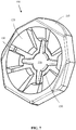
- Figure 6 shows the mounting box in a state in which a cable lead-in element has been cut off.
- the lead-in element 100 positioned in the first lead in 18C in the second planar surface section 11B in the bottom portion 11 of the bottom part 10 of the mounting box 400 has been cut off.
- the first lead-in 18C in the second planar surface section 11B forms now a tube lead-in.
- the cable lead-in element 100 forms an integral part of the bottom part 10 of the mounting box 400.
- the bottom part 10 of the mounting box 400 may be manufactured by injection moulding in a mould.
- the cable lead-ins and the tube lad-ins as well as the lead in elements are formed as one entity in a single injection moulding process.
- the cable lead-in element 100 protrudes outwards from the second planar surface section 11B. This makes it is easy to cut off the cable lead-in element 100 from the second planar surface section 11B in the bottom portion 10 of the mounting box 400.
- Figure 7 shows an enlargement of the cable lead-in element.
- the lead-in element 100 may comprise a flange 110, tongues 120, cuts 130, and a centre portion 140.
- the flange 110 may have a substantially annular form.
- the outer perimeter of the flange 110 may be substantially polygonal and the inner perimeter of the flange 110 may be substantially round or oval.
- the tongues 120 may be separated from each other with radially extending cuts 130.
- the radial length of the tongues 120 may vary so that each other flange 120 is longer and each other flange 120 is shorter.
- the tongues 120 may be curved inwards so that it is easy to push a cable through the cable lead-in element 100 from the outside of the cable lead-in element 100. It is on the other hand difficult to drag out the cable once it has been pushed through the cable lead-in element 100.
- the centre portion 140 of the flange 110 may be attached only to the radially shorter tongues 120. The centre portion 140 may be pushed out when the cable is pushed through the cable lead-in element 100.
- the tongues 120 form the strain relief in the cable lad-in element 100.
- An opening 150 is formed in the middle of the lead-in element 100 when the centre portion 140 is removed from the lead-in element 100. A smallest perimeter portion of the opening 150 is formed by the radially longer tongues 120 and a bigger perimeter portion is formed by the radially shorter tongues 120.
- Figure 8 shows a cross section of the cable lead-in element.
- the cross section shows that the cable lead-in element 100 may comprise a collar 160 below the flange 110 through which collar 160 the cable lead-in element 100 may become attached to the second planar surface section 11B.
- the cut off line CL may pass through the bottom of the collar 160.
- At least a portion of the collar 160 may comprise a weakened wall thickness in the cross section along the second planar surface section 11B in order to facilitate the cutting off of the lead-in element 100.
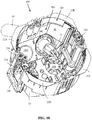
- Figure 9 shows a first view of the mounting box with a cable connected to the mounting box and figure 10 shows a second view of the mounting box with a cable connected to the mounting box.
- the cable 30 has been pushed through the cable lead-in 18C in the second planar surface section 11B of the bottom 10 of the mounting box 400.
- the wires 31 of the cable 30 are seen in the second view of the mounting box 400.
- Figure 11 shows a first view of the mounting box with a pipe connected to the mounting box and figure 12 shows a second view of the mounting box with a tube connected to the mounting box.
- the tube 40 has been pushed through the lead-in 18C in the second planar section 11B of the bottom 10 of the mounting box 400.
- the lead-in element 100 has been cut off from the lead-in before the tube 40 is pushed to lead-in 18C.
- the wires that run within the tube 40 are not shown in the second view of the mounting box 400.
- the tube 40 is flexible and has a corrugated construction. The tube 40 may be seated in the opening formed in the lead-in 18C when the lead-in element 100 has been removed so that a valley 41 in the corrugation seats against the edge of the opening. The tube 40 is thus secured to the opening in the lead-in 18C.
- Figure 12 shows further two stopper elements 19A, 19B positioned within the mounting box 100 and extending substantially vertically upwards from the planar first surface section 11A i.e. the bottom of the mounting box 400.
- the stopper elements 19A, 19B are positioned so that they form stoppers for the respective tube 40 to be pushed into the mounting box 400 from the tube lead in 18C, 18D. A lower portion of the end of the tube 40 will hit the respective stopper element 19A, 19B when the tube 40 is pushed into the mounting box 400.
- the stopper elements 19A, 19B will thereby prevent the tube 40 from being pushed too far into the mounting box 400.
- Figure 13 shows two mounting boxes mounted to a wall.
- the wall comprises a first wall 300 and a second parallel wall 310 at a distance from the first wall 300.
- the first wall 300 can be an inner wall 300 of a space e.g. a room, whereby the second wall 310 forms the outer wall 310 of the wall construction.
- the mounting box 400 is adapted to be installed into an opening 305 in the first wall 300 by pushing the mounting box 400 into the opening 305 of the first wall sheet 300 from a first side 301 of the first wall 300.
- the first side 301 of the first wall 300 is facing towards the interior of the space delimited by the wall structure.
- the mounting box 400 to the left in the figure is in a state where the axial X-X length L2 of the mounting box 400 is at a maximum.
- the mounting box 400 to the right in the figure is in a state where the axial X-X length L1 of the mounting box 400 is at a minimum.
- the thickness of the wall construction can vary so that the distance between the first wall 300 and the second wall 310 varies or so that the thickness of the first wall 300 varies. There is thus a need to be able to adapt the axial X-X length L1, L2 of the mounting box 400 according to this.
- the distance L1 from the first side 301 of the first wall 300 to the lead-ins 18A, 18B for the tubes and/or the cables at the bottom of the mounting box 400 is longer in the mounting box 400 situated to the left in the figure.
- the distance L2 from the first side 301 of the first wall 300 to the lead-ins 18A, 18B for the tubes and/or the cables is shorter in the mounting box 400 situated to the right in the figure.
- the mounting space within the mounting box 400 to the left in the figure is thus greater compared to the mounting space within the mounting box 400 to the right in the figure.
- This mounting space within the mounting box 400 can be adjusted at any time after the mounting box 400 has been attached to the wall 300 so that the flange means 22 seat against the first side 401 of the first wall 300.
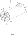
- Figure 14 shows a connection sleeve according to the invention.
- connection sleeve 500 forms a connection casing.
- the connection sleeve 500 comprises a body portion 510, an open O1 top end 520, and a substantially closed bottom 530.
- a space M1 is formed within the connection sleeve 500.
- the bottom 530 is provided with a planar surface section 540.
- the planar surface section 540 in the bottom 530 of the connection sleeve 500 comprises a lead-in 550.
- the lead in 550 is formed as a combined cable and tube lead-in 550 comprising an outwards from the planar surface section 540 extending lead-in element 100.
- the lead-in element 100 forms a cable lead-in with strain relief.
- a tube lead-in may be formed by cutting of the lead-in element 100 along the planar surface section of the connection sleeve 500.
- There may be a box 560 protruding out from a circumference of the connection sleeve 500 at the open O1 top end 520 of the connection sleeve 500.
- the box 560 may comprise a locking spring protruding into the connection sleeve 500.
- a tube may be pushed into the open O1 top end 520 of the connection sleeve 500. The locking spring locks the tube to the connection sleeve 500 when the tube is pushed into the connection sleeve 500.
- a cable may be pushed through the lead-in element 100 into the connection sleeve 500 and further through the tube connected to the open O1 tope end 520 of the connection sleeve 500 when the lead-in element 100 is in place.
- the conductors of the cable may then be connected e.g. in a mounting box into which the tube terminates.
- the cable will then run partly within a tube and partly without a tube. The cable is held in place by the strain relief in the lead-in element 100.
- a second tube may on the other hand be pushed into the tube lead-in in the bottom 530 of the connection sleeve 500 when the lead-in element 100 has been cut off.
- the connection sleeve 500 will in this case form a connection between two tubes of different size.
- the second tube connected to the tube lead-in in the bottom 530 of the connection sleeve 500 has a smaller outer perimeter compared to the first tube connected to the tube lead-in in the top end 520 of the connection sleeve 500.
- the outer perimeter of the body portion 21 of the top part 20 could also be elliptic or polygonal which means that the bottom part 10 must be elliptic or polygonal in a corresponding way. Also the opening into which the mounting box 400 is to be installed must have a cross section corresponding to the cross section of the mounting box 400.
- the longitudinal center axis X-X passes through a middle point at the first end 21A of the body portion 21 of the top part 20.
- the longitudinal center axis X-X is perpendicular to the flange plane defined by the flange members 22.
- Connection means 50, 60 e.g. based on adjusting screws that adjust the axial position of the bottom part 10 within the top part 20 could naturally be used instead of the connection means 50, 60 disclosed in the figures.
- the bottom part 10 can naturally be provided with lead-ins 18A, 18B in any position in the bottom portion 11 of the bottom part 10. There could be any number of lead-ins 18A, 18B in the bottom portion 11 positioned in any pattern in the bottom portion 11.
- the mounting box described in the figures is just one example of a mounting box in which the invention may be used.
- the invention may be used in any type of mounting box.
- the invention may be used in a mounting box of the first type or in a mounting box of the second type.
- the invention may e.g. be used in a mounting box being formed as one entity i.e. the bottom part 10 and the top part 20 are formed as one entity.
- the space M1 in the interior of such a mounting box is thus constant.
- the invention may also be used in a mounting box being formed of more than two parts.
- the size of the mounting box and the connection sleeve may vary. Also the size of the cable and tube lead-ins may vary. The size of the cable lead-ins in the figures is such that a cable having a diameter of 8 to 13 mm may be used. The size of the tube lead-ins is in the figures such that a tube having a diameter of 20 mm may be used.
- the mounting box and the connection sleeve may, however, be dimensioned e.g. so that tubes of 16 mm, 20 mm, 25 mm and 30 mm may be used and that cables with a diameter greater than 13 mm may be used.
- the mounting box is a wiring accessory that can be used as a distribution box for electrical wires and as a mounting box for an electrical component such as an electric switch, a socket, a TV socket etc.
- connection sleeve is a wiring accessory that can be used as a connection between tubes of different dimensions.
- the connection sleeve may also be used as a connection in which an electrical cable passes from an open installation into a closed installation i.e. into a tube.
- the material of the mounting box and of the connection sleeve may be plastic e.g. polypropylene (PP).
Landscapes
- Engineering & Computer Science (AREA)
- Architecture (AREA)
- Civil Engineering (AREA)
- Structural Engineering (AREA)
- Connection Or Junction Boxes (AREA)
Claims (14)
- Boîtier de connexion comprenant un corps (10, 20, 510) présentant un périmètre externe sensiblement fermé, une extrémité supérieure (21A, 520) ouverte (O1) et un fond sensiblement fermé (10, 530), un espace (M1) étant formé à l'intérieur du boîtier de connexion (400, 500), le fond (10) comprenant au moins une section de surface plane (11A, 11B, 11C, 540) ayant une surface externe et étant munie d'au moins une entrée (18A, 18B, 18C, 18D, 550), caractérisé en ce qu'au moins une entrée (18C, 550) est formée sous forme d'entrée combinée de câble et de tube (18C, 550) comprenantun élément d'entrée (100) s'étendant vers l'extérieur depuis la surface externe de la section de surface plane (11B, 540) le long d'une direction axiale perpendiculaire à la surface externe de la section de surface plane (11B, 540), l'élément d'entrée (100) étant formé en tant que partie intégrée au boîtier de connexion (400, 500), l'élément d'entrée (100) comprenant un collier (160) s'étendant axialement vers l'extérieur depuis la surface externe de la section de surface plane (11B, 540) et une bride (110) s'étendant axialement vers l'extérieur depuis le collier (160), l'élément d'entrée (100) formant une entrée de câble munie d'un détendeur (120) positionné à l'intérieur de la bride (110),une ouverture dans la section de surface plane (11B, 540) s'étendant à travers la section de surface plane (11B, 540), l'ouverture étant entourée par l'élément d'entrée (100), l'ouverture formant une entrée de tube, dans lequell'élément d'entrée (100) est agencé pour être coupé de la section de surface plane (11B, 540) le long d'une ligne de coupe (CL) passant à travers un fond du collier (160) au moyen de la coupe le long de la surface externe de la section de surface plane (11B, 540) afin de retirer l'élément d'entrée (100) et ainsi d'exposer l'entrée de tube.
- Boîtier de connexion selon la revendication 1, caractérisé en ce qu'au moins une partie du collier (160) comprend une épaisseur de paroi affaiblie dans la section transversale le long de la section de surface plane (11B) afin de faciliter la coupe de l'élément d'entrée (100).
- Boîtier de connexion selon les revendications 1 ou 2, caractérisé en ce que le détendeur (120) placé à l'intérieur de la bride (110) est formé de languettes flexibles (120) s'étendant dans une direction radiale vers l'intérieur depuis la bride (110), des brides adjacentes (120) étant séparées les unes des autres par des coupes s'étendant radialement (130).
- Boîtier de connexion selon la revendication 3, caractérisé en ce que des extrémités internes des languettes (120) se terminent à une distance les unes des autres, moyennant quoi une ouverture (150) est formée dans le centre de l'élément d'entrée (100).
- Boîtier de connexion selon la revendication 4, caractérisé en ce que la longueur des languettes (120) varie dans la direction radiale.
- Boîtier de connexion selon l'une quelconque des revendications 1 à 5, caractérisé en ce que le boîtier de connexion (400, 500) et l'élément d'entrée (100) sont formés en un unique processus de production.
- Boîtier de connexion selon la revendication 6, caractérisé en ce que le boîtier de connexion (400, 500) et donc également l'élément d'entrée (100) sont formés par moulage par injection.
- Boîtier de connexion selon l'une quelconque des revendications 1 à 6, caractérisé en ce que le boîtier de connexion (400, 500) est un boîtier de montage (400).
- Boîtier de connexion selon la revendication 8, caractérisé en ce qu'au moins un élément d'arrêt (19A, 19B) est placé dans l'intérieur du boîtier de montage (400), l'élément d'arrêt (19A, 19B) empêchant un tube (40) d'être poussé trop loin dans le boîtier de montage (400) .
- Boîtier de connexion selon la revendication 8 ou 9, caractérisé en ce que le boîtier de montage (400) comprend en outre des moyens de fixation (220, 230) coopérant avec des moyens de bride (22) s'étendant radialement vers l'extérieur depuis l'extrémité supérieure (21A) afin de fixer le boîtier de montage (400) à une paroi (300).
- Boîtier de connexion selon la revendication 10, caractérisé en ce que les moyens de fixation (220, 230) comprennent un élément de fixation (230) disposé dans une partie inférieure du boîtier de montage (400) et une vis de fixation (220) s'étendant depuis un sommet du boîtier de montage (400) vers l'élément de fixation (230), moyennant quoi la rotation de la vis de fixation (220) fait tourner tout d'abord l'élément de fixation (230) radialement vers l'extérieur du boîtier de montage (400) et la rotation supplémentaire de la vis de fixation (220) déplace l'élément de fixation (230) vers le haut de sorte que l'élément de fixation (230) s'assied contre une surface interne de la paroi (300), les moyens de bride (22) étant assis contre une surface externe de la paroi (300) et le boîtier de montage (400) étant fixé à la paroi (300).
- Boîtier de connexion selon l'une quelconque des revendications 9 à 11, caractérisé en ce que le boîtier de montage (400) est formé en tant qu'une seule entité.
- Boîtier de connexion selon l'une quelconque des revendications 9 à 11, caractérisé en ce que le boîtier de montage (400) est formé de deux parties ou plus pouvant être reliées (10, 20).
- Boîtier de connexion selon la revendication 13, caractérisé en ce que le boîtier de montage (400) est formé d'une partie inférieure (10) et d'une partie supérieure (20) pouvant bouger l'une par rapport à l'autre le long d'un axe central longitudinal (X-X) du boîtier de montage (400).
Priority Applications (2)
| Application Number | Priority Date | Filing Date | Title |
|---|---|---|---|
| EP17205887.7A EP3496219B1 (fr) | 2017-12-07 | 2017-12-07 | Boîtier de connexion |
| DK17205887.7T DK3496219T3 (da) | 2017-12-07 | 2017-12-07 | Forbindelseshylster |
Applications Claiming Priority (1)
| Application Number | Priority Date | Filing Date | Title |
|---|---|---|---|
| EP17205887.7A EP3496219B1 (fr) | 2017-12-07 | 2017-12-07 | Boîtier de connexion |
Publications (2)
| Publication Number | Publication Date |
|---|---|
| EP3496219A1 EP3496219A1 (fr) | 2019-06-12 |
| EP3496219B1 true EP3496219B1 (fr) | 2021-10-20 |
Family
ID=60629507
Family Applications (1)
| Application Number | Title | Priority Date | Filing Date |
|---|---|---|---|
| EP17205887.7A Active EP3496219B1 (fr) | 2017-12-07 | 2017-12-07 | Boîtier de connexion |
Country Status (2)
| Country | Link |
|---|---|
| EP (1) | EP3496219B1 (fr) |
| DK (1) | DK3496219T3 (fr) |
Families Citing this family (2)
| Publication number | Priority date | Publication date | Assignee | Title |
|---|---|---|---|---|
| CH716567A1 (de) * | 2019-09-06 | 2021-03-15 | Kaiser Gmbh & Co Kg | Installationsdose für elektronische Zwecke. |
| EP4564624A1 (fr) * | 2023-12-01 | 2025-06-04 | Schneider Electric Industries Sas | Ensemble de boîte d'installation pour fixer des fils de diamètres différents |
Citations (1)
| Publication number | Priority date | Publication date | Assignee | Title |
|---|---|---|---|---|
| US4424406A (en) * | 1978-02-21 | 1984-01-03 | Slater Electric Inc. | Cable entry port means for electrical outlet box |
Family Cites Families (7)
| Publication number | Priority date | Publication date | Assignee | Title |
|---|---|---|---|---|
| FR1307295A (fr) * | 1961-09-11 | 1962-10-26 | Legrand Ets | Bague de passage étanche d'un câble à travers une paroi |
| FR2856529B1 (fr) * | 2003-06-17 | 2005-07-29 | Schneider Electric Ind Sas | Dispositif de traversee etanche de paroi. |
| DE102004001069A1 (de) * | 2004-01-02 | 2005-08-04 | Hup Elektrotechnik Vertriebs-Gmbh | Hohlwanddose aus Kunststoff für elektrotechnische Installationen |
| DE202010014721U1 (de) * | 2010-10-28 | 2012-01-30 | Doyma Gmbh & Co | Dichtvorrichtung |
| DK2822119T3 (en) * | 2013-07-05 | 2016-03-07 | Abb Oy | Mounting box |
| LT3059817T (lt) * | 2015-02-20 | 2021-01-11 | Abb Schweiz Ag | Montažinė dėžutė |
| EP3059821A1 (fr) * | 2015-02-20 | 2016-08-24 | ABB Oy | Boîtier de montage et procédé de fabrication de boîtier de montage |
-
2017
- 2017-12-07 EP EP17205887.7A patent/EP3496219B1/fr active Active
- 2017-12-07 DK DK17205887.7T patent/DK3496219T3/da active
Patent Citations (1)
| Publication number | Priority date | Publication date | Assignee | Title |
|---|---|---|---|---|
| US4424406A (en) * | 1978-02-21 | 1984-01-03 | Slater Electric Inc. | Cable entry port means for electrical outlet box |
Also Published As
| Publication number | Publication date |
|---|---|
| EP3496219A1 (fr) | 2019-06-12 |
| DK3496219T3 (da) | 2022-01-17 |
Similar Documents
| Publication | Publication Date | Title |
|---|---|---|
| EP1993179B1 (fr) | Traversée de câble avec des moyens pour faciliter le passage du câble dans un sens et pour empêcher son retrait dans l'autre sens | |
| US6278061B1 (en) | Concentric retainer mechanism for variable diameter cables | |
| US6034326A (en) | Conduit connector assembly spring clip having scalloped shaped conduit gripping end | |
| US7332678B2 (en) | Button style cord connector | |
| US6849803B1 (en) | Electrical connector | |
| US5731543A (en) | Conduit connector assembly with end stop grommet for attachment of conduit to junction box | |
| US6604400B1 (en) | Electrical connector | |
| US6020557A (en) | Conduit connector assembly with angled conduit gripping means | |
| US7064272B2 (en) | Snap in electrical connector assembly with unidirectional wire conductor retainer ring | |
| US8106297B1 (en) | Grounded conduit bushing | |
| US7703813B1 (en) | Electrical connector with snap fit retaining ring with improved holding and grounding tangs | |
| US5831213A (en) | Electrical outlet box and removable clamp therefor | |
| US20090120687A1 (en) | Electrical connector with outer retainer ring and internal unidirectional conductor retainer | |
| US3369071A (en) | Electrical conduit connector | |
| US10644491B2 (en) | Electrical box cable connector | |
| EP3496219B1 (fr) | Boîtier de connexion | |
| US6177633B1 (en) | Cable connector | |
| EP3299690B1 (fr) | Disque d'étanchéité | |
| US1608621A (en) | Electrical conduit system | |
| WO2017079320A1 (fr) | Connecteur de câble électrique | |
| EP3026766B1 (fr) | Introduction de tube pour une boite de branchement | |
| US3328513A (en) | Electrical fitting entrance cap | |
| EP3059817B1 (fr) | Boîtier de montage | |
| CA2468274A1 (fr) | Connecteur encliquetable a prise de calibre | |
| EP3059821A1 (fr) | Boîtier de montage et procédé de fabrication de boîtier de montage |
Legal Events
| Date | Code | Title | Description |
|---|---|---|---|
| PUAI | Public reference made under article 153(3) epc to a published international application that has entered the european phase |
Free format text: ORIGINAL CODE: 0009012 |
|
| STAA | Information on the status of an ep patent application or granted ep patent |
Free format text: STATUS: THE APPLICATION HAS BEEN PUBLISHED |
|
| AK | Designated contracting states |
Kind code of ref document: A1 Designated state(s): AL AT BE BG CH CY CZ DE DK EE ES FI FR GB GR HR HU IE IS IT LI LT LU LV MC MK MT NL NO PL PT RO RS SE SI SK SM TR |
|
| AX | Request for extension of the european patent |
Extension state: BA ME |
|
| STAA | Information on the status of an ep patent application or granted ep patent |
Free format text: STATUS: REQUEST FOR EXAMINATION WAS MADE |
|
| 17P | Request for examination filed |
Effective date: 20191209 |
|
| RBV | Designated contracting states (corrected) |
Designated state(s): AL AT BE BG CH CY CZ DE DK EE ES FI FR GB GR HR HU IE IS IT LI LT LU LV MC MK MT NL NO PL PT RO RS SE SI SK SM TR |
|
| STAA | Information on the status of an ep patent application or granted ep patent |
Free format text: STATUS: EXAMINATION IS IN PROGRESS |
|
| 17Q | First examination report despatched |
Effective date: 20200616 |
|
| GRAP | Despatch of communication of intention to grant a patent |
Free format text: ORIGINAL CODE: EPIDOSNIGR1 |
|
| STAA | Information on the status of an ep patent application or granted ep patent |
Free format text: STATUS: GRANT OF PATENT IS INTENDED |
|
| INTG | Intention to grant announced |
Effective date: 20210519 |
|
| RAP3 | Party data changed (applicant data changed or rights of an application transferred) |
Owner name: ABB SCHWEIZ AG |
|
| GRAS | Grant fee paid |
Free format text: ORIGINAL CODE: EPIDOSNIGR3 |
|
| GRAA | (expected) grant |
Free format text: ORIGINAL CODE: 0009210 |
|
| STAA | Information on the status of an ep patent application or granted ep patent |
Free format text: STATUS: THE PATENT HAS BEEN GRANTED |
|
| AK | Designated contracting states |
Kind code of ref document: B1 Designated state(s): AL AT BE BG CH CY CZ DE DK EE ES FI FR GB GR HR HU IE IS IT LI LT LU LV MC MK MT NL NO PL PT RO RS SE SI SK SM TR |
|
| REG | Reference to a national code |
Ref country code: GB Ref legal event code: FG4D |
|
| REG | Reference to a national code |
Ref country code: CH Ref legal event code: EP |
|
| REG | Reference to a national code |
Ref country code: IE Ref legal event code: FG4D |
|
| REG | Reference to a national code |
Ref country code: DE Ref legal event code: R096 Ref document number: 602017047824 Country of ref document: DE |
|
| REG | Reference to a national code |
Ref country code: AT Ref legal event code: REF Ref document number: 1440709 Country of ref document: AT Kind code of ref document: T Effective date: 20211115 |
|
| REG | Reference to a national code |
Ref country code: FI Ref legal event code: FGE |
|
| REG | Reference to a national code |
Ref country code: DK Ref legal event code: T3 Effective date: 20220114 Ref country code: NO Ref legal event code: T2 Effective date: 20211020 |
|
| REG | Reference to a national code |
Ref country code: SE Ref legal event code: TRGR |
|
| REG | Reference to a national code |
Ref country code: NL Ref legal event code: FP |
|
| REG | Reference to a national code |
Ref country code: LT Ref legal event code: MG9D |
|
| REG | Reference to a national code |
Ref country code: AT Ref legal event code: MK05 Ref document number: 1440709 Country of ref document: AT Kind code of ref document: T Effective date: 20211020 |
|
| PG25 | Lapsed in a contracting state [announced via postgrant information from national office to epo] |
Ref country code: RS Free format text: LAPSE BECAUSE OF FAILURE TO SUBMIT A TRANSLATION OF THE DESCRIPTION OR TO PAY THE FEE WITHIN THE PRESCRIBED TIME-LIMIT Effective date: 20211020 Ref country code: LT Free format text: LAPSE BECAUSE OF FAILURE TO SUBMIT A TRANSLATION OF THE DESCRIPTION OR TO PAY THE FEE WITHIN THE PRESCRIBED TIME-LIMIT Effective date: 20211020 Ref country code: BG Free format text: LAPSE BECAUSE OF FAILURE TO SUBMIT A TRANSLATION OF THE DESCRIPTION OR TO PAY THE FEE WITHIN THE PRESCRIBED TIME-LIMIT Effective date: 20220120 Ref country code: AT Free format text: LAPSE BECAUSE OF FAILURE TO SUBMIT A TRANSLATION OF THE DESCRIPTION OR TO PAY THE FEE WITHIN THE PRESCRIBED TIME-LIMIT Effective date: 20211020 |
|
| PG25 | Lapsed in a contracting state [announced via postgrant information from national office to epo] |
Ref country code: IS Free format text: LAPSE BECAUSE OF FAILURE TO SUBMIT A TRANSLATION OF THE DESCRIPTION OR TO PAY THE FEE WITHIN THE PRESCRIBED TIME-LIMIT Effective date: 20220220 Ref country code: PT Free format text: LAPSE BECAUSE OF FAILURE TO SUBMIT A TRANSLATION OF THE DESCRIPTION OR TO PAY THE FEE WITHIN THE PRESCRIBED TIME-LIMIT Effective date: 20220221 Ref country code: PL Free format text: LAPSE BECAUSE OF FAILURE TO SUBMIT A TRANSLATION OF THE DESCRIPTION OR TO PAY THE FEE WITHIN THE PRESCRIBED TIME-LIMIT Effective date: 20211020 Ref country code: LV Free format text: LAPSE BECAUSE OF FAILURE TO SUBMIT A TRANSLATION OF THE DESCRIPTION OR TO PAY THE FEE WITHIN THE PRESCRIBED TIME-LIMIT Effective date: 20211020 Ref country code: HR Free format text: LAPSE BECAUSE OF FAILURE TO SUBMIT A TRANSLATION OF THE DESCRIPTION OR TO PAY THE FEE WITHIN THE PRESCRIBED TIME-LIMIT Effective date: 20211020 Ref country code: GR Free format text: LAPSE BECAUSE OF FAILURE TO SUBMIT A TRANSLATION OF THE DESCRIPTION OR TO PAY THE FEE WITHIN THE PRESCRIBED TIME-LIMIT Effective date: 20220121 Ref country code: ES Free format text: LAPSE BECAUSE OF FAILURE TO SUBMIT A TRANSLATION OF THE DESCRIPTION OR TO PAY THE FEE WITHIN THE PRESCRIBED TIME-LIMIT Effective date: 20211020 |
|
| REG | Reference to a national code |
Ref country code: DE Ref legal event code: R097 Ref document number: 602017047824 Country of ref document: DE |
|
| PG25 | Lapsed in a contracting state [announced via postgrant information from national office to epo] |
Ref country code: SM Free format text: LAPSE BECAUSE OF FAILURE TO SUBMIT A TRANSLATION OF THE DESCRIPTION OR TO PAY THE FEE WITHIN THE PRESCRIBED TIME-LIMIT Effective date: 20211020 Ref country code: SK Free format text: LAPSE BECAUSE OF FAILURE TO SUBMIT A TRANSLATION OF THE DESCRIPTION OR TO PAY THE FEE WITHIN THE PRESCRIBED TIME-LIMIT Effective date: 20211020 Ref country code: RO Free format text: LAPSE BECAUSE OF FAILURE TO SUBMIT A TRANSLATION OF THE DESCRIPTION OR TO PAY THE FEE WITHIN THE PRESCRIBED TIME-LIMIT Effective date: 20211020 Ref country code: MC Free format text: LAPSE BECAUSE OF FAILURE TO SUBMIT A TRANSLATION OF THE DESCRIPTION OR TO PAY THE FEE WITHIN THE PRESCRIBED TIME-LIMIT Effective date: 20211020 Ref country code: EE Free format text: LAPSE BECAUSE OF FAILURE TO SUBMIT A TRANSLATION OF THE DESCRIPTION OR TO PAY THE FEE WITHIN THE PRESCRIBED TIME-LIMIT Effective date: 20211020 Ref country code: CZ Free format text: LAPSE BECAUSE OF FAILURE TO SUBMIT A TRANSLATION OF THE DESCRIPTION OR TO PAY THE FEE WITHIN THE PRESCRIBED TIME-LIMIT Effective date: 20211020 |
|
| REG | Reference to a national code |
Ref country code: CH Ref legal event code: PL |
|
| PLBE | No opposition filed within time limit |
Free format text: ORIGINAL CODE: 0009261 |
|
| STAA | Information on the status of an ep patent application or granted ep patent |
Free format text: STATUS: NO OPPOSITION FILED WITHIN TIME LIMIT |
|
| REG | Reference to a national code |
Ref country code: BE Ref legal event code: MM Effective date: 20211231 |
|
| 26N | No opposition filed |
Effective date: 20220721 |
|
| GBPC | Gb: european patent ceased through non-payment of renewal fee |
Effective date: 20220120 |
|
| PG25 | Lapsed in a contracting state [announced via postgrant information from national office to epo] |
Ref country code: LU Free format text: LAPSE BECAUSE OF NON-PAYMENT OF DUE FEES Effective date: 20211207 Ref country code: IE Free format text: LAPSE BECAUSE OF NON-PAYMENT OF DUE FEES Effective date: 20211207 Ref country code: GB Free format text: LAPSE BECAUSE OF NON-PAYMENT OF DUE FEES Effective date: 20220120 Ref country code: AL Free format text: LAPSE BECAUSE OF FAILURE TO SUBMIT A TRANSLATION OF THE DESCRIPTION OR TO PAY THE FEE WITHIN THE PRESCRIBED TIME-LIMIT Effective date: 20211020 |
|
| PG25 | Lapsed in a contracting state [announced via postgrant information from national office to epo] |
Ref country code: SI Free format text: LAPSE BECAUSE OF FAILURE TO SUBMIT A TRANSLATION OF THE DESCRIPTION OR TO PAY THE FEE WITHIN THE PRESCRIBED TIME-LIMIT Effective date: 20211020 Ref country code: FR Free format text: LAPSE BECAUSE OF NON-PAYMENT OF DUE FEES Effective date: 20211220 Ref country code: BE Free format text: LAPSE BECAUSE OF NON-PAYMENT OF DUE FEES Effective date: 20211231 |
|
| PG25 | Lapsed in a contracting state [announced via postgrant information from national office to epo] |
Ref country code: LI Free format text: LAPSE BECAUSE OF NON-PAYMENT OF DUE FEES Effective date: 20211231 Ref country code: CH Free format text: LAPSE BECAUSE OF NON-PAYMENT OF DUE FEES Effective date: 20211231 |
|
| PG25 | Lapsed in a contracting state [announced via postgrant information from national office to epo] |
Ref country code: IT Free format text: LAPSE BECAUSE OF FAILURE TO SUBMIT A TRANSLATION OF THE DESCRIPTION OR TO PAY THE FEE WITHIN THE PRESCRIBED TIME-LIMIT Effective date: 20211020 |
|
| PG25 | Lapsed in a contracting state [announced via postgrant information from national office to epo] |
Ref country code: CY Free format text: LAPSE BECAUSE OF FAILURE TO SUBMIT A TRANSLATION OF THE DESCRIPTION OR TO PAY THE FEE WITHIN THE PRESCRIBED TIME-LIMIT Effective date: 20211020 |
|
| PG25 | Lapsed in a contracting state [announced via postgrant information from national office to epo] |
Ref country code: HU Free format text: LAPSE BECAUSE OF FAILURE TO SUBMIT A TRANSLATION OF THE DESCRIPTION OR TO PAY THE FEE WITHIN THE PRESCRIBED TIME-LIMIT; INVALID AB INITIO Effective date: 20171207 |
|
| PG25 | Lapsed in a contracting state [announced via postgrant information from national office to epo] |
Ref country code: MK Free format text: LAPSE BECAUSE OF FAILURE TO SUBMIT A TRANSLATION OF THE DESCRIPTION OR TO PAY THE FEE WITHIN THE PRESCRIBED TIME-LIMIT Effective date: 20211020 |
|
| PG25 | Lapsed in a contracting state [announced via postgrant information from national office to epo] |
Ref country code: MT Free format text: LAPSE BECAUSE OF FAILURE TO SUBMIT A TRANSLATION OF THE DESCRIPTION OR TO PAY THE FEE WITHIN THE PRESCRIBED TIME-LIMIT Effective date: 20211020 |
|
| PG25 | Lapsed in a contracting state [announced via postgrant information from national office to epo] |
Ref country code: TR Free format text: LAPSE BECAUSE OF FAILURE TO SUBMIT A TRANSLATION OF THE DESCRIPTION OR TO PAY THE FEE WITHIN THE PRESCRIBED TIME-LIMIT Effective date: 20211020 |
|
| PGFP | Annual fee paid to national office [announced via postgrant information from national office to epo] |
Ref country code: DE Payment date: 20251211 Year of fee payment: 9 |
|
| PGFP | Annual fee paid to national office [announced via postgrant information from national office to epo] |
Ref country code: FI Payment date: 20251223 Year of fee payment: 9 Ref country code: DK Payment date: 20251224 Year of fee payment: 9 |
|
| PGFP | Annual fee paid to national office [announced via postgrant information from national office to epo] |
Ref country code: NL Payment date: 20251219 Year of fee payment: 9 |
|
| PGFP | Annual fee paid to national office [announced via postgrant information from national office to epo] |
Ref country code: SE Payment date: 20251219 Year of fee payment: 9 |
|
| PGFP | Annual fee paid to national office [announced via postgrant information from national office to epo] |
Ref country code: NO Payment date: 20251230 Year of fee payment: 9 |