EP3496224A2 - Systeme und verfahren zur verteilung von elektrischer energie in solarkraftanlagen - Google Patents
Systeme und verfahren zur verteilung von elektrischer energie in solarkraftanlagen Download PDFInfo
- Publication number
- EP3496224A2 EP3496224A2 EP18209768.3A EP18209768A EP3496224A2 EP 3496224 A2 EP3496224 A2 EP 3496224A2 EP 18209768 A EP18209768 A EP 18209768A EP 3496224 A2 EP3496224 A2 EP 3496224A2
- Authority
- EP
- European Patent Office
- Prior art keywords
- photovoltaic
- converter
- power
- architecture
- strings
- Prior art date
- Legal status (The legal status is an assumption and is not a legal conclusion. Google has not performed a legal analysis and makes no representation as to the accuracy of the status listed.)
- Withdrawn
Links
Images



Classifications
-
- H—ELECTRICITY
- H02—GENERATION; CONVERSION OR DISTRIBUTION OF ELECTRIC POWER
- H02J—ELECTRIC POWER NETWORKS; CIRCUIT ARRANGEMENTS OR SYSTEMS FOR SUPPLYING OR DISTRIBUTING ELECTRIC POWER; SYSTEMS FOR STORING ELECTRIC ENERGY
- H02J1/00—Circuit arrangements for DC mains or DC distribution networks
- H02J1/10—Parallel operation of DC sources
- H02J1/12—Parallel operation of DC sources having power converters with further DC sources without power converters
-
- H—ELECTRICITY
- H02—GENERATION; CONVERSION OR DISTRIBUTION OF ELECTRIC POWER
- H02J—ELECTRIC POWER NETWORKS; CIRCUIT ARRANGEMENTS OR SYSTEMS FOR SUPPLYING OR DISTRIBUTING ELECTRIC POWER; SYSTEMS FOR STORING ELECTRIC ENERGY
- H02J3/00—Circuit arrangements for AC mains or AC distribution networks
- H02J3/38—Arrangements for feeding a single network from two or more generators or sources in parallel; Arrangements for feeding already energised networks from additional generators or sources in parallel
- H02J3/381—Dispersed generators
-
- H—ELECTRICITY
- H02—GENERATION; CONVERSION OR DISTRIBUTION OF ELECTRIC POWER
- H02S—GENERATION OF ELECTRIC POWER BY CONVERSION OF INFRARED RADIATION, VISIBLE LIGHT OR ULTRAVIOLET LIGHT, e.g. USING PHOTOVOLTAIC [PV] MODULES
- H02S40/00—Components or accessories in combination with PV modules, not provided for in groups H02S10/00 - H02S30/00
- H02S40/30—Electrical components
- H02S40/32—Electrical components comprising DC/AC inverter means associated with the PV module itself, e.g. AC modules
-
- H—ELECTRICITY
- H02—GENERATION; CONVERSION OR DISTRIBUTION OF ELECTRIC POWER
- H02S—GENERATION OF ELECTRIC POWER BY CONVERSION OF INFRARED RADIATION, VISIBLE LIGHT OR ULTRAVIOLET LIGHT, e.g. USING PHOTOVOLTAIC [PV] MODULES
- H02S40/00—Components or accessories in combination with PV modules, not provided for in groups H02S10/00 - H02S30/00
- H02S40/30—Electrical components
- H02S40/36—Electrical components characterised by special electrical interconnection means between two or more PV modules, e.g. electrical module-to-module connection
-
- H—ELECTRICITY
- H02—GENERATION; CONVERSION OR DISTRIBUTION OF ELECTRIC POWER
- H02J—ELECTRIC POWER NETWORKS; CIRCUIT ARRANGEMENTS OR SYSTEMS FOR SUPPLYING OR DISTRIBUTING ELECTRIC POWER; SYSTEMS FOR STORING ELECTRIC ENERGY
- H02J2101/00—Supply or distribution of decentralised, dispersed or local electric power generation
- H02J2101/20—Dispersed power generation using renewable energy sources
- H02J2101/22—Solar energy
- H02J2101/24—Photovoltaics
-
- Y—GENERAL TAGGING OF NEW TECHNOLOGICAL DEVELOPMENTS; GENERAL TAGGING OF CROSS-SECTIONAL TECHNOLOGIES SPANNING OVER SEVERAL SECTIONS OF THE IPC; TECHNICAL SUBJECTS COVERED BY FORMER USPC CROSS-REFERENCE ART COLLECTIONS [XRACs] AND DIGESTS
- Y02—TECHNOLOGIES OR APPLICATIONS FOR MITIGATION OR ADAPTATION AGAINST CLIMATE CHANGE
- Y02E—REDUCTION OF GREENHOUSE GAS [GHG] EMISSIONS, RELATED TO ENERGY GENERATION, TRANSMISSION OR DISTRIBUTION
- Y02E10/00—Energy generation through renewable energy sources
- Y02E10/50—Photovoltaic [PV] energy
- Y02E10/56—Power conversion systems, e.g. maximum power point trackers
Definitions
- the field of the disclosure relates generally to solar power plants and more particularly to the distribution of electrical power within a solar power plant.
- Solar power plants harvest sunlight to generate electrical power. Specifically, solar power plants may convert the solar energy in sunlight directly into electrical power using photovoltaic (PV) cells. Alternatively, solar power plants may use the sunlight indirectly as a heat source to produce electrical power.
- PV photovoltaic
- FIG. 1 illustrates a schematic diagram of a layout of a known one hundred megawatt PV solar power plant 10.
- Solar power plant 10 is divided into a plurality of PV power blocks 11.
- solar power plant 10 includes forty PV power blocks 11, each PV power block 11 producing 2.5 megawatts of power.
- the power from each PV power block 11 is delivered to a power substation 13, where the power is converted to match the requirements of a power grid (not shown) connected to solar power plant 10.
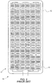
- FIG. 2 illustrates a schematic diagram of a known PV module 12 for use in a PV power plant such as solar power plant 10 (shown in FIG. 1 ).
- PV module 12 includes a plurality of PV cells 15 that are electrically coupled in series with one another.
- the plurality of PV cells 15 are arranged in twelve rows 17 and six columns 19, for a total of seventy-two PV cells 15 electrically connected in series.
- Each PV cell 15 is operable to convert photons from received light into electricity.
- Each PV cell 15 produces a low voltage as photons are absorbed, such as approximately 0.75 volts (V) when exposed to sunlight with no load. Because each PV cell is connected in series, the current is constant throughout the PV cells 15 while the voltage is additive.
- PV module 12 may produce an open circuit voltage of approximately 72 x 0.75 V, or 54 V. At full power, the voltage drops about 70% (e.g., to 38 V) with a current of about 9 amps (A) to produce a nominal maximum power of 342 watts (W) per PV module 12.
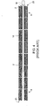
- FIG. 3 illustrates a schematic diagram of a known PV string 14. Specifically, each PV module 12 is electrically connected in series with other PV modules 12 to form PV string 14. PV string 14 may contain twenty-eight PV modules 12 connected in series, resulting in a nominal voltage of about 1491 V with no load. At a maximum power of about 9.1 Kilowatts per PV string 14, the voltage drops to about 1,042 V with a current of about 9 amps.
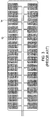
- FIG. 4 illustrates a schematic of first row 21 and a second row 23 that form a portion of PV power block 11.
- Each string row 21, 23 includes eight PV strings 14 for a total of sixteen PV strings 14.
- PV strings 14 are electrically connected in parallel to a combiner box 16, which combines output currents of PV strings 14.
- Each PV string 14 is connected to combiner box 16 using a pair of low voltage direct current (LVDC) cable 2 (for clarity, LVDC cable 2 is shown only for farthest strings 3 and nearest strings 4).
- LVDC low voltage direct current
- combiner box 16 for two rows 21, 23 of PV strings 14 requires sixteen pairs of LVDC cables 2. Because PV strings 14 are connected in parallel, the voltage does not increase, but the current is cumulative.
- combiner box 16 may combine the output of sixteen PV strings 14 to produce a total output of about 145.6 kilowatts at about 1,042 V and about 140 A.
- FIG. 5 illustrates a schematic diagram of PV power block 11.
- PV power block 11 includes two sets of twenty-four rows of PV strings 14 feeding twelve combiner boxes 16. An output of the combiner boxes 16 is connected to a block inverter 18 in parallel. Thus, twelve combiner boxes 16 may use twelve pairs of LVDC cables 5 to connect to block inverter 18 (for clarity, only a single pair of LVDC cables 5 is shown).
- Block inverter 18 converts the DC power produced by the PV cells to AC power, and a block transformer 20 steps up the AC voltage for transmitting to substation 13.
- Solar power plant 10 has various drawbacks.
- U.S. Patent Publication 2016/0099572A1 details the drawbacks for the above mentioned standard utility scale solar plant design.
- each PV string 14 is connected to combiner box 16 in parallel. This requires using relatively long (tens of meters to hundreds of meters) LVDC cables 2 for each PV string 14.
- typical utility scale PV plants have tens of thousands of PV strings 14 each requiring separate LVDC cables 2.
- the high number of LVDC cables 2 results in significant costs and resistive power losses.
- LVDC cables 5 coupled between the combiner boxes 16 and the block inverter 18 transmit the DC power to block inverter 18. Due to the relatively low DC voltage, the typical current on these LVDC cables 5 can be relatively high (100s A), requiring the use of large gauge LVDC cable and incurring significant power loss.
- a power generation architecture for a photovoltaic power plant includes a plurality of photovoltaic blocks and a medium voltage direct current collector.
- Each plurality of photovoltaic blocks includes a plurality of photovoltaic groups and a combiner.
- Each plurality of photovoltaic groups includes a plurality of photovoltaic strings and a direct current (DC) to DC power converter.
- Each photovoltaic string is operable to output low voltage, direct current (LVDC) electrical power at a string output.
- Each DC to DC power converter is electrically coupled to the string output of each photovoltaic string and is operable to convert the LVDC electrical power to medium voltage, direct current (MVDC) electrical power at a converter output.
- the combiner has a combiner input in electrical communication with each of the converter outputs of the plurality of photovoltaic groups and is operable to combine the MVDC electrical power received at the combiner input to produce a block output.
- the collector includes a collector input electrically coupled to each combiner output and operable to combine each block output.
- a power generation architecture for use in a photovoltaic power plant.
- the architecture includes a first photovoltaic group including a first plurality of photovoltaic strings and a first direct current (DC) to DC converter having an input electrically coupled to each photovoltaic string of the first plurality of photovoltaic strings.
- the architecture further includes a second photovoltaic group including a second plurality of photovoltaic strings and a second DC to DC converter having an input electrically coupled to each photovoltaic string of the second plurality of photovoltaic strings.
- the first photovoltaic group and the second photovoltaic group are physically arranged in a row and the first DC to DC power converter and the second DC to DC power converter are connected in a ring electrical connection.
- Approximating language may be applied to modify any quantitative representation that could permissibly vary without resulting in a change in the basic function to which it is related. Accordingly, a value modified by a term or terms, such as “about” and “substantially”, are not to be limited to the precise value specified. In at least some instances, the approximating language may correspond to the precision of an instrument for measuring the value.
- range limitations may be combined and/or interchanged, such ranges are identified and include all the sub-ranges contained therein unless context or language indicates otherwise.
- Low voltage is considered to be voltage up to approximately 1,500V
- medium voltage is considered to be voltage between approximately 1,500 V and 35kV
- high voltage is considered to be voltage between approximately 35kV and 230kV.
- a ring electrical connection is a variation of a parallel electric circuit.
- the ring connection connects terminals of adjacent sources. For example, a group of batteries would each have their positive terminals electrically coupled to one another and their negative terminals electrically coupled to one another. A single pair of leads may then be used at any battery terminal to tap the electrical power.
- Embodiments of the present disclosure relate to photovoltaic power plants.
- the photovoltaic power plants described herein include a configuration of photovoltaic strings that results in reduced material costs for constructing the plant as compared to at least some known string configurations.
- the string configuration described herein employs medium voltage direct current (MVDC) DC/DC converters to reduce the amount of wiring required.
- MVDC medium voltage direct current
- FIG. 6 illustrates a schematic diagram of an exemplary layout 44 of a group of PV strings 14.
- a PV string 14, as used herein, refers to a grouping of PV modules 12 connected in a series electrical connection.
- a PV module 12, as used herein, refers to a grouping of PV cells 15 electrically coupled to one another and sharing a common support structure.
- layout 44 includes four PV strings 14 that supply electrical power to one local DC/DC converter 40.
- PV strings 14 may be arranged symmetrically, with symmetry about a first axis 31 and a second axis 33. PV strings 14 may be arranged in a rectangle.
- Local DC/DC converter 40 may be located between PV strings 14 (e.g.
- each LVDC cable 38 may have the same length.
- identical LVDC cables may be used to electrically connect any PV string 14 to local DC/DC converter 40.
- Local DC/DC converter 40 subsequently steps up the LVDC voltage output from PV strings 14 to MVDC voltage levels. For example, a 1,042 V DC output of a single PV string 14 may be converted to approximately 20,000 VDC with a current of approximately .46 A using local DC/DC converter 40. Accordingly, the output of four PV strings 14 would be approximately 20,000 VDC with a current of 1.8 A. The higher relative voltage reduces the amount of electric current carried in any subsequent cabling by an order of magnitude.
- FIG. 7 illustrates a schematic diagram of a layout 47 of two rows 46, 48 of a PV block 42 using exemplary layouts 44 of groups of PV strings 14.
- a first row 46 includes eight PV strings 14 and a second row 48 includes eight PV strings 14.
- rows 46, 48 include sixteen PV strings 14 and four local DC/DC converters 40 with each layout 44 of four PV strings 14 electrically coupled to a local DC/DC converter 40.
- Local DC/DC converters 40 are each electrically connected in a ring electrical connection using a pair of MVDC cables 49, 55. Connecting local DC/DC converters 40 in a ring electrical connection results in increased current relative to a single DC/DC converter 40, but reduces the amount of MVDC cable 49 required for a given row.
- rows 46, 48 may together produce an output of approximately 20,000 VDC with a current of 7.3 A.
- traditional PV rows 21, 23 (shown in FIG. 2 ) output approximately 1,042 V and approximately 140 A each, and combined traditional PV rows 21, 23 output approximately 1,042 V and approximately 280 A.
- a MVDC cable carries less current than a LVDC cable, a MVDC cable experiences significantly lower power losses per length than a LVDC cable.
- a length of rows 46, 48 may be extended significantly by adding additional layouts 44 without incurring significant voltage drops/power losses.
- Current rows, such as rows 21, 23 are limited in length by the length of LVDC cable 2 required for the farthest PV string 14 (i.e. the PV string 14 farthest from the combiner box 16). If PV string 14 is too far away, the power losses in the LVDC cable become excessive.
- most conventional PV power plants have rows 21, 23 of eight PV strings 14.
- a farthest string 53 uses the same length of LVDC cable 38 as a nearest string 53.
- rows 46, 48 could be extended to sixteen PV strings 14 (for thirty-two total strings) without incurring significant voltage drops and/or power losses.
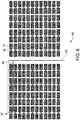
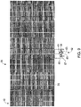
- FIG. 8 illustrates a schematic diagram of a PV power block 42 using multiple layouts 47 of rows of PV strings 14.
- PV power block 42 includes forty-eight rows of PV strings 14 (i.e., twenty-four for each side) and ninety-six local DC/DC converters 40.
- output of layout 47 is electrically connected to a block collector 50 (only one electrical connection of layout 47 is shown for clarity). Because the output of each layout 47 is MVDC with relatively low current, the output may be collected in a ring electrical connection without requiring a high current capacity of block collector 50. For example, the total current of forty-eight rows may be approximately 174.7 A, which is comparable to the current of a single row of a traditional PV power plant.
- This electrical power may be delivered to a power substation 52 using a conventional distribution system 56.
- FIG. 9 illustrates a schematic diagram of an exemplary PV power plant 54.
- PV power plant 54 includes a plurality of PV power blocks 42, an electrical distribution system 56, and a power substation 52. Each PV power block 42 is electrically coupled to power substation 52 through electrical distribution system 56. Electrical distribution system 56 may connect each PV power block 42 to power substation 52 in a parallel electrical connection, or in some embodiments, groups of PV power blocks 42 may be connected in a ring electrical connection.
- Power substation 52 includes an inverter 58 and a transformer 60 in the exemplary embodiment.
- Inverter 58 includes an input 61 in electrical communication with electrical distribution system 56 and an output 63 in electrical communication with an input 65 of transformer 60.
- Inverter 58 is operable to convert DC power received from electrical distribution system 56 to AC power.
- Inverter 58 may be silicon carbide based to operate at higher frequencies and temperatures compared to silicon based power electronics.
- Transformer 60 includes an input 65 in electrical communication with inverter 58 and an output 67 configured to connect to a power grid (not shown).
- Transformer 60 is operable to convert the AC power output by inverter 58 into a voltage compatible with the power grid.
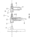
- FIG. 10 illustrates an exemplary connector 100 that serves both as a cable termination and as a quick disconnector to local DC/DC converters 40.
- Connector 100 includes a body portion 104 with a cable aperture 110 sized and shaped to receive MVDC cable 102.
- MVDC cable 102 is secured within cable aperture 110 using conventional techniques such as a compression fitting.
- Connector 100 further includes a head portion 106 having a lug aperture 112 sized and shaped to receive a lug 114 of an electrical component. Lug aperture 112 may be secured to lug 114 using conventional techniques.
- Head portion 106 includes a lug 108 opposite lug aperture 112.
- Lug 108 is sized and shaped to simulate a standard electrical lug 114.
- Cable aperture 110, lug aperture 112, and lug 108 are each in electrical connection with one another.
- a MVDC cable 102 may be electrically coupled to an electrical component by coupling MVDC cable 102 to cable aperture 110 and lug aperture 112 to lug 114 of electrical component.
- Connector 100 may be coupled to an existing connector 116 by coupling lug aperture 112 of connector 100 to lug 108 of existing connector 116.
- Connector 100 offers safe isolation of local DC/DC converter 40 from the rest of the PV plant and allows safe access to local DC/DC converter 40 for maintenance, repair or replacement.
- the multifunctional nature of connector 100 also further reduces the hardware cost by eliminating the need for a separate junction box.
- the following table details the distribution cost of an example architecture of a conventional PV power plant 10 having a block inverter 18 and block transformer 20 for each PV power block 11 as shown in FIGS. 1-5 .
- the cost is derived as the total cost of the components divided by the rated capacity of a power plant.
- the category “LVDC cable, Misc” includes the LVDC cables that are required to connect the individual photovoltaic strings to the combiner box. This category further includes the cable connectors that are used to quickly connect sections of LVDC cables to enable fast installation.
- the combiner box refers to the electrical combiner box that combine LVDC cables from multiple photovoltaic strings, provides electrical protection such as electrical fuse for each individual photovoltaic string and quick electrical disconnect function to allow fast isolating the string assembly from the rest of the PV plant for troubleshooting or maintenance.
- the category “LVDC cable to skid” refers to the LVDC cables that connect the combiner boxes to the block inverter/transformer skid.
- the "Inverter skid” refers to the block inverter and block transformer that are typically collocated on the same skid.
- the skid further has the additional electrical equipment such as LVDC cable recombiner (combines all LVDC cables from the combiner boxes), auxiliary power supply to supply power for plant control and communication equipment, MVAC switchgear, and ring main unit (RMU) for forming ring electrical connection for MVAC power output.
- LVDC cable recombiner combines all LVDC cables from the combiner boxes
- MVAC switchgear auxiliary power supply to supply power for plant control and communication equipment
- RMU ring main unit
- the "MVAC cable within section” refers to the MVAC cables (3 phase MVAC) that form ring electrical connection between the blocks.
- the "MVAC cable section to switch gear” refers to the MVAC cables from the last RMU in the ring connection to the MVAC power collector in the substation.
- the "MVAC switchgear” refers to the MVAC power collector in the substation.
- the "Tsfm+SF6+substation+SCADA” includes the transformer located in the substation that steps up voltage to the grid compatible voltage, the dielectric SF6 gas enabled high voltage switchgear that provide safe protection/disconnection between the substation transformer and the grid, all the infrastructure and equipment in substation that are required, and the Supervisory Control And Data Acquisition (SCADA) that is required for plant control.
- SCADA Supervisory Control And Data Acquisition
- the cost is further reduced to 13.07 ⁇ /W as shown in the table. Further, if the junction boxes are eliminated using connectors 100 of FIG. 10 , the costs further decreases as follows. LVDC cable, misc DC-DC Converter MVDC cable and connectors Substation Inverter Block Combiner Substation Misc. Total Cost (c/Wac) .86 3.74 3.13 2.07 .15 2.57 .2 12.73
- Eliminating the junction boxes reduces the cost of each DC-DC converter, further reducing the overall cost of the PV plant. Future reductions in the cost of the MVDC cable are possible. For example, standardized cable lengths and connectors may further reduce costs. If the termination cost is reduced to $100 per cable, the cost is as follows. LVDC cable, misc DC-DC Converter MVDC cable and connectors Substation Inverter Block Combiner Substation Misc. Total Cost (c/Wac) .86 3.74 2.04 2.07 .15 2.57 .2 11.63
- the cost per watt of a PV power plant may be reduced significantly using the exemplary PV string layout described herein, from 16.8 ⁇ /W to as low as 11.63 ⁇ /W.
- the exemplary PV string layout is advantageous in that it allows longer rows, decreases the amount of LVDC cabling, reduces high amperage losses, and reduces the overall cost of a PV power plant.
- Exemplary embodiments of a PV string layout and PV power plant are described above in detail.
- the system is not limited to the specific embodiments described herein, but rather, components of systems and/or steps of the methods may be utilized independently and separately from other components and/or steps described herein.
- the configuration of components described herein may also be used in combination with other processes, and is not limited to practice with the systems and related methods as described herein. Rather, the exemplary embodiments can be implemented and utilized in connection with many applications where monitoring of a power circuit is desired.
Landscapes
- Engineering & Computer Science (AREA)
- Power Engineering (AREA)
- Photovoltaic Devices (AREA)
- Direct Current Feeding And Distribution (AREA)
- Control Of Electrical Variables (AREA)
Applications Claiming Priority (1)
| Application Number | Priority Date | Filing Date | Title |
|---|---|---|---|
| US15/831,871 US20190173419A1 (en) | 2017-12-05 | 2017-12-05 | Systems and method for electrical power distribution in solar power plants |
Publications (2)
| Publication Number | Publication Date |
|---|---|
| EP3496224A2 true EP3496224A2 (de) | 2019-06-12 |
| EP3496224A3 EP3496224A3 (de) | 2019-07-24 |
Family
ID=64572179
Family Applications (1)
| Application Number | Title | Priority Date | Filing Date |
|---|---|---|---|
| EP18209768.3A Withdrawn EP3496224A3 (de) | 2017-12-05 | 2018-12-03 | Systeme und verfahren zur verteilung von elektrischer energie in solarkraftanlagen |
Country Status (2)
| Country | Link |
|---|---|
| US (1) | US20190173419A1 (de) |
| EP (1) | EP3496224A3 (de) |
Families Citing this family (2)
| Publication number | Priority date | Publication date | Assignee | Title |
|---|---|---|---|---|
| KR101937974B1 (ko) * | 2018-05-08 | 2019-01-14 | 주식회사 에이엘테크 | 광섬유 발광형 표지 장치 |
| WO2022133695A1 (zh) * | 2020-12-22 | 2022-06-30 | 华为数字能源技术有限公司 | 一种光伏发电系统、功率控制方法及汇流箱 |
Citations (1)
| Publication number | Priority date | Publication date | Assignee | Title |
|---|---|---|---|---|
| US20160099572A1 (en) | 2014-10-02 | 2016-04-07 | First Solar, Inc. | System for operation of photovoltaic power plant and dc power collection within |
Family Cites Families (7)
| Publication number | Priority date | Publication date | Assignee | Title |
|---|---|---|---|---|
| US20090020149A1 (en) * | 2007-07-16 | 2009-01-22 | Woods Lawrence M | Hybrid Multi-Junction Photovoltaic Cells And Associated Methods |
| US8716889B2 (en) * | 2011-03-14 | 2014-05-06 | Chandramouli Vaidyanathan | Solar powered electrical generation device and related methods |
| US9300140B2 (en) * | 2012-06-28 | 2016-03-29 | General Electric Company | System and method for design and optimization of grid connected photovoltaic power plant with multiple photovoltaic module technologies |
| WO2014121826A1 (en) * | 2013-02-06 | 2014-08-14 | Abb Technology Ltd | Solar power plant, method of controlling a solar power plant and a dc/dc conversion system |
| EP3142153B1 (de) * | 2015-09-12 | 2020-04-01 | IMEC vzw | Neukonfigurierbares photovoltaikmodul |
| US10256732B2 (en) * | 2015-10-16 | 2019-04-09 | General Electric Company | Power conversion system and method of operating the same |
| ES2804248T3 (es) * | 2017-03-07 | 2021-02-05 | Marici Holdings The Netherlands Bv | Sistema de planta de energía fotovoltaica |
-
2017
- 2017-12-05 US US15/831,871 patent/US20190173419A1/en not_active Abandoned
-
2018
- 2018-12-03 EP EP18209768.3A patent/EP3496224A3/de not_active Withdrawn
Patent Citations (1)
| Publication number | Priority date | Publication date | Assignee | Title |
|---|---|---|---|---|
| US20160099572A1 (en) | 2014-10-02 | 2016-04-07 | First Solar, Inc. | System for operation of photovoltaic power plant and dc power collection within |
Also Published As
| Publication number | Publication date |
|---|---|
| EP3496224A3 (de) | 2019-07-24 |
| US20190173419A1 (en) | 2019-06-06 |
Similar Documents
| Publication | Publication Date | Title |
|---|---|---|
| US11228178B2 (en) | Photovoltaic power plant system | |
| EP2810353B1 (de) | Dc-verbindungsschema für windpark mit internem mvdc-sammelgitter | |
| CN204103503U (zh) | 一种基于中高压直流接入的光伏并网发电系统 | |
| CN102272943B (zh) | 包括直接由光伏发电设备供应的高压dc传输装置的电源系统 | |
| CN102801177A (zh) | 用于直流电力传输的方法和系统 | |
| US8648498B1 (en) | Photovoltaic power system with distributed photovoltaic string to polyphase AC power converters | |
| JP2023549133A (ja) | マルチポート・エネルギー・ルーティング・システム | |
| US8699209B2 (en) | Externally fused enclosure for a solar power system | |
| CN203313097U (zh) | 一种大功率光伏发电系统 | |
| CN214850040U (zh) | 变电站及光伏系统 | |
| CN107248700B (zh) | 箱式变电站及微网系统 | |
| WO2013081851A1 (en) | Photovoltaic string combiner with disconnect having provision for converting between grounded and ungrounded systems | |
| US20190173419A1 (en) | Systems and method for electrical power distribution in solar power plants | |
| US11018619B2 (en) | Photovoltaic cabling optimization for solar trackers using a plug and play harness configuration | |
| KR20120095248A (ko) | 집전 및 송전 시스템 | |
| CN220475449U (zh) | 一种并联型高可靠交直流电源 | |
| Asplund et al. | A novel approach to providing on route power supplies to rural and urban communities in close proximity to the extra high voltage DC transmission line | |
| An et al. | Comparative investigation of system-level optimized power conversion system architectures to reduce LCOE for large-scale PV-plus-storage farms | |
| CN220086967U (zh) | 风力发电系统 | |
| KR20130140375A (ko) | 계통연계 배전 시스템 및 이를 이용한 분산전원의 계통연계 방법 | |
| WO2017037640A1 (en) | Enhancing collection of electrical power in an energy collection system | |
| CN106100571A (zh) | 一种组串式光伏逆变器交流并联接线结构及光伏并网单元 | |
| CN114336617A (zh) | 一种核能供热厂的供电系统 | |
| JP7370850B2 (ja) | 電力供給システムおよび受変電設備 | |
| US12627234B2 (en) | Power conversion system |
Legal Events
| Date | Code | Title | Description |
|---|---|---|---|
| PUAI | Public reference made under article 153(3) epc to a published international application that has entered the european phase |
Free format text: ORIGINAL CODE: 0009012 |
|
| STAA | Information on the status of an ep patent application or granted ep patent |
Free format text: STATUS: THE APPLICATION HAS BEEN PUBLISHED |
|
| AK | Designated contracting states |
Kind code of ref document: A2 Designated state(s): AL AT BE BG CH CY CZ DE DK EE ES FI FR GB GR HR HU IE IS IT LI LT LU LV MC MK MT NL NO PL PT RO RS SE SI SK SM TR |
|
| AX | Request for extension of the european patent |
Extension state: BA ME |
|
| PUAL | Search report despatched |
Free format text: ORIGINAL CODE: 0009013 |
|
| AK | Designated contracting states |
Kind code of ref document: A3 Designated state(s): AL AT BE BG CH CY CZ DE DK EE ES FI FR GB GR HR HU IE IS IT LI LT LU LV MC MK MT NL NO PL PT RO RS SE SI SK SM TR |
|
| AX | Request for extension of the european patent |
Extension state: BA ME |
|
| RIC1 | Information provided on ipc code assigned before grant |
Ipc: H02J 3/38 20060101ALI20190619BHEP Ipc: H02S 40/36 20140101ALI20190619BHEP Ipc: H02J 1/12 20060101AFI20190619BHEP |
|
| STAA | Information on the status of an ep patent application or granted ep patent |
Free format text: STATUS: REQUEST FOR EXAMINATION WAS MADE |
|
| 17P | Request for examination filed |
Effective date: 20200121 |
|
| RBV | Designated contracting states (corrected) |
Designated state(s): AL AT BE BG CH CY CZ DE DK EE ES FI FR GB GR HR HU IE IS IT LI LT LU LV MC MK MT NL NO PL PT RO RS SE SI SK SM TR |
|
| STAA | Information on the status of an ep patent application or granted ep patent |
Free format text: STATUS: THE APPLICATION IS DEEMED TO BE WITHDRAWN |
|
| 18D | Application deemed to be withdrawn |
Effective date: 20210701 |