EP3496251B1 - Gleichstromzwischenkreis, stromwandler, fahrzeug und verfahren zur steuerung eines gleichstromzwischenkreises eines stromwandlers - Google Patents
Gleichstromzwischenkreis, stromwandler, fahrzeug und verfahren zur steuerung eines gleichstromzwischenkreises eines stromwandlers Download PDFInfo
- Publication number
- EP3496251B1 EP3496251B1 EP17205441.3A EP17205441A EP3496251B1 EP 3496251 B1 EP3496251 B1 EP 3496251B1 EP 17205441 A EP17205441 A EP 17205441A EP 3496251 B1 EP3496251 B1 EP 3496251B1
- Authority
- EP
- European Patent Office
- Prior art keywords
- current
- discharging
- time
- link circuit
- during
- Prior art date
- Legal status (The legal status is an assumption and is not a legal conclusion. Google has not performed a legal analysis and makes no representation as to the accuracy of the status listed.)
- Active
Links
Images


Classifications
-
- H—ELECTRICITY
- H02—GENERATION; CONVERSION OR DISTRIBUTION OF ELECTRIC POWER
- H02M—APPARATUS FOR CONVERSION BETWEEN AC AND AC, BETWEEN AC AND DC, OR BETWEEN DC AND DC, AND FOR USE WITH MAINS OR SIMILAR POWER SUPPLY SYSTEMS; CONVERSION OF DC OR AC INPUT POWER INTO SURGE OUTPUT POWER; CONTROL OR REGULATION THEREOF
- H02M1/00—Details of apparatus for conversion
- H02M1/32—Means for protecting converters other than automatic disconnection
-
- B—PERFORMING OPERATIONS; TRANSPORTING
- B60—VEHICLES IN GENERAL
- B60L—PROPULSION OF ELECTRICALLY-PROPELLED VEHICLES; SUPPLYING ELECTRIC POWER FOR AUXILIARY EQUIPMENT OF ELECTRICALLY-PROPELLED VEHICLES; ELECTRODYNAMIC BRAKE SYSTEMS FOR VEHICLES IN GENERAL; MAGNETIC SUSPENSION OR LEVITATION FOR VEHICLES; MONITORING OPERATING VARIABLES OF ELECTRICALLY-PROPELLED VEHICLES; ELECTRIC SAFETY DEVICES FOR ELECTRICALLY-PROPELLED VEHICLES
- B60L3/00—Electric devices on electrically-propelled vehicles for safety purposes; Monitoring operating variables, e.g. speed, deceleration or energy consumption
- B60L3/0023—Detecting, eliminating, remedying or compensating for drive train abnormalities, e.g. failures within the drive train
- B60L3/0046—Detecting, eliminating, remedying or compensating for drive train abnormalities, e.g. failures within the drive train relating to electric energy storage systems, e.g. batteries or capacitors
-
- H—ELECTRICITY
- H02—GENERATION; CONVERSION OR DISTRIBUTION OF ELECTRIC POWER
- H02M—APPARATUS FOR CONVERSION BETWEEN AC AND AC, BETWEEN AC AND DC, OR BETWEEN DC AND DC, AND FOR USE WITH MAINS OR SIMILAR POWER SUPPLY SYSTEMS; CONVERSION OF DC OR AC INPUT POWER INTO SURGE OUTPUT POWER; CONTROL OR REGULATION THEREOF
- H02M1/00—Details of apparatus for conversion
- H02M1/32—Means for protecting converters other than automatic disconnection
- H02M1/322—Means for rapidly discharging a capacitor of the converter for protecting electrical components or for preventing electrical shock
-
- H—ELECTRICITY
- H02—GENERATION; CONVERSION OR DISTRIBUTION OF ELECTRIC POWER
- H02M—APPARATUS FOR CONVERSION BETWEEN AC AND AC, BETWEEN AC AND DC, OR BETWEEN DC AND DC, AND FOR USE WITH MAINS OR SIMILAR POWER SUPPLY SYSTEMS; CONVERSION OF DC OR AC INPUT POWER INTO SURGE OUTPUT POWER; CONTROL OR REGULATION THEREOF
- H02M1/00—Details of apparatus for conversion
- H02M1/32—Means for protecting converters other than automatic disconnection
- H02M1/327—Means for protecting converters other than automatic disconnection against abnormal temperatures
-
- H—ELECTRICITY
- H02—GENERATION; CONVERSION OR DISTRIBUTION OF ELECTRIC POWER
- H02M—APPARATUS FOR CONVERSION BETWEEN AC AND AC, BETWEEN AC AND DC, OR BETWEEN DC AND DC, AND FOR USE WITH MAINS OR SIMILAR POWER SUPPLY SYSTEMS; CONVERSION OF DC OR AC INPUT POWER INTO SURGE OUTPUT POWER; CONTROL OR REGULATION THEREOF
- H02M7/00—Conversion of AC power input into DC power output; Conversion of DC power input into AC power output
- H02M7/42—Conversion of DC power input into AC power output without possibility of reversal
- H02M7/44—Conversion of DC power input into AC power output without possibility of reversal by static converters
- H02M7/48—Conversion of DC power input into AC power output without possibility of reversal by static converters using discharge tubes with control electrode or semiconductor devices with control electrode
Definitions
- the present invention relates to a DC link circuit for an electric power converter, comprising a smoothing capacitor and at least two discharging units being connected in parallel. Aside, the present invention relates to an electric power converter, a vehicle and a method for controlling a DC link circuit of an electric power converter.
- Electric power converters such as inverters, comprise a DC link circuit with a smoothing capacitor.
- the smoothing capacitor buffers a DC voltage to be converted by the electric power converter and provides high transient currents in a switching operation. In the case of a failure the smoothing capacitor has to be discharged down to a low protective voltage in order to assure electric safety. Therein, the electric energy stored in the smoothing capacitor has to be discharged rapidly.
- EP 2 460 682 A1 discloses a device for rapidly discharging a capacitor, the device comprising two terminals provided to connect them to terminals of the capacitor, n (n ⁇ 2) resistors each having a predetermined value, n switches each being associated to one distinct resistor and arranged to control a current through the associated resistor to flow or not to flow and a control unit for the n switches that can be switched based on a discharging command.
- the control unit is configured to apply a control sequence for the n switches.
- a first control sequence is provided as follows: at a time to a switch S 1 is closed for connecting a resistor R 1 to the capacitor; at a time t 1 the switch S 1 is opened for disconnecting the resistor R 1 from the capacitor and a switch S 2 is closed for connecting a resistor R 2 to the capacitor; at a time t 2 the switch S 2 is opened for disconnecting the resistor R 2 from the capacitor and a switch S 3 is closed for connecting a resistor R 3 to the capacitor, holding the switch S 3 closed until the capacitor is completely discharged.
- WO 2017/108046 A1 discloses a power dissipation system for a power converter of a wind turbine generator, the power dissipation system comprising at least a first dissipation module and a second dissipation module, each of the dissipation modules including a switch unit coupled to a respective dissipating element, a controller configured to provide a respective switch control signal to each of the switch units, and wherein the switch control signal of the first switch unit is different to the switch control signal of the second switch unit.
- the switch controlling signals are staggered so that at least one of the dissipation modules is conducting at any instant.
- EP 2 284 982 A1 discloses a discharge circuit for a DC power supply smoothing capacitor that is used in a power conversion device that supplies DC power via a switch to the DC power supply smoothing capacitor and an inverter, comprising: a resistor that discharges charge in the capacitor; a switch connected in series with the resistor, that either passes or intercepts discharge current flowing from the capacitor to the resistor; and a control circuit that controls continuity and discontinuity of the switch.
- a second resistor and a second switch are connected in parallel to the first resistor and the second resistor.
- JP H10 224902 A discloses a motor driving controller of an electric car. After a key switch is turned off, a load switch by which all the loads of a battery are turned on or off is opened and, at the same time, auxiliary circuits are started and the charge stored in a DC link capacitor is discharged by the auxiliary circuits.
- DE 10 2013 223 538 A1 a circuit arrangement for generating a DC link voltage for supplying an inverter.
- the arrangement comprises a DC link capacitor that provides the DC link voltage and a precharging circuit with a current source, which is configured to generate a precharging current.
- US 2015/0251542 A1 discloses an electric drive system for an electric vehicle comprising a precharge circuit adapted to be coupled between a DC power source and a link capacitor.
- the precharge circuit is comprised of a controlled current source.
- the invention is based on the consideration that an overheating of each discharging unit can be avoided by controlling the discharging current to flow during the on-time, therein heating the discharging unit up, and by allowing the discharging unit to cool down during the off-time.
- heat dissipation from each discharging unit follows a falling exponential function, a majority of the heat dissipation is achieved at the beginning of the exponential function.
- the off-time may be kept short relative to a total time, in which the voltage of the smoothing capacitor is reduced to a predefined level.
- the discharging current can flow through a discharging unit while the other or another discharging unit is cooling down.
- the control signal having the on-time and the off-time the heat dissipation of the DC link circuit is improved by allowing the discharging units to cool down.
- a substantially continuous discharging behavior is achieved by providing the temporal offset.
- an average value of the discharging current during the off-time may be at most 50 %, preferably at most 25 %, more preferably at most 10 %, of an average value of the discharging current during the on-time.
- the control signals may have an equal duration and/or may be provided concurrently.
- the control unit is configured to provide the control signals periodically.
- each discharging unit can be cooled down multiple times.
- a duration of the period may be chosen with respect to the circumstances of the heat dissipation, particularly with respect to thermal resistances and/or thermal capacitances defining the heat dissipation.
- the control unit is configured to provide the periodic control signals continuously until the voltage dropping over the smoothing capacitor has reached a predefined level.
- the predefined level is typically a touch voltage of, e.g. 60 V.
- the period may be defined to start with the on-time of one discharging unit.
- a period of each control signal may have at most one on-time.
- the on-times of control signals provided to different discharging units are free of an overlap.
- at each moment during the control signal at most one discharging unit allows the flow of the discharging current, wherein the discharging current through the or a respective other discharging unit is reduced. This allows the heat dissipation to be substantially balanced among the on-times.
- the on-times of control signals provided to different discharging units are overlapping.
- control signals provided to different discharging units may comprise at least one common dead time, during which all discharging units reduce the flow of the discharging current.
- control signals cause the discharging units to allow the flow of the discharging current subsequently.
- the starting times of respective on-times are temporally spaced to each other.
- the time span between subsequent on-times may be equal.
- the current drain is realized by a controlled, particularly voltage-controlled, current source circuit being connected to the smoothing capacitor to pull the discharging current.
- the current drain may be controlled to pull a, particularly constant, current during the on-time.
- the current drain is controlled during the off-time to reduce the discharging current by pulling a constant current, which is lower than the current pulled during the on-time.
- the DC link circuit according to the invention may comprise a heat sink, to which the discharging units are at least partially attached and thermally coupled to each other.
- the mounting space for the discharging units is very small so that they cannot be thermally decoupled.
- the heat sink can cool down, particularly if the dead time is provided.
- the resistor or the thermistor of a respective discharging unit is attached to the heat sink.
- the switching element connected in series to the resistor or to the thermistor, respectively, may be attached to the heat sink as well.
- the electric power converter is an inverter.
- the electric power converter may comprise switching elements for switching a voltage provided by the DC link circuit.
- the switching elements may be controlled by a control unit of the electric power converter.
- the control unit of the electric power converter may be implemented integrally with the control unit of the DC link circuit.
- a vehicle according to claim 13 The vehicle may comprise an energy source, such as a high-voltage battery (i.e. a battery with a nominal voltage of at least 100 V, particularly at least 200 V) or a fuel-cell, wherein the energy source supplies the DC link circuit.
- the vehicle may further comprise a contactor interconnected between the energy source and the DC link circuit, wherein the contactor may be opened upon receiving a failure signal. Based on the failure signal the control unit of the DC link of the inverter may be triggered to discharge the smoothing capacitor.
- Fig. 1 is a block diagram of a first comparative example of an electric power converter 1, which is configured to convert a DC voltage provided by an energy source 2 via a contactor 3 into a power supplying an electric machine 4.
- the electric power converter is an inverter, wherein the energy source 2 is a high-voltage battery or a fuel-cell and the electric machine 4 is supplied by a three-phase AC current.
- the electric power converter 1 comprises a DC link circuit 5 supplied by the energy source 2, a power unit 6 and a control unit 7.
- the power unit 6 comprises a number of half bridges corresponding to a number of output phases, wherein each half bridge has a serial connection of two switching elements 9 each comprising a power transistor 10 and a diode 11 connected in parallel.
- the transistors 10 are controlled by the control unit 7 to switch the voltage provided by the DC link circuit 5 such that the AC current is provided to the output of the inverter.
- the DC link circuit 5 comprises a smoothing capacitor 12 connected between an upper supply line 13 and a lower supply line 14 and three discharging units 15, 16, 17 being connected in parallel to each other and in parallel to the smoothing capacitor 12. Furthermore, the DC link circuit 5 comprises a control unit 18 and a heat sink 19, to which the discharging units 15, 16, 17 are attached and thermally coupled to each other.
- Each discharging unit 15, 16, 17 comprises a serial connection of a resistor and the switching element 21.
- the switching element 21 is controlled by a respective control signal 22, 23, 24 provided by the control unit 18.
- the switching element 21 is realized by a transistor, such as an insulated gate field-effect transistor, an insulated gate bipolar transistor or a bipolar junction transistor, or by a relay.
- the control unit 18 controls the switching elements 21 to be opened and closed according to the control signals 22, 23, 24.
- a discharging current 27 flows through a respective discharging unit 15, 16, 17, therein converting electric energy stored in the smoothing capacitor 12 into heat.
- the heat is dissipated by the heat sink 19, to which the resistors 20 and the switching elements 21 are thermally coupled.
- Fig. 2 is a diagram of the control signals 22, 23, 24 over time t.
- the control unit 18 is configured to provide the control signals 22, 23, 24 periodically, i.e. the control signals 22, 23, 24 are provided identically and repeatedly without any temporal space therebetween.
- the control signals 22, 23, 24 have an equal duration 28, in other words an equal periodic time.
- Each control signal 22, 23, 24 has exactly one on-time 29.
- the control signal 22 causes the switching element 21 of the discharging unit 15 to be closed, therein allowing the flow of the discharging current 27.
- the control signal 22 causes the switching element 21 of the discharging unit 15 to be opened, therein suppressing the flow of the discharging current 27 such that it is zero or nearby zero.
- the control signals 23, 24 control the discharging unit 16 and the discharging unit 17, analogously.
- the on-times 29 have a temporal offset to each other and are free of an overlap.
- the control signals 22, 23, 24 cause the discharging units 15, 16, 17 to allow the flow of the discharging current 27 subsequently.
- a time span 31 between subsequent on-times 29 is equal.
- a dead time 31 is provided between each pair of subsequent control signals 22, 23, 24 and after the on-time 29 of the last subsequent control signal 24 such that the flow of each discharging current 27 is suppressed.
- the discharging units 15, 16, 17 can cool down after having been heated up during the on-time 29.
- the heat sink 19 can dissipate the heat to the exterior, efficiently.
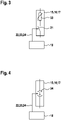
- Fig. 3 is a block diagram of a discharging unit 15, 16, 17 of a second comparative example, corresponding to the first example.
- a thermistor 33 with a positive temperature coefficient (PTC) is provided in place of the resistor 20 .
- Fig. 4 is a block diagram wherein each discharging unit 15, 16, 17 of figure 1 is implemented in accordance with the present invention.
- a current drain 34 controllable by the control signals 22, 23, 24 is provided in place of the resistor 20 and the switching element 21 .
- the current drain 34 pulls a respective discharging current 27 from the smoothing capacitor 12.
- the current drain 34 pulls no current or a current nearby during the off-time.
- the current drain 34 is realized by a voltage-controlled current source circuit connected in a direction of the desired discharging current 27.
- each discharge current 27 is reduced instead of being suppressed.
- An average value of the reduced discharge current 27 is only 10% of an average value of the discharge current 27 during the on-time 29.
- the reduction is realized by interconnecting the switching element 21 such that it connects a further resistor in series with the resistor 20 or disconnects a further resistor connected in parallel to the resistor 20.
- the reduction is realized by controlling the current drain 34 to pull the discharging current 27 with the lower average value.
- the on-times 29 are overlapping, therein avoiding the dead time 31.
- control unit 7 and the control unit 18 may be realized integrally in the same piece of hardware, e.g. by different sections of software.
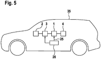
- Fig. 5 is a schematic diagram of a vehicle 35, comprising an energy source 2, a contactor 3, an electric power converter 1 according to any of the aforementioned embodiments and an electric machine 4 configured to drive the vehicle 35, Furthermore the vehicle 35 comprises a controller 26, which is configured to provide the external signal 25 and to open the contactor 3.
Landscapes
- Engineering & Computer Science (AREA)
- Power Engineering (AREA)
- Life Sciences & Earth Sciences (AREA)
- Sustainable Development (AREA)
- Sustainable Energy (AREA)
- Transportation (AREA)
- Mechanical Engineering (AREA)
- Inverter Devices (AREA)
Claims (14)
- Gleichstromverbindungsstreckenschaltung (5) für einen Umsetzer (1) elektrischer Leistung, die Folgendes umfasst:- einen Glättungskondensator (12),- wenigstens zwei Entladungseinheiten (15, 16, 17), die parallelgeschaltet sind und jeweils eine Stromsenke (34), die durch eine gesteuerte Stromquelle, die mit dem Glättungskondensator (12) verbunden ist, verwirklicht ist, enthalten, um von dem Glättungskondensator (12) über die Entladungseinheit (15, 16, 17) einen Entladungsstrom (27) zu ziehen, und- eine Steuereinheit (18), die konfiguriert ist, Steuersignale (22, 23, 24) bereitzustellen, wovon jedes- die Stromsenke (34) einer Entladungseinheit (15, 16, 17) steuert,- die Entladungseinheit (15, 16, 17) veranlasst, einen Fluss des Entladungsstroms (27) während einer Einschaltzeit (29) zuzulassen und den Fluss des Entladungsstroms (27) während einer Ausschaltzeit (30) zu verringern, und- die Stromsenke (34) während der Ausschaltzeit (30) steuert, um den Entladungsstroms durch Ziehen eines konstanten Stroms, der niedriger als der während der Einschaltzeit (29) gezogene Strom ist, zu verringern,
wobei die Einschaltzeiten (29) einen gegenseitigen zeitlichen Versatz aufweisen. - Gleichstromverbindungsstreckenschaltung nach Anspruch 1, wobei die Stromsenke (34) durch das Steuersignal (22, 23, 24) gesteuert wird, um während der Einschaltzeit (29) einen Strom zu ziehen.
- Gleichstromverbindungsstreckenschaltung nach Anspruch 2, wobei der Strom konstant ist.
- Gleichstromverbindungsstreckenschaltung nach einem der vorhergehenden Ansprüche, wobei der Durchschnittswert des Entladungsstroms (27) während der Ausschaltzeit (30) höchstens 50 %, vorzugsweise höchstens 25 % und stärker bevorzugt höchstens 10 % eines Durchschnittswerts des Entladungsstroms während der Einschaltzeit (29) beträgt.
- Gleichstromverbindungsstreckenschaltung nach einem der vorhergehenden Ansprüche, wobei die Steuereinheit (18) konfiguriert ist, die Steuersignale (22, 23, 24) periodisch bereitzustellen.
- Gleichstromverbindungsstreckenschaltung nach Anspruch 5, wobei eine Periode jedes Steuersignals (22, 23, 24) höchstens eine Einschaltzeit (29) enthält.
- Gleichstromverbindungsstreckenschaltung nach einem der vorhergehenden Ansprüche, wobei die Einschaltzeiten der Steuersignale (22, 23, 24), die für verschiedene Entladungseinheiten (15, 16, 17) bereitgestellt werden, keine Überlappung aufweisen oder miteinander überlappen.
- Gleichstromverbindungsstreckenschaltung nach einem der vorhergehenden Ansprüche, wobei die Steuersignale (22, 23, 24) die Entladungseinheiten (15, 16, 17) dazu veranlassen, den Fluss des Entladungsstroms (27) nacheinander zuzulassen.
- Gleichstromverbindungsstreckenschaltung nach Anspruch 8, wobei eine Zeitspanne (31) zwischen aufeinanderfolgenden Einschaltzeiten (29) gleich ist.
- Gleichstromverbindungsstreckenschaltung nach einem der vorhergehenden Ansprüche, die eine Wärmesenke (19) enthält, an der die Entladungseinheiten (15, 16, 17) wenigstens teilweise befestigt sind und miteinander thermisch gekoppelt sind.
- Umsetzer (1) elektrischer Leistung für ein Fahrzeug (35), der eine Gleichstromverbindungsstreckenschaltung (5) nach einem der Ansprüche 1 bis 10 enthält.
- Umsetzer elektrischer Leistung nach Anspruch 11, wobei der Umsetzer (1) elektrischer Leistung ein Wechselrichter ist.
- Fahrzeug (35), das eine elektrische Maschine (4), die konfiguriert ist, das Fahrzeug (35) anzutreiben, und einen Umsetzer (1) elektrischer Leistung nach Anspruch 11 oder 12, der konfiguriert ist, die elektrische Maschine (4) zu versorgen, enthält.
- Verfahren zum Steuern einer Gleichstromverbindungsstreckenschaltung (5) eines Umsetzers (1) elektrischer Leistung, die Folgendes umfasst:- einen Glättungskondensator (12) und- wenigstens zwei Entladungseinheiten (15, 16, 17) die parallelgeschaltet sind und jeweils eine Stromsenke (34), die durch eine gesteuerte Stromquelle, die mit dem Glättungskondensator (12) verbunden ist, verwirklicht ist, enthalten, um von dem Glättungskondensator (12) über die Entladungseinheit (15, 16, 17) einen Entladungsstrom (27) zu ziehen, wobei Steuersignale (22, 23, 24) bereitgestellt werden, die jeweils- die Stromsenke (34) einer Entladungseinheit (15, 16, 17) steuern,- die Entladungseinheit (15, 16, 17) veranlassen, einen Fluss des Entladungsstroms (27) während einer Einschaltzeit (29) zuzulassen und den Fluss des Entladungsstroms (27) während einer Ausschaltzeit (30) zu verringern, und- die Stromsenke (34) während der Ausschaltzeit (30) steuern, um den Entladungsstrom durch Ziehen eines konstanten Stroms, der niedriger als der während der Einschaltzeit (29) gezogene Strom ist, zu verringern,
wobei die Einschaltzeiten (29) einen gegenseitigen zeitlichen Versatz aufweisen.
Priority Applications (1)
| Application Number | Priority Date | Filing Date | Title |
|---|---|---|---|
| EP17205441.3A EP3496251B1 (de) | 2017-12-05 | 2017-12-05 | Gleichstromzwischenkreis, stromwandler, fahrzeug und verfahren zur steuerung eines gleichstromzwischenkreises eines stromwandlers |
Applications Claiming Priority (1)
| Application Number | Priority Date | Filing Date | Title |
|---|---|---|---|
| EP17205441.3A EP3496251B1 (de) | 2017-12-05 | 2017-12-05 | Gleichstromzwischenkreis, stromwandler, fahrzeug und verfahren zur steuerung eines gleichstromzwischenkreises eines stromwandlers |
Publications (2)
| Publication Number | Publication Date |
|---|---|
| EP3496251A1 EP3496251A1 (de) | 2019-06-12 |
| EP3496251B1 true EP3496251B1 (de) | 2022-11-09 |
Family
ID=60582453
Family Applications (1)
| Application Number | Title | Priority Date | Filing Date |
|---|---|---|---|
| EP17205441.3A Active EP3496251B1 (de) | 2017-12-05 | 2017-12-05 | Gleichstromzwischenkreis, stromwandler, fahrzeug und verfahren zur steuerung eines gleichstromzwischenkreises eines stromwandlers |
Country Status (1)
| Country | Link |
|---|---|
| EP (1) | EP3496251B1 (de) |
Families Citing this family (4)
| Publication number | Priority date | Publication date | Assignee | Title |
|---|---|---|---|---|
| EP3840202A1 (de) * | 2019-12-20 | 2021-06-23 | Panasonic Intellectual Property Management Co., Ltd. | Verfahren, system und vorrichtung zum entladen von gleichstromzwischenkreiskondensatoren in stromverteilungseinheiten |
| EP3843253A1 (de) * | 2019-12-27 | 2021-06-30 | Solaredge Technologies Ltd. | Entladeverfahren und -vorrichtung |
| EP3920391A1 (de) * | 2020-06-04 | 2021-12-08 | Schaffner EMV AG | Emi filter |
| DE102021202914B3 (de) * | 2021-03-25 | 2022-06-15 | Volkswagen Aktiengesellschaft | Pulswechselrichteranordnung und Verfahren zum Betreiben einer Pulswechselrichteranordnung |
Citations (3)
| Publication number | Priority date | Publication date | Assignee | Title |
|---|---|---|---|---|
| JPH10224902A (ja) * | 1997-02-04 | 1998-08-21 | Nissan Motor Co Ltd | 電気自動車のモーター駆動制御装置 |
| DE102013223538A1 (de) * | 2013-11-19 | 2014-10-23 | Siemens Aktiengesellschaft | Schaltungsanordnung und Verfahren zum Erzeugen einer Zwischenkreisspannung für einen Wechselrichter |
| US20150251542A1 (en) * | 2014-03-06 | 2015-09-10 | Ford Global Technologies, Llc | Capacitor precharging and capacitance/resistance measurement in electric vehicle drive system |
Family Cites Families (4)
| Publication number | Priority date | Publication date | Assignee | Title |
|---|---|---|---|---|
| JP5094797B2 (ja) * | 2009-08-07 | 2012-12-12 | 日立オートモティブシステムズ株式会社 | 直流電源平滑用コンデンサーの放電回路 |
| FR2968477B1 (fr) * | 2010-12-06 | 2014-10-24 | Schneider Toshiba Inverter | Dispositif de decharge rapide d'un condensateur |
| JP5670398B2 (ja) * | 2012-09-10 | 2015-02-18 | ファナック株式会社 | 少なくとも2つの抵抗放電手段を有するモータ制御装置 |
| WO2017108046A1 (en) * | 2015-12-22 | 2017-06-29 | Vestas Wind Systems A/S | Power dissipation system and control method for a wind turbine power converter |
-
2017
- 2017-12-05 EP EP17205441.3A patent/EP3496251B1/de active Active
Patent Citations (3)
| Publication number | Priority date | Publication date | Assignee | Title |
|---|---|---|---|---|
| JPH10224902A (ja) * | 1997-02-04 | 1998-08-21 | Nissan Motor Co Ltd | 電気自動車のモーター駆動制御装置 |
| DE102013223538A1 (de) * | 2013-11-19 | 2014-10-23 | Siemens Aktiengesellschaft | Schaltungsanordnung und Verfahren zum Erzeugen einer Zwischenkreisspannung für einen Wechselrichter |
| US20150251542A1 (en) * | 2014-03-06 | 2015-09-10 | Ford Global Technologies, Llc | Capacitor precharging and capacitance/resistance measurement in electric vehicle drive system |
Also Published As
| Publication number | Publication date |
|---|---|
| EP3496251A1 (de) | 2019-06-12 |
Similar Documents
| Publication | Publication Date | Title |
|---|---|---|
| US12021444B2 (en) | System and method for compact motor control with redundant power structures | |
| EP2587656B1 (de) | Integrierter regenerativer Wechselstromantrieb mit Zuvoraufladung mittels Halbleiter | |
| US8432715B2 (en) | Power conversion control apparatus for power conversion circuit including high-side and low-side switching elements and power storage device | |
| US12090863B2 (en) | Discharge apparatus for an electrical drive arrangement of a vehicle and electrical drive arrangement comprising the discharge apparatus | |
| EP2737605B1 (de) | Doppelter aufwärtswandler für ein usv-system | |
| KR102768100B1 (ko) | 인버터 시스템 시동 방법 및 인버터 시스템 | |
| US11355939B2 (en) | Device and process for discharging an intermediate circuit capacitor and process for producing a device for discharging an intermediate circuit capacitor | |
| US9350268B2 (en) | Control device for semiconductor switch on an inverter and method for the actuation of an inverter | |
| US12525874B2 (en) | Methods of starting power converter systems, and power converter systems | |
| US12255548B2 (en) | Method for actively discharging an electrical energy storage device, control device, electrical circuit device and motor vehicle | |
| EP2562021B1 (de) | System und Verfahren zur Steuerung regenerativer elektrischer Energie | |
| KR101698401B1 (ko) | 냉각 부재를 포함하는 에너지 저장 장치, 및 에너지 저장 셀의 냉각 방법 | |
| CN107046273B (zh) | 电力系统 | |
| KR20130090816A (ko) | 중간 회로를 가진 전력 변환기용 회로 장치 및 전력 변환기 동작 방법 | |
| AU2013260082A1 (en) | Method and apparatus for controlling thermal cycling | |
| US20030165071A1 (en) | Open-loop and closed-loop control method for a three-point converter with active clamped switches, and apparatus for this purpose | |
| EP3496251A1 (de) | Gleichstromzwischenkreis, stromwandler, fahrzeug und verfahren zur steuerung eines gleichstromzwischenkreises eines stromwandlers | |
| CN103563162A (zh) | 具有加热装置的能量存储装置和用于预热能量存储装置的能量单元的方法 | |
| KR101801780B1 (ko) | 고효율 전력 변환 시스템 | |
| EP2944013B1 (de) | Stromversorgungssystem | |
| US20200153271A1 (en) | Integrated Power Supply System for Auxiliary Services for Power Converters | |
| EP4496221A1 (de) | Festkörperleistungsregler, leistungsverwaltungssystem und leistungswandler | |
| US20240339947A1 (en) | Method for operating a power supply circuit in an inverter for driving an electric machine, computing unit, power supply circuit in an inverter and inverter | |
| KR101646402B1 (ko) | 컨버터의 과온 보호 장치 및 방법 | |
| JP2024052294A (ja) | パワー半導体素子の駆動装置、電力変換装置 |
Legal Events
| Date | Code | Title | Description |
|---|---|---|---|
| PUAI | Public reference made under article 153(3) epc to a published international application that has entered the european phase |
Free format text: ORIGINAL CODE: 0009012 |
|
| STAA | Information on the status of an ep patent application or granted ep patent |
Free format text: STATUS: THE APPLICATION HAS BEEN PUBLISHED |
|
| AK | Designated contracting states |
Kind code of ref document: A1 Designated state(s): AL AT BE BG CH CY CZ DE DK EE ES FI FR GB GR HR HU IE IS IT LI LT LU LV MC MK MT NL NO PL PT RO RS SE SI SK SM TR |
|
| AX | Request for extension of the european patent |
Extension state: BA ME |
|
| STAA | Information on the status of an ep patent application or granted ep patent |
Free format text: STATUS: REQUEST FOR EXAMINATION WAS MADE |
|
| 17P | Request for examination filed |
Effective date: 20191210 |
|
| RBV | Designated contracting states (corrected) |
Designated state(s): AL AT BE BG CH CY CZ DE DK EE ES FI FR GB GR HR HU IE IS IT LI LT LU LV MC MK MT NL NO PL PT RO RS SE SI SK SM TR |
|
| STAA | Information on the status of an ep patent application or granted ep patent |
Free format text: STATUS: EXAMINATION IS IN PROGRESS |
|
| 17Q | First examination report despatched |
Effective date: 20200129 |
|
| GRAP | Despatch of communication of intention to grant a patent |
Free format text: ORIGINAL CODE: EPIDOSNIGR1 |
|
| STAA | Information on the status of an ep patent application or granted ep patent |
Free format text: STATUS: GRANT OF PATENT IS INTENDED |
|
| INTG | Intention to grant announced |
Effective date: 20211220 |
|
| GRAJ | Information related to disapproval of communication of intention to grant by the applicant or resumption of examination proceedings by the epo deleted |
Free format text: ORIGINAL CODE: EPIDOSDIGR1 |
|
| STAA | Information on the status of an ep patent application or granted ep patent |
Free format text: STATUS: EXAMINATION IS IN PROGRESS |
|
| GRAP | Despatch of communication of intention to grant a patent |
Free format text: ORIGINAL CODE: EPIDOSNIGR1 |
|
| STAA | Information on the status of an ep patent application or granted ep patent |
Free format text: STATUS: GRANT OF PATENT IS INTENDED |
|
| INTC | Intention to grant announced (deleted) | ||
| INTG | Intention to grant announced |
Effective date: 20220506 |
|
| GRAS | Grant fee paid |
Free format text: ORIGINAL CODE: EPIDOSNIGR3 |
|
| RAP3 | Party data changed (applicant data changed or rights of an application transferred) |
Owner name: VALEO EAUTOMOTIVE GERMANY GMBH |
|
| GRAA | (expected) grant |
Free format text: ORIGINAL CODE: 0009210 |
|
| STAA | Information on the status of an ep patent application or granted ep patent |
Free format text: STATUS: THE PATENT HAS BEEN GRANTED |
|
| AK | Designated contracting states |
Kind code of ref document: B1 Designated state(s): AL AT BE BG CH CY CZ DE DK EE ES FI FR GB GR HR HU IE IS IT LI LT LU LV MC MK MT NL NO PL PT RO RS SE SI SK SM TR |
|
| REG | Reference to a national code |
Ref country code: GB Ref legal event code: FG4D |
|
| REG | Reference to a national code |
Ref country code: CH Ref legal event code: EP Ref country code: AT Ref legal event code: REF Ref document number: 1531011 Country of ref document: AT Kind code of ref document: T Effective date: 20221115 |
|
| REG | Reference to a national code |
Ref country code: IE Ref legal event code: FG4D |
|
| REG | Reference to a national code |
Ref country code: DE Ref legal event code: R096 Ref document number: 602017063484 Country of ref document: DE |
|
| REG | Reference to a national code |
Ref country code: LT Ref legal event code: MG9D |
|
| REG | Reference to a national code |
Ref country code: NL Ref legal event code: MP Effective date: 20221109 |
|
| REG | Reference to a national code |
Ref country code: AT Ref legal event code: MK05 Ref document number: 1531011 Country of ref document: AT Kind code of ref document: T Effective date: 20221109 |
|
| PG25 | Lapsed in a contracting state [announced via postgrant information from national office to epo] |
Ref country code: SE Free format text: LAPSE BECAUSE OF FAILURE TO SUBMIT A TRANSLATION OF THE DESCRIPTION OR TO PAY THE FEE WITHIN THE PRESCRIBED TIME-LIMIT Effective date: 20221109 Ref country code: PT Free format text: LAPSE BECAUSE OF FAILURE TO SUBMIT A TRANSLATION OF THE DESCRIPTION OR TO PAY THE FEE WITHIN THE PRESCRIBED TIME-LIMIT Effective date: 20230309 Ref country code: NO Free format text: LAPSE BECAUSE OF FAILURE TO SUBMIT A TRANSLATION OF THE DESCRIPTION OR TO PAY THE FEE WITHIN THE PRESCRIBED TIME-LIMIT Effective date: 20230209 Ref country code: LT Free format text: LAPSE BECAUSE OF FAILURE TO SUBMIT A TRANSLATION OF THE DESCRIPTION OR TO PAY THE FEE WITHIN THE PRESCRIBED TIME-LIMIT Effective date: 20221109 Ref country code: FI Free format text: LAPSE BECAUSE OF FAILURE TO SUBMIT A TRANSLATION OF THE DESCRIPTION OR TO PAY THE FEE WITHIN THE PRESCRIBED TIME-LIMIT Effective date: 20221109 Ref country code: ES Free format text: LAPSE BECAUSE OF FAILURE TO SUBMIT A TRANSLATION OF THE DESCRIPTION OR TO PAY THE FEE WITHIN THE PRESCRIBED TIME-LIMIT Effective date: 20221109 Ref country code: AT Free format text: LAPSE BECAUSE OF FAILURE TO SUBMIT A TRANSLATION OF THE DESCRIPTION OR TO PAY THE FEE WITHIN THE PRESCRIBED TIME-LIMIT Effective date: 20221109 |
|
| PG25 | Lapsed in a contracting state [announced via postgrant information from national office to epo] |
Ref country code: RS Free format text: LAPSE BECAUSE OF FAILURE TO SUBMIT A TRANSLATION OF THE DESCRIPTION OR TO PAY THE FEE WITHIN THE PRESCRIBED TIME-LIMIT Effective date: 20221109 Ref country code: PL Free format text: LAPSE BECAUSE OF FAILURE TO SUBMIT A TRANSLATION OF THE DESCRIPTION OR TO PAY THE FEE WITHIN THE PRESCRIBED TIME-LIMIT Effective date: 20221109 Ref country code: LV Free format text: LAPSE BECAUSE OF FAILURE TO SUBMIT A TRANSLATION OF THE DESCRIPTION OR TO PAY THE FEE WITHIN THE PRESCRIBED TIME-LIMIT Effective date: 20221109 Ref country code: IS Free format text: LAPSE BECAUSE OF FAILURE TO SUBMIT A TRANSLATION OF THE DESCRIPTION OR TO PAY THE FEE WITHIN THE PRESCRIBED TIME-LIMIT Effective date: 20230309 Ref country code: HR Free format text: LAPSE BECAUSE OF FAILURE TO SUBMIT A TRANSLATION OF THE DESCRIPTION OR TO PAY THE FEE WITHIN THE PRESCRIBED TIME-LIMIT Effective date: 20221109 Ref country code: GR Free format text: LAPSE BECAUSE OF FAILURE TO SUBMIT A TRANSLATION OF THE DESCRIPTION OR TO PAY THE FEE WITHIN THE PRESCRIBED TIME-LIMIT Effective date: 20230210 |
|
| PG25 | Lapsed in a contracting state [announced via postgrant information from national office to epo] |
Ref country code: NL Free format text: LAPSE BECAUSE OF FAILURE TO SUBMIT A TRANSLATION OF THE DESCRIPTION OR TO PAY THE FEE WITHIN THE PRESCRIBED TIME-LIMIT Effective date: 20221109 |
|
| P01 | Opt-out of the competence of the unified patent court (upc) registered |
Effective date: 20230528 |
|
| PG25 | Lapsed in a contracting state [announced via postgrant information from national office to epo] |
Ref country code: SM Free format text: LAPSE BECAUSE OF FAILURE TO SUBMIT A TRANSLATION OF THE DESCRIPTION OR TO PAY THE FEE WITHIN THE PRESCRIBED TIME-LIMIT Effective date: 20221109 Ref country code: RO Free format text: LAPSE BECAUSE OF FAILURE TO SUBMIT A TRANSLATION OF THE DESCRIPTION OR TO PAY THE FEE WITHIN THE PRESCRIBED TIME-LIMIT Effective date: 20221109 Ref country code: EE Free format text: LAPSE BECAUSE OF FAILURE TO SUBMIT A TRANSLATION OF THE DESCRIPTION OR TO PAY THE FEE WITHIN THE PRESCRIBED TIME-LIMIT Effective date: 20221109 Ref country code: DK Free format text: LAPSE BECAUSE OF FAILURE TO SUBMIT A TRANSLATION OF THE DESCRIPTION OR TO PAY THE FEE WITHIN THE PRESCRIBED TIME-LIMIT Effective date: 20221109 Ref country code: CZ Free format text: LAPSE BECAUSE OF FAILURE TO SUBMIT A TRANSLATION OF THE DESCRIPTION OR TO PAY THE FEE WITHIN THE PRESCRIBED TIME-LIMIT Effective date: 20221109 |
|
| REG | Reference to a national code |
Ref country code: CH Ref legal event code: PL |
|
| REG | Reference to a national code |
Ref country code: DE Ref legal event code: R097 Ref document number: 602017063484 Country of ref document: DE |
|
| REG | Reference to a national code |
Ref country code: BE Ref legal event code: MM Effective date: 20221231 |
|
| PG25 | Lapsed in a contracting state [announced via postgrant information from national office to epo] |
Ref country code: SK Free format text: LAPSE BECAUSE OF FAILURE TO SUBMIT A TRANSLATION OF THE DESCRIPTION OR TO PAY THE FEE WITHIN THE PRESCRIBED TIME-LIMIT Effective date: 20221109 Ref country code: LU Free format text: LAPSE BECAUSE OF NON-PAYMENT OF DUE FEES Effective date: 20221205 Ref country code: AL Free format text: LAPSE BECAUSE OF FAILURE TO SUBMIT A TRANSLATION OF THE DESCRIPTION OR TO PAY THE FEE WITHIN THE PRESCRIBED TIME-LIMIT Effective date: 20221109 |
|
| PLBE | No opposition filed within time limit |
Free format text: ORIGINAL CODE: 0009261 |
|
| STAA | Information on the status of an ep patent application or granted ep patent |
Free format text: STATUS: NO OPPOSITION FILED WITHIN TIME LIMIT |
|
| 26N | No opposition filed |
Effective date: 20230810 |
|
| GBPC | Gb: european patent ceased through non-payment of renewal fee |
Effective date: 20230209 |
|
| PG25 | Lapsed in a contracting state [announced via postgrant information from national office to epo] |
Ref country code: LI Free format text: LAPSE BECAUSE OF NON-PAYMENT OF DUE FEES Effective date: 20221231 Ref country code: IE Free format text: LAPSE BECAUSE OF NON-PAYMENT OF DUE FEES Effective date: 20221205 Ref country code: CH Free format text: LAPSE BECAUSE OF NON-PAYMENT OF DUE FEES Effective date: 20221231 |
|
| PG25 | Lapsed in a contracting state [announced via postgrant information from national office to epo] |
Ref country code: SI Free format text: LAPSE BECAUSE OF FAILURE TO SUBMIT A TRANSLATION OF THE DESCRIPTION OR TO PAY THE FEE WITHIN THE PRESCRIBED TIME-LIMIT Effective date: 20221109 Ref country code: BE Free format text: LAPSE BECAUSE OF NON-PAYMENT OF DUE FEES Effective date: 20221231 |
|
| PG25 | Lapsed in a contracting state [announced via postgrant information from national office to epo] |
Ref country code: GB Free format text: LAPSE BECAUSE OF NON-PAYMENT OF DUE FEES Effective date: 20230209 |
|
| PG25 | Lapsed in a contracting state [announced via postgrant information from national office to epo] |
Ref country code: GB Free format text: LAPSE BECAUSE OF NON-PAYMENT OF DUE FEES Effective date: 20230209 |
|
| PG25 | Lapsed in a contracting state [announced via postgrant information from national office to epo] |
Ref country code: HU Free format text: LAPSE BECAUSE OF FAILURE TO SUBMIT A TRANSLATION OF THE DESCRIPTION OR TO PAY THE FEE WITHIN THE PRESCRIBED TIME-LIMIT; INVALID AB INITIO Effective date: 20171205 |
|
| PG25 | Lapsed in a contracting state [announced via postgrant information from national office to epo] |
Ref country code: CY Free format text: LAPSE BECAUSE OF FAILURE TO SUBMIT A TRANSLATION OF THE DESCRIPTION OR TO PAY THE FEE WITHIN THE PRESCRIBED TIME-LIMIT Effective date: 20221109 |
|
| PG25 | Lapsed in a contracting state [announced via postgrant information from national office to epo] |
Ref country code: MK Free format text: LAPSE BECAUSE OF FAILURE TO SUBMIT A TRANSLATION OF THE DESCRIPTION OR TO PAY THE FEE WITHIN THE PRESCRIBED TIME-LIMIT Effective date: 20221109 Ref country code: IT Free format text: LAPSE BECAUSE OF FAILURE TO SUBMIT A TRANSLATION OF THE DESCRIPTION OR TO PAY THE FEE WITHIN THE PRESCRIBED TIME-LIMIT Effective date: 20221109 |
|
| PG25 | Lapsed in a contracting state [announced via postgrant information from national office to epo] |
Ref country code: MC Free format text: LAPSE BECAUSE OF FAILURE TO SUBMIT A TRANSLATION OF THE DESCRIPTION OR TO PAY THE FEE WITHIN THE PRESCRIBED TIME-LIMIT Effective date: 20221109 |
|
| PG25 | Lapsed in a contracting state [announced via postgrant information from national office to epo] |
Ref country code: MC Free format text: LAPSE BECAUSE OF FAILURE TO SUBMIT A TRANSLATION OF THE DESCRIPTION OR TO PAY THE FEE WITHIN THE PRESCRIBED TIME-LIMIT Effective date: 20221109 |
|
| PG25 | Lapsed in a contracting state [announced via postgrant information from national office to epo] |
Ref country code: BG Free format text: LAPSE BECAUSE OF FAILURE TO SUBMIT A TRANSLATION OF THE DESCRIPTION OR TO PAY THE FEE WITHIN THE PRESCRIBED TIME-LIMIT Effective date: 20221109 |
|
| PG25 | Lapsed in a contracting state [announced via postgrant information from national office to epo] |
Ref country code: MT Free format text: LAPSE BECAUSE OF FAILURE TO SUBMIT A TRANSLATION OF THE DESCRIPTION OR TO PAY THE FEE WITHIN THE PRESCRIBED TIME-LIMIT Effective date: 20221109 |
|
| PG25 | Lapsed in a contracting state [announced via postgrant information from national office to epo] |
Ref country code: TR Free format text: LAPSE BECAUSE OF FAILURE TO SUBMIT A TRANSLATION OF THE DESCRIPTION OR TO PAY THE FEE WITHIN THE PRESCRIBED TIME-LIMIT Effective date: 20221109 |
|
| PGFP | Annual fee paid to national office [announced via postgrant information from national office to epo] |
Ref country code: FR Payment date: 20251230 Year of fee payment: 9 |
|
| PGFP | Annual fee paid to national office [announced via postgrant information from national office to epo] |
Ref country code: DE Payment date: 20251231 Year of fee payment: 9 |