EP3496344A1 - Verfahren und vorrichtungen zum senden und empfangen von diensten und netzwerksystem - Google Patents
Verfahren und vorrichtungen zum senden und empfangen von diensten und netzwerksystem Download PDFInfo
- Publication number
- EP3496344A1 EP3496344A1 EP17842907.2A EP17842907A EP3496344A1 EP 3496344 A1 EP3496344 A1 EP 3496344A1 EP 17842907 A EP17842907 A EP 17842907A EP 3496344 A1 EP3496344 A1 EP 3496344A1
- Authority
- EP
- European Patent Office
- Prior art keywords
- data stream
- segment
- unit
- data
- idle
- Prior art date
- Legal status (The legal status is an assumption and is not a legal conclusion. Google has not performed a legal analysis and makes no representation as to the accuracy of the status listed.)
- Granted
Links
Images










Classifications
-
- H—ELECTRICITY
- H04—ELECTRIC COMMUNICATION TECHNIQUE
- H04J—MULTIPLEX COMMUNICATION
- H04J3/00—Time-division multiplex systems
- H04J3/16—Time-division multiplex systems in which the time allocation to individual channels within a transmission cycle is variable, e.g. to accommodate varying complexity of signals, to vary number of channels transmitted
- H04J3/1605—Fixed allocated frame structures
- H04J3/1652—Optical Transport Network [OTN]
- H04J3/1658—Optical Transport Network [OTN] carrying packets or ATM cells
-
- H—ELECTRICITY
- H04—ELECTRIC COMMUNICATION TECHNIQUE
- H04L—TRANSMISSION OF DIGITAL INFORMATION, e.g. TELEGRAPHIC COMMUNICATION
- H04L7/00—Arrangements for synchronising receiver with transmitter
- H04L7/0008—Synchronisation information channels, e.g. clock distribution lines
-
- H—ELECTRICITY
- H04—ELECTRIC COMMUNICATION TECHNIQUE
- H04J—MULTIPLEX COMMUNICATION
- H04J3/00—Time-division multiplex systems
- H04J3/16—Time-division multiplex systems in which the time allocation to individual channels within a transmission cycle is variable, e.g. to accommodate varying complexity of signals, to vary number of channels transmitted
- H04J3/1605—Fixed allocated frame structures
- H04J3/1611—Synchronous digital hierarchy [SDH] or SONET
-
- H—ELECTRICITY
- H04—ELECTRIC COMMUNICATION TECHNIQUE
- H04L—TRANSMISSION OF DIGITAL INFORMATION, e.g. TELEGRAPHIC COMMUNICATION
- H04L7/00—Arrangements for synchronising receiver with transmitter
-
- H—ELECTRICITY
- H04—ELECTRIC COMMUNICATION TECHNIQUE
- H04J—MULTIPLEX COMMUNICATION
- H04J3/00—Time-division multiplex systems
- H04J3/02—Details
- H04J3/06—Synchronising arrangements
- H04J3/0635—Clock or time synchronisation in a network
- H04J3/0638—Clock or time synchronisation among nodes; Internode synchronisation
- H04J3/0658—Clock or time synchronisation among packet nodes
-
- H—ELECTRICITY
- H04—ELECTRIC COMMUNICATION TECHNIQUE
- H04J—MULTIPLEX COMMUNICATION
- H04J3/00—Time-division multiplex systems
- H04J3/16—Time-division multiplex systems in which the time allocation to individual channels within a transmission cycle is variable, e.g. to accommodate varying complexity of signals, to vary number of channels transmitted
- H04J3/1605—Fixed allocated frame structures
- H04J3/1652—Optical Transport Network [OTN]
-
- H—ELECTRICITY
- H04—ELECTRIC COMMUNICATION TECHNIQUE
- H04L—TRANSMISSION OF DIGITAL INFORMATION, e.g. TELEGRAPHIC COMMUNICATION
- H04L49/00—Packet switching elements
- H04L49/35—Switches specially adapted for specific applications
- H04L49/351—Switches specially adapted for specific applications for local area network [LAN], e.g. Ethernet switches
- H04L49/352—Gigabit ethernet switching [GBPS]
-
- H—ELECTRICITY
- H04—ELECTRIC COMMUNICATION TECHNIQUE
- H04J—MULTIPLEX COMMUNICATION
- H04J2203/00—Aspects of optical multiplex systems other than those covered by H04J14/05 and H04J14/07
- H04J2203/0001—Provisions for broadband connections in integrated services digital network using frames of the Optical Transport Network [OTN] or using synchronous transfer mode [STM], e.g. SONET, SDH
- H04J2203/0073—Services, e.g. multimedia, GOS, QOS
- H04J2203/0082—Interaction of SDH with non-ATM protocols
- H04J2203/0085—Support of Ethernet
Definitions
- the present invention relates to the communications field, and in particular, to a method and an apparatus for sending a service, a method and an apparatus for receiving a service, and a network system.
- the flexible Ethernet (FlexE) combines some technical features of the Ethernet and a transport network (for example, an optical transport network (Optical Transport Network, OTN), and a synchronous digital hierarchy (Synchronous Digital Hierarchy, SDH)), and is an important milestone in the evolution of an Ethernet technology.
- a transport network for example, an optical transport network (Optical Transport Network, OTN), and a synchronous digital hierarchy (Synchronous Digital Hierarchy, SDH)
- OTN optical Transport Network
- SDH Synchronous Digital Hierarchy
- Ethernet physical interfaces show virtualization characteristics.
- a plurality of Ethernet physical interfaces may be bonded together, to support several virtual logical ports.
- a 400-gigabit (400 Gigabit, 400G) flexible Ethernet physical interface group obtained by bonding four 100-gigabit Ethernet (100 Gigabit Ethernet, 100GE) physical interfaces may support several logical ports.
- the Ethernet physical interface is an asynchronous communications interface, and is allowed to have a clock frequency difference of ⁇ 100 ppm (one ten-thousandth). For example, in 10GE, for two physical interfaces whose nominal bandwidths are 10 G, one bandwidth may be one ten-thousandth larger than the nominal value, and the other bandwidth is one ten-thousandth smaller than the nominal value, that is, 10G ⁇ (1+0.0001) and 10G ⁇ (1-0.0001). A clock frequency at the logical port inherits a clock frequency characteristic on the physical interface, and therefore the logical port also has a difference of 100 ppm.
- FIG. 1 is a schematic diagram of service transport in the flexible Ethernet in the prior art. As shown in FIG. 1 , when a service between customer devices Ca and Cb is borne by using flexible Ethernet devices Pa, Pb, and Pc, the Pa, the Pb, and the Pc needs to perform idle-unit insertion or deletion.
- idle-code-block insertion or deletion causes loss of a clock frequency and time phase information of the service, that is, the clock frequency and the time phase information of the service cannot be transparently transported, and consequently the clock frequency and the time phase cannot be synchronized between a source network device and a sink network device of the service.
- embodiments of the present invention provide a method and an apparatus for sending a service, a method and an apparatus for receiving a service, and a network system, to resolve the following problem: Because a clock frequency and time phase information of a service cannot be transparently transported in the flexible Ethernet, the clock frequency and the time phase cannot be synchronized between a source network device and a sink network device of the service.
- an embodiment of the present invention provides a method for sending a service, including: A transmit end device obtains an original data stream; next, the transmit end device inserts a quantity mark k into the original data stream, to generate a first data stream, where the quantity mark k is used to identify a quantity of first data units in the original data stream, and k is greater than or equal to 0; and finally, the transmit end device sends the first data stream.
- the quantity mark k is inserted into the original data stream, and is used to identify the quantity of first data units in the original data stream.
- a receive end device can recover, according to the quantity mark k, the original data stream from a data stream on which idle-unit insertion or deletion is performed, to recover a clock frequency and time phase information of the original data stream, so that a clock frequency and time phase information of a service are transparently transported.
- the inserting a quantity mark k into the original data stream includes: obtaining a first segment of data stream from the original data stream, and determining a quantity of first data units in the first segment of data stream; and inserting the quantity mark k at a first location in the first segment of data stream, where a value of the quantity mark k is equal to the quantity of first data units in the first segment of data stream, and the first location is a location of a data unit that can be used to carry the quantity mark k.
- the original data stream is divided into segments, so that the quantity mark k can be inserted by segment.
- the first data unit includes all data units in the first segment of data stream, and k is an integer greater than 0.
- an idle unit may be inserted or deleted, and this causes a change of a quantity of data units in the original data stream. Therefore, a quantity of all data units in the first segment of data stream in the original data stream can be identified by using the quantity mark k.
- the first data unit is an idle unit in the first segment of data stream
- k is an integer greater than or equal to 0.
- a quantity of idle units in the first segment of data stream in the original data stream can be identified by using the quantity mark k.
- the obtaining a first segment of data stream from the original data stream includes: identifying a start unit in the original data stream, and determining a location of the start unit as the first location.
- the start unit may be a code block unit having a fixed pattern, that is, having redundant information, and therefore can be used to carry the quantity mark k.
- the location of the start unit may be further determined as a boundary of the first segment of data stream. That is, the start unit may be used to carry the quantity mark k, and may be further used to determine a boundary between two adjacent segments of data streams.
- the obtaining a first segment of data stream from the original data stream includes: setting a threshold of the quantity mark k; when a length of the first segment of data stream is greater than or equal to the threshold, identifying a first idle unit in the first segment of data stream; and determining a location of the first idle unit as the first location.
- the idle unit has redundant information, and therefore can be used to carry the quantity mark k. However, to prevent the idle unit from being excessively used to carry the quantity mark k, k can be inserted into the idle unit only when a length of a segment of data stream is greater than a specific threshold.
- the location of the first idle unit may be further determined as a boundary of the first segment of data stream. That is, the first idle unit may be used to carry the quantity mark k, and may be further used to determine a boundary between two adjacent segments of data streams.
- encoding processing has been performed on the first data unit, or encoding processing has not been performed on the first data unit.
- the technical solutions of the present invention may be implemented before the original data stream is encoded, or may be implemented after the original data stream is encoded.
- the method further includes: increasing and/or decreasing a quantity of idle units in the first data stream.
- an idle unit in the first data stream that carries the quantity mark k may be inserted or deleted.
- an embodiment of the present invention provides a method for receiving a service, including: receiving, by a receive end device, a first data stream; extracting a quantity mark k from the first data stream, and determining a quantity of first data units in the first data stream, where k is greater than or equal to 0; and recovering the original data stream from the first data stream, where a quantity of first data units in the original data stream is equal to k.
- the quantity mark k is extracted from the first data stream, the quantity of first data units in the original data stream is determined according to the quantity mark k, and the original data stream is recovered from the first data stream.
- the receive end device recovers the original data stream from a data stream on which idle-unit insertion or deletion is performed, to recover a clock frequency and time phase information of the original data stream, so that a clock frequency and time phase information of a service are transparently transported.
- the extracting a quantity mark k from the first data stream includes: obtaining a first segment of data stream from the first data stream, determining a first location in the first segment of data stream, and extracting the quantity mark k from the first location, where the first location is a location of a data unit that can be used to carry the quantity mark k.
- the first data stream is divided into segments, so that the quantity mark k can be extracted by segment.
- the first data unit includes all data units in the first segment of data stream, and k is an integer greater than 0.
- an idle unit may be inserted or deleted, and this causes a change of a quantity of data units in the original data stream. Therefore, a quantity of all data units included in the original data stream after the original data stream is recovered from the first segment of data stream can be identified by using the quantity mark k.
- the first data unit is an idle unit in the first segment of data stream
- k is an integer greater than or equal to 0.
- a quantity of idle units included in the original data stream after the original data stream is recovered from the first segment of data stream can be identified by using the quantity mark k.
- the recovering the original data stream from the first data stream includes: determining a quantity m of first data units in the first segment of data stream, and adjusting the quantity m of first data units in the first segment of data stream according to a difference between m and k, so that m is equal to k.
- the original data stream is recovered from the first data stream according to the difference between the quantity of first data units in the first segment of data stream in the first data stream and the quantity mark k, so that the first segment of data stream and the original data stream have a same quantity of first data units.
- the adjusting the quantity m of first data units in the first segment of data stream according to a difference between m and k includes: when m is greater than k, deleting (m-k) idle units from the first segment of data stream; or when m is less than k, inserting (k-m) idle units into the first segment of data stream.
- the original data stream is recovered from the first data stream by means of reverse idle-unit insertion or deletion.
- the method further includes: recovering a clock frequency of the original data stream.
- the clock frequency of the original data stream may be recovered, so that a clock frequency of a service is transparently transported.
- an embodiment of the present invention provides an apparatus for sending a service, including: an obtaining module, configured to obtain an original data stream; an insertion module, configured to insert a quantity mark k into the original data stream, to generate a first data stream; where the quantity mark k is used to identify a quantity of first data units in the original data stream, and k is greater than or equal to 0; and a sending module, configured to send the first data stream.
- the quantity mark k is inserted into the original data stream, and is used to identify the quantity of first data units in the original data stream.
- an apparatus for receiving a service can recover, according to the quantity mark k, the original data stream from a data stream on which idle-unit insertion or deletion is performed, to recover a clock frequency and time phase information of the original data stream, so that a clock frequency and time phase information of a service are transparently transported.
- the insertion module is configured to: obtain a first segment of data stream from the original data stream, and determine a quantity of first data units in the first segment of data stream; and insert the quantity mark k at a first location in the first segment of data stream, where a value of the quantity mark k is equal to the quantity of first data units in the first segment of data stream, and the first location is a location of a data unit that can be used to carry the quantity mark k.
- the original data stream is divided into segments, so that the quantity mark k can be inserted by segment.
- the first data unit includes all data units in the first segment of data stream, and k is an integer greater than 0.
- an idle unit may be inserted or deleted, and this causes a change of a quantity of data units in the original data stream. Therefore, a quantity of all data units in the first segment of data stream in the original data stream can be identified by using the quantity mark k.
- the first data unit is an idle unit in the first segment of data stream
- k is an integer greater than or equal to 0.
- a quantity of idle units in the first segment of data stream in the original data stream can be identified by using the quantity mark k.
- the insertion module is configured to: identify a start unit in the original data stream, and determine a location of the start unit as the first location.
- the start unit may be a code block unit having a fixed pattern, that is, having redundant information, and therefore can be used to carry the quantity mark k.
- the location of the start unit may be further determined as a boundary of the first segment of data stream. That is, the start unit may be used to carry the quantity mark k, and may be further used to determine a boundary between two adjacent segments of data streams.
- the insertion module is configured to: set a threshold of the quantity mark k; when a length of the first segment of data stream is greater than or equal to the threshold, identify a first idle unit in the first segment of data stream; and determine a location of the first idle unit as the first location.
- the idle unit has redundant information, and therefore can be used to carry the quantity mark k. However, to prevent the idle unit from being excessively used to carry the quantity mark k, k can be inserted into the idle unit only when a length of a segment of data stream is greater than a specific threshold.
- the location of the first idle unit may be further determined as a boundary of the first segment of data stream. That is, the first idle unit may be used to carry the quantity mark k, and may be further used to determine a boundary between two adjacent segments of data streams.
- encoding processing has been performed on the first data unit, or encoding processing has not been performed on the first data unit.
- the technical solutions of the present invention may be implemented before the original data stream is encoded, or may be implemented after the original data stream is encoded.
- the apparatus further includes: an insertion or deletion module, configured to increase and/or decrease a quantity of idle units in the first data stream.
- an idle unit in the first data stream that carries the quantity mark k may be inserted or deleted.
- an embodiment of the present invention provides an apparatus for receiving a service, including: a receiving module, configured to receive a first data stream; an extraction module, configured to: extract a quantity mark k from the first data stream, and determine a quantity of first data units in the first data stream, where k is greater than or equal to 0; and a recovery module, configured to recover the original data stream from the first data stream, where a quantity of first data units in the original data stream is equal to k.
- the quantity mark k is extracted from the first data stream, the quantity of first data units in the original data stream is determined according to the quantity mark k, and the original data stream is recovered from the first data stream.
- the apparatus for receiving a service recovers the original data stream from a data stream on which idle-unit insertion or deletion is performed, to recover a clock frequency and time phase information of the original data stream, so that a clock frequency and time phase information of a service are transparently transported.
- the extraction module is configured to: obtain a first segment of data stream from the first data stream, determine a first location in the first segment of data stream, and extract the quantity mark k from the first location, where the first location is a location of a data unit that can be used to carry the quantity mark k.
- the first data stream is divided into segments, so that the quantity mark k can be extracted by segment.
- the first data unit includes all data units in the first segment of data stream, and k is an integer greater than 0.
- an idle unit may be inserted or deleted, and this causes a change of a quantity of data units in the original data stream. Therefore, a quantity of all data units included in the original data stream after the original data stream is recovered from the first segment of data stream can be identified by using the quantity mark k.
- the first data unit is an idle unit in the first segment of data stream
- k is an integer greater than or equal to 0.
- a quantity of idle units included in the original data stream after the original data stream is recovered from the first segment of data stream can be identified by using the quantity mark k.
- the recovery module is configured to: determine a quantity m of first data units in the first segment of data stream, and adjust the quantity m of first data units in the first segment of data stream according to a difference between m and k, so that m is equal to k.
- the original data stream is recovered from the first data stream according to the difference between the quantity of first data units in the first segment of data stream in the first data stream and the quantity mark k, so that the first segment of data stream and the original data stream have a same quantity of first data units.
- the recovery module is configured to: when m is greater than k, delete (m-k) idle units from the first segment of data stream; or when m is less than k, insert (k-m) idle units into the first segment of data stream.
- the original data stream is recovered from the first data stream by means of reverse idle-unit insertion or deletion.
- the apparatus further includes: a clock module, configured to recover a clock frequency of the original data stream.
- the clock frequency of the original data stream may be recovered, so that a clock frequency of a service is transparently transported.
- an embodiment of the present invention provides a network system, including: the apparatus according to any one of the third aspect or the possible implementations of the third aspect and the apparatus according to any one of the fourth aspect or the possible implementations of the fourth aspect.
- an embodiment of the present invention provides a network device, including: a processor, a memory, and at least one network interface, where the memory is configured to store a computer-executable instruction, and when the network device runs, the processor executes the computer-executable instruction stored in the memory, so that the network device executes the method according to any one of the first aspect or the possible implementations of the first aspect.
- an embodiment of the present invention provides a network device, including: a processor, a memory, and at least one network interface, where the memory is configured to store a computer-executable instruction, and when the network device runs, the processor executes the computer-executable instruction stored in the memory, so that the network device executes the method according to any one of the second aspect or the possible implementations of the second aspect.
- the technical solutions provided in the embodiments of the present invention may be applied to the flexible Ethernet, and may also be applied to another type of network, such as the Ethernet, an optical transport network (Optical Transport Network, OTN) network, or a synchronous digital hierarchy (Synchronous Digital Hierarchy, SDH) network.
- OTN optical Transport Network
- SDH Synchronous Digital Hierarchy
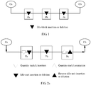
- FIG. 2a is a schematic diagram of service transport in the flexible Ethernet according to an embodiment of the present invention.
- a customer device Ca needs to send a service to a customer device Cb, and service transport may be performed between the Ca and the Cb by using a bearer network.
- the flexible Ethernet including a plurality of flexible Ethernet devices (for example, Pa, Pb, and Pc) is used as the bearer network.
- the customer device may be a device such as a router or a switch, and the flexible Ethernet device may be an Ethernet device, an OTN device, an SDH device, or the like.
- a transmit end device Pa in the flexible Ethernet may insert a quantity mark k into the original data stream, to identify a quantity of data units in the original data stream.
- the data unit includes an idle unit and a non-idle unit.
- the idle unit has a fixed data format.
- the non-idle unit is a data unit different from the idle unit, and includes a plurality of data formats. In this embodiment of the present invention, only a quantity of idle units may be marked, or a quantity of all data units may be marked.
- the transmit end device Pa may further perform same idle-unit insertion or deletion as in the prior art.
- An intermediate device Pb in the flexible Ethernet may perform same idle-unit insertion or deletion as in the prior art.
- the intermediate device may further include a plurality of devices, that is, a plurality of times of idle-unit insertion or deletion may be performed on the original data stream.
- a receive end device Pc in the flexible Ethernet extracts the quantity mark k, and performs reverse idle-unit insertion or deletion according to the quantity mark k, that is, recovers the original data stream.
- Reverse idle-unit insertion or deletion means if n idle units are inserted into the original data stream, the receive end device Pc deletes n idle units, or if n idle units are deleted from the original data stream, the receive end device Pc inserts n idle units.
- the recovered original data stream and the original data stream existing before idle-unit insertion or deletion is performed have a same quantity of data units or idle units. Therefore, the receive end device Pc can recover a clock frequency and time phase information of the original data stream according to the recovered original data stream, so that a clock frequency and time phase information of a service are transparently transported.
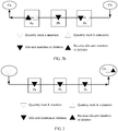
- FIG. 2b is a schematic diagram of service transport in the flexible Ethernet according to an embodiment of the present invention.
- a service is sent from a customer device Cb to a customer device Ca, and an execution procedure is opposite to that in FIG. 2a .
- a step performed by Pc in FIG. 2b is the same as a step performed by the Pa in FIG. 2a
- a step performed by Pa in FIG. 2b is the same as a step performed by the Pc in FIG. 2a .
- FIG. 3 is a schematic diagram of another type of service transport in the flexible Ethernet according to an embodiment of the present invention.
- a service is sent from a customer device Ca to a customer device Cb is used as an example for description.
- the customer device Ca may insert quantity mark k, and the customer device Cb may extract the quantity mark k, and perform reverse idle-unit insertion or deletion, to recover original data.
- Flexible Ethernet devices such as Pa, Pb, and Pc may perform same idle-unit insertion or deletion as in the prior art, without a need to make any improvement, so that the technical solutions in the present invention is well compatible with the existing flexible Ethernet.
- a data format of an original data stream may include a data format existing after encoding, or may include a data format existing when encoding is not performed.
- a format of the idle unit may include an idle code block, an idle byte unit, or the like.
- the data format existing after encoding is described by using 64b/66b encoding as an example.
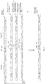
- FIG. 4 is a schematic diagram of a format of a data stream according to an embodiment of the present invention.
- a start code block S in an original data stream, a start code block S, a termination code block T, and a plurality of code blocks D are considered as a group, for example, a group 401 and a group 403 shown in the figure.
- a transmit end device may further delay the original data stream, for example, delay the original data stream by one code block in FIG. 4 .
- the transmit end device or an intermediate device may perform an insertion or deletion operation on the idle code block.
- FIG. 4 shows two cases: The idle code block 407 is deleted from the original data stream, and an idle code block 409 is inserted into the original data stream.
- a receive end device recovers the original data stream from a data stream on which idle-code-block insertion or deletion is performed.
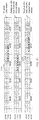
- FIG. 5 is a schematic diagram of another format of a data stream according to an embodiment of the present invention.
- a transmit end device may insert a quantity mark k into a start code block (for example, a start code block 505) in the original data stream.
- the quantity mark k In a process in which the transmit end device or an intermediate device performs idle-code-block insertion or deletion, the quantity mark k always exists in the data stream, until the quantity mark k is extracted by a receive end device for recovering the original data.
- a group 501 and a group 503 are included.
- the group 501 and the group 503 may be adjacent groups, or there may be another group between the group 501 and the group 503.
- one quantity mark k may be inserted for one group, or one quantity mark k may be inserted for a plurality of groups.
- Code blocks between a start code block of the group 501 and a start code block of the group 503 are considered as a segment of data stream (including the start code block of the group 501, and excluding the start code block of the group 503) whose length is k.
- the quantity mark k may be inserted into the start code block 505, and the quantity mark k may be used to identify a quantity of all code blocks in the segment of data stream whose length is k.
- k does not include the start code block 505 of the group 503; or certainly, may include the start code block of the group 503.
- the quantity mark k may be further used to directly identify a quantity of idle code blocks.
- the idle code block may exist between groups, or may exist in the group.
- the figure further shows the start code block 507 into which a quantity mark k0 is inserted in the group 501, and a function of the start code block 507 is similar to that of the start code block 505 carrying the quantity mark k. Details are not described herein.
- a start code block S in an Ethernet (including the flexible Ethernet) data frame is a code block with a fixed bit pattern, and is not changed in a transport process
- the start code block S includes redundant information, and can be used to carry information such as a quantity mark k.
- a preamble element includes 8-byte transmit (character) data (Transmit (character) Data, TXD)/received (character) data (Received (character) Data, RXD), and is indicated by using 8-bit transmit (character) control (signals) (Transmit (character) Control (signals), TXC)/received (character) control (signals) (Received (character) Control (signals), RXC).
- ⁇ TXC,TXD> of the preamble element is as follows: ⁇ 1,0xFB> ⁇ 0,0x55> ⁇ 0,0x55> ⁇ 0,0x55> ⁇ 0,0x55> ⁇ 0,0x55> ⁇ 0,0x55> ⁇ 0,0x55> ⁇ 0,0xD5>, where 0xFB is a start-of-frame control character "/S/", and 0xD5 is a start-of-frame delimiter (Start of Frame Delimiter, SFD).
- a data format of the encoded preamble element is referred to as a start code block, and a boundary of the 8-byte preamble element is aligned with a boundary of a 64b/66b code block, for example, "/S/" is aligned with a boundary of the start code block.
- FIG. 6 is a 64b/66b encoding format of a start code block according to an embodiment of the present invention, where the start code block includes a synchronization header "10" and a control code block type "0x78".
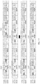
- FIG. 7 is a schematic diagram of formats of six code blocks according to an embodiment of the present invention.
- a code block 701 "0x55" of D1 is changed to "0x00", and "0xD5" of D7 is changed to "0xFF".
- D1 is changed to "0xA”.
- D7 is changed to "0xAA”.
- D7 is changed to "0xA”.
- FIG. 8 is a schematic diagram of formats of three code blocks according to an embodiment of the present invention. Code block formats of code blocks 801 and 803 are identified by using a preset pattern "0x4B+0xA”. For a code block 805, a control code block type "0x78" is changed to "0xFF”. A specific implementation is not limited to the code block formats shown in FIG. 7 and FIG. 8 , provided that a start code block carrying k can be identified.
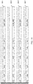
- FIG. 9 is a schematic diagram of a format of a data stream according to an embodiment of the present invention. As shown in FIG. 9 , a data stream whose length is k is divided into two segments whose lengths are k1 and k2. A quantity mark k1 may be inserted into the first code block 901 (an idle code block) following the segment k1, and is used to identify a quantity of all code blocks or a quantity of idle code blocks in the segment k1.
- a quantity mark k2 is inserted into the first code block 903 (a start code block) following the segment k2, and is used to identify a quantity of all code blocks or a quantity of idle code blocks in the segment k2.
- the idle code block and the start code block may be changed to code blocks identified by using a preset pattern.
- the idle code block 901 carrying k1 and the start code block 903 carrying k2 may be identified by using different preset patterns, so that a receive end device rapidly recovers an original code block.
- the start code block and a termination code block usually appear in pairs, to meet a pairing relationship between a character "/S/" in the start code block and a character "/T/" in the termination code block.
- the idle code block into which the quantity mark k1 is inserted may be considered as a start code block of a group.
- any idle code block following the code block carrying k1 may be set as a termination code block.
- the figure further shows a start code block 905 into which a quantity mark k0 is inserted, and a function of the start code block 905 is similar to that of the start code block 901 carrying k1 and that of the start code block 903 carrying k2. Details are not described herein.
- FIG. 10 is a schematic diagram of a format of a code block according to an embodiment of the present invention.
- a cyclic redundancy check (Cyclic Redundancy Check, CRC) check bit is set for the quantity mark k, for example, CRC8, so that a receive end device performs verification on transport reliability.
- CRC Cyclic Redundancy Check
- a quantity mark may be inserted into all start code blocks or some start code blocks in an original data stream. Inserting the quantity mark into the start code block or an idle code block is actually replacing the start code block or the idle code block with a code block carrying the quantity mark.
- the start code block or the idle code block may be first changed to a code block identified by using a preset pattern, and then, the quantity mark is inserted into the code block identified by using the preset pattern.
- the quantity mark is first inserted into the start code block or the idle code block, and then, the start code block or the idle code block into which the quantity mark is inserted is changed to a code block identified by using a preset pattern.
- a code block that is identified by using a preset pattern and that carries the quantity mark is directly inserted into a location of the start code block or the idle code block. This is not limited in the present invention.
- the data format existing when encoding is not performed is described by using a data format in which insertion or deletion is performed at a granularity of four bytes.
- an idle unit may include a plurality of idle bytes. For example, idle-byte insertion or deletion may be performed at a granularity of an idle unit including four bytes or eight bytes. Because eight bytes may be corresponding to one 64b/66b code block, a processing manner of the data format existing when encoding is not performed is similar to a processing manner of the data format existing after encoding.
- FIG. 11 is a schematic diagram of a format of a data stream according to an embodiment of the present invention. As shown in FIG. 11 , an MII byte data stream ⁇ TXC/RXC, TXD/RXD> is in a one-to-one correspondence with a 64b/66b code block.
- FIG. 11 shows three cases. In a first case, in an original data stream, a start-of-frame control character "/S/" is corresponding to the fifth location in a 64b/66b code block. In a second case, four idle bytes 1101 are deleted from the original data stream, and the start-of-frame control character "/S/" is corresponding to the first location in a 64b/66b code block. In a third case, four idle bytes 1103 are inserted into the original data stream, and the start-of-frame control character "/S/" is corresponding to the first location in a 64b/66b code block.
- FIG. 12 is a schematic diagram of a format of a data stream according to an embodiment of the present invention.
- a quantity mark k is inserted into an original data stream.
- the quantity mark k may be used to identify a quantity on the basis of per byte, or may be used to identify a quantity on the basis of per four bytes, or may be used to identify a quantity on the basis of per eight bytes.
- the quantity mark k is inserted into eight-byte units 1201 and 1202 (referred to as a preamble-element byte unit) in which a start-of-frame control character "/S/" is located and that are in the original data stream.
- the quantity mark k may be used to identify a quantity of data bytes or a quantity of idle bytes in a segment of data stream prior to the preamble-element byte unit.
- the start-of-frame control character "/S/" of the eight-byte unit 1201 is corresponding to the fifth location in a 64b/66b code block
- the start-of-frame control character "/S/"of the eight-byte unit 1203 is corresponding to the first location in a 64b/66b code block.
- the eight-byte unit carrying k may be identified by using a preset byte such as "0x00" and "0xFF".
- the field k may be further checked by using a C field (CRC).
- FIG. 13 is a schematic diagram of another format of a data stream according to an embodiment of the present invention.
- a quantity mark k1 may be inserted into the first eight-byte unit 1303 (an idle byte unit) following the segment k1, and is used to identify a quantity of all data bytes or a quantity of idle bytes in the segment k1.
- a quantity mark k2 may be inserted into the first eight-byte unit 1301 (a preamble-element byte unit) following the segment k2, and is used to identify a quantity of all data bytes or a quantity of idle bytes in the segment k2.
- a start control character "/S/" may be corresponding to the first location or the fifth location in a 64b/66b code block.
- the eight-byte unit carrying k1 may be identified by using a preset byte, for example, "0xFF" and "0x00" in the eight-byte unit 1303, "0x9C” in an eight-byte unit 1305, and "0xF0" in an eight-byte unit 1307.
- the eight-byte unit 1301 carrying k2 may be identified by using a preset byte such as "0x00" and "0xFF".
- the idle byte unit carrying k1 and the preamble-element byte unit carrying k2 may be identified by using different preset bytes, so that a receive end device rapidly recovers an original eight-byte unit.
- the fields k1 and k2 may be further checked by using a C field (CRC).
- a quantity mark may be inserted into all preamble-element byte units or some preamble-element byte units in the original data stream. Inserting the quantity mark into the preamble-element byte unit or an idle byte unit is actually replacing the preamble-element byte unit or the idle byte unit with a unit carrying the quantity mark.
- a preset byte may be first inserted into the preamble-element byte unit or the idle byte unit, and then, the quantity mark is inserted into the unit identified by using the preset byte.
- the quantity mark is first inserted into the preamble-element byte unit or the idle byte unit, and then, a preset byte is inserted into the preamble-element byte unit or the idle byte unit into which the quantity mark is inserted.
- a unit carrying the quantity mark and a preset byte may be directly inserted into a location of the preamble-element byte unit or the idle byte unit. This is not limited in the present invention.
- eight-byte units carrying k, k1, and k2 may be corresponding to five code block formats shown in FIG. 14 .
- the eight-byte units 1201 and 1203 in FIG. 12 and the eight-byte unit 1301 in FIG. 13 may be corresponding to a code block 1401.
- the eight-byte unit 1303 in FIG. 13 may be corresponding to a code block 1403.
- the eight-byte unit 1305 in FIG. 13 may be corresponding to a code block 1405.
- the eight-byte unit 1307 in FIG. 13 is corresponding to a code block 1407 or a code block 1409.
- the quantity marks k, k1, and k2 may be represented by using field lengths of 8 bits, 16 bits, 24 bits, 32 bits, and the like.
- a representation range includes 0 to 255; and when the length of 16 bits is used, a representation range includes 0 to 65535.
- different bit lengths may be selected according to a length of a segment of data stream that is obtained by means of division.
- the original data stream is divided into a plurality of segments of data streams, and a data unit, such as a start unit or an idle unit, into which a quantity mark can be inserted is found from each segment of data stream.
- the data unit into which the quantity mark is inserted may be located at a location adjacent to an identified segment of data stream, or may be located at a location that is not adjacent to an identified segment of data stream.
- the data unit into which the quantity mark is inserted may be located before an identified segment of data stream, or may be located after an identified segment of data stream. This is not limited in the present invention.
- the data unit into which the quantity mark is inserted may be used to identify a start location in a segment of data stream, or may be used to identify an end location in a segment of data stream.
- any start code block may be used to identify a start location in a segment of data stream in which the start code block is located, or may be used to identify an end location in a previous segment of data stream.
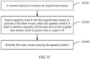
- FIG. 15 is an example flowchart of a method for sending a service according to an embodiment of the present invention. As shown in FIG. 15 , the method may be executed by a transmit end device in the flexible Ethernet, and include the following steps.
- the transmit end device obtains an original data stream.
- the original data stream may be a service data stream including an interpacket gap (Interpacket Gap, IPG), for example, an Ethernet packet service data stream.
- the IPG may be an idle unit, and has a plurality of data formats, for example, an idle packet at or above a media access control (Media Access Control, MAC) layer, an MII idle byte unit, and an idle code block having a physical layer encoding format.
- An encoding format of an idle code block is, for example, 64b/66b encoding, 8b/10b encoding, or 512b/514b encoding.
- the first data unit may be all data units in the original data stream, or may be an idle unit in the original data stream.
- the quantity mark k is used to identify a quantity of all data units in the original data stream, k may be an integer greater than 0.
- the quantity mark k is used to identify a quantity of idle units in the original data stream, k may be an integer greater than or equal to 0.
- a 40GE service and a 10GE service that are borne by the flexible Ethernet are mainly used as an example for description.
- a processing procedure of a 100GE service or an over 100GE service is similar to a processing procedure of the 40GE service, and a processing procedure of a 25GE service is similar to a processing procedure of the 10GE service.
- FIG. 16 is a schematic diagram of a data processing procedure of a 40GE physical interface according to an embodiment of the present invention. As shown in FIG.
- a physical layer structure of the 40GE physical interface includes a physical coding sublayer (Physical Coding Sub-layer, PCS) 1601, and further includes any one or more of the following sublayers: a physical medium attachment (Physical Medium Attachment, PMA) sublayer, a physical medium dependent (Physical Medium Dependent, PMD) sublayer, or forward error correction (Forward Error Correction, FEC) 1603.
- the physical layer structure of the 40GE physical interface further includes a reconciliation sublayer (Reconciliation Sub-layer, RS) (which is not shown in the figure).
- the XLGMII interface is located between the RS and the PCS.
- Sending-direction processing 1605 of the PCS may include encoding, scrambling, multichannel distribution, an alignment code block (Alignment Marker, AM) insertion, and the like.
- Receiving-direction processing 1607 of the PCS may include multichannel element synchronization, AM locking and channel alignment, bit error rate (Bit Error Rate, BER) monitoring, channel reordering and combination to obtain a serial element, AM deletion, descrambling, decoding, and the like.
- Bit Error Rate, BER bit error rate
- FIG. 16 refer to the prior art.
- the PCS needs to distribute the data stream to a plurality of channels (multichannel distribution), and insert an AM (AM insertion) into each channel.
- the PCS receives data streams from a plurality of channels, performs alignment and reordering on the data streams on the plurality of channels, to recover a serial data stream (multichannel element synchronization, AM locking and channel alignment, and channel reordering and combination to obtain a serial element), deletes the AM of each channel (AM deletion), and performs descrambling and decoding.
- step S1503 may be performed after the descrambling in the receiving-direction processing 1607 of the 40GE physical interface, or may be performed before or after the decoding.
- This embodiment of the present invention may be implemented based on the data processing procedure shown in FIG. 16 , but is not limited to the example shown in FIG. 16 .
- the data processing procedure may not include the AM deletion step. If the AM is not deleted, when the quantity mark k is inserted, the AM further needs to be used as a data unit in the original data stream for statistics collection.
- FIG. 17 is a schematic diagram of AM format conversion according to an embodiment of the present invention. As shown in FIG.
- FIG. 18 is a schematic diagram of formats of four code blocks according to an embodiment of the present invention. As shown in FIG. 18 , AM0, AM1, AM2, and AM3 are respectively replaced with code blocks 1801, 1803, 1805, and 1807. Alternatively, AM0, AM1, AM2, and AM3 may be replaced with four same code blocks, for example, any one of the foregoing four code blocks.
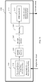
- FIG. 19 is a schematic structural diagram of a transmit end device 1900 according to an embodiment of the present invention.
- the transmit end device 1900 receives the original data stream from PMA/PMD/FEC 1901 of a 40GE physical interface.
- receives-direction processing 1903 of a PCS of the 40GE physical interface refer to the receiving-direction processing 1607 shown in FIG. 16 .
- the receiving-direction processing 1903 of the PCS may be implemented by using a physical circuit, or may be implemented by using a logic circuit, or may be implemented by using hardware, software, or a combination of hardware and software.
- Quantity mark k insertion 1905 may be implemented during the receiving-direction processing 1903 of the PCS, or may be implemented after the receiving-direction processing 1903 of the PCS.
- idle-unit insertion or deletion 1907 may be performed for rate adaption.
- idle-unit insertion or deletion for rate adaption refer to the prior art.
- the first data stream into which the quantity mark k is inserted may be sent by using a 40GE logical port 1911 formed by a flexible Ethernet physical interface (or an interface group) 1909.
- FIG. 20 is a schematic diagram of a data processing procedure of a 10GE physical interface according to an embodiment of the present invention.
- An MII of the 10GE physical interface is referred to as an XGMII
- the XGMII uses a data bit width of 32 bits
- a start-of-frame control character is aligned with a boundary of four bytes, that is, the start-of-frame control character may be located at the fifth location or the first location in a 64b/66b code block.
- a physical layer structure of the 10GE physical interface is similar to that of the 40GE physical interface, and includes a PCS 2001 and any one or more of the following sublayers: PMA, PMD, or FEC 2003.
- Sending-direction processing 2005 of the PCS may include encoding and scrambling.
- Receiving-direction processing 2007 of the PCS may include element synchronization, descrambling, and decoding.
- time division multiplexing Time Division Multiplex, TDM
- TDM Time Division Multiplex
- 64b/66b code block based on a 100GE physical interface
- code block type conversion needs to be performed on the 10GE service. That is, in a receiving direction 2007 of the PCS, decoding (for example, 64b/66b decoding) is first performed, and then, idle-byte insertion or deletion is performed based on a decoded MII byte data stream.
- a data stream may be moved forwards or backwards by 4 bytes by means of idle-byte insertion or deletion, so that the start-of-frame control character is aligned with a boundary of the 64b/66b code block.
- step S1503 may be performed after or before the decoding in the receiving direction 2007 of the 10GE physical interface.
- this embodiment of the present invention may be implemented based on the data processing procedure shown in FIG. 20 , but is not limited to the example shown in FIG. 20 .
- the data processing procedure may not include the decoding step, and in this case, S1503 may be performed after the descrambling.
- FIG. 21 is a schematic structural diagram of a transmit end device 2100 according to an embodiment of the present invention.
- the transmit end device 2100 receives the original data stream from PMA/PMD/FEC 2101 of a 10GE physical interface.
- For receiving-direction processing 2103 of a PCS of the 10GE physical interface refer to the receiving-direction processing 2007 shown in FIG. 20 .
- the receiving-direction processing 2103 of the PCS may be implemented by using a physical circuit, or may be implemented by using a logic circuit, or may be implemented by using hardware, software, or a combination of hardware and software.
- Quantity mark k insertion 2105 may be implemented during the receiving-direction processing 2103 of the PCS, or may be implemented after the receiving-direction processing 2103 of the PCS.
- idle-unit insertion or deletion 2107 may be performed for rate adaption.
- encoding 2109 is performed on the first data stream into which the quantity mark k is inserted, and the first data stream is sent by using a 10GE logical port 2113 formed by a flexible Ethernet physical interface (or an interface group) 2111.
- the quantity mark k insertion 2105 and idle-unit insertion or deletion 2107 may be performed before the encoding 2109, or may be performed after the encoding 2109. If there is no decoding in the receiving-direction processing of the PCS, no encoding needs to be performed herein.
- FIG. 22 is a flowchart of a quantity mark insertion method according to an embodiment of the present invention.
- a counter is set, and when a data unit is received from an original data stream, a value of the counter is increased by 1.
- a data format of the data unit may include a code block, a byte, or the like.
- the data format of the data unit is a code block
- a data unit in the original data stream may include a start code block S, a termination code block T, a code block D, and an idle code block (Idle), and may further include an AM code block, or the like.
- S2202 if the current data unit is a start unit, for example, a start code block S, S2203 is performed, to insert a current value k (a quantity mark k) of the counter into the current data unit, that is, replace the current data unit with a data unit carrying k, and reset the counter to 0.
- a current value k a quantity mark k
- S2202 if the current data unit is not a start unit, whether a quantity mark k can be inserted into the current data unit needs to be determined according to the value of the counter.
- S2204 if the current value k of the counter is greater than or equal to a preset threshold, S2205 is performed, to determine whether the quantity mark k can be inserted into the current data unit. For example, if the current data unit is an idle unit, the quantity mark k may be inserted into the current idle unit. If the current data unit is not an idle unit, unit conversion may be performed on the current data unit, and then, the quantity mark k is inserted.
- the current data unit carries a command word such as a local fault (Local Fault, LF) or a remote fault (Remote Fault, RF), the LF, the RF, or the like is carried by another idle code block, and the quantity mark k is inserted into a location of the current data unit.
- the quantity mark k cannot be inserted into the current data unit, S2206 is performed, to end the procedure, receive a next data unit in the original data stream, and determine whether the quantity mark k can be inserted into the next data unit.
- S2204 if the current value k of the counter is less than a threshold, S2206 is performed, to end the procedure to continue to receive a next data unit of the original data stream.
- threshold setting of the value of the counter refer to a bit length carrying the quantity mark k. A higher bit length indicates that a larger threshold may be set.
- the quantity mark k may be inserted after the current data unit is replaced with a unit having a preset format. Alternatively, the quantity mark k may be inserted before the current data unit is replaced with a unit having a preset format.
- the quantity mark k may be directly inserted into a redundant field or an idle field in the current data unit. For how to insert the quantity mark k into a data unit, refer to the foregoing principle of marking the quantity of idle units. Details are not described herein.
- the transmit end device adds the quantity mark k into the original data stream, and the quantity mark k is used to identify the quantity of data units or idle units in the original data stream.
- a receive end device can recover the original data stream according to the quantity mark k, to recover a clock frequency and time phase information of the original data stream, so that a clock frequency and time phase information of a service are transparently transported.
- FIG. 23 is an example flowchart of a method for receiving a service according to an embodiment of the present invention. As shown in FIG. 23 , the method may be executed by a receive end device in the flexible Ethernet, and include the following steps.
- the receive end device receives a first data stream.
- a data format of the first data stream may be the same as that of an original data stream, or may be different from that of an original data stream.
- both the original data stream and the first data stream are data streams on which encoding is performed.
- the original data stream is a data stream on which encoding is not performed
- the first data stream is a data stream on which encoding is performed.
- the first data unit may be all data units in the original data stream, or may be an idle unit in the original data stream.
- the quantity mark k is used to identify a quantity of all data units in the original data stream, k may be an integer greater than 0.
- the quantity mark k is used to identify a quantity of idle units in the original data stream, k may be an integer greater than or equal to 0.
- a 40GE service and a 10GE service that are borne by the flexible Ethernet are mainly used as an example for description.
- a processing procedure of a 100GE service or an over 100GE service is similar to a processing procedure of the 40GE service, and a processing procedure of a 25GE service is similar to a processing procedure of the 10GE service.
- This embodiment of the present invention may be implemented based on the data processing procedure shown in FIG. 16 , but is not limited to the example shown in FIG. 16 .
- the data processing procedure may not include the AM insertion step. If the first data stream may be received from a 40GE logical interface, steps S2303 and S2305 may be performed before the scrambling in the sending-direction processing 1605 of the 40GE physical interface, or may be performed before or after the encoding.
- FIG. 24 is a schematic structural diagram of a receive end device 2400 according to an embodiment of the present invention.
- the receive end device 2400 receives the first data stream by using a 40GE logical port 2403 formed by a flexible Ethernet physical interface (interface group) 2401, recovers the original data stream from the first data stream, and then, may send the recovered original data stream to a customer device by using PMA/PMD/FEC 2409 of a 40GE physical interface.
- For sending-direction processing 2411 of a PCS of the 40GE physical interface refer to the sending-direction processing 1605 shown in FIG. 16 .
- the sending-direction processing 2411 of the PCS may be implemented by using a physical circuit, or may be implemented by using a logic circuit, or may be implemented by using hardware, software, or a combination of hardware and software.
- Quantity mark k extraction 2405 and original data recovery 2407 may be implemented during the sending-direction processing 2411 of the PCS, or may be implemented at the 40GE logical port 2403, or may be independently implemented.
- This embodiment of the present invention may be implemented based on the data processing procedure shown in FIG. 20 , but is not limited to the example shown in FIG. 20 .
- the data processing procedure may not include the encoding step. If the original data stream may be received from a 10GE logical port, steps S2303 and S2305 may be performed after or before the encoding in the sending-direction processing 2005 of the 10GE physical interface.
- FIG. 25 is a schematic structural diagram of a receive end device 2500 according to an embodiment of the present invention.
- the receive end device 2500 receives the first data stream by using a 10GE logical port 2503 formed by a flexible Ethernet physical interface (interface group) 2501, recovers the original data stream from the first data stream, and then, may send the recovered original data stream to a customer device by using PMA/PMD/FEC 2511 of a 10GE physical interface.
- For sending-direction processing 2513 of a PCS of the 10GE physical interface refer to the sending-direction processing 2005 shown in FIG. 20 .
- the sending-direction processing 2513 of the PCS may be implemented by using a physical circuit, or may be implemented by using a logic circuit, or may be implemented by using hardware, software, or a combination of hardware and software.
- Quantity mark k extraction 2507 and original data recovery 2509 may be implemented during the sending-direction processing 2513 of the PCS, or may be implemented at the 10GE logical port 2503, or may be independently implemented.
- the quantity mark k extraction 2507 and the original data recovery 2509 may be performed after decoding 2505, or may be performed before decoding 2505.
- FIG. 26 is a flowchart of a quantity mark extraction method according to an embodiment of the present invention.
- a counter is set, and when a data unit is received from a first data stream, a value of the counter is increased by 1.
- a data format of the data unit may include a code block, a byte, or the like.
- the data format of the data unit is a code block
- a data unit in the first data stream may include a start code block S, a termination code block T, a code block D, and an idle code block (Idle), and the like.
- S2603 if the current data unit carries a quantity mark k, S2603 is performed, to determine whether the quantity mark k is equal to a current value kn of the counter.
- S2604 if kn ⁇ k, (k-kn) idle units are inserted before the current data unit.
- S2605 if kn>k, (kn-k) idle units are deleted before the current data unit.
- the start unit is recovered from the current data unit.
- the current data unit from which the original data unit is recovered is sent to a cache queue.
- the procedure ends, to continue to receive a next data unit of the first data stream.
- the current data unit does not carry a quantity mark k, the current data unit is sent to a cache queue.
- the procedure ends, to continue to receive a next data unit of the first data stream.
- the recovered data stream and an original data stream obtained by a transmit end device have a same quantity of data units, or have a same quantity of idle units, so that the original data stream is recovered.
- FIG. 27 is a schematic structural diagram of a clock frequency recovery system according to an embodiment of the present invention.
- a transmit end device 2701 and an intermediate device 2703 may perform idle-unit insertion or deletion, to implement rate adaption. Therefore, a clock frequency is changed in a transport process.
- the transmit end device 2701 receives an original data stream whose clock frequency is f 0 , and sends a first data stream whose clock frequency is f 1 .
- the first data stream may pass at least one intermediate device 2703, and the intermediate device 2703 may change the clock frequency of the first data stream, for example, from f 1 to f 2 .
- a receive end device 2705 recovers a clock frequency f 0' of the original data stream from the clock frequency f 2 of the first data stream.
- the recovered clock frequency f 0' may be slightly different from the original clock frequency f 0 . However, when a difference between the two frequencies falls within an allowable range, it may be considered that the original clock frequency is recovered.
- the transmit end device 2701 inserts a quantity mark k into a data stream, and the receive end device 2705 may extract the quantity mark k from a received data stream.
- specific cache space needs to be set for the transmit end device 2701, the intermediate device 2703, and the receive end device 2705.
- a depth of a cache queue may be adjusted in real time according to a difference between the quantity mark k and a value kn of a counter. For example, when the difference between k and kn is relatively large, the depth of the queue is relatively large. Referring to the method procedure in FIG.
- a data unit in the first data stream is sent to the cache queue, and the original data stream is recovered.
- the receive end device 2705 may monitor an average watermark of the queue, and when the average watermark gradually increases, a clock frequency of the original data stream that is output from the queue gradually increases. When the average watermark gradually decreases, a clock frequency of the original data stream that is output from the queue gradually decreases. Smooth filtering may be performed, by using a clock processing circuit, on the clock frequency of the original data stream that is output from the queue, to keep the average watermark of the queue stable and unchanged, so that the original clock frequency f 0' is stably generated.
- the receive end device extracts the quantity mark k from the first data stream, and the quantity mark k is used to identify the quantity of data units or idle units in the original data stream.
- the receive end device can recover the original data stream according to the quantity mark k, to recover a clock frequency and time phase information of the original data stream, so that a clock frequency and time phase information of a service are transparently transported.
- FIG. 15 and FIG. 23 may be further implemented on a customer device.
- a 100GE service is used as an example for description, and a principle of a 100GE physical interface is similar to a principle of a 40GE physical interface.
- FIG. 28 is a schematic structural diagram of a customer device according to an embodiment of the present invention. As shown in FIG. 28 , a transmit end method may be executed after encoding in a sending direction 2801 of a 100GE physical interface and before scrambling, and a receive end method may be executed after descrambling in a receiving direction 2803 of the 100GE physical interface and before decoding.
- FIG. 29 is a schematic structural diagram of another customer device according to an embodiment of the present invention. As shown in FIG. 29 , a transmit end method may be executed before encoding in a sending direction 2901 of a 100GE physical interface, and a receive end method may be executed after decoding in a receiving direction 2903 of the 100GE physical interface.
- FIG. 30 is a schematic structural diagram of an apparatus 3000 for sending a service according to an embodiment of the present invention.
- the apparatus may be a flexible Ethernet device, an Ethernet device, an OTN device, an SDH device, or the like.
- the apparatus 3000 may include: an obtaining module 3001, an insertion module 3003, and a sending module 3005.
- the function modules are obtained by means of logical division, and a division manner is not limited.
- each module may be an independent circuit module, or may be integrated into a circuit module.
- Each module may be implemented by using an integrated circuit such as a chip.
- the apparatus 3000 for sending a service in this embodiment of the present invention may perform the method steps in the embodiment shown in FIG. 15 .
- the obtaining module 3001 is configured to obtain an original data stream.
- the insertion module 3003 is configured to insert a quantity mark k into the original data stream, to generate a first data stream.
- the quantity mark k is used to identify a quantity of first data units in the original data stream, and k is greater than or equal to 0.
- the sending module 3005 is configured to send the first data stream.
- the insertion module 3003 is configured to: obtain a first segment of data stream from the original data stream, and determine a quantity of first data units in the first segment of data stream; and insert the quantity mark k at a first location in the first segment of data stream.
- a value of the quantity mark k is equal to the quantity of first data units in the first segment of data stream, and the first location is a location of a data unit that can be used to carry the quantity mark k.
- the first data unit includes all data units in the first segment of data stream, and k is an integer greater than 0.
- the first data unit is an idle unit in the first segment of data stream, and k is an integer greater than or equal to 0.
- the insertion module 3003 is configured to: identify a start unit in the original data stream, and determine a location of the start unit as the first location.
- the insertion module 3003 is configured to: set a threshold of the quantity mark k; when a length of the first segment of data stream is greater than or equal to the threshold, identify a first idle unit in the first segment of data stream; and determine a location of the first idle unit as the first location.
- Encoding processing has been performed on the first data unit, or encoding processing has not been performed on the first data unit.
- the apparatus 3000 further includes: an insertion or deletion module, configured to increase and/or decrease a quantity of idle units in the first data stream.
- the apparatus for sending a service adds the quantity mark k into the original data stream, and the quantity mark k is used to identify a quantity of data units or idle units in the original data stream.
- an apparatus for receiving a service can recover the original data stream according to the quantity mark k, to recover a clock frequency and time phase information of the original data stream, so that a clock frequency and time phase information of a service are transparently transported.
- FIG. 31 is a schematic structural diagram of an apparatus 3100 for receiving a service according to an embodiment of the present invention.
- the apparatus may be a flexible Ethernet device, an Ethernet device, an OTN device, an SDH device, or the like.
- the apparatus may include: a receiving module 3101, an extraction module 3103, and a recovery module 3105.
- the function modules are obtained by means of logical division, and a division manner is not limited.
- each module may be an independent circuit module, or may be integrated into a circuit module.
- Each module may be implemented by using an integrated circuit such as a chip.
- the apparatus 3100 for sending a service in this embodiment of the present invention may perform the method steps in the embodiment shown in FIG. 23 .
- the receiving module 3101 is configured to receive a first data stream.
- the extraction module 3103 is configured to: extract a quantity mark k from the first data stream, and determine a quantity of first data units in the first data stream, where k is greater than or equal to 0.
- the recovery module 3105 is configured to recover the original data stream from the first data stream. A quantity of first data units in the original data stream is equal to k.
- the extraction module 3103 is configured to: obtain a first segment of data stream from the first data stream, determine a first location in the first segment of data stream, and extract the quantity mark k from the first location.
- the first location is a location of a data unit that can be used to carry the quantity mark k.
- the first data unit includes all data units in the first segment of data stream, and k is an integer greater than 0.
- the first data unit is an idle unit in the first segment of data stream, and k is an integer greater than or equal to 0.
- the recovery module 3105 configured to: determine a quantity m of first data units in the first segment of data stream, and adjust the quantity m of first data units in the first segment of data stream according to a difference between m and k, so that m is equal to k.
- the recovery module 3105 is configured to: when m is greater than k, delete (m-k) idle units from the first segment of data stream; or when m is less than k, insert (k-m) idle units into the first segment of data stream.
- the apparatus 3100 further includes a clock module, configured to recover a clock frequency of the original data stream.
- the apparatus for receiving a service extracts the quantity mark k from the first data stream, and the quantity mark k is used to identify a quantity of data units or idle units in the original data stream.
- the apparatus for receiving a service can recover the original data stream according to the quantity mark k, to recover a clock frequency and time phase information of the original data stream, so that a clock frequency and time phase information of a service are transparently transported.
- FIG. 32 is a schematic structural diagram of a network system according to an embodiment of the present invention.
- the network system may be the flexible Ethernet, the Ethernet, an OTN network, an SDH network, or the like.
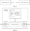
- the network system may include at least two network devices, for example, a network device 3201 and a network device 3203.
- Each network device may be a sending network device or a receiving network device, and may have the structure shown in FIG. 30 and/or FIG. 31 .
- FIG. 33 is a schematic structural diagram of a network device according to an embodiment of the present invention.
- the network device may be the flexible Ethernet device, an Ethernet device, an OTN device, an SDH device, or the like.
- the network device 3300 may include: a processor 3301, a memory 3302, at least one network interface (for example, a network interface 3303 and network interface 3304), and a processing chip 3305.
- the processor 3301 may use a general-purpose central processing unit (Central Processing Unit, CPU), a microprocessor, a network processor (Network Processing Unit, NPU), an application-specific integrated circuit (Application Specific Integrated Circuit, ASIC), or at least one integrated circuit to execute a related program, to implement the technical solutions provided in the embodiments of the present invention.
- CPU Central Processing Unit
- NPU Network Processing Unit
- ASIC Application Specific Integrated Circuit
- the memory 3302 may be a read-only memory (Read Only Memory, ROM), a static storage device, a dynamic storage device, or a random access memory (Random Access Memory, RAM).
- the memory 3302 may store an operating system and another application program.
- program code used to implement the technical solutions provided in the embodiments of the present invention is stored in the memory 3302, and is executed by the processor 3301.
- the network interface 3303 and the network interface 3304 each use a transceiver apparatus which includes but is not limited to a transceiver, to implement communication between the network device 3300 and another device or communications network.
- the network interface 3303 and the network interface 3304 each may have a sending function or a receiving function, or may have both a sending function and a receiving function.
- the network interface 3303 and the network interface 3304 each may be a logical port (for example, a logical port formed by several timeslots), or may be a physical interface (for example, a 100G flexible Ethernet physical interface).
- the processing chip 3305 may be implemented by using an ASIC, a field-programmable gate array (Field-Programmable Gate Array, FPGA), or the like.
- the processing chip 3305 may be a dedicated chip for implementing the technical solutions in the present invention, or may be a general-purpose chip having functions of the technical solutions in the present invention.
- the network device 3300 obtains an original data stream by using the network interface 3303 or the network interface 3304.
- the network device 3300 executes, by using the processor 3301, the code stored in the memory 3302, or the processing chip 3305 executes code stored in the processing chip 3305, to perform the following steps: inserting a quantity mark k into the original data stream, to generate a first data stream, where the quantity mark k is used to identify a quantity of first data units in the first original data stream, and k is greater than or equal to 0; and sending the first data stream by using the network interface 3304 or the network interface 3303.
- the network device 3300 receives a first data stream by using the network interface 3303 or the network interface 3304.
- the network device 3300 executes, by using the processor 3301, the code stored in the memory 3302, or the processing chip 3305 executes code stored in the processing chip 3305, to perform the following steps: extracting a quantity mark k from the first data stream, and determining a quantity of first data units in the first data stream, where k is greater than or equal to 0; and recovering the original data stream from the first data stream, where a quantity of first data units in the original data stream is equal to k.
- the technical solutions in any embodiment of the present invention may be implemented by using the network device 3300 shown in FIG. 33 .
- the apparatus 3000 in FIG. 30 and the apparatus 3100 in FIG. 31 may be implemented by using the structure and the solutions of the network device 3300.
- the network device 3300 shown in FIG. 33 only the processor 3301, the memory 3302, the network interface 3303 and the network interface 3304, and the processing chip 3305 are shown, in a specific implementation process, a person skilled in the art should understand that the network device 3300 further includes another component required for implementing normal running.
- the network device 3300 may further include a hardware component for implementing another additional function.
- the network device 3300 may include a power supply, a fan, a clock unit, a control unit, or the like.
- the network device 3300 may also include only a component required for implementing the embodiments of the present invention, and does not need to include all components shown in FIG. 33 .
- a transmit end network device adds the quantity mark k into the original data stream, and the quantity mark k is used to identify a quantity of data units or idle units in the original data stream.
- a receive end network device can determine, according to the quantity mark k, the quantity of data units or idle units in the original data stream, to recover the original data stream, and recover a clock frequency and time phase information of the original data stream, so that a clock frequency and time phase information of a service are transparently transported.
Landscapes
- Engineering & Computer Science (AREA)
- Computer Networks & Wireless Communication (AREA)
- Signal Processing (AREA)
- Data Exchanges In Wide-Area Networks (AREA)
- Two-Way Televisions, Distribution Of Moving Picture Or The Like (AREA)
- Synchronisation In Digital Transmission Systems (AREA)
- Time-Division Multiplex Systems (AREA)
Applications Claiming Priority (2)
| Application Number | Priority Date | Filing Date | Title |
|---|---|---|---|
| CN201610723799.6A CN107786320B (zh) | 2016-08-25 | 2016-08-25 | 一种发送和接收业务的方法、装置和网络系统 |
| PCT/CN2017/098490 WO2018036485A1 (zh) | 2016-08-25 | 2017-08-22 | 一种发送和接收业务的方法、装置和网络系统 |
Publications (3)
| Publication Number | Publication Date |
|---|---|
| EP3496344A1 true EP3496344A1 (de) | 2019-06-12 |
| EP3496344A4 EP3496344A4 (de) | 2019-07-03 |
| EP3496344B1 EP3496344B1 (de) | 2023-06-21 |
Family
ID=61246435
Family Applications (1)
| Application Number | Title | Priority Date | Filing Date |
|---|---|---|---|
| EP17842907.2A Active EP3496344B1 (de) | 2016-08-25 | 2017-08-22 | Verfahren und vorrichtungen zum senden und empfangen von diensten und netzwerksystem |
Country Status (6)
| Country | Link |
|---|---|
| US (2) | US10715306B2 (de) |
| EP (1) | EP3496344B1 (de) |
| JP (1) | JP6867473B2 (de) |
| KR (1) | KR102209296B1 (de) |
| CN (1) | CN107786320B (de) |
| WO (1) | WO2018036485A1 (de) |
Cited By (4)
| Publication number | Priority date | Publication date | Assignee | Title |
|---|---|---|---|---|
| WO2022031896A1 (en) * | 2020-08-07 | 2022-02-10 | Hyannis Port Research, Inc. | Systems and methods for clock synchronization using special physical layer clock sync symbols |
| EP3876443A4 (de) * | 2018-11-02 | 2022-09-07 | ZTE Corporation | Verfahren und vorrichtung zum senden von diensten, verfahren und vorrichtung zum empfangen von diensten sowie system und speichermedium |
| EP4068661A4 (de) * | 2019-12-18 | 2023-01-11 | Huawei Technologies Co., Ltd. | Datenübertragungsverfahren und -vorrichtung |
| EP4391438A4 (de) * | 2021-09-13 | 2024-12-04 | Huawei Technologies Co., Ltd. | Kommunikationsverfahren, zugehörige vorrichtung und speichermedium |
Families Citing this family (10)
| Publication number | Priority date | Publication date | Assignee | Title |
|---|---|---|---|---|
| WO2019050926A1 (en) * | 2017-09-06 | 2019-03-14 | Nantcell, Inc. | METHODS AND POLY THERAPIES BASED ON ALDOXORUBICIN |
| CN109962762B (zh) * | 2017-12-25 | 2020-06-16 | 华为技术有限公司 | 一种数据传输方法、发送装置及接收装置 |
| CN110417542B (zh) * | 2018-04-26 | 2022-03-18 | 中兴通讯股份有限公司 | 一种传输客户业务的方法、装置和系统 |
| CN110830153B (zh) | 2018-08-07 | 2021-04-09 | 华为技术有限公司 | 接收码块流的方法、发送码块流的方法和通信装置 |
| CN112398756B (zh) * | 2019-08-13 | 2024-05-17 | 华为技术有限公司 | 用于传输业务数据的方法和装置 |
| CN112751645A (zh) * | 2019-10-29 | 2021-05-04 | 华为技术有限公司 | 一种通信方法、设备及存储介质 |
| CN113972989B (zh) * | 2020-07-06 | 2023-09-15 | 宇龙计算机通信科技(深圳)有限公司 | 数据校验方法及存储介质、电子设备 |
| CN113285579B (zh) * | 2021-05-28 | 2022-05-03 | 普源精电科技股份有限公司 | 多通道信号的同步方法、电源模块、电子设备及电源设备 |
| CN117294579A (zh) * | 2022-06-17 | 2023-12-26 | 华为技术有限公司 | 数据处理装置、主备切换方法以及系统 |
| WO2024067959A1 (en) * | 2022-09-28 | 2024-04-04 | Telefonaktiebolaget Lm Ericsson (Publ) | Methods and apparatus of communicating in a physical coding sublayer |
Family Cites Families (22)
| Publication number | Priority date | Publication date | Assignee | Title |
|---|---|---|---|---|
| US5384774A (en) * | 1993-01-11 | 1995-01-24 | At&T Corp. | Asynchronous transfer mode (ATM) payload synchronizer |
| JP3169335B2 (ja) * | 1996-03-06 | 2001-05-21 | 三菱電機株式会社 | 回線接続装置 |
| JPH11298488A (ja) * | 1998-04-13 | 1999-10-29 | Oki Electric Ind Co Ltd | パケット伝送方法及び装置、並びにネットワーク |
| DE10241718B4 (de) * | 2002-09-09 | 2011-03-31 | Texas Instruments Deutschland Gmbh | Vorrichtung und Verfahren zum Aufbereiten von Datenzellen |
| JP3875948B2 (ja) * | 2002-11-29 | 2007-01-31 | 日本電信電話株式会社 | フレーム信号処理方法及び中継装置 |
| JP4110964B2 (ja) * | 2002-12-25 | 2008-07-02 | 日本電気株式会社 | 伝送システムおよびデータ転送方法 |
| US7512150B2 (en) * | 2003-03-24 | 2009-03-31 | Applied Micro Circuits Corporation | 10 GbE LAN signal mapping to OTU2 signal |
| KR100643287B1 (ko) * | 2004-11-19 | 2006-11-10 | 삼성전자주식회사 | 플래시 메모리의 데이터 처리 장치 및 방법 |
| CN100486252C (zh) * | 2005-10-18 | 2009-05-06 | 中兴通讯股份有限公司 | 支持多载波高速下行分组接入的数据并行调度系统及方法 |
| US7809017B2 (en) * | 2006-09-21 | 2010-10-05 | Nortel Networks Limited | Multi-rate transparent MUX for optical communications networks |
| CN101123584B (zh) * | 2007-05-21 | 2010-11-10 | 华为技术有限公司 | 一种测量ip链路丢包情况的方法及设备 |
| JP4973729B2 (ja) | 2007-06-07 | 2012-07-11 | 富士通株式会社 | 動画像類似判定装置、および動画像類似判定方法 |
| CN101335751A (zh) * | 2007-06-29 | 2008-12-31 | 华为技术有限公司 | 将以太网编码块映射到光传输网络传输的方法及装置 |
| CN101335750B (zh) * | 2007-06-29 | 2012-08-08 | 华为技术有限公司 | 将以太网编码块映射到光传输网络传输的方法及装置 |
| JP4885820B2 (ja) * | 2007-10-24 | 2012-02-29 | 日本電信電話株式会社 | ディジタル伝送装置およびディジタル伝送プログラム |
| EP2073459A1 (de) * | 2007-12-17 | 2009-06-24 | Alcatel-Lucent Deutschland AG | Übertragung über ein Netz mit Burst- oder Frame-Schaltung bei Erhaltung der Zeitplanung für die übertragenen Kundenpakete |
| WO2009115481A1 (en) * | 2008-03-20 | 2009-09-24 | Nokia Siemens Networks Oy | Method and device for data processing via a gigabit ethernet optical transmission link |
| JP4878648B2 (ja) * | 2010-03-12 | 2012-02-15 | 日本電信電話株式会社 | クライアント信号収容多重装置及び方法 |
| CN102761489B (zh) * | 2012-07-17 | 2015-07-22 | 中国科学技术大学苏州研究院 | 基于流水线模式的数据包零拷贝的核间通信方法 |
| CN107682217B (zh) * | 2014-01-14 | 2021-07-27 | 广东经纬天地科技有限公司 | 以太网信号调度方法、装置和系统 |
| CN103916217B (zh) * | 2014-03-25 | 2017-06-13 | 烽火通信科技股份有限公司 | Xlgmii接口多通道降频dic机制的实现方法及装置 |
| CN105871502B (zh) * | 2015-01-22 | 2020-01-03 | 华为技术有限公司 | 一种利用以太网信道传输业务信号的方法及通信设备 |
-
2016
- 2016-08-25 CN CN201610723799.6A patent/CN107786320B/zh active Active
-
2017
- 2017-08-22 JP JP2019511366A patent/JP6867473B2/ja active Active
- 2017-08-22 KR KR1020197008011A patent/KR102209296B1/ko active Active
- 2017-08-22 EP EP17842907.2A patent/EP3496344B1/de active Active
- 2017-08-22 WO PCT/CN2017/098490 patent/WO2018036485A1/zh not_active Ceased
-
2019
- 2019-02-22 US US16/282,690 patent/US10715306B2/en active Active
-
2020
- 2020-07-07 US US16/922,568 patent/US11038664B2/en active Active
Cited By (6)
| Publication number | Priority date | Publication date | Assignee | Title |
|---|---|---|---|---|
| EP3876443A4 (de) * | 2018-11-02 | 2022-09-07 | ZTE Corporation | Verfahren und vorrichtung zum senden von diensten, verfahren und vorrichtung zum empfangen von diensten sowie system und speichermedium |
| US12040981B2 (en) | 2018-11-02 | 2024-07-16 | Xi'an Zhongxing New Software Co., Ltd. | Service receiving methods, device, system and storage medium |
| EP4068661A4 (de) * | 2019-12-18 | 2023-01-11 | Huawei Technologies Co., Ltd. | Datenübertragungsverfahren und -vorrichtung |
| WO2022031896A1 (en) * | 2020-08-07 | 2022-02-10 | Hyannis Port Research, Inc. | Systems and methods for clock synchronization using special physical layer clock sync symbols |
| US11483087B2 (en) | 2020-08-07 | 2022-10-25 | Hyannis Port Research, Inc. | Systems and methods for clock synchronization using special physical layer clock sync symbols |
| EP4391438A4 (de) * | 2021-09-13 | 2024-12-04 | Huawei Technologies Co., Ltd. | Kommunikationsverfahren, zugehörige vorrichtung und speichermedium |
Also Published As
| Publication number | Publication date |
|---|---|
| EP3496344A4 (de) | 2019-07-03 |
| US20200336283A1 (en) | 2020-10-22 |
| WO2018036485A1 (zh) | 2018-03-01 |
| KR20190039300A (ko) | 2019-04-10 |
| JP2019531642A (ja) | 2019-10-31 |
| CN107786320B (zh) | 2021-06-22 |
| US11038664B2 (en) | 2021-06-15 |
| CN107786320A (zh) | 2018-03-09 |
| JP6867473B2 (ja) | 2021-04-28 |
| EP3496344B1 (de) | 2023-06-21 |
| US20190190690A1 (en) | 2019-06-20 |
| US10715306B2 (en) | 2020-07-14 |
| KR102209296B1 (ko) | 2021-01-29 |
Similar Documents
| Publication | Publication Date | Title |
|---|---|---|
| EP3496344B1 (de) | Verfahren und vorrichtungen zum senden und empfangen von diensten und netzwerksystem | |
| US11165698B2 (en) | Method for transmitting service signal by using ethernet channel and communications device | |
| US9954644B2 (en) | Ethernet data processing method, physical layer chip and Ethernet equipment | |
| US11223438B2 (en) | Service transmission method, network device, and network system | |
| US11552721B2 (en) | Clock synchronization method and apparatus | |
| US11140079B2 (en) | Service sending method and apparatus, service receiving method and apparatus, and network system | |
| CN110768742B (zh) | Oam消息的传输方法、发送设备、接收设备及可读存储介质 | |
| US20070116055A1 (en) | Transmission apparatus | |
| US20110283020A1 (en) | Method and system for physical layer aggregation | |
| US20240297849A1 (en) | Service processing method and service processing device | |
| US8160057B2 (en) | Multi-channel optical transport network training signal | |
| WO2024087975A1 (zh) | 一种通信方法及装置 |
Legal Events
| Date | Code | Title | Description |
|---|---|---|---|
| STAA | Information on the status of an ep patent application or granted ep patent |
Free format text: STATUS: THE INTERNATIONAL PUBLICATION HAS BEEN MADE |
|
| PUAI | Public reference made under article 153(3) epc to a published international application that has entered the european phase |
Free format text: ORIGINAL CODE: 0009012 |
|
| STAA | Information on the status of an ep patent application or granted ep patent |
Free format text: STATUS: REQUEST FOR EXAMINATION WAS MADE |
|
| 17P | Request for examination filed |
Effective date: 20190308 |
|
| AK | Designated contracting states |
Kind code of ref document: A1 Designated state(s): AL AT BE BG CH CY CZ DE DK EE ES FI FR GB GR HR HU IE IS IT LI LT LU LV MC MK MT NL NO PL PT RO RS SE SI SK SM TR |
|
| AX | Request for extension of the european patent |
Extension state: BA ME |
|
| A4 | Supplementary search report drawn up and despatched |
Effective date: 20190531 |
|
| RIC1 | Information provided on ipc code assigned before grant |
Ipc: H04L 12/931 20130101ALI20190524BHEP Ipc: H04J 3/16 20060101ALI20190524BHEP Ipc: H04L 12/70 20130101AFI20190524BHEP Ipc: H04L 29/06 20060101ALI20190524BHEP |
|
| DAV | Request for validation of the european patent (deleted) | ||
| DAX | Request for extension of the european patent (deleted) | ||
| STAA | Information on the status of an ep patent application or granted ep patent |
Free format text: STATUS: EXAMINATION IS IN PROGRESS |
|
| 17Q | First examination report despatched |
Effective date: 20200922 |
|
| REG | Reference to a national code |
Ref country code: DE Ref legal event code: R079 Free format text: PREVIOUS MAIN CLASS: H04L0012700000 Ipc: H04L0049351000 Ref document number: 602017070501 Country of ref document: DE |
|
| GRAP | Despatch of communication of intention to grant a patent |
Free format text: ORIGINAL CODE: EPIDOSNIGR1 |
|
| STAA | Information on the status of an ep patent application or granted ep patent |
Free format text: STATUS: GRANT OF PATENT IS INTENDED |
|
| RIC1 | Information provided on ipc code assigned before grant |
Ipc: H04J 3/16 20060101ALI20230123BHEP Ipc: H04L 49/351 20220101AFI20230123BHEP |
|
| INTG | Intention to grant announced |
Effective date: 20230220 |
|
| GRAS | Grant fee paid |
Free format text: ORIGINAL CODE: EPIDOSNIGR3 |
|
| GRAA | (expected) grant |
Free format text: ORIGINAL CODE: 0009210 |
|
| STAA | Information on the status of an ep patent application or granted ep patent |
Free format text: STATUS: THE PATENT HAS BEEN GRANTED |
|
| AK | Designated contracting states |
Kind code of ref document: B1 Designated state(s): AL AT BE BG CH CY CZ DE DK EE ES FI FR GB GR HR HU IE IS IT LI LT LU LV MC MK MT NL NO PL PT RO RS SE SI SK SM TR |
|
| REG | Reference to a national code |
Ref country code: CH Ref legal event code: EP |
|
| REG | Reference to a national code |
Ref country code: DE Ref legal event code: R096 Ref document number: 602017070501 Country of ref document: DE |
|
| REG | Reference to a national code |
Ref country code: AT Ref legal event code: REF Ref document number: 1581732 Country of ref document: AT Kind code of ref document: T Effective date: 20230715 |
|
| REG | Reference to a national code |
Ref country code: IE Ref legal event code: FG4D |
|
| REG | Reference to a national code |
Ref country code: LT Ref legal event code: MG9D |
|
| REG | Reference to a national code |
Ref country code: NL Ref legal event code: MP Effective date: 20230621 |
|
| PG25 | Lapsed in a contracting state [announced via postgrant information from national office to epo] |
Ref country code: SE Free format text: LAPSE BECAUSE OF FAILURE TO SUBMIT A TRANSLATION OF THE DESCRIPTION OR TO PAY THE FEE WITHIN THE PRESCRIBED TIME-LIMIT Effective date: 20230621 Ref country code: NO Free format text: LAPSE BECAUSE OF FAILURE TO SUBMIT A TRANSLATION OF THE DESCRIPTION OR TO PAY THE FEE WITHIN THE PRESCRIBED TIME-LIMIT Effective date: 20230921 |
|
| REG | Reference to a national code |
Ref country code: AT Ref legal event code: MK05 Ref document number: 1581732 Country of ref document: AT Kind code of ref document: T Effective date: 20230621 |
|
| PG25 | Lapsed in a contracting state [announced via postgrant information from national office to epo] |
Ref country code: RS Free format text: LAPSE BECAUSE OF FAILURE TO SUBMIT A TRANSLATION OF THE DESCRIPTION OR TO PAY THE FEE WITHIN THE PRESCRIBED TIME-LIMIT Effective date: 20230621 Ref country code: NL Free format text: LAPSE BECAUSE OF FAILURE TO SUBMIT A TRANSLATION OF THE DESCRIPTION OR TO PAY THE FEE WITHIN THE PRESCRIBED TIME-LIMIT Effective date: 20230621 Ref country code: LV Free format text: LAPSE BECAUSE OF FAILURE TO SUBMIT A TRANSLATION OF THE DESCRIPTION OR TO PAY THE FEE WITHIN THE PRESCRIBED TIME-LIMIT Effective date: 20230621 Ref country code: LT Free format text: LAPSE BECAUSE OF FAILURE TO SUBMIT A TRANSLATION OF THE DESCRIPTION OR TO PAY THE FEE WITHIN THE PRESCRIBED TIME-LIMIT Effective date: 20230621 Ref country code: HR Free format text: LAPSE BECAUSE OF FAILURE TO SUBMIT A TRANSLATION OF THE DESCRIPTION OR TO PAY THE FEE WITHIN THE PRESCRIBED TIME-LIMIT Effective date: 20230621 Ref country code: GR Free format text: LAPSE BECAUSE OF FAILURE TO SUBMIT A TRANSLATION OF THE DESCRIPTION OR TO PAY THE FEE WITHIN THE PRESCRIBED TIME-LIMIT Effective date: 20230922 |
|
| PG25 | Lapsed in a contracting state [announced via postgrant information from national office to epo] |
Ref country code: FI Free format text: LAPSE BECAUSE OF FAILURE TO SUBMIT A TRANSLATION OF THE DESCRIPTION OR TO PAY THE FEE WITHIN THE PRESCRIBED TIME-LIMIT Effective date: 20230621 |
|
| PG25 | Lapsed in a contracting state [announced via postgrant information from national office to epo] |
Ref country code: SK Free format text: LAPSE BECAUSE OF FAILURE TO SUBMIT A TRANSLATION OF THE DESCRIPTION OR TO PAY THE FEE WITHIN THE PRESCRIBED TIME-LIMIT Effective date: 20230621 |
|
| PG25 | Lapsed in a contracting state [announced via postgrant information from national office to epo] |
Ref country code: ES Free format text: LAPSE BECAUSE OF FAILURE TO SUBMIT A TRANSLATION OF THE DESCRIPTION OR TO PAY THE FEE WITHIN THE PRESCRIBED TIME-LIMIT Effective date: 20230621 |
|
| PG25 | Lapsed in a contracting state [announced via postgrant information from national office to epo] |
Ref country code: IS Free format text: LAPSE BECAUSE OF FAILURE TO SUBMIT A TRANSLATION OF THE DESCRIPTION OR TO PAY THE FEE WITHIN THE PRESCRIBED TIME-LIMIT Effective date: 20231021 |
|
| PG25 | Lapsed in a contracting state [announced via postgrant information from national office to epo] |
Ref country code: SM Free format text: LAPSE BECAUSE OF FAILURE TO SUBMIT A TRANSLATION OF THE DESCRIPTION OR TO PAY THE FEE WITHIN THE PRESCRIBED TIME-LIMIT Effective date: 20230621 Ref country code: SK Free format text: LAPSE BECAUSE OF FAILURE TO SUBMIT A TRANSLATION OF THE DESCRIPTION OR TO PAY THE FEE WITHIN THE PRESCRIBED TIME-LIMIT Effective date: 20230621 Ref country code: RO Free format text: LAPSE BECAUSE OF FAILURE TO SUBMIT A TRANSLATION OF THE DESCRIPTION OR TO PAY THE FEE WITHIN THE PRESCRIBED TIME-LIMIT Effective date: 20230621 Ref country code: PT Free format text: LAPSE BECAUSE OF FAILURE TO SUBMIT A TRANSLATION OF THE DESCRIPTION OR TO PAY THE FEE WITHIN THE PRESCRIBED TIME-LIMIT Effective date: 20231023 Ref country code: IS Free format text: LAPSE BECAUSE OF FAILURE TO SUBMIT A TRANSLATION OF THE DESCRIPTION OR TO PAY THE FEE WITHIN THE PRESCRIBED TIME-LIMIT Effective date: 20231021 Ref country code: ES Free format text: LAPSE BECAUSE OF FAILURE TO SUBMIT A TRANSLATION OF THE DESCRIPTION OR TO PAY THE FEE WITHIN THE PRESCRIBED TIME-LIMIT Effective date: 20230621 Ref country code: EE Free format text: LAPSE BECAUSE OF FAILURE TO SUBMIT A TRANSLATION OF THE DESCRIPTION OR TO PAY THE FEE WITHIN THE PRESCRIBED TIME-LIMIT Effective date: 20230621 Ref country code: CZ Free format text: LAPSE BECAUSE OF FAILURE TO SUBMIT A TRANSLATION OF THE DESCRIPTION OR TO PAY THE FEE WITHIN THE PRESCRIBED TIME-LIMIT Effective date: 20230621 Ref country code: AT Free format text: LAPSE BECAUSE OF FAILURE TO SUBMIT A TRANSLATION OF THE DESCRIPTION OR TO PAY THE FEE WITHIN THE PRESCRIBED TIME-LIMIT Effective date: 20230621 |
|
| PG25 | Lapsed in a contracting state [announced via postgrant information from national office to epo] |
Ref country code: PL Free format text: LAPSE BECAUSE OF FAILURE TO SUBMIT A TRANSLATION OF THE DESCRIPTION OR TO PAY THE FEE WITHIN THE PRESCRIBED TIME-LIMIT Effective date: 20230621 |
|
| PG25 | Lapsed in a contracting state [announced via postgrant information from national office to epo] |
Ref country code: MC Free format text: LAPSE BECAUSE OF FAILURE TO SUBMIT A TRANSLATION OF THE DESCRIPTION OR TO PAY THE FEE WITHIN THE PRESCRIBED TIME-LIMIT Effective date: 20230621 |
|
| REG | Reference to a national code |
Ref country code: DE Ref legal event code: R097 Ref document number: 602017070501 Country of ref document: DE |
|
| REG | Reference to a national code |
Ref country code: CH Ref legal event code: PL |
|
| PG25 | Lapsed in a contracting state [announced via postgrant information from national office to epo] |
Ref country code: MC Free format text: LAPSE BECAUSE OF FAILURE TO SUBMIT A TRANSLATION OF THE DESCRIPTION OR TO PAY THE FEE WITHIN THE PRESCRIBED TIME-LIMIT Effective date: 20230621 |
|
| PG25 | Lapsed in a contracting state [announced via postgrant information from national office to epo] |
Ref country code: LU Free format text: LAPSE BECAUSE OF NON-PAYMENT OF DUE FEES Effective date: 20230822 |
|
| PLBE | No opposition filed within time limit |
Free format text: ORIGINAL CODE: 0009261 |
|
| STAA | Information on the status of an ep patent application or granted ep patent |
Free format text: STATUS: NO OPPOSITION FILED WITHIN TIME LIMIT |
|
| PG25 | Lapsed in a contracting state [announced via postgrant information from national office to epo] |
Ref country code: LU Free format text: LAPSE BECAUSE OF NON-PAYMENT OF DUE FEES Effective date: 20230822 Ref country code: DK Free format text: LAPSE BECAUSE OF FAILURE TO SUBMIT A TRANSLATION OF THE DESCRIPTION OR TO PAY THE FEE WITHIN THE PRESCRIBED TIME-LIMIT Effective date: 20230621 Ref country code: CH Free format text: LAPSE BECAUSE OF NON-PAYMENT OF DUE FEES Effective date: 20230831 |
|
| PG25 | Lapsed in a contracting state [announced via postgrant information from national office to epo] |
Ref country code: SI Free format text: LAPSE BECAUSE OF FAILURE TO SUBMIT A TRANSLATION OF THE DESCRIPTION OR TO PAY THE FEE WITHIN THE PRESCRIBED TIME-LIMIT Effective date: 20230621 |
|
| REG | Reference to a national code |
Ref country code: BE Ref legal event code: MM Effective date: 20230831 |
|
| REG | Reference to a national code |
Ref country code: IE Ref legal event code: MM4A |
|
| 26N | No opposition filed |
Effective date: 20240322 |
|
| PG25 | Lapsed in a contracting state [announced via postgrant information from national office to epo] |
Ref country code: SI Free format text: LAPSE BECAUSE OF FAILURE TO SUBMIT A TRANSLATION OF THE DESCRIPTION OR TO PAY THE FEE WITHIN THE PRESCRIBED TIME-LIMIT Effective date: 20230621 Ref country code: IT Free format text: LAPSE BECAUSE OF FAILURE TO SUBMIT A TRANSLATION OF THE DESCRIPTION OR TO PAY THE FEE WITHIN THE PRESCRIBED TIME-LIMIT Effective date: 20230621 |
|
| PG25 | Lapsed in a contracting state [announced via postgrant information from national office to epo] |
Ref country code: IE Free format text: LAPSE BECAUSE OF NON-PAYMENT OF DUE FEES Effective date: 20230822 |
|
| PG25 | Lapsed in a contracting state [announced via postgrant information from national office to epo] |
Ref country code: IE Free format text: LAPSE BECAUSE OF NON-PAYMENT OF DUE FEES Effective date: 20230822 Ref country code: FR Free format text: LAPSE BECAUSE OF NON-PAYMENT OF DUE FEES Effective date: 20230831 |
|
| PG25 | Lapsed in a contracting state [announced via postgrant information from national office to epo] |
Ref country code: BE Free format text: LAPSE BECAUSE OF NON-PAYMENT OF DUE FEES Effective date: 20230831 |
|
| PG25 | Lapsed in a contracting state [announced via postgrant information from national office to epo] |
Ref country code: BG Free format text: LAPSE BECAUSE OF FAILURE TO SUBMIT A TRANSLATION OF THE DESCRIPTION OR TO PAY THE FEE WITHIN THE PRESCRIBED TIME-LIMIT Effective date: 20230621 |
|
| PG25 | Lapsed in a contracting state [announced via postgrant information from national office to epo] |
Ref country code: BG Free format text: LAPSE BECAUSE OF FAILURE TO SUBMIT A TRANSLATION OF THE DESCRIPTION OR TO PAY THE FEE WITHIN THE PRESCRIBED TIME-LIMIT Effective date: 20230621 |
|
| PG25 | Lapsed in a contracting state [announced via postgrant information from national office to epo] |
Ref country code: CY Free format text: LAPSE BECAUSE OF FAILURE TO SUBMIT A TRANSLATION OF THE DESCRIPTION OR TO PAY THE FEE WITHIN THE PRESCRIBED TIME-LIMIT; INVALID AB INITIO Effective date: 20170822 |
|
| PG25 | Lapsed in a contracting state [announced via postgrant information from national office to epo] |
Ref country code: HU Free format text: LAPSE BECAUSE OF FAILURE TO SUBMIT A TRANSLATION OF THE DESCRIPTION OR TO PAY THE FEE WITHIN THE PRESCRIBED TIME-LIMIT; INVALID AB INITIO Effective date: 20170822 |
|
| PGFP | Annual fee paid to national office [announced via postgrant information from national office to epo] |
Ref country code: DE Payment date: 20250702 Year of fee payment: 9 |
|
| PGFP | Annual fee paid to national office [announced via postgrant information from national office to epo] |
Ref country code: GB Payment date: 20250703 Year of fee payment: 9 |
|
| PG25 | Lapsed in a contracting state [announced via postgrant information from national office to epo] |
Ref country code: TR Free format text: LAPSE BECAUSE OF FAILURE TO SUBMIT A TRANSLATION OF THE DESCRIPTION OR TO PAY THE FEE WITHIN THE PRESCRIBED TIME-LIMIT Effective date: 20230621 |