EP3497377B1 - Système de régulation de température et ses procédés de fonctionnement - Google Patents
Système de régulation de température et ses procédés de fonctionnement Download PDFInfo
- Publication number
- EP3497377B1 EP3497377B1 EP16912865.9A EP16912865A EP3497377B1 EP 3497377 B1 EP3497377 B1 EP 3497377B1 EP 16912865 A EP16912865 A EP 16912865A EP 3497377 B1 EP3497377 B1 EP 3497377B1
- Authority
- EP
- European Patent Office
- Prior art keywords
- temperature
- monitored
- air temperature
- time
- air
- Prior art date
- Legal status (The legal status is an assumption and is not a legal conclusion. Google has not performed a legal analysis and makes no representation as to the accuracy of the status listed.)
- Active
Links
Images


Classifications
-
- F—MECHANICAL ENGINEERING; LIGHTING; HEATING; WEAPONS; BLASTING
- F24—HEATING; RANGES; VENTILATING
- F24F—AIR-CONDITIONING; AIR-HUMIDIFICATION; VENTILATION; USE OF AIR CURRENTS FOR SCREENING
- F24F11/00—Control or safety arrangements
- F24F11/50—Control or safety arrangements characterised by user interfaces or communication
- F24F11/61—Control or safety arrangements characterised by user interfaces or communication using timers
-
- F—MECHANICAL ENGINEERING; LIGHTING; HEATING; WEAPONS; BLASTING
- F24—HEATING; RANGES; VENTILATING
- F24F—AIR-CONDITIONING; AIR-HUMIDIFICATION; VENTILATION; USE OF AIR CURRENTS FOR SCREENING
- F24F11/00—Control or safety arrangements
- F24F11/30—Control or safety arrangements for purposes related to the operation of the system, e.g. for safety or monitoring
- F24F11/46—Improving electric energy efficiency or saving
-
- F—MECHANICAL ENGINEERING; LIGHTING; HEATING; WEAPONS; BLASTING
- F24—HEATING; RANGES; VENTILATING
- F24F—AIR-CONDITIONING; AIR-HUMIDIFICATION; VENTILATION; USE OF AIR CURRENTS FOR SCREENING
- F24F11/00—Control or safety arrangements
- F24F11/62—Control or safety arrangements characterised by the type of control or by internal processing, e.g. using fuzzy logic, adaptive control or estimation of values
- F24F11/63—Electronic processing
- F24F11/65—Electronic processing for selecting an operating mode
-
- F—MECHANICAL ENGINEERING; LIGHTING; HEATING; WEAPONS; BLASTING
- F24—HEATING; RANGES; VENTILATING
- F24F—AIR-CONDITIONING; AIR-HUMIDIFICATION; VENTILATION; USE OF AIR CURRENTS FOR SCREENING
- F24F2110/00—Control inputs relating to air properties
- F24F2110/10—Temperature
-
- F—MECHANICAL ENGINEERING; LIGHTING; HEATING; WEAPONS; BLASTING
- F24—HEATING; RANGES; VENTILATING
- F24F—AIR-CONDITIONING; AIR-HUMIDIFICATION; VENTILATION; USE OF AIR CURRENTS FOR SCREENING
- F24F2110/00—Control inputs relating to air properties
- F24F2110/10—Temperature
- F24F2110/12—Temperature of the outside air
-
- F—MECHANICAL ENGINEERING; LIGHTING; HEATING; WEAPONS; BLASTING
- F24—HEATING; RANGES; VENTILATING
- F24F—AIR-CONDITIONING; AIR-HUMIDIFICATION; VENTILATION; USE OF AIR CURRENTS FOR SCREENING
- F24F2110/00—Control inputs relating to air properties
- F24F2110/20—Humidity
-
- F—MECHANICAL ENGINEERING; LIGHTING; HEATING; WEAPONS; BLASTING
- F24—HEATING; RANGES; VENTILATING
- F24F—AIR-CONDITIONING; AIR-HUMIDIFICATION; VENTILATION; USE OF AIR CURRENTS FOR SCREENING
- F24F2140/00—Control inputs relating to system states
- F24F2140/50—Load
Definitions
- This invention relates to temperature control of buildings and other structures, and more particularly to predictive systems and methods for heating, cooling and/or ventilating buildings and other structures.
- Temperature control systems such as heating, ventilation, and air conditioning (HVAC) systems of structures, are operable to condition the interior air of the structure, i.e., to selectively heat and cool the interior air of the structure.
- HVAC heating, ventilation, and air conditioning
- the HVAC system includes mechanical systems for heating and cooling air that is delivered into the interior of the structure via ductwork, to selectively heat or cool the interior air.
- HVAC systems have electronically controlled exterior air dampers, which are capable (when used in conjunction with the blower of the HVAC system) of circulating "fresh" exterior air into the structure.
- HVAC systems having mechanical means (cooling systems, often utilizing compressor(s), condenser fans, blower motors, etc.) to condition the space of the structure
- HVAC systems have the means to utilize cool exterior air to condition the space, via an exterior air damper (also referred to as an "economizer").
- a method for operating a temperature control system includes monitoring an interior temperature of the structure, monitoring an exterior temperature of ambient air outside of the structure, defining a first time range and a second time range, wherein the second time range comprises a duration less that the first time range, associating one or more operating parameters of the ventilation subsystem and the cooling subsystem with the first time range, associating one or more operating parameters of the ventilation subsystem and the cooling subsystem with the second time range, monitoring operational time and operational load of the cooling system for the first time range, predicting a space temperature and an outdoor air temperature for a subsequent time period, controlling the ventilation subsystem during the second time range based upon the monitored operational time and operational load of the cooling subsystem for the first time range, the monitored interior and exterior temperatures, the predicted space temperature, the predicted outdoor air temperature, and the one or more operating parameters of the cooling subsystem associated with the second time range.
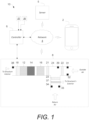
- FIG. 1 schematically shows an exemplary temperature control system 10 that may help implement the methodologies of the present disclosure.
- the system 10 may include various HVAC equipment components 8 configured to condition the interior air of the structure, i.e., to selectively heat and cool the interior air of the structure.
- the system 10 includes a controller 6 for controlling the HVAC equipment components 8.
- the system 10 may include a server 5, a network 4 and/or a mobile device 2.
- the methods and devices of the present disclosure may be practiced with the HVAC system 10 and/or as part of HVAC system 10.
- the server 5 may be directly communicatively connected to the controller 6 and the mobile device 2 or communicatively connected via the network 4.
- the server 5 may be: various embodiments of a computer including high-speed microcomputers, minicomputers, mainframes, and/or data storage devices.
- the server 5 preferably executes database functions including storing and maintaining a database and processes requests from the controller 6 and/or mobile device 2 to extract data from, or update, a database as described herein below.
- the server 5 may additionally provide processing functions for the mobile device 2 and the controller 6 as will become apparent to those skilled in the art upon a careful reading of the teachings herein.
- the HVAC controller 6 may be directly communicatively connected to one or more of the HVAC equipment components 8 including one or more sensors 31, 32, 33, and/or 34.
- the controller 6 is wirelessly connected to the one or more HVAC equipment components 8 via the network 4.
- the mobile device 2 may be physically or wirelessly connected to the network 4 and/or the controller 6 during selected periods of operation without departing from the teachings herein.
- Components of the system 10 are shown in FIG. 1 as single elements. Such illustration is for ease of description and it should be recognized that the system 10 may include multiple additional components in various embodiments without departing from the teachings herein.
- the controller 6 may be incorporated into the server 5.
- the exemplary HVAC system 10 shown in FIG. 1 includes an HVAC controller 6, which may be or may include a thermostat or a hydronic heat transfer system control in some embodiments.
- the HVAC controller 6 may be configured to communicatively interact with and control various components of the HVAC components 8.
- the HVAC controller 6 may be directly connected to the HVAC components 8 or connected via a network 4 which may be a locally based network or a wider network such as the Internet.
- the mobile device 2 is communicatively connected to the controller 6 so that a user may control the HVAC components 8 using the mobile device 2 via the controller 6.
- the HVAC components 8 include ventilation subsystem (16) and cooling subsystem (14).
- the HVAC components 8 may include a heating system 12, a fan, i.e., a blower, a humidification system 18 and/or any other HVAC components or systems, as desired such as an outside air damper 22 or intake damper 23.
- HVAC components include auxiliary heating and cooling equipment. Exhaust fans 37 and supply air fans 16, removing air from the structure, and moving air into the structure, respectively, may also be used in various embodiments.
- the HVAC components 8 primarily function as a forced air system although auxiliary HVAC components may be used in conjunction to supplement conditioning of the environment within the building.
- auxiliary heat may be provided by electrical resistive heaters, hot water radiant heat, boilers, and/or electric base board heaters in various embodiments.
- the heating system 12 and the cooling system 14 are combined in a forced air system; however, it is contemplated herein that the heating and cooling systems 12 and 14 may be separated.
- a heat pump system may be utilized separate from an air conditioning cooling system 14.
- the HVAC components 8 include any number of intake and outtake dampers.
- a filter 21, a first damper 22, and a second damper 23 are utilized consistent with the teachings herein.
- the damper 22 may be in communication with outside air and the fan 16 is in communication with one or more of the dampers 22 and 23 within a ducting 24, for example.
- the dampers 22 and 23 may be selectively actuatable as a group or individually in various embodiments.
- the HVAC components 8 may include cooling equipment, which may include more than one unit and/or more than one stage of cooling.
- the HVAC components 8 are selectively in gaseous communication with exterior ambient air and including operability to intake and/or vent exterior ambient air.
- the ventilation equipment may provide different levels of air movement as described herein below.
- the HVAC components 8 may include other units such as a humidifier unit, a dehumidifier unit, a UV filter unit and/or any other suitable HVAC unit and/or equipment as desired.
- the HVAC components 8 may include one or more sensors, such as an exterior ambient air temperature sensor 31, an exterior humidity sensor 32, a return temperature sensor 33, and/or a smoke detector 34.
- the sensors 31, 32, 33, and 34 may be directly or indirectly communicatively connected to the controller 6.
- the exterior ambient temperature sensor 31 is configured to measure a temperature of the outside air and, for example, may be mounted to an exterior of the building, or factory installed as part of the HVAC components 8.
- the exterior humidity sensor 32 may also be mounted external to ducting of the HVAC components 8 or factory installed as part of the HVAC components 8.
- An interior temperature sensor 35 measures a temperature of the interior air of the building.
- the sensor 35 may be internal to the controller 6 or external.
- an interior humidity sensor 36 measures the humidity of the interior air of the structure.
- the sensor 36 may be internal to the controller 6 or external.
- the controller 6 may obtain outside, i.e., exterior air temperature and/or humidity conditions through an online weather service or may be in communication with a building automation system having equivalent measuring functionality.
- predicted weather conditions may be utilized by the controller 6.
- the interior and exterior humidity sensors 36 and 32 are optional.
- sensors 33 and 34 are optional.
- the network 4 may be any suitable series of points or nodes interconnected by communication paths.
- the network 4 may be interconnected with other networks and contain sub network(s) such as, for example, a publicly accessible distributed network like the Internet or other telecommunications networks (e.g., intranets, virtual nets, overlay networks and the like).
- the network 4 may facilitate the exchange of data between and among the HVAC components 8, the HVAC controller 6, and the sensors 31, 32, 33, 34, 35 and 36; although in various embodiments the HVAC controller 6 may be directly connected to the HVAC components 8 and/or the sensors 31, 32, 33, 34, 35 and 36.
- the mobile device 2 may include one or more applications that the user may operate. Operation may include downloading, installing, turning on, unlocking, activating, or otherwise using the application in conjunction with the controller 6.
- the application may comprise at least one of an algorithm, software, computer code, executable instruction sets and/or the like, for example, mobile application software.
- the application may be utilized remotely through a website accessible through the world wide web.
- FIG. 2 shows the exemplary HVAC controller 6.
- the controller 6 includes a central processing unit (CPU) 50, random access memory (RAM) 52, input/output circuitry 54 for connecting peripheral devices such as a storage medium 56 to a system bus 60, a display adapter 58 for connecting the system bus 60 to a display device, a user interface adapter 62 for connecting user input devices such as various dials buttons and/or keypads, to the system bus 60, and a communication adapter 64 for connecting the controller 6 to the network 4.
- the memory 52 and storage medium 56 may be used to store any appropriate information such as HVAC control routines or code, historical performance data, HVAC system and/or HVAC controller parameters, one or more programmable schedules for changing HVAC system parameters over time, etc.
- the central processing unit 50 is preferably one or more general-purpose microprocessor or central processing unit(s) and has a set of control algorithms, comprising resident program instructions and calibrations stored in the memory 52 and executed to provide the desired functions.
- an application program interface is preferably executed by the operating system for computer applications to make requests of the operating system or other computer applications.
- the description of the central processing unit 50 is meant to be illustrative, and not restrictive to the disclosure, and those skilled in the art will appreciate that the disclosure may also be implemented on platforms and operating systems other than those mentioned.
- HVAC controller 6 may include any number of suitable components related to effecting control of the HVAC system 10.
- HVAC controller 6 may include a user interface 68 which may be graphical.
- the user interface 68 may include one or more displays, switches, and/or buttons that a user may actuate or otherwise control.
- a touchscreen display may be provided to display the user interface 68 and provide interaction therewith.
- one or more of a cooling device, heating equipment and/or ventilation equipment may be distinct systems controlled, either directly or indirectly, by the HVAC controller 6.
- the HVAC controller 6 may separately control each component 8.
- HVAC system parameters may include set points for heating, cooling, humidity, etc., modes for ventilation equipment, fan settings, and the like and as further described below.
- the HVAC controller 6 may include one or more internal sensors 65, such as a temperature sensor and/or a humidity sensor.
- the internal sensors 65 may be in addition to the sensors 35 and 36 and may be used for supplemental or redundancy purposes, as exemplary.
- the HVAC controller 6 may include one or more outputs configured to issue operation commands to the HVAC components 8. It is contemplated herein that the HVAC controller 6 may be configured to execute any method of the present disclosure.
- the HVAC controller 6 may be communicatively connected to one or more sensors connected external to a building structure and external to a housing of the controller 6. The connection may be via wire or via a wireless embodiment of the network 4.
- the HVAC controller 6 may maintain in its memory an operating schedule that may be used to control the HVAC system based upon time and/or day.
- the schedule may, for example, be a daily programmable schedule or any other schedule.
- the schedule may have a number of days and one or more time periods for each of at least some of the days.
- the nominal schedule may include an "occupied", an "unoccupied", and a "stand-by" time period for each of the days of a week.
- the schedule may have at least one set point associated with each of the one or more time periods.
- the schedule may be maintained in the memory 52, and may be modified by an end user in various embodiments.
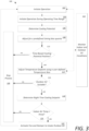
- FIG. 3 shows a control scheme 100 for operating the controller 6 and the HVAC components 8.
- the control scheme 100 is shown as discrete elements, such an illustration is for ease of description and it should be recognized that the functions performed by the control scheme 100 may be combined in one or more devices, e.g., implemented in software, hardware, and/or application-specific integrated circuitry (ASIC) and executed, in some cases, concurrently or in parallel. For example, monitoring of the various sensors may be executed concurrent with any number of execution steps.
- ASIC application-specific integrated circuitry
- the control scheme 100 is directed at operating efficiencies that can be gained from utilizing exterior ambient conditions to ventilate outside air into the structure and/or condition the interior environment. For example, during warm summer months, the coldest part of the day is typically in the early morning, such as between 4:00am and 6:00am. As set forth further below, during this early morning time, the controller 6 instructs one or more of the HVAC components 8 to operate to effect the intake of cool exterior air (and either passively or actively exhaust warm interior air) based upon exterior air conditions, interior air conditions, the usage of the HVAC components 8 during the previous day, and current settings of the HVAC components 8.
- the controller 6 may instruct the HVAC components 8 to intake cool exterior air, and optionally to exhaust warm interior air to decrease the temperature of the interior air of the structure to a temperature between the occupied heating set point and the occupied cooling set point of the HVAC components 8, as shown in FIG. 7 .
- the control scheme 100 is configured, in one exemplary implementation, to operate one or more of the HVAC components 8 using the controller 6 to condition the interior environment.
- the control scheme 100 is initiated at step 102 whereby the controller 6 operates the HVAC components 8 based upon a user's predefined or default operating parameters, and the results of a prior iteration of the control scheme 100.
- the control scheme 100 operates during cool mornings to proactively ventilate the building with cool exterior air based upon the operation of the HVAC components 8 during a previous period, e.g., during the previous day.
- the HVAC components 8 may transition between an occupied state and an unoccupied state.
- the control scheme 100 is operated only at a predetermined time range. While operating in an occupied state, the controller 6 typically operates to maintain interior air conditions at desired levels, for example, levels directed at maintaining comfortable conditions for occupants, e.g., a user-supplied set point. In one embodiment, while in the predetermined time range, the controller 6 executes the control scheme 100 to maintain interior air conditions at a second set of preferential conditions, which may be directed at a different set of objectives, e.g., energy conservation, equipment wear reduction, and/or improvement of indoor air quality.
- objectives e.g., energy conservation, equipment wear reduction, and/or improvement of indoor air quality.
- operation of one or more of the HVAC components 8 may be based upon operation that occurred during the previous period.
- the previous period may be, for example the previous day, i.e., the previous 24 hours.
- the previous period may be, for example, the previous day less any time duration during which the process 100 operated. For example, if the process 100 operated for two hours during the previous day (for example, from 4:00am to 6:00am), the previous period may be 22 hours (i.e., 24 hours minus 2 hours).
- the controller 6 may execute the control scheme 100 during a predefined operating time range.
- the controller 6 may then deactivate the control scheme 100 after or outside of the predefined operating time range.
- the operating time may be between 4:00am and 6:00am, for example.
- the operating time range may be user-defined.
- the operating time range may initiate at any suitable predefined time and may last for any suitable predefined duration.
- operating time may be defined based upon occurrence of an event.
- operating time may begin at any suitable predefined time, and not terminate until block 116 or block 120 of figure 3 is "no".
- operating time may be defined based upon historical trending of the coolest part of the day.
- a photocell could be utilized to estimate a time of dawn, and then, in turn, apply that time to the next day's predetermined start and stop times of the operating range.
- a start and stop time of the control scheme 100 may be determined based upon monitored exterior air temperature. For example, a time associated with a lowest temperature reading may be set as the start time or a predetermined time period before the monitored lowest temperature may be set as the start time and a predefined duration after the start time may be calculated for the stop time.
- FIGS. 5 and 6 graphically illustrate exemplary time ranges of exemplary operation of a cooling system and a heating system.
- FIG. 5 graphically shows a first sum of products of operational time and operational load of the cooling system and a second sum of products calculation for operational time and operational load of the heating system.
- the controller may difference the second sum of products from the first sum of products.
- a positive result indicates cooling potential, while a zero or negative result indicates no cooling potential.
- FIG. 6 shows an alternative to a sum of products calculation.
- cooling and heating equipment wherein cooling load output and heating load output are obtained as a function of operating load may be represented with respect to operating time.
- the controller may execute a first integral calculation for an operational load of the cooling system as a function of operational time over the first time range, execute a second integral calculation for an operational load of the heating system as a function of operational time over the first time range and then difference the second integral from the first integral. Similar to above, a positive result indicates cooling potential, while a negative result indicates no cooling potential.
- the control scheme 100 subtracts a time bias quanta from the cooling potential (cp).
- the time bias may be defined or set by the user. This time bias is subtracted from the cooling potential value to inhibit use of the control scheme 100 when only slightly more cooling than heating was observed in the previous period. In such a situation, it is likely that having the equipment cool the structure in the early morning may actually cause the heating function to be energized prior to the "heat of the day," which may be around 3:00pm.
- a user defined time bias may be adjusted or may be a default value, but as a default, that value may be set to 60 minutes.
- the control scheme 100 determines whether the entc value is positive or negative. If the entc value is zero or negative, the control scheme 100 stops the process 100 until the next time period 130. In other words, if the entc value is zero or negative (after being biased by the user defined time bias), then conditions may, undesirably, cause the controller 6 to effectuate the heating system 12 during the upcoming period, before the heat of the day, if the control scheme 100 were to ventilate the air in the building.
- the control scheme 100 is not operated to utilize the exterior air damper 22, and/or fan 16 to intake outdoor air and/or the exhaust fan(s) 37 to exhaust interior air thereby avoiding cooling the structure undesirably and avoiding inefficient use of the heating system 12 during the upcoming time period.
- the control scheme 100 measures indoor and outdoor air conditions.
- the control scheme 100 adjusts an exterior air temperature measurement using a user-defined or default temperature bias. Factoring in a temperature bias will cause the controller 6 to be less likely to determine that the exterior air is suitable to use for cooling the structure. The greater the temperature bias, the less likely the controller 6 will find the exterior air suitable.
- the temperature bias is added to compensate for electrical consumption of the equipment which operates during the control scheme 100 to cool the structure. For example, while running the fan(s) 16 alone consumes less electricity than running a number of the other HVAC components 8, e.g., compressors, condenser fans, etc., there is still energy consumption used by simply running the fan 16.
- the "break even" point for venting the exterior air is not when the exterior air temperature or enthalpy is slightly less than that of the interior air temperature or enthalpy, respectively, but is when the interior air temperature or enthalpy is significantly greater than the exterior air temperature or enthalpy, respectively, so that the cost to utilize the intake of exterior air and the exhausting of indoor air (either passively or actively) for cooling is profitable, in terms of the cost per kWh of heat transfer (or electricity consumption per kWh of heat transfer). Based on factors including, but not limited to, indoor air humidity set points, fresh air intake considerations, specific equipment characteristics, and the local cost of electricity, the optimal temperature or enthalpy difference may change. Enthalpy of the exterior air may be determined or estimated using exterior temperature and humidity measurements from the exterior temperature sensor 31 and the exterior humidity sensor 32 using known calculation techniques and/or modeling processes.
- the control scheme 100 analyzes the exterior ambient air to determine whether the exterior air is suitable.
- the determination of whether the exterior air is suitable may be based upon the use of industry standard enthalpy calculations, or temperature calculations, or some combination of the two. Specifically, the interior air condition and exterior air condition is measured. The suitability may be based upon interior and exterior air temperature and, optionally, humidity values, provided by the sensors, such as interior temperature sensor 35, exterior temperature sensor 31, interior humidity sensor 36, and exterior humidity sensor 32, network values, etc., or may simply utilize interior and exterior air temperature sensors 35 and 31, respectively, network values, etc.
- the control scheme is stopped at 130 and the controller 6 does not operate the damper(s) 22 and 23 and the fan 16 to intake exterior air, and optionally the exhaust fan(s) 37 to exhaust interior air.
- the controller 6 determines a night time cooling set point.
- the night time cooling set point is determined by subtracting the occupied heating set point, e.g., a "heating" set point on a conventional thermostat, from the occupied cooling set point, e.g., a "cooling" set point on a conventional thermostat, multiplying that value by a bias value (between 0 and 1, with a default of 0.67, for example), and then subtracting that product from the occupied cooling set point.
- the bias value may be used, for example, to affect the degree of pre-cooling within the building, with a larger biasing value resulting in more pre-cooling and a smaller biasing value resulting in less pre-cooling.
- ntcsp ocsp ⁇ ocsp ⁇ ohsp ⁇ udbv
- enthalpy values could be entered in place of temperature values to determine the ntcsp.
- the value of the ntcsp could be expressed in terms of enthalpy rather than simple temperature.
- indoor air enthalpy and outdoor air enthalpy could be used rather than simple temperatures.
- control scheme 100 has determined the ntcsp, it compares the ntcsp with the interior air temperature. If the interior air temperature is less than or equal to the ntcsp, then the control scheme 100 terminates all sequences 130.
- the control scheme 100 energizes, for example, a relay, triac output, network signal, etc., which will, at least, energize equipment which causes cool outdoor air to enter the building, e.g., the fan 16, and open the exterior air damper 22 (also known as the fresh air damper 22).
- the control scheme 100 may energize any connected exhaust equipment such as the exhaust fan(s) 37, which may remove air from the building, to help facilitate economization of the primary heating, cooling, and ventilation equipment.
- the relay, triac output, network signal, etc. will remain active until conditions change in blocks 110, 116, or 120.
- the controller will terminate step 122 if the controller 6 is transitioned to an occupied state.
- the controller 6 will terminate step 122 if a current time is outside of the predefined time range.
- the controller 6 may transition the one or more of the HVAC components 8 to a stopped operating state 130.
- the control scheme 100 may be configured to transition out of step 130 after a predefined duration of time or upon occurrence of an event.
- FIG. 4 shows a control scheme 200 for operating the controller 6 and the HVAC components 8 illustrating operation of the system 10 using enthalpy values determined from temperature and humidity measurements.
- the control scheme 200 is shown as discrete elements, such an illustration is for ease of description and it should be recognized that the functions performed by the control scheme 200 may be combined in one or more devices, e.g., implemented in software, hardware, and/or application-specific integrated circuitry (ASIC) and executed, in some cases, concurrently or in parallel. For example, monitoring of the various sensors may be executed concurrent with any number of execution steps.
- ASIC application-specific integrated circuitry
- the control scheme 200 is directed at operating efficiencies that can be gained from utilizing exterior ambient conditions to ventilate outside air into the structure and/or condition the interior environment. For example, during warm summer months, the coldest part of the day is typically in the early morning, such as between 4:00am and 6:00am. As set forth further below, during this early morning time, the controller 6 instructs one or more of the HVAC components 8 to operate to effect the intake of cool exterior air (and either passively or actively exhaust warm interior air) based upon exterior air conditions, interior air conditions, the usage of the HVAC components 8 during the previous day, and current settings of the HVAC components 8.
- the controller 6 may instruct the HVAC components 8 to intake cool exterior air, and optionally to exhaust warm interior air to decrease the temperature of the interior air of the structure to a temperature between the occupied heating set point and the occupied cooling set point of the HVAC components 8, as shown in FIG. 7 .
- the control scheme 200 is configured, in one exemplary implementation, to operate one or more of the HVAC components 8 using the controller 6 to condition the interior environment.
- the control scheme 200 is initiated at step 202 whereby the controller 6 operates the HVAC components 8 based upon a user's predefined operating parameters, e.g., set points, and the results of a prior iteration of the control scheme 200.
- the control scheme 200 operates during cool mornings at predefined or determined times to proactively ventilate the building with cool exterior air based upon the operation of the HVAC components 8 during a previous period, e.g., during the previous day.
- the controller 6 may execute the control scheme 200 during a predefined operating time range, a predefined time duration having a determined start time based upon prior measured exterior air conditions and/or photocell measurements.
- control scheme 200 determines a cooling potential of the interior air based upon the previous period, e.g., the previous day, similar to step 106 described herein above with respect to control scheme 100.
- the control scheme 200 subtracts a time bias or buffer value from the determined cooling potential (cp). This time bias is subtracted from the cooling potential value to prohibit use of the control scheme 200 when only slightly more cooling than heating was observed in the previous period.
- the control scheme 200 determines whether the entc value is positive or negative or zero.
- the entc value is the difference between the cooling potential value and the time bias or buffer value. If the entc value is zero or negative, the control scheme 200 stops the process 200 until the next time period by transitioning the control scheme 200 to a stop state 230.
- the control scheme 200 measures interior and exterior air conditions including an exterior temperature and exterior humidity.
- the control scheme 200 determines the exterior enthalpy using the monitored exterior air conditions including temperature and humidity. Enthalpy of the exterior air may be determined or estimated using exterior temperature and humidity measurements from the exterior temperature sensor 31 and the exterior humidity sensor 32 using known calculation techniques and/or modeling processes.
- the control scheme 200 adjusts the determined enthalpy value using a buffer value. Factoring in a buffer will cause the controller 6 to be less likely to determine that the exterior air is suitable to use for cooling the structure. The greater the buffer value, the less likely the controller 6 will find the exterior air suitable.
- the buffer value is added to compensate for electrical consumption of the equipment which operates during the control scheme 200 to cool the structure. For example, while running the fan(s) 16 alone consumes less electricity than running a number of the other HVAC components 8, e.g., compressors, condenser fans, etc. in combination with each other, there is still energy consumption used by simply running the fan 16.
- the "break even" point for venting the exterior air is not when the exterior air temperature or enthalpy is slightly less than that of the interior air temperature or enthalpy, respectively, but is when the interior air temperature or enthalpy is significantly greater than the exterior air temperature or enthalpy, respectively, so that the cost to utilize the intake of exterior air and the exhausting of indoor air (either passively or actively) for cooling is profitable, in terms of the cost per kWh of heat transfer (or electricity consumption per kWh of heat transfer). Based on factors including, but not limited to, indoor air humidity set points, fresh air intake considerations, specific equipment characteristics, and the local cost of electricity, the optimal temperature or enthalpy difference may change.
- the control scheme 200 analyzes the exterior ambient air to determine whether the exterior air is suitable. The determination of whether the exterior air is suitable may be based upon the use of industry standard enthalpy calculations, or temperature calculations, or some combination of the two. In one embodiment, the interior humidity value and exterior humidity values are compared. If the controller 6 determines that the exterior air is not suitable for intake, e.g., interior conditions are preferable to exterior conditions, then the control scheme 200 is stopped at 230 and the controller 6 does not operate the damper(s) 22 and 23 and the fan 16 to intake exterior air, and optionally the exhaust fan(s) 37 to exhaust interior air.
- the controller 6 determines a night time enthalpy cooling set point similarly to the process described herein above with respect to control scheme 100 only using enthalpy values and not exclusively temperature values.
- the night time cooling set point 218 is determined by subtracting the occupied enthalpy heating set point, from the occupied enthalpy cooling set point, and then multiplying that value by a bias value (between 0 and 1, with a default of 0.67, for example), and then subtracting that product from the occupied enthalpy cooling set point.
- a bias value between 0 and 1, with a default of 0.67, for example
- control scheme 200 has determined the ntcsp, it compares the ntcsp with the interior enthalpy. If the interior air enthalpy is less than the ntcsp, then the control scheme 200 terminates all sequences by transitioning to block 230.
- the control scheme 200 energizes, for example, a relay, triac output, network signal, etc., which will, at least, energize equipment which causes cool outdoor air to enter the building, e.g., the fan 16, and open the exterior air damper 22.
- the process may energize any connected exhaust equipment, which may remove air from the building, to help facilitate economization of the primary heating, cooling, and ventilation equipment.
- the relay, triac output, network signal, etc. will remain active until conditions change in blocks 210, 216, or 220.
- the controller will terminate step 222 if the controller 6 is transitioned to an occupied state.
- the controller 6 will terminate step 222 if a current time is outside of the predefined time range.
- the controller 6 may transition the one or more of the HVAC components 8 to a stopped operating state 230.
- the control scheme 200 may be configured to transition out of step 230 after a predefined duration of time or upon occurrence of an event.
- FIG. 7 graphically shows operation of the HVAC system for venting exterior air into a structure with respect to indoor temperature, while outdoor air is suitable for cooling 116.
- specific condition ranges related to the structure's interior and monitored exterior temperature result in venting exterior air to the interior of the structure.
- venting of the exterior air to the inside will occur when: (1) the time biased cooling potential is positive; and (2) the indoor temperature is greater than a cooling set point associated with an unoccupied status of the structure, i.e., (second time range).
- the criteria for venting of the exterior air to the inside is satisfied in zone 300.
- the controller 6 may utilize a thermostat of the HVAC components 8.
- a capacitor may be set to charge when the Y1 terminal is activated, with a resistor inline with the capacitor, which acts as a regulator for the current.
- the same capacitor could also be charged when the Y2 terminal is activated, which would also have an inline "regulator” resistor.
- the heating terminals could also have a capacitor which is charged via the W1 and W2 terminals, with "regulating" resistors in-line. The charges of the two capacitors would be discharged via a short, which is regulated by a (high value) resistor.
- the total charges of each of the two capacitors could be compared via an integrated circuit (IC) to determine the cooling potential (as set forth above) for the upcoming time period.
- IC integrated circuit
- the time bias could be incorporated by adding a potentiometer to the circuit.
- some level of circuit integration could be added. For example, a time clock of the thermostat may be incorporated into the process. Similarly, the occupied set points (or at least the lowest cooling set point) may be incorporated into the process.
- interior humidity and exterior humidity sensors are optional, and a provision may be made to utilize both or only one type of humidity sensor.
- the system 10 utilizes a default, predefined humidity reading as a reference marker to compare measurements from the exterior humidity sensor.
- the system 10 may be configured to assume that the interior humidity is at a first predefined level under a first set of criteria, e.g., a reading from the exterior humidity sensor after running the control scheme 100 for at least a first time period.
- a first set of criteria e.g., a reading from the exterior humidity sensor after running the control scheme 100 for at least a first time period.
- Another example may assume that the interior humidity is simply at a predefined level.
- the system 10 could compare the assumed humidity value and the measured value until the exterior humidity levels exceed 50% relative humidity, at which point the assumed interior humidity level would stay at 50%, while the actual relative humidity value for the exterior humidity levels would be reflected in the system's 10 calculations.
- the control scheme 100 may stop if the exterior humidity is above and/or below a predetermined threshold.
- ntcsp On thermostat embodiments having a switch to select "cool” (only) or “heat” (only), there could be a calculated or user-defined ntcsp (see above).
- the calculated ntcsp could use a user defined temperature offset value which may be set via programming the thermostat, or may simply use a default value of a certain number of degrees less than the lowest cooling set point on the thermostat.
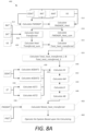
- FIG. 8A shows a block diagram illustrating an exemplary process 400 for controlling the system 10 based upon a calculated anticipated heat energy transfer metric.
- FIG. 8A may show a specific order of method steps, the order of the steps may differ from what is depicted.
- the methods or steps shown in the flowcharts and described in the accompanying text are not constrained to a particular order or sequence. In various embodiments, some of the steps thereof can occur or be performed concurrently or with partial concurrence and not all the steps have to be performed in a given implementation depending on the requirements of such implementation. Further, the order or sequence of any process or method steps may be varied or re-sequenced according to alternative embodiments. Other substitutions, modifications, changes, and omissions may be made in the design, operating conditions and arrangement of the exemplary embodiments without departing from the scope of the present disclosure. All such variations are within the scope of the disclosure.
- FMOADP (70 °F - 55 °F) / (70 °F - 50 °F), which equals a value of 0.75, meaning that the outdoor air damper 22 is open 75%, where a '1' value is defined as completely open and a '0' value is defined as closed.
- a discharge air temperature may be utilized to determine FMOADP instead of the MAT variable as one skilled in the art will recognize upon a careful reading of the teachings herein.
- the FMOADP could be calculated and trended (based on time or time in different states/values) for use later. For example, specific calculations of FMOADP at noon and at 2pm, may be trended to determine position at 1pm or 3pm. In one embodiment, the FMOADP may be used in calculating the energy (or heat) added to, or removed from the structure via the "fresh air intake", or intake of outdoor air.
- heat transfer due to FMOADP and ventilation status may be calculated when considering temperatures.
- historical heat transfer rates due to the intake of outdoor air may be used to predict the heat transfer going forward.
- the heat transferred during the last same day of the previous week could be used to determine another day's anticipated value, or may begin as the average heat transferred the last same day of the week and month for the first year, and/or then in later years, the average heat transferred on the same day of the week and month in preceding years.
- a church might have nominal load demand on every day of the week except Sunday. Basing the next day's predicted cooling potential based on the last Sunday's actual load demand, or on the same Sunday from the previous year's load demand may be beneficial instead of using the prior day's load demand.
- a "VS constant" can be multiplied by each individual climate control equipment's value for VS, such that the value of VS for each individual climate control equipment shall be in proportion to its volumetric flow rate in relation to all other climate control equipment. For example: If two pieces of climate control equipment are used, one capable of moving 4,000 CFM (6796 m 3 /h) (unit #1), and another capable of moving 8,000 CFM (13592 m 3 /h) (unit #2), then the VS constant for unit #1 would be 0.5, and the VS constant for unit #2 would be 1.
- FMOADP_heat 1 * (60 °F - 70 °F) * 0.1, which reduces to - 1 °F (-18.3°C).
- the system 10 may determine FMOADP_Heat_sum.
- FMOADP_Heat_sum represents a heat transferred (based on the FMOADP_heat metric), resulting from venting outdoor air into, and indoor air out of, the building structure for the entire period being measured (e.g., a whole day, 22 hours, one week, etc.).
- FMOADP_Heat_sum represents a heat transferred (based on the FMOADP_heat metric), resulting from venting outdoor air into, and indoor air out of, the building structure for the entire period being measured (e.g., a whole day, 22 hours, one week, etc.).
- multiple climate control equipment i.e.
- FMOADP_Heat_sum can be summed with the FMOADP Heat sum of the other networked and/or controlled systems, however, the FMOADP_heat calculation of each individual unit would likely need to have a "VS constant" (as described above) applied to the FMOADP_heat value for each individual unit.
- the system 10 may calculate a heat transfer metric (HeatTransferred) due to a HVAC unit's operation of mechanical heating or cooling (e.g. using gas burners, refrigerant based systems, etc.), iteratively at predetermined sampling intervals, e.g., at a time interval ti, as follows, while understandably similar calculations could be made by replacing the temperature variables for enthalpy variables and modifying the equations slightly.
- the operation of the mechanical cooling or mechanical heating is preferably considered to ascertain the heat transfer into or out of a structure during a period of time.
- the energy transferred may be fairly easily calculated, however, in a situation where the volumetric air flow is unknown, and for the purposes of the disclosure, the total heat transfer, as a result of a HVAC unit's mechanical operation, (e.g., use of gas burners for heating, refrigeration based cooling systems, compressors, etc.) may require the formation of a new metric.
- FIG. 8B shows an alternative process 400' for implementation in the system 10 without sensors 31, 33, 38, and 39 being used for calculating HeadTransferred at step 418'.
- FMOADP_Heat_sum is then calculated at step 416' based upon a FMOADP_heat having a 0 value. As one skilled in the art may understand after considering the teachings disclosed herein that the units of measurement will change from degree-minutes to minutes.
- HeatTransferred_sum ⁇ a b HeatTransferred t dt
- a separate HeatTransferred_sum may be determined for each system and then may be added together.
- the process 400 calculates a Total_heat_transferred (at step 422) by adding HeatTransferred_sum with FMOADP _Heat_sum.
- Total_heat_transfered then represents a total °F-minutes (°C-minutes) of heat transferred into the structure by the HVAC unit during the time period (i.e. 22 hours, 24 hours, one week, etc.).
- the heat energy was transferred into the structure (the heating system 12 was operated to introduce heat into the structure). If the value would have been negative, then heat energy would have been transferred out of the structure by the system 10 via one or more of the components, e.g., the ventilation system 16.
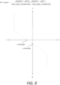
- the total_heat_transferred can be used to determine the slope M 440, which in turn can be used to predict the next period's heat transfer (NTotal_heat_transferred 450).
- the total_heat_transferred for at least two historic time periods can be calculated (i.e. two days, two 6 hour periods, two weeks, or whatever period is determined to be most effective in predicting the next period's heat transfer desired).
- the total_heat_transferred for the first historic time period could be total_heat_transferred_1, and for the second historic time period could be called total_heat_transferred_2, and so on, as determined in step 424.
- the process 400 further includes determining an average outdoor air temperature for a period (AODAT) at steps 430 and 432.
- AST ⁇ a b f x dx / b ⁇ a
- Total_heat_transferred HeatTransferred_sum + FMOADP_Heat_sum.
- a 22 hour, 24 hour, period may be used to define a "day” or “period”, however it should be understood that when determining a slope of a graph, it may be beneficial to use different time periods.
- HeatTransferred_sum and FMOADP_Heat_sum can use identical time periods for determining Total_heat_transfered, and any equations that combine HeatTransferred_sum, FMOADP_Heat_sum, Total_heat_transferred, AODAT, and AST will likely require that identical time periods be used, it should also be understood that in the application of determining the slope ((AODAT 2 - AST 2 ) - (AODAT 1 - AST 1 )) / (Total_heat_transferred 2 - Total_heat transferred 1 ) that smaller time periods may be more suitable, e.g., a 6 hour time period., although the disclosure herein contemplates that various time periods may be utilized consistent with the teachings herein.
- the process 400 calculates a slope 'M' based upon two or more iterations of AODAT, AST, and the Total_heat_transferred calculations at step 440.
- the system 10 may apply various statistical conditioning or averaging of the slope M to maintain consistency. Because the slope of the graph relates Total_heat_transferred to (AODAT - AST) it should remain fairly constant, since the slope is directly related to the R-value of the structure's envelope (as well as other minor factors- in some cases).
- the difference between the beginning of the time span and the end of the time span may be defined as a week (i.e., 7 days), while M, could be recalculated every six hours, or once a day, for example.
- M could be recalculated every six hours, or once a day, for example.
- B is a y-intercept used on FIG. 9 that illustrates a relationship of Total_heat_transferred to (AODAT - AST).
- a NTotal_heat_transferred value is determined.
- weather predictions may be utilized in conjunction with the AM slope to determine the next period's (e.g., day), anticipated/projected Total_heat_transferred, i.e., NTotal_heat_transferred.
- the AM slope permits incorporating set point data into the equation for determining the next day's anticipated/projected Total_heat_transferred. For example: a church may not have need for cooling any day except Sunday.
- a predicted space temperature may be determined by taking all relevant data regarding scheduled set point information (which correlates space temperature set points with times), default space temperature set points, historical user set point data, etc.
- scheduled set point information which correlates space temperature set points with times
- default space temperature set points e.g., 1 z x i / Z
- ASTSP ⁇ a b f x dx / b ⁇ a
- PAODAT is the predicted average outdoor air temperature. In one embodiment, this value may be determined from an average of the predicted outdoor air temperatures (PODAT) over a future time period. In one embodiment, PAODAT may be based upon forecasted predictions from subscription or governmental sources, e.g., weather forecasting information. In one embodiment, PAODAT may simply be based upon a rolling average temperature period over a predefined number of time periods, e.g., days. As there are many ways to determine PAODAT, which one skilled in the art will recognize upon a careful reading of the disclosure herein may understand there are many ways to determine PAODAT.
- PAST is the predicted average space temperature for the following time period (i.e. the next day or next 12 hours, etc.). There are many ways to calculate PAST. In one embodiment of the invention, PAST may be equal to the AST of a chosen historical time period, such as the day before, or the same day of the previous week. The limitation of setting PAST equal to a previous time period's AST is that this method does not take into account the future set point temperature schedule.
- PAST is a function of predicted outdoor air temperature (PODAT) and the future set point temperature.
- PODAT predicted outdoor air temperature
- the space temperature could be plotted versus the outdoor air temperature under different set point temperature conditions. From this data, functions to represent ST versus ODAT, under different set point conditions, could be determined. Any data that derives a non-functional result would be negated or accounted for differently.
- the PODAT could be substituted for the ODAT in the functions.
- PAST may be calculated based upon Newton's "Law of Cooling (Warming).”
- Newton's “Law of Cooling” states that the rate at which the temperature changes of one body is proportional to the difference in the temperatures of the body and the environment.
- the environment includes the outside as well as the effects of internal heat sources, such as computers, lights, etc..
- both k and C can be determined. Two data points are used to determine how the structure naturally warms. Using historical data ( t 1 , ST 1) and ( t 2, ST 2) where the numbers 1 and 2 indicate first and second data points while YODAT1 remains constant.
- the value of k is a value dependent on the thermal characteristics of the structure.
- the value C would be calculated with different values of YODAT1 and ST1.
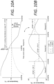
- FIGS. 10A and 10B illustrate, there may be a period of natural warming, a steady period (temperature at STSP), and a period of natural cooling.
- t 1 t 2 YODAT 1 t 2 ⁇ t 1 ⁇ C k e k t 2 ⁇ e k t 1 ⁇ t 2 t 3
- STSP dt STSP t
- the predicted average space temperature (PAST) for the next period, e.g. the next day, could be extracted from a user-supplied temperature schedule, default temperature schedule, historical user entry data, a combination of these, the equations given herein above, etc.
- the NTotal_heat_Transferred value is that which the system 10 would try to achieve in order to condition the structure in preparation of the next day, however, upper and lower limits may inhibit the value being too high or low, and/or upper and lower limits may inhibit the operations to achieve NTotal_heat_Transferred in order to keep the space temperature within reasonable limits.
- the appropriate limits on the operations of the systems may be understood by one skilled in the art, when considering the teachings herein disclosed.
- volumetric flow rates of the system 10 are known in real units of measure, then industry standard calculations could be made to determine the real value, in terms of real units of measure, of heat transfer. Also an amount of energy produced inside the structure due to people, computers, lights, etc., which is referred to as IHEPIS (the value of the x-intercept of the graph in FIG. 9 multiplied by -1) could be calculated using real units of measure.
- IHEPIS the value of the x-intercept of the graph in FIG. 9 multiplied by -1
- the R-value of the structure's envelope could be computed using the slope of (AODAT - AST) / Total_heat_transferrred, although if for instance a window was left open, the resulting heat transfer would affect the calculated R-value.
- k could be used to calculate the effective thermal capacity of the structure.
- the system 10 may operate various components to effect ventilation, cooling, and/or heating at step 460 based upon the calculated NTotal_heat_Transferred value.
- the following table shows the AODAT, AST, and total_heat_transferred over three days (i.e. three time periods). Please note that this example may not be typical, but rather is given for illustrative purposes.
- the system would cool the structure on Thursday, transferring -267°F-min (-166.1 °C/min) of heat energy to do so. Therefore, during the time when conditions were optimal (usually from 4-6am), the system would bring in cool outdoor air for a certain amount of time until the total_heat_transferred reached the -267°F-min (-166.1 °C/min) necessary to meet the day's predicted cooling requirements.
- the system could also activate mechanical cooling (i.e. compressors, refrigeration systems, etc.) to cool the structure. If NTotal_heat_transferred were a positive value, then the system could heat the structure instead of cooling it. If opportune, this could be done during the heat of the day by bringing in outdoor air and exhausting indoor air, or alternatively, with mechanical heating (i.e. heat pumps, etc.) if conditions warranted such action.
- IHEPIS The internal heat energy produced inside a structure, due to things like lighting, computers, etc. is referred to herein as: "IHEPIS”.
- space temperature set point may be used rather than space temperature to operate many of the functions, calculations, and equations disclosed herein.
Landscapes
- Engineering & Computer Science (AREA)
- Chemical & Material Sciences (AREA)
- Combustion & Propulsion (AREA)
- Mechanical Engineering (AREA)
- General Engineering & Computer Science (AREA)
- Signal Processing (AREA)
- Physics & Mathematics (AREA)
- Fuzzy Systems (AREA)
- Mathematical Physics (AREA)
- Human Computer Interaction (AREA)
- Air Conditioning Control Device (AREA)
Claims (9)
- Procédé pour faire fonctionner un système de régulation de température (10) comportant un sous-système de ventilation (16) et un sous-système de refroidissement (14), le procédé comprenant :la surveillance d'une température intérieure d'une structure ;la surveillance d'une température extérieure de l'air ambiant à l'extérieur de la structure ;la définition d'une première plage horaire et d'une seconde plage horaire, dans lequel la seconde plage horaire comprend une durée plus courte que la première plage horaire ;l'association d'un ou plusieurs paramètres de fonctionnement du sous-système de ventilation (16) et du sous-système de refroidissement (14) à la première plage horaire ;l'association d'un ou plusieurs paramètres de fonctionnement du sous-système de ventilation (16) et du sous-système de refroidissement (14) à la seconde plage horaire ;la surveillance du temps de fonctionnement et la charge de fonctionnement du sous-système de refroidissement (14) pendant la première plage horaire caractérisée par ;la prévision d'une température d'espace et d'une température de l'air extérieur pendant une période de temps ultérieure ; etla commande du sous-système de ventilation (16) pendant la seconde plage horaire sur la base du temps de fonctionnement et de la charge de fonctionnement surveillés du sous-système de refroidissement (14) pendant la première plage horaire, des températures intérieure et extérieure surveillées, de la température d'espace prévue, de la température d'air extérieur prévue, et de l'un ou plusieurs paramètres de fonctionnement du sous-système de refroidissement (14) associés à la seconde plage horaire.
- Procédé selon la revendication 1, dans lequel la prévision de la température d'espace est prédite sur la base de la température intérieure et extérieure surveillée d'une ou plusieurs périodes de temps définies antérieurement, d'un ou plusieurs points de consigne de température fournis par l'utilisateur associés à l'une ou plusieurs périodes de temps définies antérieurement et de la température d'air extérieur prévue.
- Procédé selon la revendication 1, dans lequel la prévision de la température d'espace est calculée en utilisant :
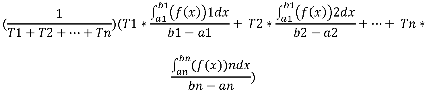 x représente la température d'air extérieur prévue (POADT),(f(x))1, (f(x))2... (f(x))n représentent une fonction de la température d'espace,T1, T2...Tn représentent des intervalles de temps,n représente un nombre total d'intervalles de consigne pendant la période de temps,b1, b2, bn représentent une POADT de fin de l'intervalle, eta1, a2, an représentent une POADT de début de l'intervalle.
 - Procédé selon la revendication 1, comprenant en outre :la surveillance d'une température d'air d'alimentation et d'une température d'air de retour ;la surveillance d'un état de fonctionnement d'un système de ventilation ;la surveillance d'une température d'espace ;le calcul d'une première température d'espace moyenne pendant une première période de temps sur la base de la température d'air intérieur surveillée ;le calcul d'une seconde température d'espace moyenne pendant une seconde période de temps sur la base de la température d'air intérieur surveillée ;le calcul d'une première température d'air extérieur moyenne pendant la première période de temps sur la base de la température d'air extérieur surveillée ;le calcul d'une seconde température d'air extérieur moyenne pendant la seconde période de temps sur la base de la température d'air extérieur surveillée ; etla commande supplémentaire du système de régulation de température sur la base de la température de l'air d'alimentation, de la température de l'air de retour et de la température d'espace surveillée ; l'état de fonctionnement du système de ventilation, la première température d'espace moyenne calculée, la seconde température d'espace moyenne calculée, la première température d'air extérieur moyenne calculée et la seconde température d'air extérieur moyenne calculée.
- Procédé selon la revendication 4, dans lequel le système de régulation de température (10) comprend en outre un registre d'air extérieur (22) ; et dans lequel le procédé comprend en outre :la surveillance d'une température d'air mélangé, dans lequel la température d'air mélangé est surveillée à l'intérieur d'un boîtier du régulateur de température, en aval d'une alimentation en air de retour et en aval de l'air extérieur ;le calcul d'une position d'ouverture du registre d'air extérieur (22) sur la base de la température d'air de retour surveillée, de la température d'air mélangé surveillée et de la température extérieure surveillée ; etla commande supplémentaire du système de régulation de température (10) sur la base de la position d'ouverture surveillée.
- Procédé selon la revendication 5, dans lequel la commande du système de régulation de température (10) comprend en outre :de manière itérative, à des périodes de temps définies, le calcul de somme, pour un premier résultat, d'un produit de l'état de fonctionnement surveillé du système de ventilation (16) avec une différence entre la température de l'air d'alimentation et la température de l'air de retour surveillée et une différence d'un produit de l'état de fonctionnement surveillé du système de ventilation (16) et la position d'ouverture calculée du registre d'air extérieur (22) avec une différence entre la température extérieure surveillée et la température de l'air de retour surveillée ;la commande supplémentaire du système de régulation de température (10) sur la base du calcul de somme itérative ;de manière itérative, à des périodes de temps définies, le calcul de somme, pour un second résultat, d'un produit de l'état de fonctionnement surveillé du système de ventilation (16) et de la position d'ouverture surveillée du registre d'air extérieur (22) avec une différence entre la température extérieure surveillée et la température de l'air de retour surveillée ; etla commande supplémentaire du système de régulation de température (10) sur la base du calcul de somme itérative.
- Procédé selon la revendication 6, dans lequel la commande du système de régulation de température (10) comprend en outre :la commande supplémentaire du système de régulation de température (10) sur la base d'une somme du premier résultat et du second résultat ; etle calcul de la moyenne d'une différence entre la première température de l'air extérieur moyenne et la première température d'espace moyenne soustraite d'un produit de la somme du premier résultat et du second résultat et d'une variable M calculée par : une différence entre la différence de la seconde température de l'air extérieur moyenne pendant la seconde période de temps et la seconde température d'espace moyenne pour la seconde période de temps et la différence entre la première température de l'air extérieur moyenne pendant la première période de temps et la première température d'espace moyenne pendant la première période de temps divisée par : une différence entre la somme du premier résultat et du second résultat calculée à la seconde période de temps et la somme du premier résultat et du second résultat calculée à la première période de temps.
- Procédé selon la revendication 1, comprenant en outre :la surveillance d'une température d'air mélangé, dans lequel la température d'air mélangé est surveillée à l'intérieur d'un boîtier du régulateur de température, en aval d'une alimentation d'air de retour et en aval de l'air extérieur ;le calcul d'une position d'ouverture du registre d'air extérieur (22) sur la base de la température de l'air de retour surveillée, de la température de l'air mélangé surveillée et de la température extérieure surveillée ;la commande supplémentaire du système de régulation de température (10) sur la base de la position calculée du registre.
- Procédé selon la revendication 1, comprenant en outre :l'estimation de l'énergie thermique produite à l'intérieur de la structure sur la base des températures de l'air extérieur surveillées, des températures de l'air intérieur surveillées et de l'état de fonctionnement du système de régulation de température ; etla commande supplémentaire du système de régulation de température (10) sur la base de l'énergie thermique estimée produite.
Applications Claiming Priority (2)
| Application Number | Priority Date | Filing Date | Title |
|---|---|---|---|
| US15/231,943 US10871756B2 (en) | 2014-08-26 | 2016-08-09 | Temperature control system and methods for operating same |
| PCT/US2016/052556 WO2018031052A1 (fr) | 2016-08-09 | 2016-09-19 | Système de régulation de température et ses procédés de fonctionnement |
Publications (4)
| Publication Number | Publication Date |
|---|---|
| EP3497377A1 EP3497377A1 (fr) | 2019-06-19 |
| EP3497377A4 EP3497377A4 (fr) | 2019-11-20 |
| EP3497377C0 EP3497377C0 (fr) | 2023-11-22 |
| EP3497377B1 true EP3497377B1 (fr) | 2023-11-22 |
Family
ID=61163095
Family Applications (1)
| Application Number | Title | Priority Date | Filing Date |
|---|---|---|---|
| EP16912865.9A Active EP3497377B1 (fr) | 2016-08-09 | 2016-09-19 | Système de régulation de température et ses procédés de fonctionnement |
Country Status (3)
| Country | Link |
|---|---|
| EP (1) | EP3497377B1 (fr) |
| CA (1) | CA3043996C (fr) |
| WO (1) | WO2018031052A1 (fr) |
Families Citing this family (126)
| Publication number | Priority date | Publication date | Assignee | Title |
|---|---|---|---|---|
| US9411327B2 (en) | 2012-08-27 | 2016-08-09 | Johnson Controls Technology Company | Systems and methods for classifying data in building automation systems |
| US10175681B2 (en) | 2014-05-01 | 2019-01-08 | Johnson Controls Technology Company | High level central plant optimization |
| US11953865B2 (en) | 2015-04-23 | 2024-04-09 | Johnson Controls Tyco IP Holdings LLP | HVAC controller with predictive cost optimization |
| US10186889B2 (en) | 2015-10-08 | 2019-01-22 | Taurus Des, Llc | Electrical energy storage system with variable state-of-charge frequency response optimization |
| US10534326B2 (en) | 2015-10-21 | 2020-01-14 | Johnson Controls Technology Company | Building automation system with integrated building information model |
| US12196437B2 (en) | 2016-01-22 | 2025-01-14 | Tyco Fire & Security Gmbh | Systems and methods for monitoring and controlling an energy plant |
| US11268732B2 (en) | 2016-01-22 | 2022-03-08 | Johnson Controls Technology Company | Building energy management system with energy analytics |
| US11774920B2 (en) | 2016-05-04 | 2023-10-03 | Johnson Controls Technology Company | Building system with user presentation composition based on building context |
| US20180004171A1 (en) | 2016-06-30 | 2018-01-04 | Johnson Controls Technology Company | Hvac system using model predictive control with distributed low-level airside optimization and airside power consumption model |
| US11789415B2 (en) | 2016-06-30 | 2023-10-17 | Johnson Controls Tyco IP Holdings LLP | Building HVAC system with multi-level model predictive control |
| US20180032969A1 (en) | 2016-07-27 | 2018-02-01 | Johnson Controls Technology Company | Systems and methods for automated diagnostics of hvac systems |
| TWI747937B (zh) | 2016-08-22 | 2021-12-01 | 美商江森自控科技公司 | 用以控制冷凍系統之系統及方法 |
| US11238547B2 (en) | 2017-01-12 | 2022-02-01 | Johnson Controls Tyco IP Holdings LLP | Building energy cost optimization system with asset sizing |
| US10095756B2 (en) | 2017-02-10 | 2018-10-09 | Johnson Controls Technology Company | Building management system with declarative views of timeseries data |
| US10515098B2 (en) | 2017-02-10 | 2019-12-24 | Johnson Controls Technology Company | Building management smart entity creation and maintenance using time series data |
| US11994833B2 (en) | 2017-02-10 | 2024-05-28 | Johnson Controls Technology Company | Building smart entity system with agent based data ingestion and entity creation using time series data |
| US10845064B2 (en) | 2017-02-15 | 2020-11-24 | Johnson Controls Technology Company | Heating, ventilation, and air conditioning control system |
| US10706375B2 (en) | 2017-03-29 | 2020-07-07 | Johnson Controls Technology Company | Central plant with asset allocator |
| US11675322B2 (en) | 2017-04-25 | 2023-06-13 | Johnson Controls Technology Company | Predictive building control system with discomfort threshold adjustment |
| US10816235B2 (en) | 2017-04-27 | 2020-10-27 | Johnson Controls Technology Company | Building energy system with predictive control of battery and green energy resources |
| US10146237B2 (en) | 2017-04-28 | 2018-12-04 | Johnson Controls Technology Company | Smart thermostat with model predictive control |
| US11274849B2 (en) | 2017-04-28 | 2022-03-15 | Johnson Controls Tyco IP Holdings LLP | Smart thermostat with model predictive control and demand response integration |
| US11022989B2 (en) | 2017-05-12 | 2021-06-01 | Air Distribution Technologies Ip, Llc | Air distribution systems and methods |
| US12085296B2 (en) | 2017-05-26 | 2024-09-10 | Tyco Fire & Security Gmbh | Building equipment with predictive control and allocation of energy from multiple energy sources |
| US11022947B2 (en) | 2017-06-07 | 2021-06-01 | Johnson Controls Technology Company | Building energy optimization system with economic load demand response (ELDR) optimization and ELDR user interfaces |
| US12597772B2 (en) | 2017-06-07 | 2026-04-07 | Tyco Fire & Security Gmbh | Central plant control system with asset allocation override |
| US11271769B2 (en) | 2019-11-14 | 2022-03-08 | Johnson Controls Tyco IP Holdings LLP | Central plant control system with asset allocation override |
| US10801744B2 (en) | 2017-06-21 | 2020-10-13 | Air Distribution Technologies Ip, Llc | HVAC scrubber unit with modular control and graphical user interface systems and methods |
| US10969135B2 (en) | 2017-07-27 | 2021-04-06 | Johnson Controls Technology Company | Central plant control system with computation reduction based on sensitivity analysis |
| US12000608B2 (en) | 2017-07-27 | 2024-06-04 | Tyco Fire & Security Gmbh | Central plant control system with setpoints modification based on physical constraints |
| US10876754B2 (en) | 2017-07-28 | 2020-12-29 | Johnson Controls Technology Company | Dynamic central plant control based on load prediction |
| US11237576B2 (en) | 2017-08-03 | 2022-02-01 | Johnson Controls Tyco IP Holdings LLP | HVAC system with data driven user interfaces for equipment commissioning and operation |
| US11379935B2 (en) | 2017-08-25 | 2022-07-05 | Johnson Controls Tyco IP Holdings LLP | Central plant control system with equipment maintenance evaluation |
| EP3457513A1 (fr) | 2017-09-13 | 2019-03-20 | Johnson Controls Technology Company | Système d'énergie de bâtiment avec distribution de charge |
| US20190178518A1 (en) | 2017-12-07 | 2019-06-13 | Johnson Controls Technology Company | Thermostat with energy modeling |
| US12038185B2 (en) | 2018-01-17 | 2024-07-16 | Tyco Fire & Security Gmbh | Air duct assembly with field accessible ports in communication with a pressure source and pressure sensing ports in communication with a pressure sensor |
| US10768031B2 (en) | 2018-01-17 | 2020-09-08 | Johnson Controls, Inc. | Air duct airflow sensor |
| US12372270B2 (en) | 2018-01-17 | 2025-07-29 | Air Distribution Technologies Ip, Llc | Air duct damper and installation components |
| US11448420B2 (en) | 2018-01-17 | 2022-09-20 | Johnson Controls, Inc. | Air duct damper |
| US12362562B2 (en) | 2018-02-02 | 2025-07-15 | Tyco Fire & Security Gmbh | Frequency response control system with clipping parameter determination |
| AU2019245431A1 (en) | 2018-03-31 | 2020-10-22 | Tyco Fire & Security Gmbh | Central plant optimization planning tool with advanced user interface |
| US20190378020A1 (en) | 2018-05-04 | 2019-12-12 | Johnson Controls Technology Company | Building energy system with energy data stimulation for pre-training predictive building models |
| US11754306B2 (en) | 2018-05-15 | 2023-09-12 | Johnson Controls Tyco IP Holdings LLP | HVAC zone control panel electronic display systems and methods |
| US10830476B2 (en) | 2018-05-17 | 2020-11-10 | Johnson Controls Technology Company | Climate control adaptive temperature setpoint adjustment systems and methods |
| US12007732B2 (en) | 2019-07-12 | 2024-06-11 | Johnson Controls Tyco IP Holdings LLP | HVAC system with building infection control |
| US11960261B2 (en) | 2019-07-12 | 2024-04-16 | Johnson Controls Tyco IP Holdings LLP | HVAC system with sustainability and emissions controls |
| US12393992B2 (en) | 2018-10-18 | 2025-08-19 | Tyco Fire & Security Gmbh | Systems and methods for assessing and controlling sustainability of an energy plant |
| US20200141608A1 (en) | 2018-11-07 | 2020-05-07 | Johnson Controls Technology Company | Smart vent system for localized air quality control |
| US11164126B2 (en) | 2018-12-18 | 2021-11-02 | Johnson Controls Tyco IP Holdings LLP | Cost optimization of a central energy facility with block-and-index rate structure |
| US11092346B2 (en) | 2019-01-08 | 2021-08-17 | Johnson Controls Technology Company | Integrated zone control system |
| US10866007B2 (en) | 2019-01-11 | 2020-12-15 | Johnson Controls Technology Company | Cascaded indoor air quality and outdoor air flow economizer system |
| US11727335B2 (en) | 2019-01-11 | 2023-08-15 | Johnson Controls Tyco IP Holdings LLP | Systems and methods for managing energy usage intensity of buildings |
| US11143428B2 (en) | 2019-01-24 | 2021-10-12 | Johnson Controls Technology Company | HVAC unit fan control systems and methods |
| US11873998B2 (en) | 2019-01-28 | 2024-01-16 | Johnson Controls Tyco IP Holdings LLP | Central plant with secondary strong prevention |
| US11761660B2 (en) | 2019-01-30 | 2023-09-19 | Johnson Controls Tyco IP Holdings LLP | Building control system with feedback and feedforward total energy flow compensation |
| US11965664B2 (en) | 2019-03-13 | 2024-04-23 | Tyco Fire & Security Gmbh | Building HVAC relative efficiency monitoring system |
| US10941958B2 (en) | 2019-03-18 | 2021-03-09 | Lennox Industries Inc. | HVAC systems with evaporator bypass and supply air recirculation and methods of using same |
| US11421897B2 (en) | 2019-03-29 | 2022-08-23 | Air Distribution Technologies Ip, Llc | Air diffuser for localized climate control |
| US10955800B2 (en) | 2019-05-17 | 2021-03-23 | Johnson Controls Technology Company | Central plant control system, method, and controller with multi-level granular and non-granular asset allocation |
| US11421923B2 (en) | 2019-05-22 | 2022-08-23 | Johnson Controls Tyco IP Holdings LLP | Systems and methods for reheat control of an HVAC system |
| US11281198B2 (en) | 2019-05-31 | 2022-03-22 | Johnson Controls Tyco IP Holdings LLP | Central plant optimization with optimization modification |
| US11149976B2 (en) | 2019-06-20 | 2021-10-19 | Johnson Controls Tyco IP Holdings LLP | Systems and methods for flow control in an HVAC system |
| US12264828B2 (en) | 2019-07-12 | 2025-04-01 | Tyco Fire & Security Gmbh | Air quality control and disinfection system |
| WO2021011497A1 (fr) | 2019-07-12 | 2021-01-21 | Johnson Controls Technology Company | Système de cvca doté d'un outil de conception et fonctionnel de lutte contre les infections de bâtiment |
| US11274842B2 (en) | 2019-07-12 | 2022-03-15 | Johnson Controls Tyco IP Holdings LLP | Systems and methods for optimizing ventilation, filtration, and conditioning schemes for buildings |
| US11714393B2 (en) | 2019-07-12 | 2023-08-01 | Johnson Controls Tyco IP Holdings LLP | Building control system with load curtailment optimization |
| US11774122B2 (en) | 2019-07-16 | 2023-10-03 | Johnson Controls Tyco IP Holdings LLP | Building control system with adaptive online system identification |
| US12270561B2 (en) | 2019-07-16 | 2025-04-08 | Tyco Fire & Security Gmbh | Systems and methods for automated system identification |
| US11636310B2 (en) | 2019-08-23 | 2023-04-25 | Johnson Controls Tyco IP Holdings LLP | Building system with selective use of data for probabilistic forecasting |
| US11803743B2 (en) | 2019-08-23 | 2023-10-31 | Johnson Controls Tyco IP Holdings LLP | Building system with model training to handle selective forecast data |
| US11506410B2 (en) | 2019-09-10 | 2022-11-22 | Johnson Controls Tyco IP Holdings LLP | Zone monitoring systems and methods for a zoning system |
| EP4031940A1 (fr) | 2019-09-18 | 2022-07-27 | Johnson Controls Tyco IP Holdings LLP | Systèmes de bâtiment pour améliorer la conformité de température, de pression et d'humidité |
| US11852505B2 (en) | 2019-09-18 | 2023-12-26 | Johnson Controls Tyco IP Holdings LLP | Critical environment monitoring system |
| US11662113B2 (en) | 2019-11-18 | 2023-05-30 | Johnson Controls Tyco IP Holdings LLP | Building cooling systems with energy optimization and model predictive control |
| US11953871B2 (en) | 2019-11-19 | 2024-04-09 | Johnson Controls Tyco IP Holdings LLP | Building control system with automatic control problem formulation using building information model |
| US11782397B2 (en) | 2019-11-27 | 2023-10-10 | Johnson Controls Tyco IP Holdings LLP | Operator automation system |
| US11281173B2 (en) | 2019-12-04 | 2022-03-22 | Johnson Controls Tyco IP Holdings LLP | Systems and methods for maintaining occupant comfort for various environmental conditions |
| US11525596B2 (en) | 2019-12-23 | 2022-12-13 | Johnson Controls Tyco IP Holdings LLP | Methods and systems for training HVAC control using simulated and real experience data |
| US11193683B2 (en) | 2019-12-31 | 2021-12-07 | Lennox Industries Inc. | Error correction for predictive schedules for a thermostat |
| US11255561B2 (en) | 2019-12-31 | 2022-02-22 | Lennox Industries Inc. | Predictive presence scheduling for a thermostat using machine learning |
| US12271163B2 (en) | 2019-12-31 | 2025-04-08 | Tyco Fire & Security Gmbh | Building information model management system with hierarchy generation |
| US11255562B2 (en) | 2020-01-06 | 2022-02-22 | Lennox Industries Inc. | HVAC control during demand response event |
| US11402116B2 (en) | 2020-01-31 | 2022-08-02 | Johnson Controls Tyco IP Holdings LLP | Systems and methods for intervention control in a building management system |
| US11193692B2 (en) | 2020-03-30 | 2021-12-07 | Lennox Industries Inc. | HVAC system prognostics |
| US11143425B1 (en) | 2020-04-13 | 2021-10-12 | Lennox Industries Inc. | Determination of return air temperature |
| US11630019B2 (en) | 2020-04-15 | 2023-04-18 | Johnson Controls Tyco IP Holdings LLP | Ecoair valve with pneumatic solenoid to provide auto zero function for air velocity pressure sensor |
| US11693374B2 (en) | 2020-05-28 | 2023-07-04 | Johnson Controls Tyco IP Holdings LLP | Building system with string mapping based on a sequence to sequence neural network |
| US11726440B2 (en) | 2020-07-01 | 2023-08-15 | Honeywell International Inc. | Industrial control system having multi-layered control logic execution |
| US11851205B2 (en) | 2020-07-06 | 2023-12-26 | Honeywell International Inc. | Air quality monitoring |
| US11886153B2 (en) | 2020-07-23 | 2024-01-30 | Johnson Controls Tyco IP Holdings LLP | Building control system using reinforcement learning |
| US11703246B2 (en) | 2020-07-30 | 2023-07-18 | Johnson Controls Tyco IP Holdings LLP | Building HVAC system with fault-adaptive model predictive control |
| US12093000B2 (en) | 2020-07-30 | 2024-09-17 | Tyco Fire & Security Gmbh | Building management system with automatic training data selection for online system identification |
| US12435893B2 (en) | 2020-08-14 | 2025-10-07 | Tyco Fire & Security Gmbh | System and method for automatic detection and clustering of variable air volume units in a building management system |
| US12398903B2 (en) | 2020-09-11 | 2025-08-26 | Johnson Controls Light Commercial Ip Gmbh | Partitioned control system for an HVAC system |
| US11747037B2 (en) | 2020-10-09 | 2023-09-05 | Johnson Controls Tyco IP Holdings LLP | Building system with an in-zone plume control system |
| US12359846B2 (en) | 2020-10-29 | 2025-07-15 | Johnson Controls Light Commercial Ip Gmbh | Systems and methods for operating a furnace system |
| US12542830B2 (en) | 2020-10-30 | 2026-02-03 | Tyco Fire & Security Gmbh | Building management system with configuration by building model augmentation |
| US12400046B2 (en) | 2021-01-21 | 2025-08-26 | Tyco Fire & Security Gmbh | Central plant optimization system with scalable asset models |
| US12235617B2 (en) | 2021-02-08 | 2025-02-25 | Tyco Fire & Security Gmbh | Site command and control tool with dynamic model viewer |
| CN117280291A (zh) | 2021-03-17 | 2023-12-22 | 江森自控泰科知识产权控股有限责任合伙公司 | 用于确定设备能量浪费的系统和方法 |
| US12061005B2 (en) | 2021-03-17 | 2024-08-13 | Tyco Fire & Security Gmbh | Direct policy optimization for meeting room comfort control and energy management |
| US12529492B2 (en) | 2021-05-28 | 2026-01-20 | Tyco Fire & Security Gmbh | Building control system with predictive control of carbon emissions using marginal operating emissions rate |
| US12261434B2 (en) | 2022-02-10 | 2025-03-25 | Tyco Fire & Security Gmbh | Control system with multi-factor carbon emissions optimization |
| US12398905B2 (en) | 2021-05-28 | 2025-08-26 | Tyco Fire & Security Gmbh | Building control system with multi-objective control of carbon emissions and occupant comfort |
| US12248291B2 (en) | 2021-06-09 | 2025-03-11 | Tyco Fire & Security Gmbh | Central energy system with expert subplant models |
| US11933513B2 (en) | 2021-07-30 | 2024-03-19 | Johnson Controls Tyco IP Holdings LLP | Building control system with setpoint injection for online system identification |
| JP2024534489A (ja) | 2021-09-20 | 2024-09-20 | タイコ・ファイアー・アンド・セキュリティー・ゲーエムベーハー | 建物に対する持続可能性計画のためのシステム及び方法 |
| US12209762B2 (en) | 2021-10-12 | 2025-01-28 | Tyco Fire & Security Gmbh | Systems and methods for operating an HVAC system in a calibration mode |
| US12281809B2 (en) | 2021-11-04 | 2025-04-22 | Tyco Fire & Security Gmbh | Building equipment selection using soft constraints |
| US12182385B2 (en) | 2021-11-08 | 2024-12-31 | Tyco Fire & Security Gmbh | Building automation system with resource consumption tracking features |
| CN114025575B (zh) * | 2021-11-12 | 2024-07-30 | 中国联合网络通信集团有限公司 | 利用自然冷源的制冷方法、节能系统和存储介质 |
| US11761663B2 (en) | 2021-11-19 | 2023-09-19 | Johnson Controls Tyco IP Holdings LLP | HVAC system for reducing intra-space variation of controlled environmental conditions |
| US12013673B2 (en) | 2021-11-29 | 2024-06-18 | Tyco Fire & Security Gmbh | Building control system using reinforcement learning |
| US11761661B2 (en) | 2021-12-02 | 2023-09-19 | Johnson Controls Tyco IP Holdings LLP | Systems and methods for operating an HVAC system |
| US12105487B2 (en) | 2021-12-06 | 2024-10-01 | Tyco Fire & Security Gmbh | Control system for building equipment with optimization search reduction based on equipment models and parameters |
| US12292723B2 (en) | 2022-01-21 | 2025-05-06 | Tyco Fire & Security Gmbh | Generating set of curtailment actions predicted to achieve net consumption target for a subperiod |
| US12099350B2 (en) | 2022-03-04 | 2024-09-24 | Tyco Fire & Security Gmbh | Central plant with automatic subplant models |
| US12601482B2 (en) | 2022-03-29 | 2026-04-14 | Johnson Controls Light Commercial Ip Gmbh | Systems and methods for operating a furnace |
| US12442553B2 (en) | 2022-03-30 | 2025-10-14 | Tyco Fire & Security Gmbh | Critical environment feedforward-feedback control system with room pressure and temperature control |
| US12332615B2 (en) | 2022-03-31 | 2025-06-17 | Tyco Fire & Security Gmbh | Building equipment control system with automated horizon selection |
| US12298754B2 (en) | 2022-03-31 | 2025-05-13 | Tyco Fire & Security Gmbh | Building equipment control system with modular models |
| US12405582B2 (en) | 2022-03-31 | 2025-09-02 | Tyco Fire & Security Gmbh | Predictive modeling and control system for building equipment with multi-device predictive model generation |
| US12282306B2 (en) | 2022-04-29 | 2025-04-22 | Tyco Fire & Security Gmbh | Control system for building equipment with dynamic capacity constraints |
| CN117073156B (zh) * | 2022-05-09 | 2026-04-03 | 上海美控智慧建筑有限公司 | 空调系统及其回风温度确定方法、装置和室内机 |
| US12385768B2 (en) | 2022-08-31 | 2025-08-12 | Tyco Fire & Security Gmbh | Air duct airflow sensor |
| US12523976B2 (en) | 2022-09-29 | 2026-01-13 | Tyco Fire & Security Gmbh | Systems and methods for combined outdoor air fraction and VAV unit control |
Family Cites Families (9)
| Publication number | Priority date | Publication date | Assignee | Title |
|---|---|---|---|---|
| US7398821B2 (en) * | 2001-03-12 | 2008-07-15 | Davis Energy Group | Integrated ventilation cooling system |
| US7222494B2 (en) * | 2004-01-07 | 2007-05-29 | Honeywell International Inc. | Adaptive intelligent circulation control methods and systems |
| US7044397B2 (en) * | 2004-01-16 | 2006-05-16 | Honeywell Int Inc | Fresh air ventilation control methods and systems |
| EP2769275B1 (fr) * | 2011-10-21 | 2021-05-12 | Google LLC | Dispositif programmable d'apprentissage convivial et relié au réseau, et procédé associé |
| US9390388B2 (en) * | 2012-05-31 | 2016-07-12 | Johnson Controls Technology Company | Systems and methods for measuring and verifying energy usage in a building |
| US9348952B2 (en) * | 2013-02-07 | 2016-05-24 | General Electric Company | Method for predicting HVAC energy consumption |
| US20140365017A1 (en) * | 2013-06-05 | 2014-12-11 | Jason Hanna | Methods and systems for optimized hvac operation |
| KR102243828B1 (ko) * | 2014-06-03 | 2021-04-23 | 삼성전자주식회사 | 공기조화기의 제어 방법 |
| EP3186687B1 (fr) * | 2014-08-26 | 2024-01-03 | Johnson Solid State, LLC | Système de commande de cvca et procédés de fonctionnement associé |
-
2016
- 2016-09-19 WO PCT/US2016/052556 patent/WO2018031052A1/fr not_active Ceased
- 2016-09-19 EP EP16912865.9A patent/EP3497377B1/fr active Active
- 2016-09-19 CA CA3043996A patent/CA3043996C/fr active Active
Also Published As
| Publication number | Publication date |
|---|---|
| CA3043996C (fr) | 2022-06-28 |
| EP3497377C0 (fr) | 2023-11-22 |
| CA3043996A1 (fr) | 2018-02-15 |
| WO2018031052A1 (fr) | 2018-02-15 |
| EP3497377A1 (fr) | 2019-06-19 |
| EP3497377A4 (fr) | 2019-11-20 |
Similar Documents
| Publication | Publication Date | Title |
|---|---|---|
| US20250129960A1 (en) | Hvac system design and operational tool for building infection control | |
| US10908578B2 (en) | Temperature control system and methods for operating same | |
| EP3497377B1 (fr) | Système de régulation de température et ses procédés de fonctionnement | |
| EP3186687B1 (fr) | Système de commande de cvca et procédés de fonctionnement associé | |
| US12197181B2 (en) | Temperature control system and methods for operating same | |
| KR102051600B1 (ko) | 건물 냉난방 및 환기 시스템의 에너지 효율화를 위한 실시간 운영지원방법 | |
| Salimi et al. | Optimizing energy consumption and occupants comfort in open-plan offices using local control based on occupancy dynamic data | |
| US7992630B2 (en) | System and method for pre-cooling of buildings | |
| US6860431B2 (en) | Strategic-response control system for regulating air conditioners for economic operation | |
| US10544956B2 (en) | HVAC system start/stop control | |
| US9175869B2 (en) | Uniform HVAC comfort across multiple systems | |
| EP2647921B1 (fr) | Système de HVAC avec contrôle de température d'abaissement en fonction du temps de recouvrement | |
| US6186407B1 (en) | Humidity control based on an estimation using heating plant cycle, of inside window surface temperature | |
| WO2015151363A1 (fr) | Système de climatisation et procédé de commande pour équipement de climatisation | |
| JP2004301505A (ja) | 空調制御装置 | |
| EP3220070B1 (fr) | Appareil de gestion de climatiseur et système de climatisation | |
| US10830474B2 (en) | Systems and methods of predicting energy usage | |
| JPH0942737A (ja) | 空調制御装置 | |
| KR101571806B1 (ko) | 공기조화시스템의 무인 최적제어 방법 | |
| US12601517B2 (en) | Energy consumption estimator for building climate conditioning systems | |
| Park et al. | Supervised learning based iterative learning control platform for optimal HVAC start-stop in a real building context | |
| US12203670B2 (en) | System and method for determining HVAC set points | |
| JP5805444B2 (ja) | 空調分析装置及び空調分析方法 | |
| Lain et al. | Simulation support for optimizing the design and operation of a large open-space office building |
Legal Events
| Date | Code | Title | Description |
|---|---|---|---|
| STAA | Information on the status of an ep patent application or granted ep patent |
Free format text: STATUS: THE INTERNATIONAL PUBLICATION HAS BEEN MADE |
|
| PUAI | Public reference made under article 153(3) epc to a published international application that has entered the european phase |
Free format text: ORIGINAL CODE: 0009012 |
|
| STAA | Information on the status of an ep patent application or granted ep patent |
Free format text: STATUS: REQUEST FOR EXAMINATION WAS MADE |
|
| 17P | Request for examination filed |
Effective date: 20190311 |
|
| AK | Designated contracting states |
Kind code of ref document: A1 Designated state(s): AL AT BE BG CH CY CZ DE DK EE ES FI FR GB GR HR HU IE IS IT LI LT LU LV MC MK MT NL NO PL PT RO RS SE SI SK SM TR |
|
| AX | Request for extension of the european patent |
Extension state: BA ME |
|
| RAP1 | Party data changed (applicant data changed or rights of an application transferred) |
Owner name: JOHNSON SOLID STATE, LLC |
|
| DAV | Request for validation of the european patent (deleted) | ||
| DAX | Request for extension of the european patent (deleted) | ||
| A4 | Supplementary search report drawn up and despatched |
Effective date: 20191017 |
|
| RIC1 | Information provided on ipc code assigned before grant |
Ipc: F24F 140/50 20180101ALN20191011BHEP Ipc: F24F 110/20 20180101ALN20191011BHEP Ipc: F24F 11/61 20180101ALI20191011BHEP Ipc: F24F 110/10 20180101ALN20191011BHEP Ipc: F24F 11/46 20180101ALI20191011BHEP Ipc: F24F 11/65 20180101AFI20191011BHEP Ipc: F24F 110/12 20180101ALN20191011BHEP |
|
| STAA | Information on the status of an ep patent application or granted ep patent |
Free format text: STATUS: EXAMINATION IS IN PROGRESS |
|
| 17Q | First examination report despatched |
Effective date: 20210726 |
|
| REG | Reference to a national code |
Ref legal event code: R079 Ipc: F24F0011650000 Ref country code: DE Ref legal event code: R079 Ref document number: 602016084326 Country of ref document: DE Free format text: PREVIOUS MAIN CLASS: F24F0011000000 Ipc: F24F0011650000 |
|
| GRAP | Despatch of communication of intention to grant a patent |
Free format text: ORIGINAL CODE: EPIDOSNIGR1 |
|
| STAA | Information on the status of an ep patent application or granted ep patent |
Free format text: STATUS: GRANT OF PATENT IS INTENDED |
|
| RIC1 | Information provided on ipc code assigned before grant |
Ipc: F24F 140/50 20180101ALN20230509BHEP Ipc: F24F 110/20 20180101ALN20230509BHEP Ipc: F24F 110/12 20180101ALN20230509BHEP Ipc: F24F 110/10 20180101ALN20230509BHEP Ipc: F24F 11/61 20180101ALI20230509BHEP Ipc: F24F 11/46 20180101ALI20230509BHEP Ipc: F24F 11/65 20180101AFI20230509BHEP |
|
| RIC1 | Information provided on ipc code assigned before grant |
Ipc: F24F 140/50 20180101ALN20230523BHEP Ipc: F24F 110/20 20180101ALN20230523BHEP Ipc: F24F 110/12 20180101ALN20230523BHEP Ipc: F24F 110/10 20180101ALN20230523BHEP Ipc: F24F 11/61 20180101ALI20230523BHEP Ipc: F24F 11/46 20180101ALI20230523BHEP Ipc: F24F 11/65 20180101AFI20230523BHEP |
|
| INTG | Intention to grant announced |
Effective date: 20230609 |
|
| GRAS | Grant fee paid |
Free format text: ORIGINAL CODE: EPIDOSNIGR3 |
|
| GRAA | (expected) grant |
Free format text: ORIGINAL CODE: 0009210 |
|
| STAA | Information on the status of an ep patent application or granted ep patent |
Free format text: STATUS: THE PATENT HAS BEEN GRANTED |
|
| AK | Designated contracting states |
Kind code of ref document: B1 Designated state(s): AL AT BE BG CH CY CZ DE DK EE ES FI FR GB GR HR HU IE IS IT LI LT LU LV MC MK MT NL NO PL PT RO RS SE SI SK SM TR |
|
| REG | Reference to a national code |
Ref country code: GB Ref legal event code: FG4D |
|
| REG | Reference to a national code |
Ref country code: CH Ref legal event code: EP Ref country code: DE Ref legal event code: R096 Ref document number: 602016084326 Country of ref document: DE |
|
| REG | Reference to a national code |
Ref country code: IE Ref legal event code: FG4D |
|
| U01 | Request for unitary effect filed |
Effective date: 20231122 |
|
| U07 | Unitary effect registered |
Designated state(s): AT BE BG DE DK EE FI FR IT LT LU LV MT NL PT SE SI Effective date: 20231127 |
|
| PG25 | Lapsed in a contracting state [announced via postgrant information from national office to epo] |
Ref country code: GR Free format text: LAPSE BECAUSE OF FAILURE TO SUBMIT A TRANSLATION OF THE DESCRIPTION OR TO PAY THE FEE WITHIN THE PRESCRIBED TIME-LIMIT Effective date: 20240223 |
|
| PG25 | Lapsed in a contracting state [announced via postgrant information from national office to epo] |
Ref country code: IS Free format text: LAPSE BECAUSE OF FAILURE TO SUBMIT A TRANSLATION OF THE DESCRIPTION OR TO PAY THE FEE WITHIN THE PRESCRIBED TIME-LIMIT Effective date: 20240322 |
|
| PG25 | Lapsed in a contracting state [announced via postgrant information from national office to epo] |
Ref country code: ES Free format text: LAPSE BECAUSE OF FAILURE TO SUBMIT A TRANSLATION OF THE DESCRIPTION OR TO PAY THE FEE WITHIN THE PRESCRIBED TIME-LIMIT Effective date: 20231122 |
|
| PG25 | Lapsed in a contracting state [announced via postgrant information from national office to epo] |
Ref country code: IS Free format text: LAPSE BECAUSE OF FAILURE TO SUBMIT A TRANSLATION OF THE DESCRIPTION OR TO PAY THE FEE WITHIN THE PRESCRIBED TIME-LIMIT Effective date: 20240322 Ref country code: GR Free format text: LAPSE BECAUSE OF FAILURE TO SUBMIT A TRANSLATION OF THE DESCRIPTION OR TO PAY THE FEE WITHIN THE PRESCRIBED TIME-LIMIT Effective date: 20240223 Ref country code: ES Free format text: LAPSE BECAUSE OF FAILURE TO SUBMIT A TRANSLATION OF THE DESCRIPTION OR TO PAY THE FEE WITHIN THE PRESCRIBED TIME-LIMIT Effective date: 20231122 |
|
| PG25 | Lapsed in a contracting state [announced via postgrant information from national office to epo] |
Ref country code: RS Free format text: LAPSE BECAUSE OF FAILURE TO SUBMIT A TRANSLATION OF THE DESCRIPTION OR TO PAY THE FEE WITHIN THE PRESCRIBED TIME-LIMIT Effective date: 20231122 Ref country code: PL Free format text: LAPSE BECAUSE OF FAILURE TO SUBMIT A TRANSLATION OF THE DESCRIPTION OR TO PAY THE FEE WITHIN THE PRESCRIBED TIME-LIMIT Effective date: 20231122 Ref country code: NO Free format text: LAPSE BECAUSE OF FAILURE TO SUBMIT A TRANSLATION OF THE DESCRIPTION OR TO PAY THE FEE WITHIN THE PRESCRIBED TIME-LIMIT Effective date: 20240222 Ref country code: HR Free format text: LAPSE BECAUSE OF FAILURE TO SUBMIT A TRANSLATION OF THE DESCRIPTION OR TO PAY THE FEE WITHIN THE PRESCRIBED TIME-LIMIT Effective date: 20231122 |
|
| PG25 | Lapsed in a contracting state [announced via postgrant information from national office to epo] |
Ref country code: CZ Free format text: LAPSE BECAUSE OF FAILURE TO SUBMIT A TRANSLATION OF THE DESCRIPTION OR TO PAY THE FEE WITHIN THE PRESCRIBED TIME-LIMIT Effective date: 20231122 |
|
| PG25 | Lapsed in a contracting state [announced via postgrant information from national office to epo] |
Ref country code: SK Free format text: LAPSE BECAUSE OF FAILURE TO SUBMIT A TRANSLATION OF THE DESCRIPTION OR TO PAY THE FEE WITHIN THE PRESCRIBED TIME-LIMIT Effective date: 20231122 |
|
| PG25 | Lapsed in a contracting state [announced via postgrant information from national office to epo] |
Ref country code: SM Free format text: LAPSE BECAUSE OF FAILURE TO SUBMIT A TRANSLATION OF THE DESCRIPTION OR TO PAY THE FEE WITHIN THE PRESCRIBED TIME-LIMIT Effective date: 20231122 Ref country code: SK Free format text: LAPSE BECAUSE OF FAILURE TO SUBMIT A TRANSLATION OF THE DESCRIPTION OR TO PAY THE FEE WITHIN THE PRESCRIBED TIME-LIMIT Effective date: 20231122 Ref country code: RO Free format text: LAPSE BECAUSE OF FAILURE TO SUBMIT A TRANSLATION OF THE DESCRIPTION OR TO PAY THE FEE WITHIN THE PRESCRIBED TIME-LIMIT Effective date: 20231122 Ref country code: CZ Free format text: LAPSE BECAUSE OF FAILURE TO SUBMIT A TRANSLATION OF THE DESCRIPTION OR TO PAY THE FEE WITHIN THE PRESCRIBED TIME-LIMIT Effective date: 20231122 |
|
| U20 | Renewal fee for the european patent with unitary effect paid |
Year of fee payment: 9 Effective date: 20240716 |
|
| REG | Reference to a national code |
Ref country code: DE Ref legal event code: R097 Ref document number: 602016084326 Country of ref document: DE |
|
| PLBE | No opposition filed within time limit |
Free format text: ORIGINAL CODE: 0009261 |
|
| STAA | Information on the status of an ep patent application or granted ep patent |
Free format text: STATUS: NO OPPOSITION FILED WITHIN TIME LIMIT |
|
| 26N | No opposition filed |
Effective date: 20240823 |
|
| PG25 | Lapsed in a contracting state [announced via postgrant information from national office to epo] |
Ref country code: MC Free format text: LAPSE BECAUSE OF FAILURE TO SUBMIT A TRANSLATION OF THE DESCRIPTION OR TO PAY THE FEE WITHIN THE PRESCRIBED TIME-LIMIT Effective date: 20231122 |
|
| REG | Reference to a national code |
Ref country code: CH Ref legal event code: PL |
|
| GBPC | Gb: european patent ceased through non-payment of renewal fee |
Effective date: 20240919 |
|
| PG25 | Lapsed in a contracting state [announced via postgrant information from national office to epo] |
Ref country code: GB Free format text: LAPSE BECAUSE OF NON-PAYMENT OF DUE FEES Effective date: 20240919 |
|
| PG25 | Lapsed in a contracting state [announced via postgrant information from national office to epo] |
Ref country code: CH Free format text: LAPSE BECAUSE OF NON-PAYMENT OF DUE FEES Effective date: 20240930 |
|
| PG25 | Lapsed in a contracting state [announced via postgrant information from national office to epo] |
Ref country code: IE Free format text: LAPSE BECAUSE OF NON-PAYMENT OF DUE FEES Effective date: 20240919 |
|
| U20 | Renewal fee for the european patent with unitary effect paid |
Year of fee payment: 10 Effective date: 20250818 |
|
| PG25 | Lapsed in a contracting state [announced via postgrant information from national office to epo] |
Ref country code: CY Free format text: LAPSE BECAUSE OF FAILURE TO SUBMIT A TRANSLATION OF THE DESCRIPTION OR TO PAY THE FEE WITHIN THE PRESCRIBED TIME-LIMIT; INVALID AB INITIO Effective date: 20160919 |
|
| PG25 | Lapsed in a contracting state [announced via postgrant information from national office to epo] |
Ref country code: HU Free format text: LAPSE BECAUSE OF FAILURE TO SUBMIT A TRANSLATION OF THE DESCRIPTION OR TO PAY THE FEE WITHIN THE PRESCRIBED TIME-LIMIT; INVALID AB INITIO Effective date: 20160919 |