EP3497389B1 - Ensemble revêtement de paroi avec une structure de ventilation et système de rideau d'air - Google Patents
Ensemble revêtement de paroi avec une structure de ventilation et système de rideau d'air Download PDFInfo
- Publication number
- EP3497389B1 EP3497389B1 EP16912813.9A EP16912813A EP3497389B1 EP 3497389 B1 EP3497389 B1 EP 3497389B1 EP 16912813 A EP16912813 A EP 16912813A EP 3497389 B1 EP3497389 B1 EP 3497389B1
- Authority
- EP
- European Patent Office
- Prior art keywords
- refrigerator
- wall
- assembly
- covering assembly
- ports
- Prior art date
- Legal status (The legal status is an assumption and is not a legal conclusion. Google has not performed a legal analysis and makes no representation as to the accuracy of the status listed.)
- Active
Links
Images











Classifications
-
- F—MECHANICAL ENGINEERING; LIGHTING; HEATING; WEAPONS; BLASTING
- F25—REFRIGERATION OR COOLING; COMBINED HEATING AND REFRIGERATION SYSTEMS; HEAT PUMP SYSTEMS; MANUFACTURE OR STORAGE OF ICE; LIQUEFACTION SOLIDIFICATION OF GASES
- F25D—REFRIGERATORS; COLD ROOMS; ICE-BOXES; COOLING OR FREEZING APPARATUS NOT OTHERWISE PROVIDED FOR
- F25D17/00—Arrangements for circulating cooling fluids; Arrangements for circulating gas, e.g. air, within refrigerated spaces
- F25D17/04—Arrangements for circulating cooling fluids; Arrangements for circulating gas, e.g. air, within refrigerated spaces for circulating air, e.g. by convection
- F25D17/06—Arrangements for circulating cooling fluids; Arrangements for circulating gas, e.g. air, within refrigerated spaces for circulating air, e.g. by convection by forced circulation
- F25D17/08—Arrangements for circulating cooling fluids; Arrangements for circulating gas, e.g. air, within refrigerated spaces for circulating air, e.g. by convection by forced circulation using ducts
-
- F—MECHANICAL ENGINEERING; LIGHTING; HEATING; WEAPONS; BLASTING
- F25—REFRIGERATION OR COOLING; COMBINED HEATING AND REFRIGERATION SYSTEMS; HEAT PUMP SYSTEMS; MANUFACTURE OR STORAGE OF ICE; LIQUEFACTION SOLIDIFICATION OF GASES
- F25D—REFRIGERATORS; COLD ROOMS; ICE-BOXES; COOLING OR FREEZING APPARATUS NOT OTHERWISE PROVIDED FOR
- F25D17/00—Arrangements for circulating cooling fluids; Arrangements for circulating gas, e.g. air, within refrigerated spaces
- F25D17/04—Arrangements for circulating cooling fluids; Arrangements for circulating gas, e.g. air, within refrigerated spaces for circulating air, e.g. by convection
- F25D17/06—Arrangements for circulating cooling fluids; Arrangements for circulating gas, e.g. air, within refrigerated spaces for circulating air, e.g. by convection by forced circulation
-
- F—MECHANICAL ENGINEERING; LIGHTING; HEATING; WEAPONS; BLASTING
- F25—REFRIGERATION OR COOLING; COMBINED HEATING AND REFRIGERATION SYSTEMS; HEAT PUMP SYSTEMS; MANUFACTURE OR STORAGE OF ICE; LIQUEFACTION SOLIDIFICATION OF GASES
- F25D—REFRIGERATORS; COLD ROOMS; ICE-BOXES; COOLING OR FREEZING APPARATUS NOT OTHERWISE PROVIDED FOR
- F25D23/00—General constructional features
- F25D23/06—Walls
- F25D23/065—Details
- F25D23/066—Liners
-
- F—MECHANICAL ENGINEERING; LIGHTING; HEATING; WEAPONS; BLASTING
- F25—REFRIGERATION OR COOLING; COMBINED HEATING AND REFRIGERATION SYSTEMS; HEAT PUMP SYSTEMS; MANUFACTURE OR STORAGE OF ICE; LIQUEFACTION SOLIDIFICATION OF GASES
- F25D—REFRIGERATORS; COLD ROOMS; ICE-BOXES; COOLING OR FREEZING APPARATUS NOT OTHERWISE PROVIDED FOR
- F25D2317/00—Details or arrangements for circulating cooling fluids; Details or arrangements for circulating gas, e.g. air, within refrigerated spaces, not provided for in other groups of this subclass
- F25D2317/06—Details or arrangements for circulating cooling fluids; Details or arrangements for circulating gas, e.g. air, within refrigerated spaces, not provided for in other groups of this subclass with forced air circulation
- F25D2317/067—Details or arrangements for circulating cooling fluids; Details or arrangements for circulating gas, e.g. air, within refrigerated spaces, not provided for in other groups of this subclass with forced air circulation characterised by air ducts
- F25D2317/0672—Outlet ducts
-
- F—MECHANICAL ENGINEERING; LIGHTING; HEATING; WEAPONS; BLASTING
- F25—REFRIGERATION OR COOLING; COMBINED HEATING AND REFRIGERATION SYSTEMS; HEAT PUMP SYSTEMS; MANUFACTURE OR STORAGE OF ICE; LIQUEFACTION SOLIDIFICATION OF GASES
- F25D—REFRIGERATORS; COLD ROOMS; ICE-BOXES; COOLING OR FREEZING APPARATUS NOT OTHERWISE PROVIDED FOR
- F25D2323/00—General constructional features not provided for in other groups of this subclass
- F25D2323/02—Details of doors or covers not otherwise covered
- F25D2323/021—French doors
Definitions
- the present concept relates to a refrigeration device, and more particularly, to a refrigerator having a wall covering for concealing an air curtain system.
- the independent claim 1 discloses a refrigerator having a liner which includes a top wall, a rear wall, and first and second sidewalls.
- a wall covering assembly includes a top wall disposed adjacent to and spaced-apart from the top wall of the liner and further includes a rear wall disposed adjacent to and spaced-apart from the rear wall of the liner to form a cavity therebetween.
- the rear wall of the wall covering assembly is further disposed between the first and second sidewalls of the liner and includes a ventilated portion. Together, the liner and the wall covering assembly cooperate to define a refrigerator cabinet.
- a duct assembly includes an upright portion disposed in the cavity having a plurality access apertures disposed thereon.
- a pattern of ports is disposed on the ventilated portion of the rear wall of the wall covering assembly.
- the pattern of ports includes first and second sets of ports, wherein the first set of ports is configured to align with the access apertures of the duct assembly to introduce cooled air into the refrigerator cabinet through the rear wall of the wall covering assembly.
- the second set of ports opens into the refrigerator cabinet on a first side of the rear wall of the wall covering assembly and further opens into the cavity on a second side of the rear wall of the wall covering assembly.
- the terms "upper,” “lower,” “right,” “left,” “rear,” “front,” “vertical,” “horizontal,” and derivatives thereof shall relate to the device as oriented in FIG. 1 .
- the device may assume various alternative orientations and step sequences, except where expressly specified to the contrary.
- the specific devices and processes illustrated in the attached drawings, and described in the following specification are simply exemplary embodiments of the inventive concepts defined in the appended claims. Hence, specific dimensions and other physical characteristics relating to the embodiments disclosed herein are not to be considered as limiting, unless the claims expressly state otherwise.
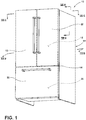
- a refrigerator 10 having a front surface 14 that is generally disposed around a front opening 16 ( FIG. 2 ) of a refrigerator cabinet 12 ( FIG. 2 ).
- the refrigerator cabinet 12 is contemplated to be an insulated space for storing fresh food items having first and second doors 18, 20 that are rotatably coupled to the front surface 14 of the refrigerator cabinet 12 for selectively providing access to the refrigerator cabinet 12.
- a freezer drawer 22 is configured to selectively provide access to a freezer cabinet 24 ( FIG. 2 ) disposed below the refrigerator cabinet 12.
- the refrigerator 10 shown in FIG. 1 is an exemplary embodiment of a refrigerator for use with the present concept, and is not meant to limit the scope of the present concept in any manner.
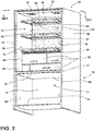
- the refrigerator 10 is shown with the first and second doors 18, 20 and freezer drawer 22 removed to reveal the refrigerator cabinet 12 and freezer cabinet 24 which are separated by a mullion 26.
- a number of shelves 28 are shown disposed in the refrigerator cabinet 12 and are contemplated to be vertically adjustable therein.
- the refrigerator cabinet 12 also includes a number of drawers 30 for storing various items, such as fresh fruits and vegetables, in specific temperature controlled environments.
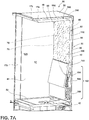
- the refrigerator 10 includes an exterior wrapper 32 which includes first and second side walls 34, 36, top wall 38 and rear wall 40 ( FIG. 7A ).
- the exterior wrapper 32 is contemplated to be a metal component formed of a sheet metal material.
- the refrigerator 10 further includes a refrigerator liner 42 which includes first and second side walls 44, 46, top wall 48, rear wall 50 ( FIG. 7A ) and bottom wall 52.
- the freezer cabinet 24 also includes a freezer liner 54 having first and second side walls 56, 58 and top wall 60.
- the refrigerator liner 42 and freezer liner 54 are also contemplated to be metal components made of a sheet metal material that is bent and welded to the specifications of the refrigerator 10. As encapsulated by the exterior wrapper 32, the refrigerator liner 42 and freezer liner 54 are spaced-apart from the exterior wrapper 32 to provide an insulating space therebetween, as further described below.
- a wall covering assembly 62 includes a rear wall 64 and a top wall 66 disposed over and adjacent to the rear wall 50 ( FIG. 7A ) and top wall 48 of the refrigerator liner 42. In this way, the wall covering assembly 62 defines rearmost and uppermost parameters of the refrigerator cabinet 12 at rear wall 64 and top wall 66.
- the wall covering assembly 62 is configured to conceal cooling components of the refrigerator 10, and also conceal air distribution systems for the cooling of the refrigerator cabinet 12 and for specifically directing air flow for an air curtain system as further described below.
- the rear wall 64 of the wall covering assembly 62 is a ventilated wall having a plurality of ports 132 disposed therethrough.
- the rear wall 64 of the wall covering assembly 62 is configured to provide cooled air to the refrigerator cabinet 12 in use, as further described below.
- the duct assembly 70 is configured to be concealed by the wall covering assembly 62 as best shown in FIG. 6 .
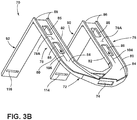
- the duct assembly 70 includes a lower portion 72 having a lower opening 74 ( FIG. 3B ) disposed therethrough.
- the lower opening 74 is configured to align with a housing for a radial fan for providing air to the duct assembly 70 as powered by the radial fan ( FIG. 6 ).
- first and second upright ducts 76, 78 define an upright portion of the duct assembly 70.
- the first and second upright ducts 76, 78 each include first and second side walls 80, 82, which are spaced-apart and interconnected by front walls 84 as best shown in FIG. 3B .
- the first and second side walls 80, 82 and front wall 84 of the first and second upright ducts 76, 78 form vertical channels 76A, 78A which open outwardly towards the rear wall 50 of the refrigerator liner 42 in assembly.
- the first and second side walls 80, 82 include outermost contact surfaces 86 which are configured to contact the rear wall 50 of the refrigerator liner 42 to substantially close off the channels 76A, 78A for channeling air upwards along the first and second upright ducts 76, 78 as powered by the radial fan.
- first and second upper ducts 90, 92 outwardly extend in a substantially horizontal manner to define a lateral portion of the duct assembly 70.
- the upper ducts 90, 92 each include first and second side walls 94, 96 which are interconnected by bottom walls 98 to form upwardly opening horizontal channels 90A, 92A, respectively.
- channels 90A, 92A, channels 90A, 92A are fluidly connected with channels 76A, 78A, respectively.
- air flow is configured to flow upward in a direction as indicated by arrows 104, 106 in vertical channels 76A, 78A, respectively, and is then directed outwardly in the directions as indicated by arrows 108, 110 along channels 90A, 92A, respectively.
- the air flows along the channels 90A, 92A towards an end wall 112 thereof, the air is directed downward through downwardly opening vents 114, 116 in the direction as indicated by arrows 118, 120 ( FIG. 3A ).
- Channels 90A, 92A are upwardly opening channels defined by first and second side walls 94, 96 which include uppermost contact surfaces 122 which are configured to be engaged with the top wall 48 of the refrigerator liner 42 ( FIG. 2 ), or other like structure, for closing off the upwardly opening channels 90A, 92A.
- the channels 90A, 92A are configured to direct air flow to the downwardly opening vents 114, 116 for providing an air curtain within the refrigerator cabinet 12 which can create an air barrier for blocking direct air flow to the gaskets of the refrigerator 10, and for keeping cold air inside the refrigerator cabinet 12, as further described below.
- the outwardly opening vertical channels 76A, 78A of the duct assembly 70 are shown with the outwardly extending upper ducts 90, 92 extending in a substantially perpendicular manner relative to the first and second lower ducts 76, 78.
- the configuration of the duct assembly 70 is configured to compliment the configuration of the wall covering assembly 62, as shown in FIG. 5 , and the refrigerator liner, as shown in FIG. 7A .
- the first and second upright ducts 76, 78 include a plurality of access apertures 85 disposed through the front wall 84 thereof.
- the access apertures 85 are configured to allow for air to pass through the upright ducts 76, 78 as air is directed in the travel pass as indicated by arrows 104 and 106. In this way, the upwardly directed air can escape through the access apertures 85 to provide cooling air to the refrigerator cabinet 12 through the ventilated rear wall 64 of the wall covering assembly 62, as further described below.
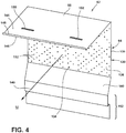
- the wall covering assembly 62 is shown having rear wall 64 and top wall 66, wherein the rear wall 64 is substantially vertical with top wall 66 extending outwardly therefrom in a substantially perpendicular or horizontal manner.
- the rear wall 64 includes a ventilated portion 130 which is a substantially planar portion having a plurality of ports 132 disposed therethrough.
- the ports 132 define venting apertures dispersed across the ventilated portion 130, such that the entire ventilated portion 130 includes a designed pattern 134 made up of the ports 132 disposed therethrough.
- the ventilated portion 130 includes an outer surface 136 and an inner surface 138.
- the top wall 66 of the wall covering assembly 62 includes an inner surface 144 and an outer surface 146.
- a front lip portion 148 is disposed at a front edge of the top wall 66 as shown in FIG. 4 .
- the top wall 66 further includes venting slots 150, 152 which are configured to align with the downwardly opening vents 114, 116 of the duct assembly 70 shown in FIGS. 3A and 3B . In this way, air channeled through the duct assembly 70 is directed downwardly through the downwardly opening vents 114, 116, in the direction indicated by arrows 118, 120 in FIG. 3A for dispersement into the refrigerator cabinet 12 through venting slots 150, 152 of the wall covering assembly 62.
- the ports 132 open outwardly into the refrigerator cabinet for cooling the refrigerator cabinet 12 with an air flow directed in a perpendicular manner emanating from the ventilated portion 130 of the wall covering assembly 62 as indicated by arrow 140.
- an air curtain (AC FIG. 5 ) will be created by the air directed downwardly through venting slots 150, 152 which will help prevent the air exiting the ports 132, indicated by arrow 140, from directly contacting the doors 18, 20 ( FIG. 1 ) of the refrigerator 10, and also from directly contacting gaskets disposed around the doors 18, 20, as further described below.
- Refrigerated air directly contacting the gaskets of the refrigerator 10 may cause condensation on outer surfaces of the gaskets, which are exposed to the ambient air of the room in which the refrigerator 10 is disposed.
- This condensation is an undesired effect of cooling the refrigerator cabinet 12, such that the present concept provides an air curtain (AC FIG. 5 ) for preventing outwardly directed cooled air along path 140 emanating from the ventilated portion of the wall covering assembly 62 from reaching the gaskets without disruption.
- AC FIG. 5 an air curtain for preventing outwardly directed cooled air along path 140 emanating from the ventilated portion of the wall covering assembly 62 from reaching the gaskets without disruption.
- the wall covering assembly 62 also includes an inclined portion 160 which generally defines a housing area 162 which is used to house and conceal components used to cool air for cooling the refrigerator cabinet 12. Such components may include fans for directing the cooled air, evaporators, condensers and other components (i.e., electrical components) of the refrigerator 10. As better shown in FIGS. 6 and 7 , the wall covering assembly 62 provides a false wall to the refrigerator cabinet 12 that is spaced-apart from the refrigerator liner 42, such that the duct assembly 70 and other components of the refrigerator 10 can also be concealed behind the false wall of wall covering assembly 62.
- the duct assembly 70 is shown in phantom as mounted on the wall covering assembly 62 at inner surfaces 144, 138 of the wall covering assembly 62.
- the upper ducts 90, 92 are shown disposed on the inner surface 144 of the top wall 66 of the wall covering assembly 62.
- First and second upright ducts 76, 78 are shown disposed on the rear inner surface 138 of the rear wall 64 of the wall covering assembly 62 at ventilated portion 130.
- a number of the ports 132A of ports 132 are aligned with the access apertures 85 of the first and second upright ducts 76, 78 which will provide air flow in an outward direction as indicated by arrow 140.
- An air curtain AC is defined by the downwardly directed air flowing from venting slots 150, 152 as channeled to the venting slots 150, 152 of the wall covering assembly 62 by first and second upper ducts 90, 92.
- the air curtain AC shown in FIG. 5 is substantially defined by the downward air flow indicated by arrows 118, 120 shown in FIG. 3A of the duct assembly 70. As shown in FIG.
- the air curtain AC intersects and disrupts the outward air flow 140 from ports 132A, such that the outward flow of air in the direction as indicated by arrow 140 will not directly contact the front portion of the refrigerator cabinet 12, but will instead be disrupted by the air curtain AC. In this way, a condensation effect on a gasket for the refrigerator 10 can be avoided, as further described below.
- a fan housing 164 is shown disposed at the lower portion 72 of the duct assembly 70 which is configured to house a radial fan for propelling air along the duct assembly 70 as indicated by arrows 104, 106, 108 and 110 and further downward in the direction as indicated by arrows 118, 120 ( FIG. 3A ) to create the air curtain AC.
- the fan housing 164 is disposed in the housing area 162 defined by the wall covering assembly 62 at inclined portion 160, as better shown in FIGS. 6 and 7A .
- the refrigerator 10 is shown with the exterior wrapper 32 and liner 42 removed to reveal the duct assembly 70 disposed on the wall covering assembly 62.
- the duct assembly 70 is configured to create an air curtain AC along a front portion 12A of the refrigerator cabinet 12.
- the front portion 12A of the refrigerator cabinet 12 is shown disposed adjacent to the second door 20 of the refrigerator 10 and is contemplated to provide air flow in a downward direction between the first and second doors 18, 20 and the outermost portions of the shelves 28 and drawers 30.
- the air curtain AC will intercept or otherwise disrupt the flow of air from the ports 132A of the ventilated portion 130 of the wall covering assembly 62 shown outwardly directed into the refrigerator cabinet 12 in the direction as indicated by arrow 140.
- a trim breaker 170 includes a stepped configuration having an outer rim 172 and an inner rim 174.
- the trim breaker 170 is configured to couple the exterior wrapper 32 ( FIG. 2 ) to the liner 42 ( FIG. 2 ). Specifically, the exterior wrapper 32 will couple to the outer rim 172 of the trim breaker 170, and the liner 42 will couple to the inner rim 174 of the trim breaker 170.
- a gasket 180 is positioned between the trim breaker 170 and the doors 18, 20, .
- the gasket 180 is contemplated to be coupled to the door and configured to form a seal against the front surface 14 ( FIGS. 1 and 2 ) of the refrigerator 10 and the doors 18, 20.
- the gasket 180 forms a seal against the front surface 14 of the refrigerator 10 when the first and second doors 18, 20 are in the closed position as shown in FIG. 1 .
- the air curtain AC of the present concept is provided to prevent cooled air, distributed through the ventilated portion 130 of the wall covering assembly 62, from directly contacting the gasket assembly 180.
- the gasket assembly 180 is contemplated to be a polymeric part that is in contact with the room environment outside of the refrigerator 10, as well as the cooled compartment of the refrigerator compartment 12. Air flow in the direction as indicated by arrow 140 may cause condensation to form on the outer surfaces of the gasket assembly 180 if this air flow is not disrupted by the air curtain AC of the present concept.
- the duct assembly 70 includes the upper lateral ducts 90, 92 which extend across the top wall 66 of the wall covering assembly 62 to properly position the air curtain AC at the front portion 12A of the refrigerator cabinet 12 for disrupting direct contact between the cooled air distributed through the ventilated portion 130 of the wall covering assembly 62 in the direction as indicated by arrow 140, and the gasket assembly 180.
- the gasket assembly 180 may include a number of separate gaskets used to seal the doors 18, 20 individually.
- a fan 166 is shown positioned within the fan housing 164 for providing cooled air to the duct assembly 70.
- the fan 166 is a radial fan disposed above an evaporator 168.
- the evaporator 168 is configured to provide cooled air to the housing area 162 defined between the wall covering assembly 62 and the liner 42 for dissemination of the cooled air into the refrigerator cabinet 12 via the ports 132A disposed on the ventilated portion 130 of the wall covering assembly 62.
- the fan 166 is configured to draw cooled air provided by the evaporator 168 into the duct assembly 70 for moving the cooled air in a downward direction at the air curtain AC along the front portion 12A of the refrigerator cabinet 12.
- the cooled air is not only provided by the ventilated portion 130 of the wall covering assembly 62, but is also provided by the downward air flow of the air curtain AC into the refrigerator cabinet 12.
- the fan assembly 166 is in thermal communication with the evaporator 168 and is fluidly connected to the duct assembly 70 within the housing area 162.
- the fan assembly 166 is configured to move cooled air from the evaporator 168 to the duct assembly 70 and propel the air through the upright ducts 76, 78 and upper ducts 90, 92.
- the evaporator 168 and fan assembly 166 are substantially concealed by the wall covering assembly 62 within the refrigerator cabinet 12 in assembly.
- the air curtain AC directs air flow along the front portion 12A of the refrigerator cabinet 12 which is positioned along inner surfaces of the doors 18, 20 and distal ends of the shelves 28 and drawers 30. It is further contemplated that the air curtain AC may be provided for accelerated air flow when the doors 18, 20 are opened in order to retain cooled air within the refrigerator cabinet 12 while a user keeps one or both of the doors 18, 20 in an open position. As further noted in FIG. 6 , the evaporator 168 and fan 166 are disposed within the housing area 162 created by the wall covering assembly 62.
- the wall covering assembly 62 creates a false wall disposed at both the rear portion and upper portion of the refrigerator cabinet 12 to conceal the fan 166 and evaporator 168, as well as the duct assembly 70, and other like components used to cool the refrigerator cabinet 12.
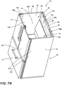
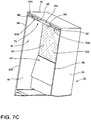
- channels 76A, 78A, 90A, 92A are outwardly opening channels which are closed off in assembly by the rear wall 50 of the refrigerator liner 42, as shown in FIG. 7B , and further closed off by top wall 48 of the refrigerator liner 42, as shown in FIG. 7C .
- the refrigerator 10 is shown with the exterior wrapper 32 disposed around the refrigerator liner 42 to create a spacing 200 therebetween, which may be a vacuum insulated space.
- the refrigerator liner 42 includes a rear wall 50 that is adjacent to and spaced-apart from the rear wall 64 of the wall covering assembly 62.
- the top wall 48 of the refrigerator liner 42 is disposed adjacent to and spaced-apart from the top wall 66 of the wall covering assembly 62.
- a cavity 190 is formed between the spaced-apart portions of the refrigerator liner 42 and the wall covering assembly 62.
- the cavity 190 includes a first portion 192 that extends between the rear wall 64 of the wall covering assembly 62 and the rear wall 50 of the refrigerator liner 42. As shown in FIG. 7A , the first portion 192 of the cavity 190 houses the vertical section of the duct assembly 70, which is indicated as upright duct 76 in FIG. 7A .
- the cavity 190 further includes a second portion 194 that extends outwardly in a substantially horizontal manner relative to the first portion 192.
- the second portion 194 is configured to house the upper or lateral ducts 90, 92 ( FIG. 6 ) of the duct assembly 70, such that the duct assembly 70 can direct air for the air curtain to the front portion 12A of the refrigerator cabinet 12 in a concealed manner within the second portion 194 of the cavity 190.
- the inner and outer rim portions 172, 174 of the trim breaker 170 are shown coupled to the exterior wrapper 32 and the liner 42, respectively.
- the cross-sectional view of the refrigerator 10 shows the first portion 192 of the cavity 190 having the first and second upright ducts 76, 78 disposed therein with channels 76A, 78A, respectively.
- the rear wall 50 of the refrigerator liner 42 is shown as well as rear wall 40 of the exterior wrapper 32.
- a spacing 200 exists between the exterior wrapper 32 and the refrigerator liner 42 which may be a vacuum insulated space for insulating the refrigerator cabinet 12.
- the gasket 180 is shown on both doors 18, 20 relative to the trim breaker 170. As shown in FIG.
- channels 76A, 78A are closed by the rear wall 50 of the refrigerator liner 42 to properly channel air upward in the duct assembly 70.
- air will also be directed outwardly into the refrigerator cabinet 12 through ports 132A that align with access apertures 85 of the channel 76A, 78A, as best shown in FIG. 6 .
- the second portion 194 of the cavity 190 is shown housing the upper lateral ducts 90, 92 having channels 90A, 92A, respectively.
- the upwardly or outwardly opening channels 90A, 92A are shown closed off by a top wall 48 of the refrigerator liner 42 for properly channeling air towards the downwardly opening venting slots 150, 152 for providing the air curtain AC as shown in FIG. 5 .
- the duct assembly 70 is shown having upright duct 76 fluidly connected to upper duct 90 for providing air to downwardly opening vent 114 which is shown aligned with venting slot 150 disposed in the wall covering assembly 62. Air flow in the direction as indicated by arrow 140 is provided through ports 132A, which align with access aperture 85 in upright duct 76.
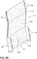
- FIG. 8A another embodiment of a wall covering assembly 210 is shown having a rear wall 212. It is contemplated that the wall covering assembly 210 will also include a top wall similar to top wall 66 shown and described above with wall covering assembly 62.
- the rear wall 212 of wall covering assembly 210 includes an upper portion 212A, a middle portion 212B and a bottom portion 212C.
- the middle portion 212B is an inclined portion which creates a housing area 214 disposed behind the rear wall 212 for housing components for cooling a refrigerator.
- the rear wall 212 includes a plurality of ports 216 disposed in a pattern 218 along the upper, middle and bottom portions 212A, 212B, 212C of the rear wall 212.
- the rear wall 212 includes a pattern 218 of ports 216 substantially covering the entirety of the rear wall 212.
- the ports 216 are contemplated to be optimally sized to sufficiently provide air in an outward direction as indicated by arrow 220 into a refrigerator cabinet, such as refrigerator cabinet 12 described above. It is contemplated that a number of the ports 216 will be aesthetic only, while other ports 216A may be aligned with access apertures disposed in a duct assembly, such as access apertures 85 shown in duct assembly 70 and described above.
- the rear wall 212 of the wall covering assembly 210 includes a ventilated portion 222 which includes a pattern 218 of ports 216 disposed substantially throughout the entirety of the rear wall 212.
- ports 216A While only ports 216A provide air flow in the direction as indicated by arrow 220 into the refrigerator cabinet, the remaining ports 216 provide the overall patterned appearance for the rear wall 212 of the wall covering assembly 210.
- the ports 216 may include round, square, or other like shaped apertures for adequately providing air flow into a refrigerator cabinet. Further, combination of variously shaped apertures may be used for the ports 216 and 216A for providing a variety of patterns 218 on the rear wall 212 of wall covering assembly 210.
- the ports 216 and 216A function in a similar manner as the ports 132, 132A described above with wall covering assembly 62.
- the rear wall 212 is a fully ventilated rear wall 212, whereas the rear wall 64 of wall covering assembly 62 included only a ventilated portion 130.
- FIG. 8B a rearview of the wall covering assembly 210 is shown with attachment features 224 disposed thereon for coupling the rear wall 212 to the inside of a refrigerator cabinet.
- the housing area 214 may include a radial fan that directly provides air flow into a refrigerator cabinet at ports 216B. Such a cooling configuration may provide a quick chill feature to the refrigerator cabinet and access through ports 216B may be selectively provided when desired by a user.
- the wall covering assembly 210 is shown disposed within the refrigerator cabinet 12.
- the wall covering assembly 210 includes a top wall 226 which is similar to top wall 66 shown and described above.
- the radial fan 166 is disposed within the radial fan housing 164 adjacent an evaporator 168 for providing cooling into the refrigerator cabinet 12.
- the top wall 226 and the rear wall 212 of the wall covering assembly 210 are disposed adjacent to the top wall 48 and rear wall 50 of the refrigerator liner 42 such that a spacing 190 is created therebetween for housing a duct assembly, such as duct assembly 70 shown and described above.
- ports 216B are disposed on the inclined portion or middle portion 212B of rear wall 212 for directly providing air into the refrigerator cabinet 12 as propelled by the radial fan 166.
- FIG. 10 another embodiment of a wall covering assembly 230 is shown having a rear wall 232 and a top wall 234.
- the wall covering assembly 230 is contemplated to be received in a refrigerator liner 42 in a manner similar to wall covering assembly 62 discussed above.
- the wall covering assembly 230 defines rearmost and uppermost parameters of the refrigerator cabinet 12 at rear wall 232 and top wall 234.
- the wall covering assembly 230 is used to conceal an air distribution system 231 in a manner similar to wall covering assembly 62 discussed above.
- the rear wall 232 is substantially vertical as disposed within refrigerator liner 42, and top wall 234 extends outwardly from the rear wall 232 in a substantially perpendicular manner. As shown in FIG.
- the rear wall 232 includes a ventilated portion 236 which is a substantially planar portion having a plurality of ports 238 disposed therethrough.
- the ports 238 define venting apertures dispersed across the ventilated portion 236, such that the entire ventilated portion 236 includes a designed pattern 240 made up of the ports 238 disposed therethrough.
- the pattern 240 of ports 238 extends across the entirety of the ventilated portion 236 between the sidewalls 44 and 46 of the refrigerator liner 42.
- the pattern 240 of ports 238 includes a first set of ports 238A that are in communication with the air distribution system 231.
- the pattern 240 of ports 238 further includes a second set of ports 238B that are in communication with a cavity similar to cavity 190 formed between the spaced-apart portions of the refrigerator liner 42 and the wall covering assembly 230, as discussed above.
- ports 238A introduce cooled air into the refrigerator cabinet 12, while ports 238B will help provide for a complete pattern 240 extending across the entire ventilated portion 236 of rear wall 232.
- the entirety of the rear wall 232 can be a ventilated portion, such as depicted on rear wall 212 of FIG. 8A discussed above.
- the top wall 234 of the wall covering assembly 230 includes a front lip portion 242 disposed at a forward most edge 244 of the top wall 234.
- the front lip portion 242 is an upwardly angled portion connecting the forward most edge 244 of the top wall 234 with the top wall 48 of the refrigerator liner 42.
- On the front lip portion 242, a number of angled venting slots 246A and 246B are disposed which are in communication with the air distribution system 231. Specifically, the angled venting slots 246A and 246B are in communication with a lateral portion of the air distribution system 231 as best described below with reference to FIG. 13 .
- the angled venting slots 246A and 246B are angled outward and downward in a direction as indicated by arrow 248. With the location of the angled venting slots 246A and 246B on the top wall 234 of wall covering assembly 230, the angled venting slots 246A and 246B are positioned at an upper portion of the refrigerator cabinet 12. This location provides the angled venting slots 246A and 246B with access to storage bins and shelves disposed on upper inner surfaces of the doors 18 and 20 ( FIG. 1 ) to cool these compartments without disruption from the air curtain, as best shown in FIG. 14 .
- the top wall 234 includes venting slots 250, 252 which are configured to align with downwardly opening vents of a duct assembly of the air distribution system 231, as best shown in FIG. 13 .
- venting slots 250, 252 are configured to align with downwardly opening vents of a duct assembly of the air distribution system 231, as best shown in FIG. 13 .
- an air curtain is formed through venting slots 250, 252 in a manner similar to air curtain AC shown and described above with reference to FIG. 5 emanating from venting slots 150, 152.
- the wall covering assembly 230 provides an air curtain from venting slots 250, 252, such that air exiting the ports 238A will be disrupted from directly contacting the inner surfaces of the doors 18, 20 ( FIG.
- the wall covering assembly 230 also includes an inwardly inclined portion 254 and a base portion 256 which generally define a housing area 258 which is used to house and conceal components used to cool air for cooling the refrigerator cabinet 12.
- Such components may include fans for directing the cooled air, evaporators, condensers and other components (i.e., electrical components) of the refrigerator 10.
- FIG. 11 rear wall 232 is shown exploded away from the refrigerator cabinet 12 to reveal a duct assembly 70A shown disposed on the rear wall 50 of the refrigerator liner 42.
- the duct assembly 70A is akin to duct assembly 70 shown and described above, such that like reference numerals are used herein to describe similar features of duct assembly 70A.
- duct assembly 70A is part of the air distribution system 231 configured to be concealed by the wall covering assembly 230, as best shown in FIG. 10 .
- the duct assembly 70A includes a lower portion 72 having a lower opening 74 ( FIG. 12 ) disposed therethrough.
- first and second upright ducts 76, 78 define an upright portion of the duct assembly 70A.
- the front walls 84 of the first and second upright ducts 76, 78 include access apertures 260 which are disposed in a complimentary pattern relative to pattern 240 of the ports 238 disposed on rear wall 232.
- the access apertures 260 are configured to align with the associated ports 238A disposed through the ventilated portion 236 of rear wall 232 to provide cooled air to the refrigerator compartment 12 through the wall covering assembly 230.
- the top wall 234 of the wall covering assembly 230 is shown exploded away from the refrigerator cabinet 12 to reveal first and second upper ducts 90, 92 of the duct assembly 70A shown disposed on the top wall 48 of the refrigerator liner 42.
- the first and second upper ducts 90, 92 outwardly extend in a substantially horizontal manner relative to the first and second upright ducts 76, 78 to define a lateral portion of the duct assembly 70A.
- Air is powered by the fan of the air distribution system 231 ( FIG. 10 ) and is directed from the first and second upright ducts 76, 78 to the first and second upper ducts 90, 92.
- the venting slots 250, 252 of the top wall 234 of the wall covering assembly 230 align with the downwardly opening vents 114, 116 disposed on the first and second upper ducts 90, 92, respectively.
- the first and second upper ducts 90, 92 include end walls 112 having the venting apertures 262A and 262B disposed thereon. End walls 112 are contemplated to be disposed at a complementary angle relative to the front lip portion 242 of top wall 234.
- venting apertures 262A and 262B of the first and second upper ducts 90, 92 align with the angled venting slots 246A and 246B disposed on front lip portion 242 of the top wall 234 of the wall covering assembly 230 to provide cooled air from the duct assembly 70A to the storage compartments or bins disposed on the inner surfaces of the doors 18, 20, as shown in FIG. 14 .
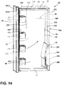
- FIG. 14 a cross-sectional view of the refrigerator compartment 12 of FIG. 10 is shown.
- the air distribution within the refrigerator compartment 12 is depicted. Specifically, cooled air emanating from the rear wall 232 of the wall covering assembly 230 is introduced into the refrigerator compartment 12 along a substantially horizontal path as indicated by arrow 270. This air is introduced through the first set of ports 238A of the rear wall 232 shown in FIG. 10 . As the cooled air flowing along the path as indicated by arrow 270 approaches the doors 18, 20 of the refrigerator 10, the cooled air is disrupted by the downwardly directed air curtain introduced into the refrigerator compartment 12 at venting slots 250, 252 of the top wall 234 along a path as indicated by arrow 272.
- door 18 includes an inner surface 176 having a plurality of storage bins 178 disposed thereon.
- the storage bins 178 are contemplated to be adjustable members that couple to the inner surface 176 of the door 18. Cooled air is directed towards the storage bins 178 along the path as indicated by arrow 274 for cooling the contents of the bins 178 in use.
- the air directed along the path indicated by arrow 274 emanates from the angled venting slots 246A and 246B disposed on front lip portion 242 of the top wall 234 of the wall covering assembly 230.
- the air flow at arrow 274 that is used to cool the contents of the storage bins 178 is uninterrupted by the downwardly directed air curtain depicted at arrow 272. It is further contemplated that the angled venting slots 246A and 246B disposed on front lip portion 242 of the top wall 234 of the wall covering assembly 230 are finely tuned to concentrate airflow on the storage bins 178 of the inner surface 176 of the door 18, and therefore do not direct air towards the gasket assembly 180 of the door 18.
- the wall covering assembly 230 is shown having the ventilated portion 236 with a plurality of ports 238 disposed therethrough.
- the ports 238 are shown in a pattern 240A which includes a first group of ports 238A which are disposed adjacent to the first and second upright ducts 76, 78, such that ports 238A are in communication with the air distribution system 231 to introduce cooled air into the refrigerator compartment 12 in a substantially horizontal manner.
- the ports 238A shown in FIG. 15A are contemplated to be round ports having a diameter of approximately 10 mm.
- the second set of ports 238B may include round ports having a diameter of approximately 7 mm.
- the ports 238A generally follow the contours of the first and second upright ducts 76, 78 as shown in the phantom lines provided in FIG. 15A .
- the ports 238 of the embodiment shown in FIG. 15A are arranged in a pattern 240A that covers the entirety of ventilated portion 236 of rear wall 232 between opposite ends OE1 and OE2 thereof.
- the pattern 240A includes a first set of ports 238A that are in communication with the air distribution system 231 along the first and second upright ducts 76, 78, and a second set of ports 238B which open into the refrigerator cabinet 12 on one side of the rear wall 232, and open into a cavity 190 ( FIG. 7B ) defined between the rear wall 232 of the wall covering assembly 230 and the rear wall 50 of the refrigerator liner 42 on an opposite side of the rear wall 232.
- the ports 238 are shown in a pattern 240B which includes a first group of ports 238A which are disposed adjacent to the first and second upright ducts 76, 78, such that ports 238A are in communication with the air distribution system 231 to introduce cooled air into the refrigerator compartment 12 in a substantially horizontal manner.
- the ports 238A shown in FIG. 15B are contemplated to be round ports having a diameter of approximately 13 mm.
- the second set of ports 238B may include round ports having a diameter of approximately 8 mm. While the embodiments shown in FIGS.
- 15A and 15B include mainly round ports 238, it is contemplated that other port shapes can be used having other dimensions to provide an aesthetically pleasing pattern covering, or partially covering, the ventilated portion 236 of the rear wall 232.
- the ports 238A generally follow the contours of the first and second upright ducts 76, 78 as shown in the phantom lines provided in FIG. 15B .
- the pattern 240B of ports 238 cover the entirety of ventilated portion 236 of rear wall 232 between opposite ends OE1 and OE2 thereof, however, it is contemplated that pattern 240B may cover only a portion of the ventilated portion 236 to achieve a desired aesthetic for the pattern 240B.
- the pattern 240B includes a first set of ports 238A that are in communication with the air distribution system 231 along the first and second upright ducts 76, 78, and a second set of ports 238B which open into the refrigerator cabinet 12 on one side of the rear wall 232, and open into a cavity 190 ( FIG. 14 ) defined between the rear wall 232 of the wall covering assembly 230 and the rear wall 50 of the refrigerator liner 42 on an opposite side of the rear wall 232.
- the term "coupled” in all of its forms, couple, coupling, coupled, etc. generally means the joining of two components (electrical or mechanical) directly or indirectly to one another. Such joining may be stationary in nature or movable in nature. Such joining may be achieved with the two components (electrical or mechanical) and any additional intermediate members being integrally formed as a single unitary body with one another or with the two components. Such joining may be permanent in nature or may be removable or releasable in nature unless otherwise stated.
- elements shown as integrally formed may be constructed of multiple parts or elements shown as multiple parts may be integrally formed, the operation of the interfaces may be reversed or otherwise varied, the length or width of the structures and/or members or connector or other elements of the system may be varied, the nature or number of adjustment positions provided between the elements may be varied.
- the elements and/or assemblies of the system may be constructed from any of a wide variety of materials that provide sufficient strength or durability, in any of a wide variety of colors, textures, and combinations. Accordingly, all such modifications are intended to be included within the scope of the present invention.
Landscapes
- Engineering & Computer Science (AREA)
- Chemical & Material Sciences (AREA)
- Combustion & Propulsion (AREA)
- Physics & Mathematics (AREA)
- Mechanical Engineering (AREA)
- Thermal Sciences (AREA)
- General Engineering & Computer Science (AREA)
- Cold Air Circulating Systems And Constructional Details In Refrigerators (AREA)
- Refrigerator Housings (AREA)
- Devices That Are Associated With Refrigeration Equipment (AREA)
Claims (15)
- Réfrigérateur (10), comprenant :une chemise (42) incluant une paroi supérieure (48), une paroi arrière (50), et des première et seconde parois latérales (44, 46) ;un ensemble revêtement de paroi (62) présentant une paroi supérieure (66) disposée adjacente à et espacée de la paroi supérieure (48) de la chemise (42) et une paroi arrière (64) disposée adjacente à et espacée de la paroi arrière (50) de la chemise (42) pour former une cavité (190) entre elles, dans lequel la paroi arrière (64) de l'ensemble revêtement de paroi (62) est en outre disposée entre les première et seconde parois latérales (44, 46) de la chemise (42) et inclut une partie ventilée (130), et en outre dans lequel la chemise (42) et l'ensemble revêtement de paroi (62) coopèrent pour définir une armoire de réfrigérateur (12) ; etun motif d'orifices (134) disposé sur la partie ventilée (130) de la paroi arrière (64) de l'ensemble revêtement de paroi (62), le motif d'orifices (134) incluant des premier et second ensembles d'orifices (132A, 132), dans lequel le second ensemble d'orifices (132) s'ouvre dans l'armoire de réfrigérateur (12) sur un premier côté de la paroi arrière (64) de l'ensemble revêtement de paroi (62) et s'ouvre en outre dans la cavité (190) sur un second côté de la paroi arrière (64) de l'ensemble revêtement de paroi (62), caractérisé par un ensemble de conduits (70) présentant une partie verticale (76, 78) disposée dans la cavité (190), dans lequel la partie verticale (76, 78) inclut une pluralité d'ouvertures d'accès (85), et dans lequel le premier ensemble d'orifices de ventilation (132A) est configuré pour s'aligner avec les ouvertures d'accès (85) de l'ensemble de conduits (70) pour introduire de l'air refroidi dans l'armoire de réfrigérateur (12) à travers la paroi arrière (64) de l'ensemble revêtement de paroi (62).
- Réfrigérateur (10) selon la revendication 1, dans lequel la partie ventilée (130) est disposée entre des extrémités opposées (OE1, OE2) de la paroi arrière (64) de l'ensemble revêtement de paroi (62).
- Réfrigérateur (10) selon la revendication 2, dans lequel les extrémités opposées (OE1, OE2) de la paroi arrière (64) de l'ensemble revêtement de paroi (62) viennent en butée contre les première et seconde parois latérales (44, 46) de la chemise (42).
- Réfrigérateur (10) selon l'une quelconque des revendications 2-3, dans lequel le motif d'orifices (134) recouvre sensiblement une totalité de la partie ventilée (130) entre les extrémités opposées (OE1, OE2) de la paroi arrière (64) de l'ensemble revêtement de paroi (62).
- Réfrigérateur (10) selon l'une quelconque des revendications 1-4, dans lequel la cavité (190) inclut une première partie (192) disposée entre la paroi arrière (50) de la chemise (42) et la paroi arrière (64) de l'ensemble revêtement de paroi (62), et en outre dans lequel la cavité (190) inclut une seconde partie (194) s'étendant vers l'extérieur à partir de la première partie (192), la seconde partie (194) de la cavité (190) disposée entre la paroi supérieure (48) de la chemise (42) et la paroi supérieure (66) de l'ensemble revêtement de paroi (62).
- Réfrigérateur (10) selon la revendication 5, dans lequel la partie verticale (76, 78) de l'ensemble de conduits (70) est positionnée à l'intérieur de la première partie (192) de la cavité (190).
- Réfrigérateur (10) selon la revendication 6, dans lequel l'ensemble de conduits (70) inclut en outre une partie latérale (90, 92) s'étendant vers l'extérieur à partir de la partie verticale (76, 78) de l'ensemble de conduits (70) et reliée de manière fluidique à celle-ci.
- Réfrigérateur (10) selon la revendication 7, dans lequel la partie latérale (90, 92) de l'ensemble de conduits (70) est positionnée à l'intérieur de la seconde partie (194) de la cavité (190).
- Réfrigérateur (10) selon l'une quelconque des revendications 7-8, dans lequel la partie latérale (90, 92) de l'ensemble de conduits (70) inclut un ou plusieurs évents s'ouvrant vers le bas (114, 116).
- Réfrigérateur (10) selon l'une quelconque des revendications 1-9, dans lequel la paroi supérieure (66) de l'ensemble revêtement de paroi (62) inclut une ou plusieurs fentes de ventilation (150, 152) disposées au-dessus d'une partie avant (12A) de l'armoire de réfrigérateur (12).
- Réfrigérateur (10) selon la revendication 10, dans lequel les un ou plusieurs évents s'ouvrant vers le bas (114, 116) de la partie latérale (90, 92) de l'ensemble de conduits (70) sont alignés avec les une ou plusieurs fentes de ventilation (150, 152) disposées à travers la paroi supérieure (66) de l'ensemble revêtement de paroi (62) et débouchent dans celles-ci.
- Réfrigérateur (10) selon la revendication 11, dans lequel l'ensemble de conduits (70) fournit un rideau d'air dirigé vers le bas (AC) au niveau de la partie avant (12A) de l'armoire de réfrigérateur (12) à travers les une ou plusieurs fentes de ventilation (150, 152) disposées à travers la paroi supérieure (66) de l'ensemble revêtement de paroi (62).
- Réfrigérateur (10) selon la revendication 12, dans lequel le premier ensemble d'orifices (132A) est configuré pour introduire un flux d'air refroidi dans l'armoire de réfrigérateur (12) d'une manière sensiblement horizontale, et en outre dans lequel le rideau d'air dirigé vers le bas (AC) interrompt le flux d'air refroidi provenant du premier ensemble d'orifices (132A) au niveau de la partie avant (12A) de l'armoire de réfrigérateur (12).
- Réfrigérateur (10) selon la revendication 7, dans lequel la partie latérale (90, 92) de l'ensemble de conduits (70) inclut des premier et second canaux (90A, 92A).
- Réfrigérateur (10) selon l'une quelconque des revendications 1-14, dans lequel la partie verticale (76, 78) de l'ensemble de conduits (70) inclut des premier et second canaux (76A, 78A).
Applications Claiming Priority (1)
| Application Number | Priority Date | Filing Date | Title |
|---|---|---|---|
| PCT/US2016/045995 WO2018030980A1 (fr) | 2016-08-08 | 2016-08-08 | Ensemble revêtement de paroi avec une structure de ventilation et système de rideau d'air |
Publications (3)
| Publication Number | Publication Date |
|---|---|
| EP3497389A1 EP3497389A1 (fr) | 2019-06-19 |
| EP3497389A4 EP3497389A4 (fr) | 2020-04-15 |
| EP3497389B1 true EP3497389B1 (fr) | 2021-05-26 |
Family
ID=61162342
Family Applications (1)
| Application Number | Title | Priority Date | Filing Date |
|---|---|---|---|
| EP16912813.9A Active EP3497389B1 (fr) | 2016-08-08 | 2016-08-08 | Ensemble revêtement de paroi avec une structure de ventilation et système de rideau d'air |
Country Status (3)
| Country | Link |
|---|---|
| US (3) | US11022364B2 (fr) |
| EP (1) | EP3497389B1 (fr) |
| WO (1) | WO2018030980A1 (fr) |
Families Citing this family (4)
| Publication number | Priority date | Publication date | Assignee | Title |
|---|---|---|---|---|
| US11079171B2 (en) * | 2016-10-26 | 2021-08-03 | Whirlpool Corporation | Refrigerator with surround illumination feature |
| EP4502515A3 (fr) * | 2017-12-18 | 2025-07-16 | Whirlpool Corporation | Appareil frigorifique doté d'un panneau mural comprenant une structure d'éclairage |
| CN110887305B (zh) * | 2019-12-02 | 2021-07-30 | 宁波韩电电器有限公司 | 一种三门风冷冰箱 |
| KR20220007293A (ko) * | 2020-07-10 | 2022-01-18 | 엘지전자 주식회사 | 냉장고 |
Family Cites Families (27)
| Publication number | Priority date | Publication date | Assignee | Title |
|---|---|---|---|---|
| US3455119A (en) * | 1968-02-16 | 1969-07-15 | Gen Motors Corp | Plural compartment high humidity domestic refrigerator |
| US3590596A (en) | 1969-06-06 | 1971-07-06 | Admiral Corp | Side-by-side refrigerator-freezer construction |
| US3678698A (en) | 1970-12-11 | 1972-07-25 | Gen Electric | Side-by-side refrigerator including low cost evaporator means |
| SU407161A1 (ru) | 1972-01-12 | 1973-11-21 | Е. А. Похиленко Государственный проектный институт Молдгипропищепром | Холодильная камера для хранения пищевых продуктов |
| US3893307A (en) | 1974-05-03 | 1975-07-08 | Gen Motors Corp | Refrigerator freezer with frost eliminator |
| US5347827A (en) | 1992-07-01 | 1994-09-20 | The Coca-Cola Company | Modular refrigeration apparatus |
| US5558419A (en) | 1995-01-30 | 1996-09-24 | Whirlpool Corporation | Pull-out freezer floor for refrigerator and freezers |
| AUPQ459699A0 (en) * | 1999-12-09 | 2000-01-13 | Orford Pty Ltd | Improved airflow arrangement for a refrigerator |
| TW522213B (en) * | 2000-07-21 | 2003-03-01 | Fujitsu General Ltd | Electric refrigerator |
| JP2002168560A (ja) | 2000-11-30 | 2002-06-14 | Sanyo Electric Co Ltd | 冷蔵庫 |
| US6550255B2 (en) | 2001-03-21 | 2003-04-22 | The Coca-Cola Company | Stirling refrigeration system with a thermosiphon heat exchanger |
| JP2002295948A (ja) | 2001-03-30 | 2002-10-09 | Fujitsu General Ltd | 電気冷蔵庫 |
| JP2002318055A (ja) * | 2001-04-20 | 2002-10-31 | Fujitsu General Ltd | 冷蔵庫 |
| FR2828079B1 (fr) | 2001-08-06 | 2003-10-17 | Bonnet Neve | Meuble frigorifique, notamment meuble vertical, du type a rideaux d'air froid a l'avant du meuble |
| US7254960B2 (en) | 2002-02-22 | 2007-08-14 | Multibras S.A. Eletrodomesticos | Air duct arrangement for a refrigerator |
| JP3857964B2 (ja) | 2002-07-31 | 2006-12-13 | 三洋電機株式会社 | 冷気通路制御装置 |
| WO2006032934A1 (fr) | 2004-09-20 | 2006-03-30 | Enervac-Flutec Ltd | Systeme de rideaux d’air pour refrigerateurs et vitrines frigorifiques commerciaux du type ouvert a l’avant |
| DE102008010520A1 (de) * | 2008-02-22 | 2009-09-03 | BSH Bosch und Siemens Hausgeräte GmbH | Kältegerät mit Umluftkühlung |
| JP2011064340A (ja) * | 2009-09-15 | 2011-03-31 | Sharp Corp | 冷蔵庫 |
| FR2980963B1 (fr) | 2011-10-07 | 2014-10-31 | Andre Renard | Amelioration aux appareils refrigeres d'exposition de produits |
| CN203704507U (zh) * | 2014-02-28 | 2014-07-09 | 海信(山东)冰箱有限公司 | 风冷冰箱 |
| BR102014012631A2 (pt) * | 2014-05-26 | 2015-12-22 | Whirlpool Sa | refrigerador provido de sistema de distribuição de ar |
| KR102326481B1 (ko) * | 2014-09-02 | 2021-11-16 | 삼성전자주식회사 | 냉장고 |
| US20160223244A1 (en) * | 2015-01-29 | 2016-08-04 | General Electric Company | Liner for a refrigerator appliance |
| JP6567918B2 (ja) * | 2015-08-07 | 2019-08-28 | 日立グローバルライフソリューションズ株式会社 | 冷蔵庫 |
| CN106247741A (zh) * | 2016-07-12 | 2016-12-21 | 青岛海尔股份有限公司 | 一种冰箱 |
| US10907889B2 (en) | 2016-08-08 | 2021-02-02 | Whirlpool Corporation | Wall covering assembly with ventilated portion and air curtain system |
-
2016
- 2016-08-08 EP EP16912813.9A patent/EP3497389B1/fr active Active
- 2016-08-08 US US16/309,178 patent/US11022364B2/en active Active
- 2016-08-08 WO PCT/US2016/045995 patent/WO2018030980A1/fr not_active Ceased
-
2021
- 2021-04-26 US US17/240,420 patent/US11674736B2/en active Active
-
2023
- 2023-04-27 US US18/308,209 patent/US12372293B2/en active Active
Also Published As
| Publication number | Publication date |
|---|---|
| EP3497389A4 (fr) | 2020-04-15 |
| US20210247125A1 (en) | 2021-08-12 |
| US20200309443A1 (en) | 2020-10-01 |
| US11674736B2 (en) | 2023-06-13 |
| US11022364B2 (en) | 2021-06-01 |
| US12372293B2 (en) | 2025-07-29 |
| US20230349623A1 (en) | 2023-11-02 |
| EP3497389A1 (fr) | 2019-06-19 |
| WO2018030980A1 (fr) | 2018-02-15 |
Similar Documents
| Publication | Publication Date | Title |
|---|---|---|
| US12372293B2 (en) | Wall covering assembly with ventilation pattern and air curtain system | |
| US10823481B2 (en) | Refrigerator compartment with evaporator to provide cold air to ice maker | |
| KR102749081B1 (ko) | 냉장고 | |
| US7726756B2 (en) | Refrigerator with varying width compartments and uniform width doors | |
| EP3056843B1 (fr) | Réfrigérateur | |
| US10907889B2 (en) | Wall covering assembly with ventilated portion and air curtain system | |
| JP4474276B2 (ja) | 冷蔵庫 | |
| EP4006457B1 (fr) | Réfrigérateur capable d'améliorer la circulation d'air dans une chambre de machine | |
| JP7161891B2 (ja) | 冷蔵庫 | |
| JP2022020773A (ja) | 冷蔵庫 | |
| CN212205234U (zh) | 一种冰箱 | |
| CN101893361B (zh) | 冰箱 | |
| KR100798941B1 (ko) | 냉장고용 야채박스 | |
| JP2023513226A (ja) | オープンディスプレイ冷蔵庫に対する改良 | |
| CN107917574B (zh) | 冰箱 | |
| JP2002147922A (ja) | 冷蔵庫 | |
| US12442589B2 (en) | Refrigerator appliance with airflow features | |
| JP2018105580A (ja) | 冷蔵庫 | |
| KR200148070Y1 (ko) | 오픈형 쇼케이스의 냉기통풍구조 | |
| JP2007089921A (ja) | システムキッチン | |
| CN117663593A (zh) | 一种冰箱 | |
| JPH11281247A (ja) | 冷蔵庫 | |
| MXPA97003109A (en) | Circulation structure of cooling air for refrigeration |
Legal Events
| Date | Code | Title | Description |
|---|---|---|---|
| STAA | Information on the status of an ep patent application or granted ep patent |
Free format text: STATUS: THE INTERNATIONAL PUBLICATION HAS BEEN MADE |
|
| PUAI | Public reference made under article 153(3) epc to a published international application that has entered the european phase |
Free format text: ORIGINAL CODE: 0009012 |
|
| STAA | Information on the status of an ep patent application or granted ep patent |
Free format text: STATUS: REQUEST FOR EXAMINATION WAS MADE |
|
| 17P | Request for examination filed |
Effective date: 20181031 |
|
| AK | Designated contracting states |
Kind code of ref document: A1 Designated state(s): AL AT BE BG CH CY CZ DE DK EE ES FI FR GB GR HR HU IE IS IT LI LT LU LV MC MK MT NL NO PL PT RO RS SE SI SK SM TR |
|
| AX | Request for extension of the european patent |
Extension state: BA ME |
|
| DAV | Request for validation of the european patent (deleted) | ||
| DAX | Request for extension of the european patent (deleted) | ||
| A4 | Supplementary search report drawn up and despatched |
Effective date: 20200318 |
|
| RIC1 | Information provided on ipc code assigned before grant |
Ipc: F25D 23/06 20060101ALI20200312BHEP Ipc: F25D 17/06 20060101AFI20200312BHEP |
|
| REG | Reference to a national code |
Ref country code: DE Ref legal event code: R079 Ref document number: 602016058648 Country of ref document: DE Free format text: PREVIOUS MAIN CLASS: F25D0023060000 Ipc: F25D0017060000 |
|
| GRAP | Despatch of communication of intention to grant a patent |
Free format text: ORIGINAL CODE: EPIDOSNIGR1 |
|
| STAA | Information on the status of an ep patent application or granted ep patent |
Free format text: STATUS: GRANT OF PATENT IS INTENDED |
|
| RIC1 | Information provided on ipc code assigned before grant |
Ipc: F25D 23/06 20060101ALI20210128BHEP Ipc: F25D 17/06 20060101AFI20210128BHEP |
|
| INTG | Intention to grant announced |
Effective date: 20210225 |
|
| GRAS | Grant fee paid |
Free format text: ORIGINAL CODE: EPIDOSNIGR3 |
|
| GRAA | (expected) grant |
Free format text: ORIGINAL CODE: 0009210 |
|
| STAA | Information on the status of an ep patent application or granted ep patent |
Free format text: STATUS: THE PATENT HAS BEEN GRANTED |
|
| AK | Designated contracting states |
Kind code of ref document: B1 Designated state(s): AL AT BE BG CH CY CZ DE DK EE ES FI FR GB GR HR HU IE IS IT LI LT LU LV MC MK MT NL NO PL PT RO RS SE SI SK SM TR |
|
| REG | Reference to a national code |
Ref country code: GB Ref legal event code: FG4D |
|
| REG | Reference to a national code |
Ref country code: CH Ref legal event code: EP |
|
| REG | Reference to a national code |
Ref country code: DE Ref legal event code: R096 Ref document number: 602016058648 Country of ref document: DE |
|
| REG | Reference to a national code |
Ref country code: AT Ref legal event code: REF Ref document number: 1396637 Country of ref document: AT Kind code of ref document: T Effective date: 20210615 |
|
| REG | Reference to a national code |
Ref country code: IE Ref legal event code: FG4D |
|
| REG | Reference to a national code |
Ref country code: LT Ref legal event code: MG9D |
|
| REG | Reference to a national code |
Ref country code: AT Ref legal event code: MK05 Ref document number: 1396637 Country of ref document: AT Kind code of ref document: T Effective date: 20210526 |
|
| PG25 | Lapsed in a contracting state [announced via postgrant information from national office to epo] |
Ref country code: HR Free format text: LAPSE BECAUSE OF FAILURE TO SUBMIT A TRANSLATION OF THE DESCRIPTION OR TO PAY THE FEE WITHIN THE PRESCRIBED TIME-LIMIT Effective date: 20210526 Ref country code: BG Free format text: LAPSE BECAUSE OF FAILURE TO SUBMIT A TRANSLATION OF THE DESCRIPTION OR TO PAY THE FEE WITHIN THE PRESCRIBED TIME-LIMIT Effective date: 20210826 Ref country code: AT Free format text: LAPSE BECAUSE OF FAILURE TO SUBMIT A TRANSLATION OF THE DESCRIPTION OR TO PAY THE FEE WITHIN THE PRESCRIBED TIME-LIMIT Effective date: 20210526 Ref country code: LT Free format text: LAPSE BECAUSE OF FAILURE TO SUBMIT A TRANSLATION OF THE DESCRIPTION OR TO PAY THE FEE WITHIN THE PRESCRIBED TIME-LIMIT Effective date: 20210526 Ref country code: FI Free format text: LAPSE BECAUSE OF FAILURE TO SUBMIT A TRANSLATION OF THE DESCRIPTION OR TO PAY THE FEE WITHIN THE PRESCRIBED TIME-LIMIT Effective date: 20210526 |
|
| REG | Reference to a national code |
Ref country code: NL Ref legal event code: MP Effective date: 20210526 |
|
| PG25 | Lapsed in a contracting state [announced via postgrant information from national office to epo] |
Ref country code: PT Free format text: LAPSE BECAUSE OF FAILURE TO SUBMIT A TRANSLATION OF THE DESCRIPTION OR TO PAY THE FEE WITHIN THE PRESCRIBED TIME-LIMIT Effective date: 20210927 Ref country code: NO Free format text: LAPSE BECAUSE OF FAILURE TO SUBMIT A TRANSLATION OF THE DESCRIPTION OR TO PAY THE FEE WITHIN THE PRESCRIBED TIME-LIMIT Effective date: 20210826 Ref country code: PL Free format text: LAPSE BECAUSE OF FAILURE TO SUBMIT A TRANSLATION OF THE DESCRIPTION OR TO PAY THE FEE WITHIN THE PRESCRIBED TIME-LIMIT Effective date: 20210526 Ref country code: SE Free format text: LAPSE BECAUSE OF FAILURE TO SUBMIT A TRANSLATION OF THE DESCRIPTION OR TO PAY THE FEE WITHIN THE PRESCRIBED TIME-LIMIT Effective date: 20210526 Ref country code: RS Free format text: LAPSE BECAUSE OF FAILURE TO SUBMIT A TRANSLATION OF THE DESCRIPTION OR TO PAY THE FEE WITHIN THE PRESCRIBED TIME-LIMIT Effective date: 20210526 Ref country code: LV Free format text: LAPSE BECAUSE OF FAILURE TO SUBMIT A TRANSLATION OF THE DESCRIPTION OR TO PAY THE FEE WITHIN THE PRESCRIBED TIME-LIMIT Effective date: 20210526 Ref country code: IS Free format text: LAPSE BECAUSE OF FAILURE TO SUBMIT A TRANSLATION OF THE DESCRIPTION OR TO PAY THE FEE WITHIN THE PRESCRIBED TIME-LIMIT Effective date: 20210926 Ref country code: GR Free format text: LAPSE BECAUSE OF FAILURE TO SUBMIT A TRANSLATION OF THE DESCRIPTION OR TO PAY THE FEE WITHIN THE PRESCRIBED TIME-LIMIT Effective date: 20210827 |
|
| PG25 | Lapsed in a contracting state [announced via postgrant information from national office to epo] |
Ref country code: NL Free format text: LAPSE BECAUSE OF FAILURE TO SUBMIT A TRANSLATION OF THE DESCRIPTION OR TO PAY THE FEE WITHIN THE PRESCRIBED TIME-LIMIT Effective date: 20210526 |
|
| PG25 | Lapsed in a contracting state [announced via postgrant information from national office to epo] |
Ref country code: EE Free format text: LAPSE BECAUSE OF FAILURE TO SUBMIT A TRANSLATION OF THE DESCRIPTION OR TO PAY THE FEE WITHIN THE PRESCRIBED TIME-LIMIT Effective date: 20210526 Ref country code: DK Free format text: LAPSE BECAUSE OF FAILURE TO SUBMIT A TRANSLATION OF THE DESCRIPTION OR TO PAY THE FEE WITHIN THE PRESCRIBED TIME-LIMIT Effective date: 20210526 Ref country code: CZ Free format text: LAPSE BECAUSE OF FAILURE TO SUBMIT A TRANSLATION OF THE DESCRIPTION OR TO PAY THE FEE WITHIN THE PRESCRIBED TIME-LIMIT Effective date: 20210526 Ref country code: ES Free format text: LAPSE BECAUSE OF FAILURE TO SUBMIT A TRANSLATION OF THE DESCRIPTION OR TO PAY THE FEE WITHIN THE PRESCRIBED TIME-LIMIT Effective date: 20210526 Ref country code: RO Free format text: LAPSE BECAUSE OF FAILURE TO SUBMIT A TRANSLATION OF THE DESCRIPTION OR TO PAY THE FEE WITHIN THE PRESCRIBED TIME-LIMIT Effective date: 20210526 Ref country code: SM Free format text: LAPSE BECAUSE OF FAILURE TO SUBMIT A TRANSLATION OF THE DESCRIPTION OR TO PAY THE FEE WITHIN THE PRESCRIBED TIME-LIMIT Effective date: 20210526 Ref country code: SK Free format text: LAPSE BECAUSE OF FAILURE TO SUBMIT A TRANSLATION OF THE DESCRIPTION OR TO PAY THE FEE WITHIN THE PRESCRIBED TIME-LIMIT Effective date: 20210526 |
|
| REG | Reference to a national code |
Ref country code: DE Ref legal event code: R097 Ref document number: 602016058648 Country of ref document: DE |
|
| REG | Reference to a national code |
Ref country code: CH Ref legal event code: PL |
|
| PLBE | No opposition filed within time limit |
Free format text: ORIGINAL CODE: 0009261 |
|
| STAA | Information on the status of an ep patent application or granted ep patent |
Free format text: STATUS: NO OPPOSITION FILED WITHIN TIME LIMIT |
|
| PG25 | Lapsed in a contracting state [announced via postgrant information from national office to epo] |
Ref country code: MC Free format text: LAPSE BECAUSE OF FAILURE TO SUBMIT A TRANSLATION OF THE DESCRIPTION OR TO PAY THE FEE WITHIN THE PRESCRIBED TIME-LIMIT Effective date: 20210526 |
|
| REG | Reference to a national code |
Ref country code: BE Ref legal event code: MM Effective date: 20210831 |
|
| PG25 | Lapsed in a contracting state [announced via postgrant information from national office to epo] |
Ref country code: LI Free format text: LAPSE BECAUSE OF NON-PAYMENT OF DUE FEES Effective date: 20210831 Ref country code: CH Free format text: LAPSE BECAUSE OF NON-PAYMENT OF DUE FEES Effective date: 20210831 |
|
| 26N | No opposition filed |
Effective date: 20220301 |
|
| PG25 | Lapsed in a contracting state [announced via postgrant information from national office to epo] |
Ref country code: IS Free format text: LAPSE BECAUSE OF FAILURE TO SUBMIT A TRANSLATION OF THE DESCRIPTION OR TO PAY THE FEE WITHIN THE PRESCRIBED TIME-LIMIT Effective date: 20210926 Ref country code: LU Free format text: LAPSE BECAUSE OF NON-PAYMENT OF DUE FEES Effective date: 20210808 Ref country code: AL Free format text: LAPSE BECAUSE OF FAILURE TO SUBMIT A TRANSLATION OF THE DESCRIPTION OR TO PAY THE FEE WITHIN THE PRESCRIBED TIME-LIMIT Effective date: 20210526 |
|
| PG25 | Lapsed in a contracting state [announced via postgrant information from national office to epo] |
Ref country code: IE Free format text: LAPSE BECAUSE OF NON-PAYMENT OF DUE FEES Effective date: 20210808 Ref country code: BE Free format text: LAPSE BECAUSE OF NON-PAYMENT OF DUE FEES Effective date: 20210831 |
|
| P01 | Opt-out of the competence of the unified patent court (upc) registered |
Effective date: 20230522 |
|
| PG25 | Lapsed in a contracting state [announced via postgrant information from national office to epo] |
Ref country code: CY Free format text: LAPSE BECAUSE OF FAILURE TO SUBMIT A TRANSLATION OF THE DESCRIPTION OR TO PAY THE FEE WITHIN THE PRESCRIBED TIME-LIMIT Effective date: 20210526 |
|
| PG25 | Lapsed in a contracting state [announced via postgrant information from national office to epo] |
Ref country code: HU Free format text: LAPSE BECAUSE OF FAILURE TO SUBMIT A TRANSLATION OF THE DESCRIPTION OR TO PAY THE FEE WITHIN THE PRESCRIBED TIME-LIMIT; INVALID AB INITIO Effective date: 20160808 |
|
| PG25 | Lapsed in a contracting state [announced via postgrant information from national office to epo] |
Ref country code: MK Free format text: LAPSE BECAUSE OF FAILURE TO SUBMIT A TRANSLATION OF THE DESCRIPTION OR TO PAY THE FEE WITHIN THE PRESCRIBED TIME-LIMIT Effective date: 20210526 |
|
| PG25 | Lapsed in a contracting state [announced via postgrant information from national office to epo] |
Ref country code: TR Free format text: LAPSE BECAUSE OF FAILURE TO SUBMIT A TRANSLATION OF THE DESCRIPTION OR TO PAY THE FEE WITHIN THE PRESCRIBED TIME-LIMIT Effective date: 20210526 |
|
| PG25 | Lapsed in a contracting state [announced via postgrant information from national office to epo] |
Ref country code: MT Free format text: LAPSE BECAUSE OF FAILURE TO SUBMIT A TRANSLATION OF THE DESCRIPTION OR TO PAY THE FEE WITHIN THE PRESCRIBED TIME-LIMIT Effective date: 20210526 |
|
| PGFP | Annual fee paid to national office [announced via postgrant information from national office to epo] |
Ref country code: DE Payment date: 20240829 Year of fee payment: 9 |
|
| PGFP | Annual fee paid to national office [announced via postgrant information from national office to epo] |
Ref country code: GB Payment date: 20240827 Year of fee payment: 9 |
|
| PGFP | Annual fee paid to national office [announced via postgrant information from national office to epo] |
Ref country code: FR Payment date: 20240826 Year of fee payment: 9 |
|
| PGFP | Annual fee paid to national office [announced via postgrant information from national office to epo] |
Ref country code: IT Payment date: 20240826 Year of fee payment: 9 |
|
| REG | Reference to a national code |
Ref country code: DE Ref legal event code: R119 Ref document number: 602016058648 Country of ref document: DE |