EP3497409B1 - Procédé permettant de déterminer la courbure et/ou la torsion d'un guide d'ondes optiques - Google Patents
Procédé permettant de déterminer la courbure et/ou la torsion d'un guide d'ondes optiques Download PDFInfo
- Publication number
- EP3497409B1 EP3497409B1 EP17755093.6A EP17755093A EP3497409B1 EP 3497409 B1 EP3497409 B1 EP 3497409B1 EP 17755093 A EP17755093 A EP 17755093A EP 3497409 B1 EP3497409 B1 EP 3497409B1
- Authority
- EP
- European Patent Office
- Prior art keywords
- optical waveguide
- bragg gratings
- core
- light
- cladding
- Prior art date
- Legal status (The legal status is an assumption and is not a legal conclusion. Google has not performed a legal analysis and makes no representation as to the accuracy of the status listed.)
- Active
Links
Images

Classifications
-
- G—PHYSICS
- G02—OPTICS
- G02B—OPTICAL ELEMENTS, SYSTEMS OR APPARATUS
- G02B6/00—Light guides; Structural details of arrangements comprising light guides and other optical elements, e.g. couplings
- G02B6/02—Optical fibres with cladding with or without a coating
- G02B6/02057—Optical fibres with cladding with or without a coating comprising gratings
- G02B6/02076—Refractive index modulation gratings, e.g. Bragg gratings
- G02B6/0208—Refractive index modulation gratings, e.g. Bragg gratings characterised by their structure, wavelength response
-
- G—PHYSICS
- G01—MEASURING; TESTING
- G01D—MEASURING NOT SPECIALLY ADAPTED FOR A SPECIFIC VARIABLE; ARRANGEMENTS FOR MEASURING TWO OR MORE VARIABLES NOT COVERED IN A SINGLE OTHER SUBCLASS; TARIFF METERING APPARATUS; MEASURING OR TESTING NOT OTHERWISE PROVIDED FOR
- G01D5/00—Mechanical means for transferring the output of a sensing member; Means for converting the output of a sensing member to another variable where the form or nature of the sensing member does not constrain the means for converting; Transducers not specially adapted for a specific variable
- G01D5/26—Mechanical means for transferring the output of a sensing member; Means for converting the output of a sensing member to another variable where the form or nature of the sensing member does not constrain the means for converting; Transducers not specially adapted for a specific variable characterised by optical transfer means, i.e. using infrared, visible, or ultraviolet light
- G01D5/32—Mechanical means for transferring the output of a sensing member; Means for converting the output of a sensing member to another variable where the form or nature of the sensing member does not constrain the means for converting; Transducers not specially adapted for a specific variable characterised by optical transfer means, i.e. using infrared, visible, or ultraviolet light with attenuation or whole or partial obturation of beams of light
- G01D5/34—Mechanical means for transferring the output of a sensing member; Means for converting the output of a sensing member to another variable where the form or nature of the sensing member does not constrain the means for converting; Transducers not specially adapted for a specific variable characterised by optical transfer means, i.e. using infrared, visible, or ultraviolet light with attenuation or whole or partial obturation of beams of light the beams of light being detected by photocells
- G01D5/353—Mechanical means for transferring the output of a sensing member; Means for converting the output of a sensing member to another variable where the form or nature of the sensing member does not constrain the means for converting; Transducers not specially adapted for a specific variable characterised by optical transfer means, i.e. using infrared, visible, or ultraviolet light with attenuation or whole or partial obturation of beams of light the beams of light being detected by photocells influencing the transmission properties of an optical fibre
- G01D5/35306—Mechanical means for transferring the output of a sensing member; Means for converting the output of a sensing member to another variable where the form or nature of the sensing member does not constrain the means for converting; Transducers not specially adapted for a specific variable characterised by optical transfer means, i.e. using infrared, visible, or ultraviolet light with attenuation or whole or partial obturation of beams of light the beams of light being detected by photocells influencing the transmission properties of an optical fibre using an interferometer arrangement
- G01D5/35309—Mechanical means for transferring the output of a sensing member; Means for converting the output of a sensing member to another variable where the form or nature of the sensing member does not constrain the means for converting; Transducers not specially adapted for a specific variable characterised by optical transfer means, i.e. using infrared, visible, or ultraviolet light with attenuation or whole or partial obturation of beams of light the beams of light being detected by photocells influencing the transmission properties of an optical fibre using an interferometer arrangement using multiple waves interferometer
- G01D5/35316—Mechanical means for transferring the output of a sensing member; Means for converting the output of a sensing member to another variable where the form or nature of the sensing member does not constrain the means for converting; Transducers not specially adapted for a specific variable characterised by optical transfer means, i.e. using infrared, visible, or ultraviolet light with attenuation or whole or partial obturation of beams of light the beams of light being detected by photocells influencing the transmission properties of an optical fibre using an interferometer arrangement using multiple waves interferometer using a Bragg gratings
-
- G—PHYSICS
- G01—MEASURING; TESTING
- G01D—MEASURING NOT SPECIALLY ADAPTED FOR A SPECIFIC VARIABLE; ARRANGEMENTS FOR MEASURING TWO OR MORE VARIABLES NOT COVERED IN A SINGLE OTHER SUBCLASS; TARIFF METERING APPARATUS; MEASURING OR TESTING NOT OTHERWISE PROVIDED FOR
- G01D5/00—Mechanical means for transferring the output of a sensing member; Means for converting the output of a sensing member to another variable where the form or nature of the sensing member does not constrain the means for converting; Transducers not specially adapted for a specific variable
- G01D5/26—Mechanical means for transferring the output of a sensing member; Means for converting the output of a sensing member to another variable where the form or nature of the sensing member does not constrain the means for converting; Transducers not specially adapted for a specific variable characterised by optical transfer means, i.e. using infrared, visible, or ultraviolet light
- G01D5/32—Mechanical means for transferring the output of a sensing member; Means for converting the output of a sensing member to another variable where the form or nature of the sensing member does not constrain the means for converting; Transducers not specially adapted for a specific variable characterised by optical transfer means, i.e. using infrared, visible, or ultraviolet light with attenuation or whole or partial obturation of beams of light
- G01D5/34—Mechanical means for transferring the output of a sensing member; Means for converting the output of a sensing member to another variable where the form or nature of the sensing member does not constrain the means for converting; Transducers not specially adapted for a specific variable characterised by optical transfer means, i.e. using infrared, visible, or ultraviolet light with attenuation or whole or partial obturation of beams of light the beams of light being detected by photocells
- G01D5/353—Mechanical means for transferring the output of a sensing member; Means for converting the output of a sensing member to another variable where the form or nature of the sensing member does not constrain the means for converting; Transducers not specially adapted for a specific variable characterised by optical transfer means, i.e. using infrared, visible, or ultraviolet light with attenuation or whole or partial obturation of beams of light the beams of light being detected by photocells influencing the transmission properties of an optical fibre
- G01D5/3537—Optical fibre sensor using a particular arrangement of the optical fibre itself
- G01D5/3538—Optical fibre sensor using a particular arrangement of the optical fibre itself using a particular type of fiber, e.g. fibre with several cores, PANDA fiber, fiber with an elliptic core or the like
-
- G—PHYSICS
- G02—OPTICS
- G02B—OPTICAL ELEMENTS, SYSTEMS OR APPARATUS
- G02B6/00—Light guides; Structural details of arrangements comprising light guides and other optical elements, e.g. couplings
- G02B6/02—Optical fibres with cladding with or without a coating
- G02B6/02057—Optical fibres with cladding with or without a coating comprising gratings
- G02B6/02076—Refractive index modulation gratings, e.g. Bragg gratings
- G02B6/0208—Refractive index modulation gratings, e.g. Bragg gratings characterised by their structure, wavelength response
- G02B6/021—Refractive index modulation gratings, e.g. Bragg gratings characterised by their structure, wavelength response characterised by the core or cladding or coating, e.g. materials, radial refractive index profiles, cladding shape
Definitions
- the light modes describe the distribution of the electromagnetic field of the light (light field or mode field) within the optical fiber.
- optical fibers include cores in glass fibers, laser-processed structures in glasses, or light-conducting structures in polymers.
- the light mode of a single-mode waveguide is characterized by the fact that the light intensity, i.e., the intensity of the light field, is maximum in the center of the light field, particularly in the center of the fiber core, and decreases radially outward on all sides, similar to a Gaussian curve. The same applies to a superposition of many possible light modes within a multi-mode waveguide.
- a Bragg grating is a region of periodic refractive index modulation in the material of the optical waveguide.
- the period of the refractive index modulation is also referred to as the grating constant, and its magnitude is in the range of the wavelength of the light being guided in the optical waveguide.
- This light is at least partially reflected by the Bragg grating, with the intensity of the reflected light depending in particular on its wavelength, the angle of incidence on the Bragg grating, and the grating constant of the Bragg grating.
- a generic fiber optic sensor in which one of the Bragg gratings is incorporated into a central core and further Bragg gratings are incorporated into fiber cores in the cladding.
- the other fiber cores extend in the axial direction only over short sections of the optical fiber and conduct light from the evanescence region of the light in the central core to the other Bragg gratings.
- Such an optical fiber is complex to manufacture.
- a torsion determination of the optical fiber can be carried out, whereby the measuring principle underlying the torsion determination depends on wavelength changes of the light in the optical fiber, which occur due to rotations or temperature changes in the grating structure of the optical fiber. Accordingly, no simultaneous additional detection of temperature-induced expansion of the optical fiber can be carried out during the torsion determination.
- the DE 10 2005 030 753 A1 describes an optical strain gauge for multiaxial strain measurement, which comprises at least two linear optical waveguide sections, each with a Bragg grating.
- This prior art does not disclose the presence of at least two Bragg gratings in an optical waveguide.
- this citation does not describe the strain gauge being used to determine the curvature and/or torsion of an optical waveguide of a fiber optic sensor.
- the expected wavelength change in a fiber core (e.g., with a diameter of 4 ⁇ m) is therefore more than an order of magnitude smaller than that of Bragg gratings in multi-core fibers or waveguides in the cladding (e.g., with a diameter of more than 60 ⁇ m). Wavelength analysis due to the tiny signal change is almost impossible, even with large curvatures.
- An object of the present invention is therefore to provide a method for determining the curvature and/or torsion of an optical waveguide of a fiber optic sensor, which reduces the disadvantages of the prior art, in particular enabling a simplified, reliable and improved measurement of the curvature and/or torsion.
- the method according to the invention measures the light intensities, particularly from three or four different Bragg gratings located at one location, instead of the absolute wavelengths as in the prior art.
- the method according to the invention can also measure the wavelength as a sensory parameter to further determine the temperature and/or the strain of the fiber based on this wavelength measurement.
- the at least two Bragg gratings are arranged in a common cross-sectional plane through the optical fiber, extending in the radial direction.
- the Bragg gratings overlap at least partially in the axial direction. This means that although they are spatially spaced radially, their lengths overlap when projected onto the central axial direction.
- the Bragg gratings are incorporated in the core and/or at the boundary between the core and the cladding and/or in an inner edge region of the cladding within an evanescence region (mode field edge) of the light.
- the evanescence region is the region outside the core in the cladding into which the light guided through the core enters due to its wave properties.
- an optical sensor that enables a method for amplitude evaluation of periodic index modulations for curvature and 3D shape detection of the optical waveguide.
- the fiber optic sensor used according to the invention is based on the possibility of using several, i.e. at least two, in particular three or four, areas of a periodic refractive index modulation, i.e. Bragg gratings. to be processed within identical sections of an optical waveguide, wherein at least some of the Bragg gratings have different grating constants.
- a standard optical waveguide for example a glass fiber with existing cladding, can be used. Structures with periodic index modulation, i.e.
- the inner edge region of the cladding extends radially into the cladding by less than ten percent of the cladding thickness. Sufficient light intensity from the core still enters this region to achieve a sufficiently strong reflection of the light from a Bragg grating positioned there, allowing the intensity of the reflection to be accurately measured after exiting the optical fiber.
- the curvature of the optical waveguide e.g., a fiber
- the curvature of the optical waveguide can be determined even if there are intensity losses in the optical waveguide. From any geometric arrangement of at least three distributed grating structures, e.g., Bragg gratings, the direction and amplitude of the fiber curvature can be determined. Two grating structures are sufficient, provided an additional total light intensity measurement is performed or no intensity losses occur in the fiber.
- Bragg gratings have a maximum diameter less than half the maximum diameter of the core, their position can be determined with pinpoint accuracy.
- Bragg gratings typically have an elliptical basic shape. The semi-major axis of the basic shape runs in the axial direction of the optical fiber, perpendicular to the grating bars.
- At least some of the Bragg gratings have different grating constants. This allows for the separate evaluation of different wavelengths of light in the optical fiber, i.e., their reflections at the Bragg gratings.
- the Bragg grating can be created, for example, by modifying the core material using laser radiation.
- the laser radiation can be pulsed, for example, with a pulse length of less than 10 ns, less than 1 ns, or in the case of a femtosecond laser, less than 100 fs.
- the Bragg gratings can be created by doping the core material.
- the Bragg grating contains a plurality of spatially defined regions whose refractive index differs from the refractive index of the surrounding core material.
- the femtosecond writing technique is particularly suitable for the precise positioning of the index structures forming the Bragg gratings.
- the index structures are introduced into the optical fiber using femtosecond laser pulses.
- a three-dimensional deformation can be determined by comparing the light intensities with the reference data.
- the light intensities are advantageously evaluated using a spectrometer and/or an AWG (Arrayed Waveguide Grading) filter element and/or an FBG (Fiber Bragg Grading) filter element.
- wavelength multiplexing and/or time-resolved multiplexing of the light coupled into the optical waveguide is carried out according to the invention, resulting in measurement signals whose errors can be determined using statistical methods in the Determination of curvature and/or torsion can be minimized. Furthermore, when determining curvature and/or torsion, an evaluation of the reflected light intensities can be performed using wavelength division multiplexing and/or time-resolved multiplexing.
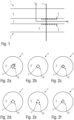
- Figure 1 1 shows a schematic representation of a longitudinal section through an embodiment of a fiber optic sensor 1.
- the longitudinal section runs in the axial direction z of the optical fiber 3 of the sensor 1, which represents the direction of light propagation in the core 5 of the optical fiber 3, which is made, for example, from a glass fiber.
- the core 5 runs centrally in the axial direction and extends essentially over the entire length of the optical fiber 3.
- r i.e. perpendicular to the axial direction of the optical fiber 3
- the core 5 is surrounded by a jacket 6, e.g. made of plastic, for its protection.
- the axial direction and the radial direction are shown as rz coordinate axes.
- the Bragg gratings 20 symbolically represented as points, all run through the cross-sectional plane of the associated optical waveguide 3. i.e. they lie on the cross-sectional planes.
- the Bragg gratings 20 have a maximum diameter less than half the maximum diameter of the core 5.
- each section there are four Bragg gratings 20 running through the cross-sectional plane arranged.
- the four Bragg gratings 20 are all arranged in the inner edge region of the cladding 6.
- all Bragg gratings 20 are arranged on the edge of the core 5, whereas in Figure 2c all Bragg gratings 20 are arranged in an outer edge region of the core 5.
- the four Bragg gratings 20 are each arranged symmetrically around the center of the core 5.
- FIGs 3a and 3b the principle underlying the method according to the invention for determining a deformation, ie a curvature and/or torsion, of the optical waveguide 3 of a fiber optic sensor is shown.
- an optical waveguide 3 of a fiber optic sensor with two Bragg gratings 8,9 is shown undeformed, ie running straight.
- Figure 3b This is shown curved.
- the intensity distribution I (Mode Field Intensity Distribution) of the light introduced to determine the deformation is shown in the form of its spatial mode field distribution in the optical waveguide 3.
- the intensity distribution corresponds to a Gaussian distribution 30, which is plotted in a tilted xy coordinate system.
- the Gaussian distribution 30 is evenly distributed around the center of the core 5, whereas in a curved waveguide the Gaussian distribution 30 is shifted in the radial direction, thus extending further into the cladding 6 of the optical waveguide.
- the lower part of the figures shows the light intensity 35 (intensity signal) after the interaction of a spectrally broadband light field with a Bragg grating designed as a periodic index modulation at the edge of the mode field, i.e. the intensity of a reflected spectrum. It can be seen how the intensity signal 35 changes with a bend of the optical waveguide 3.
- a structure with periodic index modulation i.e. a Bragg grating
- the intensity (I) of the reflected light changes when the mode field is shifted as it interacts with the structure. This leads to a change in the light intensity reflected by the Bragg grating, which can be detected or used to measure the deformation.
- the intensity of the reflected light 35 of the individual Bragg gratings 8, 9 has changed due to the curvature.
- the intensity corresponding to the upper Bragg grating (BG1) 8 in the figure has increased, and the intensity corresponding to the lower Bragg grating (BG2) 9 in the figure has decreased.
- the displacement of the mode field and, from this, the local curvature of the fiber can be calculated. Interpolation of many such measurement points allows a complete reconstruction of the three-dimensional shape of the fiber and thus of the optical waveguide in space. Similar effects also occur during torsion and stretching of the optical waveguide and are evaluated for their determination.
- the method according to the invention for determining the curvature and/or torsion of the optical waveguide of a fiber optic sensor comprises the following method steps: Provision of reference data (calibration parameters) of intensities of reflected light components (amplitude signals) of light coupled into the optical waveguide, in particular as a function of known reference deformations of the optical waveguide, Measurement of at least one light intensity of reflected light components of light coupled into the optical waveguide, wherein the optical waveguide has a deformation to be determined, and Determination of the Deformation, ie evaluation of the light intensities of the reflected light components, by comparing the light intensity with the reference data.
- the reference data can be calculated by simulation or measured.
- the reflected light components, ie their light intensities can be evaluated particularly well to determine the deformation if the Bragg gratings are arranged in a geometrical arrangement according to the Figures 2 are introduced into the optical fiber.
- a possible evaluation of amplitude signals of the fiber optic sensor is based on the comparison of the current amplitude ratios of all sensors involved in a measuring plane, i.e. Bragg gratings, with the calibration parameters that correspond to the amplitude ratios of the non-curved sensor.
- the determination of the amplitude signals can be achieved using all known evaluation methods for Bragg gratings, e.g., conventional spectrometer-based FBG evaluation units, arrayed waveguide grading (AWG) systems, tunable laser diodes, time-of-flight selective interrogators in the frequency or time domain, or even with additional Bragg gratings. It can be achieved either by measuring an absolute value or by fitting a mathematical function to the raw data signal.
- AMG arrayed waveguide grading
- Every possible ratio of Bragg gratings of a measurement plane ie Bragg gratings on a cross-sectional plane of the optical fiber, can be assigned to exactly one shift of the corresponding mode field.
- fiber optic sensors with four orthogonal gratings as in the Figures 2d to f, curvatures of the optical waveguide in both spatial directions can be determined separately.
- a unique displacement can be determined for three gratings positioned in an arbitrary two-dimensional arrangement using geometric and numerical methods. This displacement corresponds to the actually measured relative intensities of the three gratings.
- simulated (i.e., calculated) mode fields can be stored as reference data for different curvatures. These mode fields exhibit a certain distortion of the intensity distribution depending on the radius of the curvature. This, in combination with numerical solution methods, promises the greatest possible accuracy in converting measured signal amplitudes into the deformation to be determined, e.g., curvature.
- the displacement of the mode field can also be determined on the Y-axis between the third Bragg grating and the new virtual Bragg grating analogously to points 4 and 5 above.
- the direction of curvature and the radius of the bend of the glass fiber can be directly determined.
Landscapes
- Physics & Mathematics (AREA)
- General Physics & Mathematics (AREA)
- Optics & Photonics (AREA)
- Optical Transform (AREA)
- Length Measuring Devices By Optical Means (AREA)
- Investigating Or Analysing Materials By Optical Means (AREA)
Claims (10)
- Procédé pour déterminer une courbure et/ou une torsion d'un guide d'ondes optiques (3) d'un capteur à fibres optiques (1) comprenant un guide d'ondes optiques (3) qui présente une direction axiale orientée dans une direction de propagation de la lumière et une direction radiale orientée perpendiculairement à celle-ci,dans lequel le guide d'ondes optiques (3) présente un cœur (5) de conduction de la lumière, qui s'étend au centre dans la direction axiale et au moins sensiblement sur toute la longueur du guide d'ondes optiques (3), et une gaine (6) qui entoure le cœur (5) dans la direction radiale, etil est prévu au moins une portion du guide d'ondes optiques (3), qui s'étend dans la direction axiale et qui comprend au moins deux réseaux de Bragg (8, 9, 10, 11) intégrés dans celle-ci et passant par un plan de section transversale (11) commun, situé dans la direction radiale, à travers le guide d'ondes optiques (3),les réseaux de Bragg (8, 9, 20) sont intégrés dans le cœur (5) et/ou sur la limite entre le cœur (5) et la gaine (6) et/ou dans une zone de bord intérieure de la gaine (6) à l'intérieur d'une zone d'évanescence de la lumière, etau moins certains des réseaux de Bragg (8, 9, 20) présentent des constantes de réseau différentes,comprenant les étapes de procédé consistant à :(a) mettre à disposition des données de référence d'intensités de parts de lumière réfléchies de la lumière injectée dans le guide d'ondes optiques (3),(b) mesurer au moins une intensité lumineuse (35) de parts de lumière réfléchies de la lumière injectée dans le guide d'ondes optiques (3), le guide d'ondes optiques (3) présentant une déformation à déterminer, et(c) déterminer la déformation par comparaison de l'intensité lumineuse (35) avec les données de référence,un multiplexage en longueur d'onde et/ou un multiplexage temporel de la lumière injectée dans le guide d'ondes optiques étant effectué pour déterminer la déformation.
- Procédé selon la revendication 1,
dans lequel la zone de bord intérieure de la gaine (6) s'étend en direction radiale dans la gaine (6) sur moins de dix pour cent de l'épaisseur de la gaine (6). - Procédé selon la revendication 1 ou 2,
dans lequel trois réseaux de Bragg (8, 9, 20) passant par le plan de section transversale (11) sont disposés dans ladite portion. - Procédé selon la revendication 3,
dans lequel l'un des réseaux de Bragg (8, 9, 20) est disposé au centre du cœur (5) et deux des réseaux de Bragg (8, 9, 20) sont disposés dans la zone de bord intérieure de la gaine (6), ou les trois réseaux de Bragg (8, 9, 20) sont disposés dans la zone de bord intérieure de la gaine (6). - Procédé selon l'une des revendications 1 ou 2,dans lequel quatre réseaux de Bragg (8, 9, 20) passant par le plan de section transversale (11) sont disposés dans ladite portion,en particulier, les quatre réseaux de Bragg (8, 9, 20) sont tous disposés dans la zone de bord intérieure de la gaine (6) ou sont tous disposés sur le bord du cœur (5) ou sont tous disposés dans une zone de bord extérieure du cœur (5).
- Procédé selon l'une des revendications 1 à 5,
dans lequel les réseaux de Bragg (8, 9, 20) sont répartis symétriquement autour du centre du cœur (5). - Procédé selon l'une des revendications 1 à 6,
dans lequel les réseaux de Bragg (8, 9, 20) présentent un diamètre maximal inférieur à la moitié du diamètre maximal du cœur (5). - Procédé selon l'une des revendications 1 à 7,
dans lequel on mesure au moins deux intensités lumineuses (35), une déformation tridimensionnelle étant déterminée par comparaison des intensités lumineuses (35) avec les données de référence. - Procédé selon l'une des revendications 1 à 8,
dans lequel, lors de la détermination de la déformation, on procède à une évaluation des intensités lumineuses (35) au moyen d'un spectromètre et/ou d'un élément filtrant AWG et/ou d'un élément filtrant FBG. - Procédé selon l'une des revendications 1 à 9,
dans lequel la mise à disposition de données de référence d'intensités de parts de lumière réfléchies de la lumière injectée dans les guides d'ondes optiques (39) est effectuée en fonction de déformations de référence connues du guide d'ondes optiques.
Applications Claiming Priority (2)
| Application Number | Priority Date | Filing Date | Title |
|---|---|---|---|
| DE102016214887.7A DE102016214887A1 (de) | 2016-08-10 | 2016-08-10 | Faseroptischer Sensor sowie Verfahren zu dessen Herstellung und Verwendung |
| PCT/EP2017/070006 WO2018029165A1 (fr) | 2016-08-10 | 2017-08-08 | Procédé permettant de déterminer la courbure et/ou la torsion d'un guide d'ondes optiques |
Publications (2)
| Publication Number | Publication Date |
|---|---|
| EP3497409A1 EP3497409A1 (fr) | 2019-06-19 |
| EP3497409B1 true EP3497409B1 (fr) | 2025-04-16 |
Family
ID=59683518
Family Applications (1)
| Application Number | Title | Priority Date | Filing Date |
|---|---|---|---|
| EP17755093.6A Active EP3497409B1 (fr) | 2016-08-10 | 2017-08-08 | Procédé permettant de déterminer la courbure et/ou la torsion d'un guide d'ondes optiques |
Country Status (5)
| Country | Link |
|---|---|
| US (1) | US10969541B2 (fr) |
| EP (1) | EP3497409B1 (fr) |
| JP (1) | JP6997186B2 (fr) |
| DE (1) | DE102016214887A1 (fr) |
| WO (1) | WO2018029165A1 (fr) |
Families Citing this family (10)
| Publication number | Priority date | Publication date | Assignee | Title |
|---|---|---|---|---|
| DE102019123468B3 (de) | 2019-09-02 | 2021-01-07 | Fisens Gmbh | Vorrichtung für optische Anwendungen |
| WO2021047779A1 (fr) | 2019-09-12 | 2021-03-18 | Fraunhofer-Gesellschaft zur Förderung der angewandten Forschung e.V. | Procédé et dispositif pour déterminer la forme d'un guide d'onde optique et dispositif pour produire des données d'apprentissage pour un réseau neuronal |
| US20230137926A1 (en) * | 2020-03-13 | 2023-05-04 | Ofs Fitel, Llc | System for measuring microbends and arbitrary microdeformations along a three-dimensional space |
| US11822084B2 (en) * | 2020-04-02 | 2023-11-21 | Google Llc | Direction of light propagation in wearable optical devices |
| WO2021246497A1 (fr) * | 2020-06-05 | 2021-12-09 | 日本電信電話株式会社 | Système de mesure de forme et procédé de mesure de forme |
| WO2022029871A1 (fr) * | 2020-08-04 | 2022-02-10 | 日本電信電話株式会社 | Fibre optique |
| WO2022029872A1 (fr) * | 2020-08-04 | 2022-02-10 | 日本電信電話株式会社 | Fibre optique et système de transmission à fibre optique |
| TWI750103B (zh) * | 2021-07-16 | 2021-12-11 | 明志科技大學 | 全固態鋰電池之鋰箔陽極的製備方法 |
| CN116336970B (zh) * | 2022-12-28 | 2023-10-03 | 深圳大学 | 光纤包层光栅传感器及其测斜方法和光纤包层光栅测斜仪 |
| CN116295070B (zh) * | 2023-01-18 | 2025-11-25 | 武汉理工大学 | 一种单芯结构的光纤光栅形状传感器和形状传感测量方法 |
Citations (1)
| Publication number | Priority date | Publication date | Assignee | Title |
|---|---|---|---|---|
| US20070297712A1 (en) * | 2006-06-08 | 2007-12-27 | Chiara Meneghini | Optical fiber sensor and method |
Family Cites Families (16)
| Publication number | Priority date | Publication date | Assignee | Title |
|---|---|---|---|---|
| JP4053645B2 (ja) | 1998-02-03 | 2008-02-27 | 株式会社フジクラ | 光導波路グレーティングセンサ |
| GB0410821D0 (en) * | 2004-05-14 | 2004-06-16 | Univ Aston | Laser inscribed structures |
| US7376307B2 (en) * | 2004-10-29 | 2008-05-20 | Matsushita Electric Industrial Co., Ltd | Multimode long period fiber bragg grating machined by ultrafast laser direct writing |
| US7587110B2 (en) | 2005-03-22 | 2009-09-08 | Panasonic Corporation | Multicore optical fiber with integral diffractive elements machined by ultrafast laser direct writing |
| DE102005030753B4 (de) * | 2005-06-29 | 2018-04-12 | Hottinger Baldwin Messtechnik Gmbh | Optischer Dehnungsmessstreifen |
| JP5136747B2 (ja) | 2007-02-01 | 2013-02-06 | 国立大学法人 名古屋工業大学 | 曲がり度合い検出装置およびそれを用いた曲がり度合い検出方法 |
| JP5185773B2 (ja) | 2008-10-28 | 2013-04-17 | オリンパスメディカルシステムズ株式会社 | 形状測定装置 |
| US20100166358A1 (en) * | 2008-12-30 | 2010-07-01 | Daniel Homa | Dual Fiber Grating and Methods of Making and Using Same |
| JP2011180133A (ja) | 2010-02-03 | 2011-09-15 | Soka Univ | 光ファイバセンサ及びその製造方法 |
| WO2012101562A1 (fr) | 2011-01-28 | 2012-08-02 | Koninklijke Philips Electronics N.V. | Capteur optique de fibre pour déterminer une forme tridimensionnelle |
| JP6091052B2 (ja) | 2011-04-05 | 2017-03-08 | オリンパス株式会社 | 光学式曲がり測定装置 |
| US8701500B2 (en) * | 2011-12-02 | 2014-04-22 | Lake Shore Cryotronics, Inc. | Method and apparatus for fixing strained optical fibers against creep and temperature and strain sensors using said technology |
| DE102012214441B4 (de) | 2012-08-14 | 2020-08-06 | Fraunhofer-Gesellschaft zur Förderung der angewandten Forschung e.V. | Messverfahren |
| JP6274775B2 (ja) | 2013-08-09 | 2018-02-07 | オリンパス株式会社 | 光学式センサシステムと、光学式センサシステムを有する内視鏡 |
| DE102014211918A1 (de) | 2014-06-23 | 2015-12-24 | Fraunhofer-Gesellschaft zur Förderung der angewandten Forschung e.V. | Faseroptischer Sensor sowie Verfahren zu dessen Herstellung und Verwendung |
| JP6413011B2 (ja) | 2015-03-13 | 2018-10-24 | オリンパス株式会社 | 光学式曲がり測定装置及び管状挿入体 |
-
2016
- 2016-08-10 DE DE102016214887.7A patent/DE102016214887A1/de active Pending
-
2017
- 2017-08-08 US US16/320,636 patent/US10969541B2/en active Active
- 2017-08-08 EP EP17755093.6A patent/EP3497409B1/fr active Active
- 2017-08-08 WO PCT/EP2017/070006 patent/WO2018029165A1/fr not_active Ceased
- 2017-08-08 JP JP2019529688A patent/JP6997186B2/ja active Active
Patent Citations (1)
| Publication number | Priority date | Publication date | Assignee | Title |
|---|---|---|---|---|
| US20070297712A1 (en) * | 2006-06-08 | 2007-12-27 | Chiara Meneghini | Optical fiber sensor and method |
Also Published As
| Publication number | Publication date |
|---|---|
| DE102016214887A1 (de) | 2018-02-15 |
| WO2018029165A1 (fr) | 2018-02-15 |
| JP2019531487A (ja) | 2019-10-31 |
| US10969541B2 (en) | 2021-04-06 |
| JP6997186B2 (ja) | 2022-01-17 |
| US20190170930A1 (en) | 2019-06-06 |
| EP3497409A1 (fr) | 2019-06-19 |
Similar Documents
| Publication | Publication Date | Title |
|---|---|---|
| EP3497409B1 (fr) | Procédé permettant de déterminer la courbure et/ou la torsion d'un guide d'ondes optiques | |
| DE2819590C2 (de) | Vorrichtung zur Messung der in einem festen Körper vorliegenden Spannung | |
| EP2979057B1 (fr) | Capteur à fibre optique et son utilisation | |
| EP3158296B1 (fr) | Capteur à fibre optique ainsi que procédé pour sa fabrication et son utilisation | |
| EP3056934B1 (fr) | Tete de mesure d'un dispositif endoscopique et procede d'inspection et mesure d'un objet | |
| DE60014631T2 (de) | Dehnungsmessung | |
| DE102015218539B4 (de) | Optische Positionsmesseinrichtung | |
| DE102012214441B4 (de) | Messverfahren | |
| EP4025885B1 (fr) | Dispositif pour applications optiques | |
| DE102019132569B3 (de) | Multikernfaser mit Multikern-Faserkomponenten sowie Verfahren zu ihrer Herstellung | |
| WO2017081316A1 (fr) | Composant optique et procédé de fabrication | |
| WO2011098059A1 (fr) | Composant optique | |
| DE202010002129U1 (de) | Sensor zum Erfassen von Relativbewegungen zwischen Objekten | |
| DE102011080328B4 (de) | Wellenleiter und Verbindungselement | |
| EP3776028B1 (fr) | Dispositif et procédé de transmission de lumière entre au moins un composant optoélectronique et au moins un guide d'ondes optiques | |
| EP3321641B1 (fr) | Reseau pour un dispositif de mesure de position optique | |
| EP3311108B1 (fr) | Dispositif et procédé pour la détermination d'une déformation d'une structure flexible tridimensionnelle | |
| EP4028720B1 (fr) | Procédé et dispositif pour déterminer la forme d'un guide d'onde optique et dispositif pour produire des données d'apprentissage pour un réseau neuronal | |
| EP2778647B1 (fr) | Procédé de caractérisation d'une fibre optique | |
| EP4528242A1 (fr) | Dispositif de mesure et son procédé de fabrication et d'utilisation | |
| AT517632B1 (de) | Optischer Krümmungssensor | |
| DE102020113675A1 (de) | Rollwinkelmessgerät und Verfahren zum Messen eines Rollwinkels | |
| WO2022189339A1 (fr) | Dispositif et procédé pour la détection d'un rayonnement électromagnétique | |
| DE102019101630A1 (de) | Faseroptischer Sensor und Verfahren | |
| DE202015106397U1 (de) | Biegemessvorrichtung mit Lichtwellenleiter |
Legal Events
| Date | Code | Title | Description |
|---|---|---|---|
| STAA | Information on the status of an ep patent application or granted ep patent |
Free format text: STATUS: UNKNOWN |
|
| STAA | Information on the status of an ep patent application or granted ep patent |
Free format text: STATUS: THE INTERNATIONAL PUBLICATION HAS BEEN MADE |
|
| PUAI | Public reference made under article 153(3) epc to a published international application that has entered the european phase |
Free format text: ORIGINAL CODE: 0009012 |
|
| STAA | Information on the status of an ep patent application or granted ep patent |
Free format text: STATUS: REQUEST FOR EXAMINATION WAS MADE |
|
| 17P | Request for examination filed |
Effective date: 20190307 |
|
| AK | Designated contracting states |
Kind code of ref document: A1 Designated state(s): AL AT BE BG CH CY CZ DE DK EE ES FI FR GB GR HR HU IE IS IT LI LT LU LV MC MK MT NL NO PL PT RO RS SE SI SK SM TR |
|
| AX | Request for extension of the european patent |
Extension state: BA ME |
|
| DAV | Request for validation of the european patent (deleted) | ||
| DAX | Request for extension of the european patent (deleted) | ||
| STAA | Information on the status of an ep patent application or granted ep patent |
Free format text: STATUS: EXAMINATION IS IN PROGRESS |
|
| 17Q | First examination report despatched |
Effective date: 20210608 |
|
| RAP3 | Party data changed (applicant data changed or rights of an application transferred) |
Owner name: PHOTONIK INKUBATOR GMBH Owner name: FRAUNHOFER-GESELLSCHAFT ZUR FOERDERUNG DER ANGEWANDTEN FORSCHUNG E.V. |
|
| GRAP | Despatch of communication of intention to grant a patent |
Free format text: ORIGINAL CODE: EPIDOSNIGR1 |
|
| STAA | Information on the status of an ep patent application or granted ep patent |
Free format text: STATUS: GRANT OF PATENT IS INTENDED |
|
| INTG | Intention to grant announced |
Effective date: 20241204 |
|
| GRAS | Grant fee paid |
Free format text: ORIGINAL CODE: EPIDOSNIGR3 |
|
| RAP1 | Party data changed (applicant data changed or rights of an application transferred) |
Owner name: FRAUNHOFER-GESELLSCHAFT ZUR FOERDERUNGDER ANGEWANDTEN FORSCHUNG E.V. |
|
| GRAA | (expected) grant |
Free format text: ORIGINAL CODE: 0009210 |
|
| STAA | Information on the status of an ep patent application or granted ep patent |
Free format text: STATUS: THE PATENT HAS BEEN GRANTED |
|
| AK | Designated contracting states |
Kind code of ref document: B1 Designated state(s): AL AT BE BG CH CY CZ DE DK EE ES FI FR GB GR HR HU IE IS IT LI LT LU LV MC MK MT NL NO PL PT RO RS SE SI SK SM TR |
|
| REG | Reference to a national code |
Ref country code: GB Ref legal event code: FG4D Free format text: NOT ENGLISH |
|
| REG | Reference to a national code |
Ref country code: CH Ref legal event code: EP |
|
| REG | Reference to a national code |
Ref country code: IE Ref legal event code: FG4D Free format text: LANGUAGE OF EP DOCUMENT: GERMAN |
|
| REG | Reference to a national code |
Ref country code: DE Ref legal event code: R096 Ref document number: 502017016799 Country of ref document: DE |
|
| REG | Reference to a national code |
Ref country code: NL Ref legal event code: MP Effective date: 20250416 |
|
| PG25 | Lapsed in a contracting state [announced via postgrant information from national office to epo] |
Ref country code: NL Free format text: LAPSE BECAUSE OF FAILURE TO SUBMIT A TRANSLATION OF THE DESCRIPTION OR TO PAY THE FEE WITHIN THE PRESCRIBED TIME-LIMIT Effective date: 20250416 |
|
| PG25 | Lapsed in a contracting state [announced via postgrant information from national office to epo] |
Ref country code: PT Free format text: LAPSE BECAUSE OF FAILURE TO SUBMIT A TRANSLATION OF THE DESCRIPTION OR TO PAY THE FEE WITHIN THE PRESCRIBED TIME-LIMIT Effective date: 20250818 Ref country code: FI Free format text: LAPSE BECAUSE OF FAILURE TO SUBMIT A TRANSLATION OF THE DESCRIPTION OR TO PAY THE FEE WITHIN THE PRESCRIBED TIME-LIMIT Effective date: 20250416 Ref country code: ES Free format text: LAPSE BECAUSE OF FAILURE TO SUBMIT A TRANSLATION OF THE DESCRIPTION OR TO PAY THE FEE WITHIN THE PRESCRIBED TIME-LIMIT Effective date: 20250416 |
|
| PGFP | Annual fee paid to national office [announced via postgrant information from national office to epo] |
Ref country code: DE Payment date: 20250819 Year of fee payment: 9 |
|
| REG | Reference to a national code |
Ref country code: LT Ref legal event code: MG9D |
|
| PG25 | Lapsed in a contracting state [announced via postgrant information from national office to epo] |
Ref country code: GR Free format text: LAPSE BECAUSE OF FAILURE TO SUBMIT A TRANSLATION OF THE DESCRIPTION OR TO PAY THE FEE WITHIN THE PRESCRIBED TIME-LIMIT Effective date: 20250717 Ref country code: NO Free format text: LAPSE BECAUSE OF FAILURE TO SUBMIT A TRANSLATION OF THE DESCRIPTION OR TO PAY THE FEE WITHIN THE PRESCRIBED TIME-LIMIT Effective date: 20250716 |
|
| PG25 | Lapsed in a contracting state [announced via postgrant information from national office to epo] |
Ref country code: PL Free format text: LAPSE BECAUSE OF FAILURE TO SUBMIT A TRANSLATION OF THE DESCRIPTION OR TO PAY THE FEE WITHIN THE PRESCRIBED TIME-LIMIT Effective date: 20250416 |
|
| PG25 | Lapsed in a contracting state [announced via postgrant information from national office to epo] |
Ref country code: BG Free format text: LAPSE BECAUSE OF FAILURE TO SUBMIT A TRANSLATION OF THE DESCRIPTION OR TO PAY THE FEE WITHIN THE PRESCRIBED TIME-LIMIT Effective date: 20250416 |
|
| PGFP | Annual fee paid to national office [announced via postgrant information from national office to epo] |
Ref country code: GB Payment date: 20250825 Year of fee payment: 9 |
|
| PG25 | Lapsed in a contracting state [announced via postgrant information from national office to epo] |
Ref country code: HR Free format text: LAPSE BECAUSE OF FAILURE TO SUBMIT A TRANSLATION OF THE DESCRIPTION OR TO PAY THE FEE WITHIN THE PRESCRIBED TIME-LIMIT Effective date: 20250416 |
|
| PGFP | Annual fee paid to national office [announced via postgrant information from national office to epo] |
Ref country code: FR Payment date: 20250821 Year of fee payment: 9 |
|
| PG25 | Lapsed in a contracting state [announced via postgrant information from national office to epo] |
Ref country code: RS Free format text: LAPSE BECAUSE OF FAILURE TO SUBMIT A TRANSLATION OF THE DESCRIPTION OR TO PAY THE FEE WITHIN THE PRESCRIBED TIME-LIMIT Effective date: 20250716 |
|
| PG25 | Lapsed in a contracting state [announced via postgrant information from national office to epo] |
Ref country code: IS Free format text: LAPSE BECAUSE OF FAILURE TO SUBMIT A TRANSLATION OF THE DESCRIPTION OR TO PAY THE FEE WITHIN THE PRESCRIBED TIME-LIMIT Effective date: 20250816 |
|
| PG25 | Lapsed in a contracting state [announced via postgrant information from national office to epo] |
Ref country code: LV Free format text: LAPSE BECAUSE OF FAILURE TO SUBMIT A TRANSLATION OF THE DESCRIPTION OR TO PAY THE FEE WITHIN THE PRESCRIBED TIME-LIMIT Effective date: 20250416 |
|
| PG25 | Lapsed in a contracting state [announced via postgrant information from national office to epo] |
Ref country code: SM Free format text: LAPSE BECAUSE OF FAILURE TO SUBMIT A TRANSLATION OF THE DESCRIPTION OR TO PAY THE FEE WITHIN THE PRESCRIBED TIME-LIMIT Effective date: 20250416 Ref country code: DK Free format text: LAPSE BECAUSE OF FAILURE TO SUBMIT A TRANSLATION OF THE DESCRIPTION OR TO PAY THE FEE WITHIN THE PRESCRIBED TIME-LIMIT Effective date: 20250416 |
|
| REG | Reference to a national code |
Ref country code: DE Ref legal event code: R097 Ref document number: 502017016799 Country of ref document: DE |
|
| PG25 | Lapsed in a contracting state [announced via postgrant information from national office to epo] |
Ref country code: CZ Free format text: LAPSE BECAUSE OF FAILURE TO SUBMIT A TRANSLATION OF THE DESCRIPTION OR TO PAY THE FEE WITHIN THE PRESCRIBED TIME-LIMIT Effective date: 20250416 |
|
| PG25 | Lapsed in a contracting state [announced via postgrant information from national office to epo] |
Ref country code: EE Free format text: LAPSE BECAUSE OF FAILURE TO SUBMIT A TRANSLATION OF THE DESCRIPTION OR TO PAY THE FEE WITHIN THE PRESCRIBED TIME-LIMIT Effective date: 20250416 |
|
| PG25 | Lapsed in a contracting state [announced via postgrant information from national office to epo] |
Ref country code: SK Free format text: LAPSE BECAUSE OF FAILURE TO SUBMIT A TRANSLATION OF THE DESCRIPTION OR TO PAY THE FEE WITHIN THE PRESCRIBED TIME-LIMIT Effective date: 20250416 Ref country code: RO Free format text: LAPSE BECAUSE OF FAILURE TO SUBMIT A TRANSLATION OF THE DESCRIPTION OR TO PAY THE FEE WITHIN THE PRESCRIBED TIME-LIMIT Effective date: 20250416 |
|
| PG25 | Lapsed in a contracting state [announced via postgrant information from national office to epo] |
Ref country code: IT Free format text: LAPSE BECAUSE OF FAILURE TO SUBMIT A TRANSLATION OF THE DESCRIPTION OR TO PAY THE FEE WITHIN THE PRESCRIBED TIME-LIMIT Effective date: 20250416 |
|
| PLBE | No opposition filed within time limit |
Free format text: ORIGINAL CODE: 0009261 |
|
| STAA | Information on the status of an ep patent application or granted ep patent |
Free format text: STATUS: NO OPPOSITION FILED WITHIN TIME LIMIT |
|
| REG | Reference to a national code |
Ref country code: CH Ref legal event code: L10 Free format text: ST27 STATUS EVENT CODE: U-0-0-L10-L00 (AS PROVIDED BY THE NATIONAL OFFICE) Effective date: 20260225 |
|
| REG | Reference to a national code |
Ref country code: CH Ref legal event code: H13 Free format text: ST27 STATUS EVENT CODE: U-0-0-H10-H13 (AS PROVIDED BY THE NATIONAL OFFICE) Effective date: 20260324 |
|
| 26N | No opposition filed |
Effective date: 20260119 |
|
| PG25 | Lapsed in a contracting state [announced via postgrant information from national office to epo] |
Ref country code: MC Free format text: LAPSE BECAUSE OF FAILURE TO SUBMIT A TRANSLATION OF THE DESCRIPTION OR TO PAY THE FEE WITHIN THE PRESCRIBED TIME-LIMIT Effective date: 20250416 |
|
| PG25 | Lapsed in a contracting state [announced via postgrant information from national office to epo] |
Ref country code: LU Free format text: LAPSE BECAUSE OF NON-PAYMENT OF DUE FEES Effective date: 20250808 |
|
| PG25 | Lapsed in a contracting state [announced via postgrant information from national office to epo] |
Ref country code: CH Free format text: LAPSE BECAUSE OF NON-PAYMENT OF DUE FEES Effective date: 20250831 |