EP3497423B1 - Vorrichtung und verfahren zur leistungscharakterisierung einer augennahen multikonfigurationsanzeige - Google Patents
Vorrichtung und verfahren zur leistungscharakterisierung einer augennahen multikonfigurationsanzeige Download PDFInfo
- Publication number
- EP3497423B1 EP3497423B1 EP17794831.2A EP17794831A EP3497423B1 EP 3497423 B1 EP3497423 B1 EP 3497423B1 EP 17794831 A EP17794831 A EP 17794831A EP 3497423 B1 EP3497423 B1 EP 3497423B1
- Authority
- EP
- European Patent Office
- Prior art keywords
- image
- dut
- aperture
- fov
- measurement
- Prior art date
- Legal status (The legal status is an assumption and is not a legal conclusion. Google has not performed a legal analysis and makes no representation as to the accuracy of the status listed.)
- Active
Links
Images



Classifications
-
- H—ELECTRICITY
- H04—ELECTRIC COMMUNICATION TECHNIQUE
- H04N—PICTORIAL COMMUNICATION, e.g. TELEVISION
- H04N17/00—Diagnosis, testing or measuring for television systems or their details
- H04N17/04—Diagnosis, testing or measuring for television systems or their details for receivers
-
- G—PHYSICS
- G01—MEASURING; TESTING
- G01M—TESTING STATIC OR DYNAMIC BALANCE OF MACHINES OR STRUCTURES; TESTING OF STRUCTURES OR APPARATUS, NOT OTHERWISE PROVIDED FOR
- G01M11/00—Testing of optical apparatus; Testing structures by optical methods not otherwise provided for
- G01M11/02—Testing optical properties
- G01M11/0242—Testing optical properties by measuring geometrical properties or aberrations
- G01M11/0257—Testing optical properties by measuring geometrical properties or aberrations by analyzing the image formed by the object to be tested
-
- G—PHYSICS
- G01—MEASURING; TESTING
- G01J—MEASUREMENT OF INTENSITY, VELOCITY, SPECTRAL CONTENT, POLARISATION, PHASE OR PULSE CHARACTERISTICS OF INFRARED, VISIBLE OR ULTRAVIOLET LIGHT; COLORIMETRY; RADIATION PYROMETRY
- G01J1/00—Photometry, e.g. photographic exposure meter
-
- G—PHYSICS
- G01—MEASURING; TESTING
- G01J—MEASUREMENT OF INTENSITY, VELOCITY, SPECTRAL CONTENT, POLARISATION, PHASE OR PULSE CHARACTERISTICS OF INFRARED, VISIBLE OR ULTRAVIOLET LIGHT; COLORIMETRY; RADIATION PYROMETRY
- G01J3/00—Spectrometry; Spectrophotometry; Monochromators; Measuring colours
- G01J3/02—Details
- G01J3/0205—Optical elements not provided otherwise, e.g. optical manifolds, diffusers, windows
- G01J3/0208—Optical elements not provided otherwise, e.g. optical manifolds, diffusers, windows using focussing or collimating elements, e.g. lenses or mirrors; performing aberration correction
-
- G—PHYSICS
- G01—MEASURING; TESTING
- G01J—MEASUREMENT OF INTENSITY, VELOCITY, SPECTRAL CONTENT, POLARISATION, PHASE OR PULSE CHARACTERISTICS OF INFRARED, VISIBLE OR ULTRAVIOLET LIGHT; COLORIMETRY; RADIATION PYROMETRY
- G01J3/00—Spectrometry; Spectrophotometry; Monochromators; Measuring colours
- G01J3/02—Details
- G01J3/0205—Optical elements not provided otherwise, e.g. optical manifolds, diffusers, windows
- G01J3/0218—Optical elements not provided otherwise, e.g. optical manifolds, diffusers, windows using optical fibers
-
- G—PHYSICS
- G01—MEASURING; TESTING
- G01J—MEASUREMENT OF INTENSITY, VELOCITY, SPECTRAL CONTENT, POLARISATION, PHASE OR PULSE CHARACTERISTICS OF INFRARED, VISIBLE OR ULTRAVIOLET LIGHT; COLORIMETRY; RADIATION PYROMETRY
- G01J3/00—Spectrometry; Spectrophotometry; Monochromators; Measuring colours
- G01J3/02—Details
- G01J3/0205—Optical elements not provided otherwise, e.g. optical manifolds, diffusers, windows
- G01J3/0237—Adjustable, e.g. focussing
-
- G—PHYSICS
- G01—MEASURING; TESTING
- G01J—MEASUREMENT OF INTENSITY, VELOCITY, SPECTRAL CONTENT, POLARISATION, PHASE OR PULSE CHARACTERISTICS OF INFRARED, VISIBLE OR ULTRAVIOLET LIGHT; COLORIMETRY; RADIATION PYROMETRY
- G01J3/00—Spectrometry; Spectrophotometry; Monochromators; Measuring colours
- G01J3/02—Details
- G01J3/0205—Optical elements not provided otherwise, e.g. optical manifolds, diffusers, windows
- G01J3/0248—Optical elements not provided otherwise, e.g. optical manifolds, diffusers, windows using a sighting port, e.g. camera or human eye
-
- G—PHYSICS
- G01—MEASURING; TESTING
- G01J—MEASUREMENT OF INTENSITY, VELOCITY, SPECTRAL CONTENT, POLARISATION, PHASE OR PULSE CHARACTERISTICS OF INFRARED, VISIBLE OR ULTRAVIOLET LIGHT; COLORIMETRY; RADIATION PYROMETRY
- G01J3/00—Spectrometry; Spectrophotometry; Monochromators; Measuring colours
- G01J3/28—Investigating the spectrum
- G01J3/2823—Imaging spectrometer
-
- G—PHYSICS
- G01—MEASURING; TESTING
- G01J—MEASUREMENT OF INTENSITY, VELOCITY, SPECTRAL CONTENT, POLARISATION, PHASE OR PULSE CHARACTERISTICS OF INFRARED, VISIBLE OR ULTRAVIOLET LIGHT; COLORIMETRY; RADIATION PYROMETRY
- G01J3/00—Spectrometry; Spectrophotometry; Monochromators; Measuring colours
- G01J3/46—Measurement of colour; Colour measuring devices, e.g. colorimeters
- G01J3/50—Measurement of colour; Colour measuring devices, e.g. colorimeters using electric radiation detectors
- G01J3/506—Measurement of colour; Colour measuring devices, e.g. colorimeters using electric radiation detectors measuring the colour produced by screens, monitors, displays or CRTs
-
- G—PHYSICS
- G01—MEASURING; TESTING
- G01M—TESTING STATIC OR DYNAMIC BALANCE OF MACHINES OR STRUCTURES; TESTING OF STRUCTURES OR APPARATUS, NOT OTHERWISE PROVIDED FOR
- G01M11/00—Testing of optical apparatus; Testing structures by optical methods not otherwise provided for
- G01M11/02—Testing optical properties
- G01M11/04—Optical benches therefor
-
- G—PHYSICS
- G02—OPTICS
- G02B—OPTICAL ELEMENTS, SYSTEMS OR APPARATUS
- G02B1/00—Optical elements characterised by the material of which they are made; Optical coatings for optical elements
- G02B1/10—Optical coatings produced by application to, or surface treatment of, optical elements
- G02B1/11—Anti-reflection coatings
-
- G—PHYSICS
- G02—OPTICS
- G02B—OPTICAL ELEMENTS, SYSTEMS OR APPARATUS
- G02B27/00—Optical systems or apparatus not provided for by any of the groups G02B1/00 - G02B26/00, G02B30/00
- G02B27/10—Beam splitting or combining systems
- G02B27/14—Beam splitting or combining systems operating by reflection only
- G02B27/142—Coating structures, e.g. thin films multilayers
-
- G—PHYSICS
- G02—OPTICS
- G02B—OPTICAL ELEMENTS, SYSTEMS OR APPARATUS
- G02B27/00—Optical systems or apparatus not provided for by any of the groups G02B1/00 - G02B26/00, G02B30/00
- G02B27/30—Collimators
-
- G—PHYSICS
- G02—OPTICS
- G02B—OPTICAL ELEMENTS, SYSTEMS OR APPARATUS
- G02B7/00—Mountings, adjusting means, or light-tight connections, for optical elements
- G02B7/003—Alignment of optical elements
-
- G—PHYSICS
- G06—COMPUTING OR CALCULATING; COUNTING
- G06F—ELECTRIC DIGITAL DATA PROCESSING
- G06F3/00—Input arrangements for transferring data to be processed into a form capable of being handled by the computer; Output arrangements for transferring data from processing unit to output unit, e.g. interface arrangements
- G06F3/01—Input arrangements or combined input and output arrangements for interaction between user and computer
- G06F3/011—Arrangements for interaction with the human body, e.g. for user immersion in virtual reality
-
- H—ELECTRICITY
- H04—ELECTRIC COMMUNICATION TECHNIQUE
- H04N—PICTORIAL COMMUNICATION, e.g. TELEVISION
- H04N23/00—Cameras or camera modules comprising electronic image sensors; Control thereof
- H04N23/50—Constructional details
- H04N23/55—Optical parts specially adapted for electronic image sensors; Mounting thereof
-
- H—ELECTRICITY
- H04—ELECTRIC COMMUNICATION TECHNIQUE
- H04N—PICTORIAL COMMUNICATION, e.g. TELEVISION
- H04N23/00—Cameras or camera modules comprising electronic image sensors; Control thereof
- H04N23/60—Control of cameras or camera modules
- H04N23/63—Control of cameras or camera modules by using electronic viewfinders
-
- G—PHYSICS
- G02—OPTICS
- G02B—OPTICAL ELEMENTS, SYSTEMS OR APPARATUS
- G02B27/00—Optical systems or apparatus not provided for by any of the groups G02B1/00 - G02B26/00, G02B30/00
- G02B27/01—Head-up displays
- G02B27/0101—Head-up displays characterised by optical features
- G02B2027/0138—Head-up displays characterised by optical features comprising image capture systems, e.g. camera
-
- G—PHYSICS
- G02—OPTICS
- G02B—OPTICAL ELEMENTS, SYSTEMS OR APPARATUS
- G02B27/00—Optical systems or apparatus not provided for by any of the groups G02B1/00 - G02B26/00, G02B30/00
- G02B27/01—Head-up displays
- G02B27/0101—Head-up displays characterised by optical features
- G02B2027/014—Head-up displays characterised by optical features comprising information/image processing systems
-
- G—PHYSICS
- G02—OPTICS
- G02B—OPTICAL ELEMENTS, SYSTEMS OR APPARATUS
- G02B27/00—Optical systems or apparatus not provided for by any of the groups G02B1/00 - G02B26/00, G02B30/00
- G02B27/01—Head-up displays
- G02B27/017—Head mounted
- G02B27/0172—Head mounted characterised by optical features
-
- G—PHYSICS
- G02—OPTICS
- G02B—OPTICAL ELEMENTS, SYSTEMS OR APPARATUS
- G02B5/00—Optical elements other than lenses
- G02B5/04—Prisms
-
- G—PHYSICS
- G02—OPTICS
- G02B—OPTICAL ELEMENTS, SYSTEMS OR APPARATUS
- G02B5/00—Optical elements other than lenses
- G02B5/12—Reflex reflectors
-
- G—PHYSICS
- G02—OPTICS
- G02B—OPTICAL ELEMENTS, SYSTEMS OR APPARATUS
- G02B7/00—Mountings, adjusting means, or light-tight connections, for optical elements
- G02B7/02—Mountings, adjusting means, or light-tight connections, for optical elements for lenses
- G02B7/04—Mountings, adjusting means, or light-tight connections, for optical elements for lenses with mechanism for focusing or varying magnification
-
- H—ELECTRICITY
- H04—ELECTRIC COMMUNICATION TECHNIQUE
- H04N—PICTORIAL COMMUNICATION, e.g. TELEVISION
- H04N5/00—Details of television systems
- H04N5/222—Studio circuitry; Studio devices; Studio equipment
- H04N5/262—Studio circuits, e.g. for mixing, switching-over, change of character of image, other special effects ; Cameras specially adapted for the electronic generation of special effects
- H04N5/272—Means for inserting a foreground image in a background image, i.e. inlay, outlay
Definitions
- the present invention relates generally to optical system testing, and more particularly to performance characterization of multi configuration near eye displays.
- NED near eye displays
- VR virtual reality
- AR augmented reality
- a NED produces virtual image or scene, when positioned in front of and near the eye.
- the virtual scenes are binocularly positioned in front of the left and right eyes so that the virtual scenes are perceived by human stereoscopic vision as three-dimensional scenes.
- AR NEDs the user of the NED can see through the optics that are part of the virtual scene delivery system producing the illumination in the design eye box and see the virtual scene content superimposed on the real world.
- VR NEDs produce virtual scenes that cannot be seen through.
- a virtual scene is one that is presented to the eye of the observer with a lens or other optical conveyance so that it is collimated or nearly collimated.
- These types of devices are known as Near Eye Displays (NEDs) and Head Up Displays (HUDs).
- NEDs and HUDs are similar in that they both present virtual scenes to the eyes of display users.
- NEDs produce a virtual scene of both digital and analog content with pixel and raster scan display technologies.
- the virtual scenes are presented to the display by reflecting off of an optical component or surface referred to as a beam combiner, positioned at a distance typically more than 30 cm from the eyes and not attached to the display head.
- the HUD beam combiner can be thought of a window that when the display user looks through it, the virtual scene of the presented information is superimposed on the real world seen through and on the opposite side of the beam combiner similar to the AR NEDs.
- the virtual scene from NEDs and HUDs can be perceived by the eye if the entrance pupil of the eye is positioned within the area of the NED where the illumination from the virtual scene is projected by the optical design of the NED. This area is often referred to as the design eye box of the NED.
- the uniformity of the illumination in the plane of the eye entrance pupil can vary in intensity depending on the position within the plane bounded on the outside by the edges of the design eye box.
- a small (for example, 2 to 5 mm) diameter aperture is selected to simulate the entrance aperture pupil of the eye.
- All NEDs include three essential elements.
- the first is a display or source of some type, which generates light or a scene.
- the second is an optical system which projects the light into the viewer's eye(s).
- These optics are necessary because most people cannot comfortably focus on an object which appears to be close (e.g. less than two inches) to the eye.
- the optics create a virtual scene of the display source which appears to be at a sufficient distance for easy accommodation, and also allows for stereoscopic scene fusion if the device provides a 3D scene.
- the optics may combine the display output with a view of the actual scene surrounding the user (AR), or entirely block off any view of the true environment (VR).
- the final component of a NED is the mechanics to hold the first two elements on, or in front of, the viewer's head and position them properly with respect to the user's eyes.
- NEDs There are already quite a number of different design forms for NEDs in use or in development. These vary substantially in terms of the technology used for scene generation and the configuration of their optics. Nevertheless, whatever the underlying design for a particular NED, the combined output of the display and optics can be characterized by a few key parameters.
- Exit pupil is the area of the region of the volume or area of light formed by the NED optics. If the eye is placed anywhere within the exit pupil, it will see the entire field of view of the display scene or image. In some embodiments, the exit pupil is in the range of 15 to 20 mm wide, since this size provides for some tolerance in the placement of the eye relative to the optics, and also allows for the variations in inter-pupillary distance which naturally occur in the population.
- Eye box (e.g., ISO9241-302 &-305 defined as Qualified Viewing Space) is a volume that contains the NED exit pupil and extends back towards the eye as well as forward toward the NED device. If the eye is placed anywhere within the eye box, the viewer will see entire the field of view of the display. Eye relief refers to the distance from the exit pupil to the nearest surface of the NED optics. In some embodiments, eye relief is designed to be large enough (>20 mm) to allow space for the eyes of users who wear eyeglasses to access this point.
- Field of view (FOV) is the horizontal and vertical angle, which the display appears to subtend as seen by the viewer's eye.
- optical parameters most typically measured for NEDs and for most types of displays include output spatial uniformity, contrast ratio and absolute luminance and color accuracy.
- uniformity is traditionally measured using an imaging colorimeter or some other type of calibrated, camera based apparatus.
- Absolute luminance and color is usually measured using a spectroradiometer with narrow field of view collecting optics (e.g. a telescope).
- focusing optics object lens
- a measurement area defining aperture field stop
- the defined measurement area seen in a view finder by a view finder image sensor is the same as that to which the radiometer image sensor is responding.
- the objective lens entrance pupil diameter needs to be smaller than the projected illumination area that the display users eye is to be positioned for optimum performance of the display (design eye position) and in some cases smaller than the typical human eye iris.
- the center of the entrance pupil also needs to be located at the display design eye position. Selecting different areas of the virtual display scene field of view requires the angular pointing of the spectroradiometer with only pivot motion of the entrance pupil relative to the design eye position.
- radiometer it is not practical in the radiometer art to provide some manner in which a user can see from the viewpoint of the radiometer image sensor, without utilizing a view finder. Means are needed for assuring that what the view finder sees is substantially identical to what the radiometer image sensor is responding to. If the images seen by the view finder and the radiometer image sensor do not correspond, the radiometer output may be inaccurate and meaningless.
- An apparatus for performing such a function is described in the United States Patent Number 3,813,172 , the entire contents of which is hereby expressly incorporated by reference. In that apparatus, an objective lens is focused on a surface and focused on to a beam splitting aperture wheel. A portion of the focused light is directed to an opto-mechanical view finder, and the light directed through the aperture is delivered to a radiometer photo sensor.
- This radiometer illustrates principles utilized in maintaining the view seen by the view finder in registration with the view seen by the photo sensor.
- An individual pixel in a color display may be as small as 1 arcminute by 1 arcminute
- the portion of a virtual scene i.e., the virtual scene plane on which the radiometer must focus, must be less than 1 arcminute by 1 arcminute.
- some forms of emitters or reflector have some polarizing effect on the light therefrom. Certain optical arrangements can exacerbate any effects due to this phenomenon.
- Augmented Reality and Virtual Reality displays present additional challenges in the use of spectroradiometers for luminance and color measurement mainly resulting from the requirement that the optical collection system have an entrance pupil smaller than the design eye box which leads to low light levels available for the spectral radiance measurement.
- the collection optics preserve the spatial information of the source. This is necessary in order to make accurate color and luminance (the intensity of light emitted from a surface per unit area in a given direction) measurements of any given sub-region of the display. For example, it might be desirable to measure the characteristics color and luminance of a single displayed character or symbol. Therefore, integrating spheres, fiber optics, or any other collection optics that do not preserve angular information are not useful for this type of NED measurement.
- NEDs are typically too large to fit within the available space.
- many NEDs are built into eyeglasses, goggles, headsets or helmets, enabling them to be worn by the user.
- the collection optics for any test gear must be able to fit into the same space as the user's head or eyes.
- the test system should even be small enough to allow it to independently access the output of the left and right eye positions of the NED display.
- the ideal optics for NED testing should have a form factor which is about half the size of the available space for the viewer's eyes.
- the invention provides a method as claimed in claim 1.
- the invention comprises an apparatus as claimed in claim 5.
- Other preferred features and embodiments are disclosed in the dependent claims, description and drawing.
- the disclosed invention has been described herein mostly as a spectroradiometer for brevity purposes, the invention is not limited to spectroradiometers and includes radiometers, photometers, imaging photometers/colorimeters, parallax and modulation transfer function analyzers used for the performance characterization of virtual scenes produced by HUDs and both AR and VR near eye displays.
- the disclosed invention combines different configurations of the optical components to provide a dimensionally compact size that allows an adjustable radiometric entrance pupil for example, less than 7 mm diameter, to be positioned in a design eye location and be rotated in azimuth and elevation angles about horizontal and vertical axes in the plane of the radiometric entrance pupil as well as, for example, 10mm to 13 mm back from the entrance pupil plane assuring the radiometer measurement is reading the same area as would be seen by a human eye as it rotates through the qualified viewing space.
- an adjustable radiometric entrance pupil for example, less than 7 mm diameter
- the disclosed invention is a compact optical radiance collection optical/electro mechanical assembly that is configurable into different modes of operation and couples to a selection of optical power and energy sensors.
- the assembly precisely measures near eye and head up display image radiance, spectral radiance, luminance, color, luminance and color distribution in the virtual scene, angular size of the field of display scene, distribution of the light in the qualified viewing space, parallax within the a single view of a virtual scene, parallax between the left and right eye views of the virtual scene, modulation transfer function of the displayed virtual scene and through the combining and presentation optics of augmented reality displays, depth of contrast and flicker.
- the compact telescope of the disclosed invention may be roughly viewed as a video camera system that looks at a surface, or virtual scene plane to measure light emitted therefrom, whether by emission, reflection or transmission.
- the compact telescope includes an objective lens focused on the emitting surface or virtual scene to produce an image within the spectroradiometer.
- the compact telescope delivery optics deliver light from the virtual scene plane to a spectroradiometer image sensor of the video camera system. Delivery optics also delivers light from the scene plane to a measurement field of view (field stop) aperture.
- the delivery optics may include optics for focusing the viewed area on the image sensor of the video camera system.
- the delivery optics may be mounted on rotating axes that allows its direction to be changed so that the field stop aperture can be positioned to another point in the virtual field of view.
- the delivery optics may be mounted on translating axes that allows the position of the entrance pupil to be changed so that the field stop aperture can be positioned to another point in the virtual field of view and determine the extents of the design eye box (qualified viewing space) as a function of a measurand.
- the delivery optics may include further components such as a diffraction grating and/or a photomultiplier tube and/or photodiodes to provide additional intelligence to be sensed.
- the delivery optics may include further components such as a photodiode and current or voltage amplifier to provide additional intelligence on the flicker characteristics to be sensed.
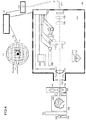
- FIG. 1 is a block diagram of some elements of an apparatus 100 for performing high precision measurements of absolute color and luminance on NEDs, according to some embodiments of the disclosed invention.
- a compact telescope 106 is coupled to a spectroradiometer 104 (for example, CCD detector-based grating spectroradiometer) via a fiberoptic light guide bundle 105 to perform measurements of absolute color and luminance on a NED under test 108.
- the compact telescope 106 includes an entrance pupil of about 5 mm in diameter.
- An image captured by the telescope 106 depicts the precise region of the NED under test 108 that is measured by the spectroradiometer 104.
- An image captured by the telescope 106 provides information on the uniformity of the luminance and uniformity of the color of the NED device under test. Further, an image captured by the telescope provides information on the resolution of the NED device under test.
- the size of the telescope's field stop, and hence, the optics field-of-view can easily be changed in order to vary the size of the region sampled from the device under test (DUT).
- a series of many different area defining measurement apertures can be manually or automatically inserted at the field stop of the telescope system to define FOV sizes of, for example, 5°, 2°, 1°, 0.5°, 0.33° and 0.1°.
- a known aperture wheel or slide mechanism may be included in the focal plane and include a number of apertures of varying sizes, one of which is placed in the light path centered on an axis of the light path.
- a controller circuit and associated circuitry e.g., I/O, memory and logic circuits 102 positions or senses the position of the selected aperture at the selected measurement aperture field of view position.
- the disclosed invention allows the aperture mechanism to be mounted normal to the light path so that any adverse effects due to parts of an aperture being outside the focal plane are avoided.
- the compact telescope 106 also includes an internal video camera view finder (206 in FIG. 2 ) with an image sensor plane (204 in FIG. 2 ) that captures the image of the DUT virtual scene which can be viewed and stored as part of the controller circuit 102.
- the captured image can also be analyzed for uniformity of the DUT virtual image scene as well as the resolution through a depth of contrast measurement or Fourier Transform computation, as part of controller circuit 102.
- the telescope also includes a graphics generator, as part of a controller circuit 102, to display test patterns and color fields on a display device.
- An auto-collimation reference mirror 110 is large enough to cover the distance between the outer edges of the left 114 and right 116 eye pupils of the NED provides a planar mirrored reference surface (PMRS) to establish two parallel optical axes at the right 114 and left eye 116 positions of the NED so that any parallax deviation of the NED can be determined using the integral autocollimator configuration of the telescope 106.
- PMRS planar mirrored reference surface
- a light source 112 for example, a light emitting diode (LED)-based tunable in color and luminance light 112 provides different light levels and different spectral power distributions through the use of multiple LEDs of different wavelengths with individual intensity control for each LED that are mixed in an optical integrating cavity, as known in the art. Consequently, the depth of contrast of the NED can be determined with these simulated real-world background brightness levels with different spectral power distributions to simulate the different ambient backgrounds available in the real world that could be visible through Augmented Reality NEDs.
- LED light emitting diode
- the telescope 106 has four built in modes of operation.
- the first mode allows the operator to align and establish an optical measurement reference axis.
- the second mode allows the operator to view and define the measurement area, the third mode captures an image of the defined measurement area and the complete field of view of the viewfinder digital camera, and the fourth mode acquires a spectroradiometric measurement.
- a single command from the user through the circuit controller 102 initiates both image capture and spectroradiometric measurement modes in rapid succession.
- the controller circuit 102 positions each axis of a mechanical multi-axis (e.g., 6 axis) mounting platform 118 attached to the compact telescope 106. This allows for automatic placement of the compact telescope 106 in different locations relative to the NED under test 108 left eye position 114 or right eye position 116 and pointing direction so different areas of the virtual scene can be aligned with the measurement aperture. In some embodiments, the compact telescope 106 can be moved back and forward.
- a mechanical multi-axis e.g., 6 axis
- FIG. 2 is a block diagram of the optical layout of a compact telescope 106 for performing high precision alignment of the reflex optics 202 optical axis 224 in a viewing mode, according to some embodiments of the disclosed invention.
- the right part of the optical axis is blocked by the position of LED 210 projecting light out through the beamsplitter 208 and the objective lens 218 to serve as a reference for the alignment of the reflex optics 202 optical axis 224 and the surface normal of a Planar Mirror Reference Surface (PMRS) 222 to the surface normal reflectance of the physical display surface in VR NED measurement applications and also AR applications.
- PMRS Planar Mirror Reference Surface
- reflex optics 202 are employed in order establish parallel optical axis for the left and right of the NED that will be imaged by the telescope 106 that includes a sensor plane 204 at its view finder.
- a thin beamsplitter 208 is inserted into the optical path of the telescope. This enables light from an LED lamp 210, which is also positioned behind a selectable measurement area defining, field-of-view (FOV) aperture 212, to project onto the NED and illuminate the precise area that is being viewed by the telescope on a display. This illumination, along with anything displayed on the NED, are then reimaged on to the telescope sensor plane 204.
- the beamsplitter 208 is positioned at 45 degrees to the light path and optical axis 224.
- the beamsplitter 208 may include a transparent polymer films (in some embodiments, 3 to 5 microns thick) supported on a metal frame having one uncoated surface and one reflection coated surface, and aligned to provide light in a path normal to the focal of the sensor plane 204.
- This form of beamsplitter provides approximately 50% of the light in the path to the focal plane, which is adequate for the video viewfinder digital camera 206 image sensor plane 204 to provide an image of the DUT virtual scene to the controller circuit 102.
- the coated surface of the beamsplitter 208 may be facing the objective lens 218.
- the beamsplitter 208 may include a glass plate having one uncoated surface and one antireflection coated surface, and aligned to provide light in a path normal to the sensor plane 204.
- This form of beamsplitter provides approximately 4% of the light in the path to the focal plane, which is adequate for the video viewfinder digital camera 206 image sensor plane 204 to provide an image of the DUT.
- the lamp 210 positioned behind the Field of View aperture 212 projects some percentage of light out through the beamsplitter 208, the objective lens 218 and the entrance pupil 220.
- the remaining percentage of projected light from the lamp 210 reflects off the beamsplitter 208 down toward the collimating lens 214 and retroreflector prism 216.
- This light entering the retroreflector prism 216 passes back through the collimating lens 214 toward the beamsplitter 208.
- a portion of this light passes through the beamsplitter 208 and forms an image 226 of the projected FOV aperture 212 on the image sensor plane 204 of the viewfinder digital camera 206.
- the compact telescope 106 can be moved back and forward on the optical axis 224 to measure any parallax on the DUT.
- the objective lens 218 When the objective lens 218 is set to infinity focus relative to the FOV aperture 212 by setting the distance between the FOV aperture 212 at the focal point of the objective lens 218, the portion of light that passed through the beamsplitter 208 projecting out through the objective lens 218 and entrance pupil 220 to the PMRS 222 is collimated by adjusting the distance between the objective lens 218 and the FOV aperture 212.
- Motion mechanism 234 is able to position the objective lens 218 at different distances from the FOV aperture 212 from control circuit 236 in the compact telescope 106. Controller circuit 102 is also used as part of the positioning process of objective lens 218 relative to the position of the FOV aperture 212.
- the collimated light is reflected off of the PMRS 222.
- the reflected light passes back through the entrance pupil 220, objective lens 218, some portion reflects off of the beamsplitter 208 and when the distance of the objective lens 218 is at its focal distance from the FOV aperture 212, forms the most well defined image 228 of the FOV aperture 212 on the image sensor plane 204 of the viewfinder digital camera 206.
- the image of the projected FOV aperture 226 will be directly superimposed on the image 228 of the FOV aperture 212. Any angular deviation of the surface normal from the optical axis will produce an image 228 of the FOV aperture 212 that is offset from the image position of the FOV Reference Image 226 and the pointing direction of the telescope optical axis 224 can be redirected to the precise alignment direction.
- the pointing direction may be redirected by manual setting of the elevation 230, azimuth 232 mirror angle adjusters and/or the controller circuit 102 positioning the optical axis 224 parallel to the PMRS 222 surface normal with the 6 mechanical axis mounting platform 118 attached to the compact telescope 106.
- the FOV measurement aperture 212 can be interchanged for different diameter or area measurement apertures either with a manual interchange or with motor 238, by control circuits 236 and 102, moving, for example, a wheel or slide mechanism that maintains the center location position on and along the optical axis 224 of each of the different diameter or area FOV measurement aperture 212.
- FIG. 3 is a block diagram of the optical layout of a measurement apparatus in a viewing and image capture mode, according to some embodiments of the disclosed invention.
- reflex optics 202 are employed in order to identify the exact portion of the NED virtual scene 336 that is to be imaged by the telescope objective lens 218, reflect off of the beamsplitter 208 and onto the image sensor plane 204 of viewfinder digital camera 206.
- the sensor plane is connected to a display monitor of the controller 102, which renders an image 340 of the NED virtual scene 336.
- the precise location of the NED virtual scene 336 relative to the FOV measurement aperture 212 needs to be established to know where the measurement sample is relative to the details in the image 336.
- light from an LED lamp 210 which is positioned behind a selectable field-of-view (FOV) aperture 212, projects light out toward the beamsplitter 208 along the optical axis 224.
- This light is reflected from the rear of the beamsplitter 208 through collimating lens 214 to a corner cube retroreflector (or prism) 216 in order to return light defining the image of the aperture 212 to the rear of the beamsplitter.
- At least, 45% of the light is transmitted toward the view finder 206 image sensor plane 204.
- the collimating lens 214 is positioned at the focal length distance from aperture 212. This collimates the light entering corner cube retroreflector 216 which retro-reflects light back through the collimating lens 214.
- At least 45% percent of this retroreflected light passes through the beamsplitter 208 and forms an image 226 of the measurement FOV aperture 212 at the image sensor plane 204 of the viewfinder digital camera 206. Because the same beamsplitter directs both the light from the NED virtual scene 336 to form image 340 and light from the lamp 210 to form image of the aperture 212, the illuminated image 226 of the measurement aperture is superimposed on the image of the DUT virtual scene 340. The operator can know the precise location that the measurement aperture 212 will collect light from the NED virtual scene 336.
- any errors in the angle of the beamsplitter 208 are self-compensating in that if the beamsplitter pivots or moves, the images of the DUT virtual scene 340 and aperture image 226 move together.
- the position of the objective lens 218 may be adjusted using the motion mechanism 234 for focus adjustment 234 to verify that the image 340 of the DUT virtual scene is in sharp focus.
- this functionality also facilitates measurement telescope optical axis 224 alignment to the optical axis 338 of the DUT, as well as the measurement of parallax, between the left 114 and right eye 116 sides of the NED DUT 108.
- a mirror 222(110) with elevation angle adjustment 230 and azimuth angle adjustment 232 which is large enough to cover both the left and right sides of the NED is placed where the virtual scene appears.
- the reflex optics 202 is used as an autocollimator, and the mirror angle is adjusted manually or automatically by adjusting the reflex optics 202 optical axis 224 through the controller circuit 102 with the multi-axis mechanical axis motion apparatus 118, until the beam is returned on itself.
- the mirror 222(110) is perpendicular to the telescope optical axis 224 and provides a virtual object for the telescope (its own projected field stop) which appears to be at infinity (collimated) when the objective lens 218 is positioned with motion mechanism 234 at the objective lens 218 focal distance from the FOV aperture 212.
- the autocollimator shows whether there has been any change in pointing angle by a shift of the position of image 226 of the FOV aperture 212 relative to the position of the image 340 of the NED virtual scene. Also, if the compact telescope 106 is moved a distance corresponding to the separation of the left and right eye displays in the NED, the measurement apparatus can determine the shift in pointing direction (or parallax) of any element that appears in the displays relative to the PMRS 222 surface normal.
- the electrical power to the LED 210 can be switched off (with a switch) by circuit controller 102 connected to control circuit 236 or manually locally at the compact telescope 106 with the control circuit 236 to eliminate the image of the measurement aperture 226 from the image sensor plane 204 of the viewfinder digital camera 206, leaving the image of the DUT virtual scene 340.
- This image 340 of the virtual scene 336 formed on the image sensor 204 of the viewfinder 206 is captured by the controller circuit 102.
- the controller circuit 102 generates test patterns for the DUT so that various image patterns can be analyze for the DUT performance characterization.
- the image sensor 206 includes a CMOS integrated circuit package with an array of 3008 rows and 4112 columns of individual light sensors. When the sensors are exposed to light they produce a charge that is proportional to the light level received.
- the viewfinder digital camera 206 and control circuit 102 collects the charge form each of the individual sensors and produce a tabular array of numerical data with each element of the detector sensor array corresponding to an individual numerical data value.
- the sub section of this tabular array of numerical values can be identified as the area of the virtual image scene also measured by the spectroradiometer after passing through the FOV measurement aperture 212.
- the measured spectroradiometer data over the visible spectral region is stored in control circuit 102 is analyzed by applying, for example, the ISO/CIE 11664-3:2012 Standard Colorimetric Observer weighting functions to the spectroradiometer data.
- the luminance and color within the area of FOV measurement aperture 212 can be determined and the color of the sub section of the image 340 of the DUT virtual scene 336 formed on the image sensor 204 of the viewfinder 206 defined by the image 226 of the FOV measurement aperture 212.
- the luminance and color in the sub area of the image sensor 204 defined by the image 226 is then correlated to the tabular numerical data corresponding to the average of all the individual light sensors in this sub area.
- the quotient between the numerical values outside the sub area and the average in the sub area is computed for each value in the tabular array.
- the tabular array of quotient values over the 3008 rows and 4112 columns of individual light sensor positions when multiplied by the luminance or color values creates a map of the uniformity of or color of the image 340.
- the Modulation Contrast Function (MTF) of the DUT image scene 336 can be measured from the image 340.
- the circuit controller can display different scenes and test patterns on the DUT NED 108.
- a test pattern of vertical lines as the display scene 336 produces and image 340 as other display scenes and produces a tabular array of numerical data corresponding to the luminance over the entire image area of the image sensor 204.
- the resulting numerical tabular values produced in the control circuit 102 is analyzed to determine the Ratio between the low luminance values for the 0 light level columns in the numerical tabular data array divided by the 50% maximum light output luminance values for the 50% light level columns in the numerical tabular data array. This ration is the depth of modulation contrast ratio of the DUT NED for that line pair frequency.
- a similar process can be repeated for 2 lines on, two lines off, three lines on, 3 lines on and so on to create a set of contrast values that when taken together characterize the MTF of the display producing a scene the depth of modulation contrast as a function of the line pair frequency.
- a similar process is repeated but with horizontal lines replacing the vertical lines.
- display performance characteristics such as luminance and color uniformity and resolution can be determined over the complete field of view from the image 340 of the DUT virtual scene 336 captured by the Image sensor plane 204 of the video viewfinder digital camera 206.
- a full software suite of image analysis tools in controller circuit 102 is used to determine metrics such as color uniformity, luminance uniformity, image contrast, MTF and chromatic aberration. These quantities can then be correlated with the subsequent or previous spectroradiometric measurement defined by the area 226 of image sensor 204 pixels. Analysis of the spectroradiometer data yields luminance and color of the light from the NED contained within the telescope FOV.
- FIG. 4 is a block diagram of the optical layout of a measurement apparatus in a measurement mode, according to some embodiments of the disclosed invention.
- the compact telescope 106 and the reflex optics 202 in FIG. 3 are modified by a first motor 402 moving beamsplitter 208 and by a second motor 404 moving LED 210 out of the optical path along the optical axis 224 using the control circuit 236 and the controller 102 so that none of the light passing through FOV aperture 212 is blocked from reaching lens 406 and lens 408.
- the spatial mixer assures that illuminated subareas of the entrance pupil 220 which pass through the objective lens 218 and pass through the FOV measurement 212 aperture provide a uniform illumination of the spectroradiometer input 412 and hence a uniform measurement of radiance of the DUT virtual image 336, for any location of the illuminate sub area of the entrance pupil 220.
- the output from the spatial mixer 410 enters the end of a fiber optic light guide 412, which transfers the light to the spectroradiometer 104.
- the relay lenses 406 and 408 are of sufficient diameter to collect all light passing through any of the selectable FOV measurement field apertures 212 and deliver it to entry surface of the spatial mixer 410.
- An additional function of the relay lenses 406 and 408 is to image the entrance pupil aperture 220 into spatial mixer 410 that spatially decouples the individual fibers in the fiber optic light guide 412 from the entrance pupil 220.
- the spatial mixer 410 is useful especially when the entrance pupil 220 is not uniformly filled by the illumination in the design eye box of the NED DUT.
- FIG. 5 is a process flow for performance characterization of multi configuration near eye displays, according to some embodiments of the disclosed invention.
- the invention determines the position of the virtual image of the field stop relative to the image of the object or virtual image being measured and then performs spectroradiometric measurement on the captured image of the defined measurement area.
- an optical axis of the optics apparatus is aligned with an optical axis of the DUT to establish an optical measurement axis.
- this alignment process includes superimposing a first image of a field-of-view (FOV) aperture reflected from a beamsplitter that is collimated and reflected back onto the beamsplitter onto a second image of the FOV aperture, back illuminated by a lamp, projected onto the DUT and reflected back onto the same beamsplitter.
- FOV field-of-view
- a 7mm diameter or smaller entrance pupil of the optics apparatus is positioned within the design eye box (qualified viewing space) of a near eye display device under test.
- a measurement area is defined on a virtual image of the DUT.
- This defined measurement area viewed in a view finder of for example, a viewfinder digital camera, needs to be the same as that to which the spectroradiometer is responding.
- reflex optics are utilized to identify the exact portion of the NED virtual scene that is to be imaged.
- adjustments to the pointing direction are performed to move the captured image of the defined measurement area and the complete field of view of the view finder to establish alignment of the FOV measurement aperture to the image of the DUT virtual image and selection of the diameter of the FOV measurement aperture from the selection available, for example, by respective motors controlled by the controller circuit 102. Adjustments are made to the position of the objective lens relative to the FOV measurement aperture to obtain a sharp focus of the DUT virtual image. This adjustment establishes the alignment of the FOV measurement aperture to another area within the DUT scene field of view.
- the same beamsplitter directs both the light from the DUT virtual image to form the viewfinder image and light from the lamp to form image of the FOV aperture
- the illuminated image of the FOV aperture is superimposed on the image of the DUT virtual image, if not, then some adjustment needs to be performed as explained above. Accordingly, the user/operator can know the precise location that the FOV measurement aperture will collect light from the NED virtual image and corresponds to a specific area of sensor elements in the viewfinder digital camera image sensor which are at known and stored locations on the image sensor.
- the lamp that is back illuminating the FOV measurement aperture is switched off allowing just the image of the DUT virtual image to be seen by the viewfinder digital camera image sensor.
- an image of the defined measurement area and a complete field of view of the viewfinder digital camera is captured.
- the captured image is stored in a memory of the controller circuit 102 for determination of depth of contrast and resolution and correlation to the spectroradiometric data.
- the (LED) lamp and the beamsplitter are the moved from the optical measurement axis, for example, by respective motors controlled by the controller circuit 102, so that none of the light passing through FOV aperture is blocked from reaching the spectroradiometers.
- the virtual image of the DUT is focused onto a spatial mixer so that illuminated subareas of the entrance pupil provide a uniform illumination of the spectroradiometer input.
- the optical radiation from the spatial mixer is collected onto the spectroradiometers.
- spectroradiometric measurements are performed on the captured image of the defined measurement area to characterize the performance of the DUT, as described above. The spectroradiometric measurements may then be correlated to the rest of the image sensor area of the DUT image captured and stored from the viewfinder digital camera by the controller circuit.
Landscapes
- Physics & Mathematics (AREA)
- General Physics & Mathematics (AREA)
- Spectroscopy & Molecular Physics (AREA)
- Engineering & Computer Science (AREA)
- Optics & Photonics (AREA)
- General Engineering & Computer Science (AREA)
- Theoretical Computer Science (AREA)
- Chemical & Material Sciences (AREA)
- Analytical Chemistry (AREA)
- Signal Processing (AREA)
- Multimedia (AREA)
- Geometry (AREA)
- Human Computer Interaction (AREA)
- Health & Medical Sciences (AREA)
- Biomedical Technology (AREA)
- General Health & Medical Sciences (AREA)
- Spectrometry And Color Measurement (AREA)
- Length Measuring Devices By Optical Means (AREA)
- Studio Devices (AREA)
- Photometry And Measurement Of Optical Pulse Characteristics (AREA)
Claims (9)
- Verfahren zur Leistungscharakterisierung von augennahen Multi-Konfigurations-Displays als Prüfling (Device Under Test, DUT) durch eine optische Vorrichtung, wobei die optische Vorrichtung eine Sucher-Digitalkamera umfasst, wobei das Verfahren Folgendes umfasst:Ausrichten einer optischen Achse der optischen Vorrichtung mit einer optischen Achse des Prüflings (550) zum Einrichten einer optischen Messachse, wobei das Ausrichten Folgendes umfasst: Erstellen eines Referenzbildes einer Sichtfeld-(Field-Of-View, FOV) Messöffnung, die von einer Lampe beleuchtet wird, wobei ein erster Teil eines von der Lampe beleuchteten Lichts von einem Strahlteiler reflektiert, von einer Kollimationslinse kollimiert und auf den Strahlteiler zurückreflektiert wird, und ein Teil des kollimierten Lichts von der Sucher-Digitalkamera als Referenzbild erfasst wird,Erzeugen eines tatsächlichen Bildes der FOV-Messöffnung durch Projizieren eines zweiten Teils des von der Lampe beleuchteten Lichts vom Strahlteiler auf den Prüfling, und Reflektieren des zweiten Teils des Lichts durch einen Spiegel zurück auf den Strahlteiler,Projizieren eines Teils des reflektierten zweiten Teils des Lichts auf die Sucher-Digitalkamera durch den Strahlteiler undErfassen des Teils des reflektierten zweiten Lichtabschnitts durch die Sucher-Digitalkamera, um das tatsächliche Bild der FOV-Messöffnung zu erzeugen,Überlagern des Referenzbildes der FOV-Messöffnung und des tatsächlichen Bildes der FOV-Messöffnung, um die optische Achse der optischen Vorrichtung mit der optischen Achse des Prüflings auszurichten, um die optische Messachse (558) festzulegen;Kollimieren von vom Strahlteiler reflektiertem Licht und Zurückreflektieren zu einem Bildsensor, um ein virtuelles Bild des Prüflings zu erzeugen;Definieren eines Messbereichs auf dem virtuellen Bild des Prüflings (552) und Erfassen eines Bildes des definierten Messbereichs;Durchführen von Anpassungen zum Verschieben des aufgenommenen Bildes des definierten Messbereichs und eines vollständigen Sichtfelds der Sucher-Digitalkamera (554), um die Ausrichtung der FOV-Messöffnung zum virtuellen Bild des Prüflings herzustellen, wobei das aufgenommene Bild des definierten Messbereichs und das gesamte Sichtfeld der Sucher-Digitalkamera beide von dem Strahlteiler reflektiert werden;Ausschalten der Lampe (556), damit nur das virtuelle Bild des Prüflings von der Sucher-Digitalkamera gesehen werden kann;Bewegen der Lampe und des Strahlteilers von der optischen Messachse (560), so dass kein Licht, das durch die FOV-Messöffnung fällt, daran gehindert wird, ein Spektroradiometer zu erreichen;Projizieren des virtuellen Bildes des Prüflings auf die FOV-Messöffnung;Fokussieren eines Bildes einer Eintrittspupille der optischen Vorrichtung auf einen räumlichen Mischer (562);Sammeln des virtuellen Bildes vom räumlichen Mischer auf einem Spektroradiometer (564); undDurchführen spektroradiometrischer Messungen an dem vom Spektroradiometer aufgenommenen Bild des definierten Messbereichs unter Verwendung des vom räumlichen Mischer (566) gesammelten virtuellen Bildes.
- Verfahren nach Anspruch 1, das ferner das Korrelieren der spektroradiometrischen Messungen mit einem entsprechenden Messbereich auf dem virtuellen Bild des Prüflings zur Bestimmung der Luminanz und Farbgleichmäßigkeit umfasst.
- Verfahren nach Anspruch 1, das ferner das Analysieren des virtuellen Bildes des Prüflings auf Gleichmäßigkeit und Auflösung des virtuellen Bildes des Prüflings durch eine Kontrasttiefenmessung oder eine Fourier-Transformationsberechnung umfasst.
- Verfahren nach Anspruch 1, wobei das Überlagern des ersten Bildes der FOV-Messöffnung mit dem zweiten Bild der FOV-Messöffnung durch eine Flachspiegelreferenzfläche (Planar Mirror Reference Surface, PMRS) durchgeführt wird.
- Vorrichtung zur Leistungscharakterisierung von augennahen Multi-Konfigurations-Displays als Prüfling (DUT), die Folgendes umfasst:einen Spiegel (222) mit Höhenwinkeleinstellung und Azimutwinkeleinstellung, die senkrecht zu einer optischen Achse der Vorrichtung positioniert sind;eine Objektivlinse (218) zum Erfassen von Licht von und zum Projizieren von Licht zum Prüfling;eine Lampe (210) zum Projizieren von Licht;einen Strahlteiler (208), der zwischen der Objektivlinse und der Lampe positioniert ist, um das Licht von der Lampe zu reflektieren;eine Kollimations- und Reflexionslinse (214) zum Kollimieren des vom Strahlteiler reflektierten Lichts und zum Zurückreflektieren zu einem Bildsensor mit einem Sucher, um ein virtuelles Bild des Prüflings zu erzeugen;eine Sichtfeldöffnung (FOV) (212), um Licht von der Lampe durch die Objektivlinse auf den Prüfling zu projizieren, wobei die Lampe ein erstes Bild der Sichtfeldöffnung beleuchtet;einen räumlichen Mischer (410) zum räumlichen Entkoppeln einzelner Fasern in einem faseroptischen Lichtleiter, um das virtuelle Bild des Prüflings zu lenken;ein Spektroradiometer zum Empfangen des gerichteten virtuellen Bildes des Prüflings und zum Durchführen spektroradiometrischer Messungen an einem aufgenommenen Bild eines definierten Messbereichs, um die Leistung des Prüflings unter Verwendung des gerichteten virtuellen Bildes aus dem räumlichen Mischer zu charakterisieren; undeine Steuerschaltung (102) zur Charakterisierung der Leistung des Prüflings basierend auf den spektroradiometrischen Messungen, wobei das erste Bild der FOV-Öffnung, das vom Strahlteiler reflektiert, kollimiert und von der kollimierenden und reflektierenden Linse auf den Strahlteiler zurückreflektiert wird, einem zweiten Bild der auf den Prüfling projizierten FOV-Öffnung überlagert wird und durch die Objektivlinse auf den Strahlteiler zurückreflektiert wird, um eine optische Achse der Optikvorrichtung mit einer optischen Achse des Prüflings auszurichten, um eine optische Messachse festzulegen.
- Vorrichtung nach Anspruch 5, wobei die Steuerschaltung die spektroradiometrischen Messungen mit einem entsprechenden Messbereich auf dem virtuellen Prüflingsbild zur Bestimmung der Luminanz und Farbgleichmäßigkeit korreliert.
- Verfahren nach Anspruch 5, das ferner das Analysieren des virtuellen Bildes des Prüflings auf Gleichmäßigkeit und Auflösung des virtuellen Bildes des Prüflings durch eine Kontrasttiefenmessung oder eine Fourier-Transformationsberechnung umfasst.
- Vorrichtung nach Anspruch 5, die ferner einen Bewegungsmechanismus (234) zum Positionieren der Objektivlinse in unterschiedlichen Abständen von der FOV-Öffnung umfasst, wobei die Objektivlinse als Referenz für die Ausrichtung der optischen Achse der Optikvorrichtung mit der optischen Achse des Prüflings dient.
- Vorrichtung nach Anspruch 5, wobei der Spiegel eine Flachspiegelreferenzfläche (PMRS) (222) zum Überlagern eines Bildes einer projizierten FOV-Öffnung auf dem Bild der FOV-Öffnung ist.
Applications Claiming Priority (2)
| Application Number | Priority Date | Filing Date | Title |
|---|---|---|---|
| US201662409804P | 2016-10-18 | 2016-10-18 | |
| PCT/US2017/057267 WO2018075691A1 (en) | 2016-10-18 | 2017-10-18 | Apparatus and method for multi configuration near eye display performance characterization |
Publications (2)
| Publication Number | Publication Date |
|---|---|
| EP3497423A1 EP3497423A1 (de) | 2019-06-19 |
| EP3497423B1 true EP3497423B1 (de) | 2020-12-09 |
Family
ID=60268462
Family Applications (1)
| Application Number | Title | Priority Date | Filing Date |
|---|---|---|---|
| EP17794831.2A Active EP3497423B1 (de) | 2016-10-18 | 2017-10-18 | Vorrichtung und verfahren zur leistungscharakterisierung einer augennahen multikonfigurationsanzeige |
Country Status (4)
| Country | Link |
|---|---|
| US (2) | US10257509B2 (de) |
| EP (1) | EP3497423B1 (de) |
| CA (1) | CA3079507C (de) |
| WO (1) | WO2018075691A1 (de) |
Families Citing this family (26)
| Publication number | Priority date | Publication date | Assignee | Title |
|---|---|---|---|---|
| CN107515466B (zh) * | 2017-08-14 | 2019-11-26 | 华为技术有限公司 | 一种眼球追踪系统和眼球追踪方法 |
| US10817052B1 (en) * | 2018-01-09 | 2020-10-27 | Facebook Technologies, Llc | Eye emulator devices |
| DE102018120006A1 (de) * | 2018-08-16 | 2020-02-20 | Instrument Systems Optische Messtechnik Gmbh | Verfahren und Vorrichtung zur Überwachung eines Spektralradiometers |
| CN108827604A (zh) * | 2018-09-20 | 2018-11-16 | 京东方科技集团股份有限公司 | 一种视场角测量装置和测量方法 |
| CN111487035B (zh) * | 2019-01-25 | 2022-02-01 | 舜宇光学(浙江)研究院有限公司 | 一种用于近眼检测系统的对准方法及其系统 |
| CN111610637B (zh) * | 2019-02-26 | 2025-06-10 | 弗提图德萨沃有限公司 | 一种光学模组中光学平片的装调系统及方法 |
| US11231814B1 (en) * | 2019-10-31 | 2022-01-25 | Apple Inc. | Electronic devices with curved display surfaces |
| US11035731B1 (en) * | 2020-02-25 | 2021-06-15 | Herbert Alvin Wertheim | Multi-purpose survey spectroradiometer which is also used as a transmittance and reflectance spectrometer |
| US11385464B2 (en) * | 2020-04-09 | 2022-07-12 | Nvidia Corporation | Wide angle augmented reality display |
| US11582375B2 (en) | 2020-09-28 | 2023-02-14 | Argo AI, LLC | Enhanced pointing angle validation |
| CN112763186A (zh) * | 2020-11-19 | 2021-05-07 | 塔普翊海(上海)智能科技有限公司 | 一种虚像距测量系统及测量方法 |
| EP4314754A4 (de) | 2021-03-23 | 2025-01-29 | Radiant Vision Systems, LLC | Bildgebungssysteme mit bildgebungssystemen für ar/vr-vorrichtungen und zugehörige systeme, vorrichtungen und verfahren |
| CN113252309B (zh) * | 2021-04-19 | 2024-10-29 | 苏州市计量测试院 | 一种用于近眼显示设备的测试方法、测试装置及存储介质 |
| CN113099097A (zh) * | 2021-05-21 | 2021-07-09 | 珠海广浩捷科技股份有限公司 | 一种摄像头广角aa组装系统 |
| US12117611B2 (en) | 2021-10-20 | 2024-10-15 | Google Llc | System and method of augmenting a head mounted display for vision correction background |
| US20250025040A1 (en) * | 2021-12-08 | 2025-01-23 | The University Of North Carolina At Chapel Hill | Methods, systems, and computer readable media for biometric ocular photometry |
| US20250220154A1 (en) * | 2022-04-19 | 2025-07-03 | Sony Group Corporation | Light projection device and display device |
| CN115683567B (zh) * | 2022-10-12 | 2026-05-05 | 中国航空工业集团公司洛阳电光设备研究所 | 平视显示器视差量化检测装置、检测及调校方法 |
| CN115683575B (zh) * | 2022-11-15 | 2025-06-13 | 中国科学院合肥物质科学研究院 | 一种高精度可调均匀光源装置 |
| CN116007497B (zh) * | 2022-12-29 | 2025-12-12 | 深圳市信濠光电科技股份有限公司 | 一种影像识别对位快速多片测量方法 |
| US12165550B2 (en) * | 2023-04-27 | 2024-12-10 | Qualcomm Incorporated | Reprojection optimization based on contextual brightness |
| DE102023113210B3 (de) | 2023-05-19 | 2024-10-17 | TechnoTeam Holding GmbH | Objektivanordnung, Messvorrichtung und Verfahren zur Vermessung eines Near Eye Displays |
| WO2025034891A1 (en) * | 2023-08-07 | 2025-02-13 | Glass Imaging Inc. | Imaging system with variable aperture |
| CN117030204B (zh) * | 2023-08-14 | 2026-04-14 | 雷鸟创新技术(深圳)有限公司 | 智能眼镜的测试装置 |
| TWI870105B (zh) * | 2023-11-15 | 2025-01-11 | 致茂電子股份有限公司 | 光學量測裝置之校正系統及方法 |
| CN118936839B (zh) * | 2024-07-23 | 2025-09-12 | 武汉精立电子技术有限公司 | Ned设备检测装置及方法 |
Family Cites Families (6)
| Publication number | Priority date | Publication date | Assignee | Title |
|---|---|---|---|---|
| US3813172A (en) | 1972-01-03 | 1974-05-28 | Kollmorgen Corp | Photometric device with a plurality of measuring fields |
| US5684593A (en) * | 1996-04-25 | 1997-11-04 | Hughes Electronics | Easy to align interferometric reference reflectors |
| US7897912B2 (en) * | 2006-05-25 | 2011-03-01 | Photo Research, Inc. | Spectral and luminance measuring device employing array and single-channel detectors in combination |
| JP2012122757A (ja) * | 2010-12-06 | 2012-06-28 | Olympus Corp | 測光装置 |
| DE102011115027A1 (de) * | 2011-10-07 | 2013-04-11 | Polytec Gmbh | Kohärenzrasterinterferometer und Verfahren zur ortsaufgelösten optischen Vermessung der Oberflächengeometrie eines Objekts |
| US10684477B2 (en) * | 2014-09-30 | 2020-06-16 | Omnivision Technologies, Inc. | Near-eye display device and methods with coaxial eye imaging |
-
2017
- 2017-10-18 EP EP17794831.2A patent/EP3497423B1/de active Active
- 2017-10-18 CA CA3079507A patent/CA3079507C/en active Active
- 2017-10-18 US US15/787,631 patent/US10257509B2/en active Active
- 2017-10-18 WO PCT/US2017/057267 patent/WO2018075691A1/en not_active Ceased
-
2019
- 2019-02-08 US US16/271,692 patent/US10972721B2/en active Active
Non-Patent Citations (1)
| Title |
|---|
| None * |
Also Published As
| Publication number | Publication date |
|---|---|
| US20190191151A1 (en) | 2019-06-20 |
| CA3079507A1 (en) | 2018-04-26 |
| US20180109783A1 (en) | 2018-04-19 |
| CA3079507C (en) | 2022-10-18 |
| US10972721B2 (en) | 2021-04-06 |
| EP3497423A1 (de) | 2019-06-19 |
| WO2018075691A1 (en) | 2018-04-26 |
| US10257509B2 (en) | 2019-04-09 |
Similar Documents
| Publication | Publication Date | Title |
|---|---|---|
| US10972721B2 (en) | Apparatus and method for multi configuration near eye display performance characterization | |
| US9213228B2 (en) | Device and method for measuring a camera | |
| CN111766047B (zh) | 一种模拟人眼的激光显示视觉散斑检测装置 | |
| CN101813520B (zh) | 一种二维光谱测量装置 | |
| CN101813517B (zh) | 一种亮度测量装置 | |
| US5231430A (en) | Ophthalmic apparatus | |
| TW200912385A (en) | Optical characteristic measuring apparatus using light reflected from object to be measured and focus adjusting method therefor | |
| US9239237B2 (en) | Optical alignment apparatus and methodology for a video based metrology tool | |
| US12566103B2 (en) | Imaging systems, including imaging systems for AR/VR devices, and associated systems, devices, and methods | |
| JP6784293B2 (ja) | 光学特性測定装置 | |
| KR20250116144A (ko) | 검사 항목에 대한 적어도 하나의 이미지의 이미징 품질을 결정하기 위한 디바이스 및 방법 | |
| US11663937B2 (en) | Pupil tracking in an image display system | |
| CN212410025U (zh) | 一种模拟视觉感知的激光显示散斑测量装置 | |
| Zhang et al. | Color matching criteria in augmented reality | |
| Austin et al. | 65‐3: Spectroradiometric Measurements of Near‐Eye and Head Up Displays | |
| Penczek et al. | 54‐5: Measuring Direct Retinal Projection Displays | |
| US10718949B1 (en) | Display apparatus and method of displaying | |
| HK40008535A (en) | Apparatus and method for multi configuration near eye display performance characterization | |
| HK40008535B (en) | Apparatus and method for multi configuration near eye display performance characterization | |
| US11044460B1 (en) | Polychromatic object imager | |
| US12517004B2 (en) | Reflective periscope for extended-pupil parallelism and virtual imaging distance measurements | |
| KR102222915B1 (ko) | 모듈 전환형 vr 또는 ar 기기 광영상 측정시스템 및 측정방법 | |
| US12188840B1 (en) | Refractive periscope for extended-pupil parallelism and virtual imaging distance measurements | |
| US20240385077A1 (en) | Objective lens arrangement, measuring device and method for measuring of a near eye display | |
| US20240310626A1 (en) | Measurement method and device of near-eye display |
Legal Events
| Date | Code | Title | Description |
|---|---|---|---|
| STAA | Information on the status of an ep patent application or granted ep patent |
Free format text: STATUS: UNKNOWN |
|
| STAA | Information on the status of an ep patent application or granted ep patent |
Free format text: STATUS: THE INTERNATIONAL PUBLICATION HAS BEEN MADE |
|
| PUAI | Public reference made under article 153(3) epc to a published international application that has entered the european phase |
Free format text: ORIGINAL CODE: 0009012 |
|
| STAA | Information on the status of an ep patent application or granted ep patent |
Free format text: STATUS: REQUEST FOR EXAMINATION WAS MADE |
|
| 17P | Request for examination filed |
Effective date: 20190315 |
|
| AK | Designated contracting states |
Kind code of ref document: A1 Designated state(s): AL AT BE BG CH CY CZ DE DK EE ES FI FR GB GR HR HU IE IS IT LI LT LU LV MC MK MT NL NO PL PT RO RS SE SI SK SM TR |
|
| AX | Request for extension of the european patent |
Extension state: BA ME |
|
| DAV | Request for validation of the european patent (deleted) | ||
| DAX | Request for extension of the european patent (deleted) | ||
| STAA | Information on the status of an ep patent application or granted ep patent |
Free format text: STATUS: EXAMINATION IS IN PROGRESS |
|
| 17Q | First examination report despatched |
Effective date: 20200507 |
|
| REG | Reference to a national code |
Ref country code: HK Ref legal event code: DE Ref document number: 40008535 Country of ref document: HK |
|
| REG | Reference to a national code |
Ref country code: DE Ref legal event code: R079 Ref document number: 602017029364 Country of ref document: DE Free format text: PREVIOUS MAIN CLASS: G01M0011000000 Ipc: G01J0003020000 |
|
| GRAP | Despatch of communication of intention to grant a patent |
Free format text: ORIGINAL CODE: EPIDOSNIGR1 |
|
| STAA | Information on the status of an ep patent application or granted ep patent |
Free format text: STATUS: GRANT OF PATENT IS INTENDED |
|
| RIC1 | Information provided on ipc code assigned before grant |
Ipc: G01M 11/04 20060101ALI20200629BHEP Ipc: G01J 3/28 20060101ALI20200629BHEP Ipc: G01J 1/00 20060101ALI20200629BHEP Ipc: G02B 7/00 20060101ALI20200629BHEP Ipc: G02B 27/01 20060101ALI20200629BHEP Ipc: G01M 11/02 20060101ALI20200629BHEP Ipc: G01J 3/50 20060101ALI20200629BHEP Ipc: G06F 3/01 20060101ALI20200629BHEP Ipc: G01J 3/02 20060101AFI20200629BHEP |
|
| INTG | Intention to grant announced |
Effective date: 20200727 |
|
| GRAS | Grant fee paid |
Free format text: ORIGINAL CODE: EPIDOSNIGR3 |
|
| GRAA | (expected) grant |
Free format text: ORIGINAL CODE: 0009210 |
|
| STAA | Information on the status of an ep patent application or granted ep patent |
Free format text: STATUS: THE PATENT HAS BEEN GRANTED |
|
| AK | Designated contracting states |
Kind code of ref document: B1 Designated state(s): AL AT BE BG CH CY CZ DE DK EE ES FI FR GB GR HR HU IE IS IT LI LT LU LV MC MK MT NL NO PL PT RO RS SE SI SK SM TR |
|
| REG | Reference to a national code |
Ref country code: GB Ref legal event code: FG4D |
|
| REG | Reference to a national code |
Ref country code: AT Ref legal event code: REF Ref document number: 1343911 Country of ref document: AT Kind code of ref document: T Effective date: 20201215 Ref country code: CH Ref legal event code: EP |
|
| REG | Reference to a national code |
Ref country code: DE Ref legal event code: R096 Ref document number: 602017029364 Country of ref document: DE |
|
| REG | Reference to a national code |
Ref country code: IE Ref legal event code: FG4D |
|
| PG25 | Lapsed in a contracting state [announced via postgrant information from national office to epo] |
Ref country code: GR Free format text: LAPSE BECAUSE OF FAILURE TO SUBMIT A TRANSLATION OF THE DESCRIPTION OR TO PAY THE FEE WITHIN THE PRESCRIBED TIME-LIMIT Effective date: 20210310 Ref country code: NO Free format text: LAPSE BECAUSE OF FAILURE TO SUBMIT A TRANSLATION OF THE DESCRIPTION OR TO PAY THE FEE WITHIN THE PRESCRIBED TIME-LIMIT Effective date: 20210309 Ref country code: RS Free format text: LAPSE BECAUSE OF FAILURE TO SUBMIT A TRANSLATION OF THE DESCRIPTION OR TO PAY THE FEE WITHIN THE PRESCRIBED TIME-LIMIT Effective date: 20201209 Ref country code: FI Free format text: LAPSE BECAUSE OF FAILURE TO SUBMIT A TRANSLATION OF THE DESCRIPTION OR TO PAY THE FEE WITHIN THE PRESCRIBED TIME-LIMIT Effective date: 20201209 |
|
| REG | Reference to a national code |
Ref country code: AT Ref legal event code: MK05 Ref document number: 1343911 Country of ref document: AT Kind code of ref document: T Effective date: 20201209 |
|
| PG25 | Lapsed in a contracting state [announced via postgrant information from national office to epo] |
Ref country code: BG Free format text: LAPSE BECAUSE OF FAILURE TO SUBMIT A TRANSLATION OF THE DESCRIPTION OR TO PAY THE FEE WITHIN THE PRESCRIBED TIME-LIMIT Effective date: 20210309 Ref country code: SE Free format text: LAPSE BECAUSE OF FAILURE TO SUBMIT A TRANSLATION OF THE DESCRIPTION OR TO PAY THE FEE WITHIN THE PRESCRIBED TIME-LIMIT Effective date: 20201209 Ref country code: LV Free format text: LAPSE BECAUSE OF FAILURE TO SUBMIT A TRANSLATION OF THE DESCRIPTION OR TO PAY THE FEE WITHIN THE PRESCRIBED TIME-LIMIT Effective date: 20201209 |
|
| REG | Reference to a national code |
Ref country code: NL Ref legal event code: MP Effective date: 20201209 |
|
| PG25 | Lapsed in a contracting state [announced via postgrant information from national office to epo] |
Ref country code: HR Free format text: LAPSE BECAUSE OF FAILURE TO SUBMIT A TRANSLATION OF THE DESCRIPTION OR TO PAY THE FEE WITHIN THE PRESCRIBED TIME-LIMIT Effective date: 20201209 Ref country code: NL Free format text: LAPSE BECAUSE OF FAILURE TO SUBMIT A TRANSLATION OF THE DESCRIPTION OR TO PAY THE FEE WITHIN THE PRESCRIBED TIME-LIMIT Effective date: 20201209 |
|
| REG | Reference to a national code |
Ref country code: LT Ref legal event code: MG9D |
|
| PG25 | Lapsed in a contracting state [announced via postgrant information from national office to epo] |
Ref country code: RO Free format text: LAPSE BECAUSE OF FAILURE TO SUBMIT A TRANSLATION OF THE DESCRIPTION OR TO PAY THE FEE WITHIN THE PRESCRIBED TIME-LIMIT Effective date: 20201209 Ref country code: PT Free format text: LAPSE BECAUSE OF FAILURE TO SUBMIT A TRANSLATION OF THE DESCRIPTION OR TO PAY THE FEE WITHIN THE PRESCRIBED TIME-LIMIT Effective date: 20210409 Ref country code: SK Free format text: LAPSE BECAUSE OF FAILURE TO SUBMIT A TRANSLATION OF THE DESCRIPTION OR TO PAY THE FEE WITHIN THE PRESCRIBED TIME-LIMIT Effective date: 20201209 Ref country code: SM Free format text: LAPSE BECAUSE OF FAILURE TO SUBMIT A TRANSLATION OF THE DESCRIPTION OR TO PAY THE FEE WITHIN THE PRESCRIBED TIME-LIMIT Effective date: 20201209 Ref country code: EE Free format text: LAPSE BECAUSE OF FAILURE TO SUBMIT A TRANSLATION OF THE DESCRIPTION OR TO PAY THE FEE WITHIN THE PRESCRIBED TIME-LIMIT Effective date: 20201209 Ref country code: CZ Free format text: LAPSE BECAUSE OF FAILURE TO SUBMIT A TRANSLATION OF THE DESCRIPTION OR TO PAY THE FEE WITHIN THE PRESCRIBED TIME-LIMIT Effective date: 20201209 Ref country code: LT Free format text: LAPSE BECAUSE OF FAILURE TO SUBMIT A TRANSLATION OF THE DESCRIPTION OR TO PAY THE FEE WITHIN THE PRESCRIBED TIME-LIMIT Effective date: 20201209 |
|
| PG25 | Lapsed in a contracting state [announced via postgrant information from national office to epo] |
Ref country code: PL Free format text: LAPSE BECAUSE OF FAILURE TO SUBMIT A TRANSLATION OF THE DESCRIPTION OR TO PAY THE FEE WITHIN THE PRESCRIBED TIME-LIMIT Effective date: 20201209 Ref country code: AT Free format text: LAPSE BECAUSE OF FAILURE TO SUBMIT A TRANSLATION OF THE DESCRIPTION OR TO PAY THE FEE WITHIN THE PRESCRIBED TIME-LIMIT Effective date: 20201209 |
|
| REG | Reference to a national code |
Ref country code: DE Ref legal event code: R097 Ref document number: 602017029364 Country of ref document: DE |
|
| PG25 | Lapsed in a contracting state [announced via postgrant information from national office to epo] |
Ref country code: IS Free format text: LAPSE BECAUSE OF FAILURE TO SUBMIT A TRANSLATION OF THE DESCRIPTION OR TO PAY THE FEE WITHIN THE PRESCRIBED TIME-LIMIT Effective date: 20210409 |
|
| PLBE | No opposition filed within time limit |
Free format text: ORIGINAL CODE: 0009261 |
|
| STAA | Information on the status of an ep patent application or granted ep patent |
Free format text: STATUS: NO OPPOSITION FILED WITHIN TIME LIMIT |
|
| PG25 | Lapsed in a contracting state [announced via postgrant information from national office to epo] |
Ref country code: AL Free format text: LAPSE BECAUSE OF FAILURE TO SUBMIT A TRANSLATION OF THE DESCRIPTION OR TO PAY THE FEE WITHIN THE PRESCRIBED TIME-LIMIT Effective date: 20201209 Ref country code: IT Free format text: LAPSE BECAUSE OF FAILURE TO SUBMIT A TRANSLATION OF THE DESCRIPTION OR TO PAY THE FEE WITHIN THE PRESCRIBED TIME-LIMIT Effective date: 20201209 |
|
| 26N | No opposition filed |
Effective date: 20210910 |
|
| PG25 | Lapsed in a contracting state [announced via postgrant information from national office to epo] |
Ref country code: DK Free format text: LAPSE BECAUSE OF FAILURE TO SUBMIT A TRANSLATION OF THE DESCRIPTION OR TO PAY THE FEE WITHIN THE PRESCRIBED TIME-LIMIT Effective date: 20201209 Ref country code: SI Free format text: LAPSE BECAUSE OF FAILURE TO SUBMIT A TRANSLATION OF THE DESCRIPTION OR TO PAY THE FEE WITHIN THE PRESCRIBED TIME-LIMIT Effective date: 20201209 |
|
| PG25 | Lapsed in a contracting state [announced via postgrant information from national office to epo] |
Ref country code: ES Free format text: LAPSE BECAUSE OF FAILURE TO SUBMIT A TRANSLATION OF THE DESCRIPTION OR TO PAY THE FEE WITHIN THE PRESCRIBED TIME-LIMIT Effective date: 20201209 |
|
| REG | Reference to a national code |
Ref country code: CH Ref legal event code: PL |
|
| PG25 | Lapsed in a contracting state [announced via postgrant information from national office to epo] |
Ref country code: IS Free format text: LAPSE BECAUSE OF FAILURE TO SUBMIT A TRANSLATION OF THE DESCRIPTION OR TO PAY THE FEE WITHIN THE PRESCRIBED TIME-LIMIT Effective date: 20210409 |
|
| REG | Reference to a national code |
Ref country code: BE Ref legal event code: MM Effective date: 20211031 |
|
| PG25 | Lapsed in a contracting state [announced via postgrant information from national office to epo] |
Ref country code: MC Free format text: LAPSE BECAUSE OF FAILURE TO SUBMIT A TRANSLATION OF THE DESCRIPTION OR TO PAY THE FEE WITHIN THE PRESCRIBED TIME-LIMIT Effective date: 20201209 |
|
| PG25 | Lapsed in a contracting state [announced via postgrant information from national office to epo] |
Ref country code: LU Free format text: LAPSE BECAUSE OF NON-PAYMENT OF DUE FEES Effective date: 20211018 Ref country code: BE Free format text: LAPSE BECAUSE OF NON-PAYMENT OF DUE FEES Effective date: 20211031 |
|
| PG25 | Lapsed in a contracting state [announced via postgrant information from national office to epo] |
Ref country code: LI Free format text: LAPSE BECAUSE OF NON-PAYMENT OF DUE FEES Effective date: 20211031 Ref country code: CH Free format text: LAPSE BECAUSE OF NON-PAYMENT OF DUE FEES Effective date: 20211031 |
|
| PG25 | Lapsed in a contracting state [announced via postgrant information from national office to epo] |
Ref country code: IE Free format text: LAPSE BECAUSE OF NON-PAYMENT OF DUE FEES Effective date: 20211018 |
|
| PG25 | Lapsed in a contracting state [announced via postgrant information from national office to epo] |
Ref country code: CY Free format text: LAPSE BECAUSE OF FAILURE TO SUBMIT A TRANSLATION OF THE DESCRIPTION OR TO PAY THE FEE WITHIN THE PRESCRIBED TIME-LIMIT Effective date: 20201209 |
|
| PG25 | Lapsed in a contracting state [announced via postgrant information from national office to epo] |
Ref country code: HU Free format text: LAPSE BECAUSE OF FAILURE TO SUBMIT A TRANSLATION OF THE DESCRIPTION OR TO PAY THE FEE WITHIN THE PRESCRIBED TIME-LIMIT; INVALID AB INITIO Effective date: 20171018 |
|
| PG25 | Lapsed in a contracting state [announced via postgrant information from national office to epo] |
Ref country code: MK Free format text: LAPSE BECAUSE OF FAILURE TO SUBMIT A TRANSLATION OF THE DESCRIPTION OR TO PAY THE FEE WITHIN THE PRESCRIBED TIME-LIMIT Effective date: 20201209 |
|
| PG25 | Lapsed in a contracting state [announced via postgrant information from national office to epo] |
Ref country code: TR Free format text: LAPSE BECAUSE OF FAILURE TO SUBMIT A TRANSLATION OF THE DESCRIPTION OR TO PAY THE FEE WITHIN THE PRESCRIBED TIME-LIMIT Effective date: 20201209 |
|
| PG25 | Lapsed in a contracting state [announced via postgrant information from national office to epo] |
Ref country code: MT Free format text: LAPSE BECAUSE OF FAILURE TO SUBMIT A TRANSLATION OF THE DESCRIPTION OR TO PAY THE FEE WITHIN THE PRESCRIBED TIME-LIMIT Effective date: 20201209 |
|
| PGFP | Annual fee paid to national office [announced via postgrant information from national office to epo] |
Ref country code: DE Payment date: 20251128 Year of fee payment: 9 |
|
| PGFP | Annual fee paid to national office [announced via postgrant information from national office to epo] |
Ref country code: GB Payment date: 20251127 Year of fee payment: 9 |
|
| PGFP | Annual fee paid to national office [announced via postgrant information from national office to epo] |
Ref country code: FR Payment date: 20251125 Year of fee payment: 9 |