EP3498059B1 - Leuchtensteuerung - Google Patents
Leuchtensteuerung Download PDFInfo
- Publication number
- EP3498059B1 EP3498059B1 EP17742771.3A EP17742771A EP3498059B1 EP 3498059 B1 EP3498059 B1 EP 3498059B1 EP 17742771 A EP17742771 A EP 17742771A EP 3498059 B1 EP3498059 B1 EP 3498059B1
- Authority
- EP
- European Patent Office
- Prior art keywords
- input pattern
- user input
- user
- luminaires
- pattern
- Prior art date
- Legal status (The legal status is an assumption and is not a legal conclusion. Google has not performed a legal analysis and makes no representation as to the accuracy of the status listed.)
- Active
Links
Images
Classifications
-
- H—ELECTRICITY
- H05—ELECTRIC TECHNIQUES NOT OTHERWISE PROVIDED FOR
- H05B—ELECTRIC HEATING; ELECTRIC LIGHT SOURCES NOT OTHERWISE PROVIDED FOR; CIRCUIT ARRANGEMENTS FOR ELECTRIC LIGHT SOURCES, IN GENERAL
- H05B47/00—Circuit arrangements for operating light sources in general, i.e. where the type of light source is not relevant
- H05B47/10—Controlling the light source
- H05B47/155—Coordinated control of two or more light sources
-
- H—ELECTRICITY
- H05—ELECTRIC TECHNIQUES NOT OTHERWISE PROVIDED FOR
- H05B—ELECTRIC HEATING; ELECTRIC LIGHT SOURCES NOT OTHERWISE PROVIDED FOR; CIRCUIT ARRANGEMENTS FOR ELECTRIC LIGHT SOURCES, IN GENERAL
- H05B47/00—Circuit arrangements for operating light sources in general, i.e. where the type of light source is not relevant
- H05B47/10—Controlling the light source
- H05B47/175—Controlling the light source by remote control
- H05B47/19—Controlling the light source by remote control via wireless transmission
-
- H—ELECTRICITY
- H05—ELECTRIC TECHNIQUES NOT OTHERWISE PROVIDED FOR
- H05B—ELECTRIC HEATING; ELECTRIC LIGHT SOURCES NOT OTHERWISE PROVIDED FOR; CIRCUIT ARRANGEMENTS FOR ELECTRIC LIGHT SOURCES, IN GENERAL
- H05B47/00—Circuit arrangements for operating light sources in general, i.e. where the type of light source is not relevant
- H05B47/10—Controlling the light source
- H05B47/175—Controlling the light source by remote control
-
- H—ELECTRICITY
- H05—ELECTRIC TECHNIQUES NOT OTHERWISE PROVIDED FOR
- H05B—ELECTRIC HEATING; ELECTRIC LIGHT SOURCES NOT OTHERWISE PROVIDED FOR; CIRCUIT ARRANGEMENTS FOR ELECTRIC LIGHT SOURCES, IN GENERAL
- H05B47/00—Circuit arrangements for operating light sources in general, i.e. where the type of light source is not relevant
- H05B47/10—Controlling the light source
- H05B47/175—Controlling the light source by remote control
- H05B47/196—Controlling the light source by remote control characterised by user interface arrangements
- H05B47/1965—Controlling the light source by remote control characterised by user interface arrangements using handheld communication devices
Definitions
- the present disclosure relates to systems and methods for controlling lighting devices to render a lighting scene in an environment.
- WO2015/150927A1 discloses detecting a touch event at a touch interface of a luminaire. This touch event may be compared to a profile which is related to e.g. a light scene, according to which a luminaire may then be controlled.
- a "connected” device refers to a device - such as a user terminal, or home or office appliance or the like - that is connected to one or more other such devices via a wireless or wired connection in order allow more possibilities for control of the device.
- the device in question is often connected to the one or more other devices as part of a wired or wireless network, such as a Wi-Fi, ZigBee or Bluetooth network.
- the connection may for example allow control of the device from one of the one or more other devices, e.g. from an app (application) running on a user device such as a smart phone, tablet or laptop; and/or may allow for sharing of sensor information or other data between the devices in order to provide more intelligent and/or distributed automated control.
- Lighting systems are part of this movement towards a connected infrastructure.
- Conventional connected lighting systems consist of fixed light sources, which can be controlled through wall-mounted switches, dimmers or more advanced control panels that have pre-programmed settings and effects, or even from an app running on a user terminal such as a smart phone, tablet or laptop. For example, this may allow user to create an ambience using a wide range of colored lighting, dimming options and/or dynamic effects.
- the most common approach is to replace a light switch with a smartphone based app that offers extended control over lighting (for example Philips hue, LIFX, etc.).
- a lighting scene is a particular overall lighting effect in an environment rendered by the light sources in that environment.
- a "sunset" scene may be defined in which the light sources are set to output hues in the red-yellow range of the visible spectrum.
- Each light source may for example output the different hues (or other setting such as saturation or intensity), or a scene may be rendered by all (or some) lights rendering a single color or similar colors.
- lighting scenes may be dynamic in that the output of one or more light source changes over time.
- Control devices for lighting systems range from simple traditional light switches having e.g. only buttons, knobs and/or sliders, to more advanced devices such as smart phones having a graphical user interface (GUI).
- GUI graphical user interface
- these advanced devices provide a greater degree of control of the luminaires.
- existing apps allow a user to set a scene using colors of an image displayed on his user device.
- the present invention recognizes that a user of a lighting system may not always have an advanced control device available to him, or that there can be other circumstances in which using such a device is inconvenient.
- the present invention allows the user to move lighting scenes from one environment to another environment without requiring an advanced control device, such as a smartphone. That is, the user is provided with a degree of control over even complex lighting scenes using simple light switches having a basic user input mechanism - even a single button.
- a method of controlling a lighting system comprising a first plurality of luminaires located in a first environment and a second plurality of luminaires located in a second environment, the method comprising steps of: a first user input pattern at a first light switch of the lighting system, the first light switch being operatively coupled to the first plurality of luminaires; determining at least one parameter of a lighting scene being rendered by the first plurality of luminaires when the first user input pattern is received; storing an indication of the first user input pattern in association with the determined at least one parameter; receiving a second user input pattern at a second light switch of the lighting system, the second light switch being operatively coupled to the second plurality of luminaires; comparing the received second user input pattern with the stored indication of the first user input pattern to determine if the second user input pattern matches the first user input pattern; if the second user input pattern is determined to match the first user input pattern, controlling the second plurality of luminaires to render a matching lighting scene using
- the input pattern can, for example, be as simple as two or more presses of a button of the light switches in quick succession, though more complex patterns and/or switches can be used in other embodiments.
- Connected lighting systems are able to render lighting scenes by receiving lighting instructions over the network (e.g. a ZigBee network) from, for example, a user device such as a smart phone, and interpret the lighting settings in order to determine the appropriate lighting settings for each light source in order that the lighting system renders a desired lighting scene in the environment.
- the network e.g. a ZigBee network
- the environment may be a user's house or home.
- the lighting system may span several "sub-environments" such as the rooms of the house.
- the user of the lighting system may wish to implement a given scene in one room at one point in time and then the same scene in a different room at a later point in time. This behavior is generally called “follow me” behavior.
- “Follow me” behavior implies that the user recalls light settings once, and wherever the user goes in his house, the light settings follow him. For example: the user has a scene based on his favorite holiday picture in the Living Room. When he moves to his Study room the light settings change to match the favorite holiday picture.
- the present invention relates to a simple way to provide the "follow me” behavior to users via manual interaction of the user.
- the manual interaction allows people to have a concept of 'copy-paste' - which is well known in desktop user interfaces - to replicate light settings from one location to the next.
- One particular benefit of the present invention is that the user can in a very intuitive and flexible way re-deploy scenes as he moves around the house, without needing to re-configure the system via an app or without knowing whether that specific scene has been previously configured in the destination room or not.
- the present invention relates to a user-triggered mechanism to move scenes from one location to another. Users can 'encode' a pattern in one room and recall those light settings using the pattern in another room. Switches can then be used to 'copy-paste' light settings between rooms in the lighting system.
- the basic premise of this invention is that a user can assign a coding pattern (also called an input pattern) to light settings in one room. If the user then uses that coding pattern in another room, the lighting system will apply the light settings of the previous room as good as possible.
- a coding pattern also called an input pattern
- a user may have set up the luminaires in one room (e.g. the living room) of his house to be rendering a "sunset" scene, but wishes to move to another room (e.g. the bedroom) where he would like the sunset scene to be rendered.
- one room e.g. the living room
- another room e.g. the bedroom
- the user would have move to the bedroom (and optionally turn off the luminaires in the living room), and then re-deploy the sunset scene (e.g. by taking his smart phone out and selecting the sunset scene and instructing the system to render the scene in the bedroom.
- This may be tedious for the user as it requires in-depth manual re-deployment of the sunset scene once he reaches the bedroom.
- This redeployment may be cumbersome for the user as it requires extra steps such as selecting the same source image for the scene, individually configuring each luminaire to the sunset colors, or saving the scene etc.
- follow me behavior can be implemented by tracking the user's location and deploying the sunset scene dynamically into the user's current room as he moves from the living room to the bedroom.
- the position tracking requires an extensive system of sensors which may be expensive.
- the user can simply input a pattern into the system which is then assigned to the sunset scene within the system, and use this same pattern to redeploy the sunset scene in the bedroom.
- the user might triple-tap on a switch in the living room which causes the system to associate the triple-tap with the sunset scene.
- the triple-tap might also turn off the luminaires in the living room, but this is optional.
- a different pattern such as single tap may be used as an off command, and a triple tap may be used as a "copy" command and wherein the system ignores the "off' functionality.
- a triple-tap of the bedroom switch is all that is need to instruct the system to render the sunset scene in the bedroom.
- the user 309 needs to start a pattern on a single button of a light switch within a specified time interval (e.g., 1 second) for the switch to detect the button events as a pattern. So the first two presses have to happen within the time interval. After that, the user can encode any pattern into the system. There is a timeout of, e.g. 3 seconds: If the user does not press the button 3 seconds after the last press, the pattern is concluded.
- a specified time interval e.g. 1 second
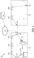
- FIG. 1 shows a system 100 according to embodiments of the present invention.
- a first environment 103 contains a first plurality of luminaires 101a-d and a first switch 105.
- Luminaires 101a-c are ceiling type luminaires designed to provide illumination in the first environment 103 from above.
- Luminaire 101d is a free-standing lamp type luminaire placed on a table designed to provide illumination in the first environment 103 from a lower position than the ceiling type luminaires 101a-c.
- Each of the luminaires 101a-d may be any suitable type of luminaire such as an incandescent light, a fluorescent light, an LED lighting device etc.
- the plurality of luminaires 101a-d may comprise more than one type of luminaire, or each luminaire 101a-d may be of the same type.
- the first switch 105 is shown in Figure 1 as a wall-mounted switch and may be any suitable type of switch allowing user input to control the first plurality of luminaires 101a-d.
- the first switch 105 maybe a simple on-off controller switch or may allow for more complex control such as dimming and possibly even control of individual lighting characteristics such as hue and saturation.
- the first switch 105 is part of the lighting system in that the first switch 105 is able to send data to and receive data from the other elements in the lighting system.
- the first switch 105 is able to access a shared memory of the lighting system (e.g. memory 315, described later).
- a second environment 203 contains a second plurality of luminaires 201a-c and a second switch 205.
- Luminaires 201a-b are ceiling type luminaires designed to provide illumination in the second environment 203 from above.
- Luminaire 201c is wall-washer type luminaire placed on the floor of the second environment 203 and arranged to provide illumination in the second environment 203 by illuminating a wall of the second environment 203.
- each of the luminaires 201a-s maybe any suitable type of luminaire such as an incandescent light, a fluorescent light, an LED lighting device etc.
- the second plurality of luminaires 201a-c may comprise more than one type of luminaire, or each luminaire 201a-c may be of the same type.
- the second switch 205 is shown in Figure 1 as a wall-mounted switch and may be any suitable type of switch allowing user input to control the first plurality of luminaires 201a-d.
- the second switch 205 maybe a simple on-off controller switch or may allow for more complex control such as dimming and possibly even control of individual lighting characteristics such as hue and saturation.
- the second switch 205 is part of the lighting system in that the second switch 205 is able to send data to and receive data from the other elements in the lighting system.
- the second switch 205 is able to access a shared memory of the lighting system (e.g. memory 315, described later).
- the first plurality of luminaires 101a-d, the first switch 105, the second plurality of luminaires 201a-c and the second switch 205 along with a lighting bridge 307 form a connected lighting network. That is, they are all interconnected by wired and/or wireless connections, indicated by dotted lines in Figure 1 .
- Figure 1 shows "chaining" connections such as may be implemented in a ZigBee lighting network, wherein it is not necessary for each device to be directly connected to each other device. Instead, devices are able to relay communication signals which allows for, for example, luminaire 101c to communicate with the lighting bridge 307 by relaying data through luminaires 101b and 101c to lighting bridge 307.
- a "hub-and-spoke" topology may be used in which each device is directly connected (e.g. wirelessly) to the lighting bridge 307 and not to any other devices in the network.
- each luminaire in the network may be configured according to one communication protocol, such as ZigBee, and the switches may be configured according to another communication protocol, such as WiFi.
- the luminaires may communicate with each other and the lighting bridge 307 without relaying data through a switch as shown in Figure 1 , and the switches 105, 205 may communicate directly with the lighting bridge 307.
- the lighting bridge 307 is able to communicate, by whatever appropriate means, with each other device in the lighting network.
- Lighting bridge 307 is arranged at least to receive input (e.g. from switches 105, 205) and to send lighting control commands to luminaires 101a-d, 201a-c.
- Figure 1 also shows a user 309 and user device 311 such as a smart phone.
- the user device 311 is operatively coupled to the lighting bridge 307 by a wired or wireless connection (e.g. WiFi or ZigBee) and hence forms part of the lighting network.
- User 209 can provide user input to the lighting bridge 307 via the user device 311 using, for example, a graphical user interface of the user device 311.
- the lighting bridge 307 interprets the user input and sends control commands to the luminaires 101a-d, 201a-c accordingly.
- the user device 311 generally allows for more complex control than the switches 105, 205.
- the user 309 may use the user device 311 to control an individual luminaire.
- each switch In general it is desirable for each switch to control the luminaires in the same environment as the switch itself, i.e. in Figure 1 switch 105 controls only luminaires 101a-d and switch 205 controls only luminaires 201a-c, but the user device 311 may control any luminaire at all within the lighting network.
- the user 309 may use the user device 311 to control a luminaire in another environment, such as controlling a luminaire in a different room other than the room in which the user 309 and user device 311 are currently.
- This is particularly advantageous because the user device 311 is generally more portable than a switch (particularly a wall-mounted switch), and hence may be used at different physical locations.
- the user device 311 may be used to control the first and/or second plurality of luminaires to render a lighting scene, e.g. by the user 309 selecting the lighting scene and desired luminaires using a GUI of the user device 311.
- lighting bridge 307 may also be provided with a wide area network (WAN) connection such as a connection to the internet 313.
- WAN wide area network
- This connection allows the lighting bridge 307 to connect to external data and services such as memory 315.
- the wireless connection between user device 311 and the lighting bridge 307 is shown in Figure 1 as a direct connection, but it is understood that the user device 311 may also connect to the lighting bridge 307 via the internet 313.
- the first plurality of luminaires 101a-d are rendering a lighting scene.
- User 309 may have controlled the luminaires 101a-d via the lighting bridge 307 using his user device 301 (or by switch 105) to render the lighting scene, or the lighting scene may have been automatically triggered by, for example, detection of the presence of user 309 by a presence sensor (not shown), by a timer, or by an external event or trigger e.g. from a cloud-based server from other services such as a trigger based on local meteorological data.
- the second plurality of luminaires 201a-c may or may not also be rendering a (possibly different) lighting scene.
- the user 309 is able to 'copy-paste' (or 'cut-paste') the lighting scene from the first environment 103 to the second environment 203.
- the user 309 provides a first user input pattern to a controller of the lighting system which then stores the first user input pattern in association with the lighting scene.
- the controller recalls the lighting scene from memory and controls the second plurality of luminaires 201a-c to render the lighting scene in the second environment.
- the lighting scene may initially be set using the user device 311 (for example), but this copy-and-paste functionality of the lighting scene once set is implemented using the light switches 105, 205 alone.
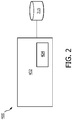
- Figure 2 shows a functional block diagram of a controller 400.
- the controller 400 is a functional block providing the functionality described herein, and the controller 400 may be implemented solely in hardware, software, or in a combination of hardware and software.
- Figure 2 is for the purposes of illustration only.
- Figure 2 shows the controller 400 as comprising code 404 running on at least one processor 402. That is, it is understood that the controller 400 shown in Figure 2 represent a functional block which is implemented in the lighting system 100 shown in Figure 1 .
- the controller 400 may be implemented in the lighting bridge 307, one of the first plurality of luminaires 101a-d, one of the second plurality of luminaires 201a-c, the first switch 105, the second switch 205, or the user device 311.
- the controller 400 may be implemented in a distributed manner with some functionality being implemented in one entity of the lighting system (as mentioned above) and other functionality implemented in one or more other entities of the lighting system.
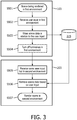
- Figure 3 is a flow diagram of a method implemented by the controller 400 in accordance with embodiments of the present invention. For the purposes of understanding only, Figure 3 shows steps S501-504 as being performed in association with the first environment 103 and steps S505-507 as being performed in association with the second environment 203.
- the method begins at step S501 with a scene being rendered in the first environment 103.
- user input is received at the controller 400 from either the first switch 105.
- the controller 400 is able to determine that the input is in association with the first environment 103, as the controller 400 has been commissioned to know that the first switch 105 is located within, or controls the luminaires of the first environment 103.
- the controller 400 then proceeds, in step S503, to store the scene data as associated with the user input pattern.
- Figure 3 shows the scene data being stored in memory 315 but it is appreciated that this data could be stored in any location or storage means provided that the controller 400 is able to access the stored data at a later time.
- the memory 315 may be a local memory to the controller 400 residing in one or more of the same physical units, or may be an external memory such as an external server accessible over the internet 313.
- the controller 400 may then optionally, as shown in step S504, turn off the first plurality of luminaires.
- the method may be considered a 'cut-and-paste' method, in the sense that the scene is removed from the first environment 103 (before being deployed in the second environment 203). If S504 is omitted, the method may be considered a 'copy-and-paste' method, in the sense that the scene remains in the first environment 103 despite being 'copied' to the second environment 203.
- step S503 of storing the scene to memory 315 is analogous to a computer (usually temporarily) storing a copied item to the 'clipboard' for later use.
- step S505 the user 309 has moved into the second environment 203 and inputted a second input pattern into the system.
- This input may be performed in a similar manner to that described above in relation to step S502, i.e. using a switch.
- the controller 400 determines whether or not there is a scene stored in association with the user input received at step S505. That is, the controller 400 determines whether there is a matching user input stored in memory 315 and, if there is, retrieves the scene data stored in association with that user input pattern from memory 315.
- the controller 400 is able to determine that the second user input (at step S505) is in association with the second environment 203. Hence, the controller 400 is able to determine appropriate luminaires (i.e. the second plurality of luminaires 201a-c) using, e.g. a commissioning data such as the map defining zones mentioned above. The method then proceeds to step S507 wherein the controller 400 controls the second plurality of luminaires 201a-c to render the lighting scene.
- appropriate luminaires i.e. the second plurality of luminaires 201a-c
- the controller 400 determines that there is no stored user input pattern which matches the input pattern received at step S505, there are several options available. This depends on whether the controller 400 is able to distinguish between an input pattern being a first input pattern intended to "copy" a scene, or a second input pattern intended to "paste” a scene. These are discussed in turn below.
- the controller 400 may be able to distinguish these based on current lighting settings in the environment in which the input pattern is received. For example, if the input pattern is received at step S505 in the second environment whilst the luminaires in the second environment are in the "off' state, the controller 400 may determine that the input pattern was intended as a "paste" command.
- the controller 400 may do nothing (i.e. not control any of the luminaires in the system to change their settings), and may wait for a further input to be received, in which case the controller 400 may re-preform step S505 and proceed as described above if the further input matches a stored pattern.
- the controller 400 may control one or more luminaires in the system (e.g. preferably the second plurality of luminaires 201a-c which are visible by the user 209) to signal to the user 309 that the input pattern was not recognized. This may be done by flashing the one or more luminaires, or changing their color.
- the controller 400 may be operatively coupled to another device such as a loudspeaker. In which case, the controller 400 may signal to the user 309 that the input pattern was not recognized by controlling the loudspeaker to emit sound.
- the controller 400 may signal to the user 309 that the input pattern was not recognized by controlling the loudspeaker to emit sound.
- Other examples are readily apparent to one skilled in the art, such as signaling to the user 309 using a display or through his user device 311 using a visible, audible, or tactile signal, or combination thereof.
- the controller 400 may signal to the user 309 using the luminaires and then wait for a further input to be received, in which case the controller 400 may re-preform step S505 and proceed as described above if the further input matches a stored pattern.
- a second timing parameter may be used by the controller 400 as a "lifetime" of a pattern, i.e. a timeout for the pattern to cease to exist (as opposed to the first timing parameter discussed above which is to determine the pattern).
- the only user input pattern described has been either a double-tap or a triple-tap of a button.
- any other pattern may be used provided that the controller 400 is able to distinguish between them.
- the button is be capable of detecting the time between button presses and (possibly) the duration of button presses. This allows the switches to distinguish between short and long taps in a manner analogous to Morse Code.
- a switch may comprise more than one button, in which case the pattern may be a plurality of taps which combined taps of each button in a manner analogous to a keypad door lock.
- the switches are configured to only consider a received pattern if the second tap is input within a predetermined time of the first tap (e.g. 5 seconds).
- the system detects the encoded signal by composing all the button events received in time after each other.
- the system may record only the single tap (*) which may be used to turn the luminaires on/off. This is particularly advantageous as the system maintains traditional light switch behavior wherein the light switch toggles the on state of the luminaires.
- the advanced pattern behavior of the present invention is then still accessible to the user 309 by tapping multiple times within the predetermined time.
- the switches may also be able to determine the duration of a press of a button. This allows users to use short and long presses in the input pattern, so the user can create a truly custom pattern (**-*) or (*---).
- Each pattern can also be associated to different users in the same home, where each has a specific coding that can apply to store and recall scenes in the same rooms without accidentally recalling that of a different user.
- the controller 400 may determine which user has input the pattern by, for example, determining which user's user device is closest to the switch at which the input pattern was received.
- the location of the user device 311 may be determined e.g. using GPS or a plurality of location beacons combined with ToF, RSSI and triangulation, trilateration, multilateration etc. methods. This location may be provided to the controller 40 allowing it to determine that the user device is within a predetermined distance of a given switch.
- the controller 400 can use the locations of user devices A and B to determine which user was most likely to have entered the input pattern. For example, if user device A was one meter away from the first switch 105 at the time the pattern was input, and user device B was twenty meters away, the controller 400 determines that user A input the pattern at the first switch 105. The controller 400 may then store an indication of the pattern along with a lighting scene parameter in association with user A. This is particularly advantageous as it allows users A and B to have a sense of a personal clipboard for storing lighting scenes.
- the controller 400 would only control the second plurality of luminaires 201a-c to render the scene in the second environment if user A entered the matching second pattern (and not user B). Which user entered the second pattern can be determined in a manner similar to described above.
- the system may always store the latest encoded scene into the system. This also allows user to override previous settings.
- the time in which a light scene can be moved to another room can be limited to avoid confusion. For example: after an hour the stored scene is lost and cannot be recalled. Additionally, this may be also limited to specific periods e.g. disabled at night to avoid accidentally waking up someone else.
- the coding patterns need not be fixed over time or per user, as long as the same pattern is used to both store and recall the scene. This means that the mechanism becomes even more flexible as it is not necessary for the user to remember always a specific coding scheme, but just for the transition between rooms.
- a condition can be applied to the system that encoded scenes can only be recalled in other rooms than the one in which they were stored. That means that encoded scenes always have to transfer to another room.
- the detection of a specific recall sequence can take into account the tap encoding, the button used for the encoding, or any combination of these (e.g. double tapping on any button is always the same, or triple tapping must always be done in the same button as used when storing, etc.)
- the devices can detect each other's presence by e.g. beaconing mechanisms
- the user both stores and recalls the scenes using the same input device, where the system can detect via the beaconing mechanism that this device changed room and the coding now applies to the lighting devices in the destination room.
- control devices i.e. the switches
- the control devices do not need to be “wall-mounted”; in fact, they can be portable devices as well.
- the only functionalities they require is that:
- the remote control that is contextually aware (i.e. knows in which room it is in).
- the user can encode a pattern in the first environment (as the remote control knows it is in the first environment, so the scene from the first environment can be identified as the scene to be copied), and then move to the second environment and use the same remote control to "paste" the scene by entering the pattern again on the remote control.
- a portable light switch may be used.
- the portable light switch may be operatively coupled to different sets of luminaires depending on its location. I.e. the operative coupling to luminaires described above can change automatically in response to change in the location of the portable light switch. This may be achieved for example by the portable light switch controlling only luminaires within a given physical radius of itself, or only luminaires within a given communicable range (e.g. a signal range such as line-of-sight).
- controller 400 there is no central device aggregating the data (i.e. controller 400).
- all devices are able to communicate with each other (in different protocols if necessary), such that e.g. when a first pattern is detected in the first control device, it relays that pattern and associated scene to all other relevant devices, such that when the same pattern is detected in a second control device it is not necessary to consult or retrieve information from a central controller.
Landscapes
- Engineering & Computer Science (AREA)
- Computer Networks & Wireless Communication (AREA)
- Circuit Arrangement For Electric Light Sources In General (AREA)
- Selective Calling Equipment (AREA)
Claims (14)
- Verfahren zur Steuerung eines Beleuchtungssystems (100) mit einer in einer ersten Umgebung (103) angeordneten ersten Mehrzahl von Leuchten (101a-d) sowie einer in einer zweiten Umgebung (203) angeordneten zweiten Mehrzahl von Leuchten (201a-c), wobei das Verfahren die folgenden Schritte umfasst, wonach:ein erstes Benutzereingabemuster an einem mit der ersten Mehrzahl von Leuchten betriebsbereit gekoppelten ersten Lichtschalter (105) des Beleuchtungssystems empfangen wird;mindestens ein Parameter einer durch die erste Mehrzahl von Leuchten wiedergegebenen Beleuchtungsszene ermittelt wird, wenn das erste Benutzereingabemuster empfangen wird;eine Angabe des ersten Benutzereingabemusters in Verbindung mit dem ermittelten mindestens einen Parameter gespeichert wird;ein zweites Benutzereingabemuster an einem mit der zweiten Mehrzahl von Leuchten betriebsbereit gekoppelten zweiten Lichtschalter (205) des Beleuchtungssystems empfangen wird;das empfangene zweite Benutzereingabemuster mit der gespeicherten Angabe des ersten Benutzereingabemusters verglichen wird, um zu ermitteln, ob das zweite Benutzereingabemuster mit dem ersten Benutzereingabemuster übereinstimmt;wenn ermittelt wird, dass das zweite Benutzereingabemuster mit dem ersten Benutzereingabemuster übereinstimmt, die zweite Mehrzahl von Leuchten unter Verwendung des mindestens einen Parameters so gesteuert wird, dass eine entsprechende Beleuchtungsszene wiedergegeben wird, die mit der von der ersten Mehrzahl von Leuchten wiedergegebenen Beleuchtungsszene übereinstimmt.
- Verfahren nach Anspruch 1, wobei der erste Lichtschalter ein in der ersten Umgebung montierter fester Lichtschalter ist und der zweite Lichtschalter ein in der zweiten Umgebung montierter fester Lichtschalter ist.
- Verfahren nach einem der vorangegangenen Ansprüche, wobei die Angabe des in Verbindung mit dem ermittelten mindestens einen Parameter gespeicherten ersten Eingabemusters für einen vorgegebenen Zeitraum gespeichert wird und nach Auflauf des vorgegebenen Zeitraums automatisch gelöscht wird.
- Verfahren nach einem der vorangegangenen Ansprüche, wobei die Angabe des ersten Eingabemusters in Verbindung mit einer Kennung eines Benutzers (309) gespeichert wird, der das erste Eingabemuster eingab; eine Kennung eines Benutzers, der das zweite Benutzereingabemuster eingab, mit der gespeicherten Angabe des ersten Benutzereingabemusters verglichen wird, um zu ermitteln, ob der gleiche Benutzer das erste und zweite Eingabemuster eingegeben hat; und wobei die zweite Mehrzahl von Leuchten so gesteuert wird, dass sie die entsprechende Beleuchtungsszene unter der weiteren Voraussetzung wiedergibt, dass ermittelt wird, dass der gleiche Benutzer das erste und zweite Eingabemuster eingegeben hat.
- Verfahren nach einem der vorangegangenen Ansprüche, das weiterhin einen Schritt des Steuerns der ersten Mehrzahl von Leuchten dahingehend umfasst, dass in Reaktion auf den Empfang des ersten Benutereingabemusters ein Ausschalten derselben erfolgt.
- Verfahren nach einem der vorangegangenen Ansprüche, das weiterhin einen Schritt umfasst, wonach, wenn nicht ermittelt wird, dass das zweite Benutzereingabemuster mit dem ersten Benutzereingabemuster übereinstimmt, dem Benutzer eine Angabe zugeführt wird, dass das zweite Benutzereingabemuster nicht mit dem ersten Benutzereingabemuster übereinstimmte.
- Verfahren nach Anspruch 6, wobei diese Angabe dem Benutzer über die zweite Mehrzahl von Leuchten zugeführt wird.
- Verfahren nach Anspruch 6, wobei diese Angabe dem Benutzer über eine Benutzereinrichtung (311) zugeführt wird.
- Verfahren nach einem der vorangegangenen Ansprüche, wobei dieses Benutzereingabemuster zumindest eine erste Betätigung und eine zweite Betätigung einer Taste des Lichtschalters umfasst.
- Verfahren nach Anspruch 9, wobei diese Schritte des Ermitteins und Speicherns bedingungsweise in Reaktion darauf durchgeführt werden, dass die zweite Betätigung innerhalb eines vorgegebenen Zeitraumes der ersten Betätigung empfangen wird.
- Verfahren nach einem der Ansprüche 9 oder 10, das weiterhin beinhaltet, dass eine erste Dauer als eine Dauer der ersten Betätigung und eine zweite Dauer als eine Dauer der zweiten Betätigung ermittelt wird, und wobei dieses Benutzereingabemuster ein Muster von zumindest der ersten Dauer und der zweiten Dauer umfasst.
- Computerprogrammprodukt, das einen auf einem computerlesbaren Speichermedium gespeicherten Code umfasst und so konfiguriert ist, dass es, wenn der Code durch einen Computer ausgeführt wird, den Computer veranlasst, das Verfahren nach einem der vorangegangenen Ansprüche auszuführen.
- Beleuchtungssystem (100), umfassend eine in einer ersten Umgebung (103) angeordnete erste Mehrzahl von Leuchten (101a-d) sowie eine in einer zweiten Umgebung (203) angeordnete zweite Mehrzahl von Leuchten (201a-c), einen oder mehrere Lichtschalter (105, 205), die so konfiguriert sind, dass sie Benutzereingabemuster empfangen, sowie eine Steuereinrichtung (400), wobei die Steuereinrichtung so konfiguriert ist, dass sie die folgenden Schritte ausführt, wonach:ein erstes Benutzereingabemuster detektiert wird, das an einem ersten Lichtschalter empfangen wird, der mit der ersten Mehrzahl von Leuchten betriebsbereit gekoppelt ist;mindestens ein Parameter einer durch die erste Mehrzahl von Leuchten wiedergegebenen Beleuchtungsszene ermittelt wird, wenn das erste Benutzereingabemuster empfangen wird;eine Angabe des ersten Benutzereingabemusters in Verbindung mit dem ermittelten mindestens einen Parameter gespeichert wird;ein zweites Benutzereingabemuster detektiert wird, das an einem zweiten Lichtschalter empfangen wird, der mit der zweiten Mehrzahl von Leuchten betriebsbereit gekoppelt ist;das empfangene zweite Benutzereingabemuster mit der gespeicherten Angabe des ersten Benutzereingabemusters verglichen wird, um zu ermitteln, ob das zweite Benutzereingabemuster mit dem ersten Benutzereingabemuster übereinstimmt;wenn ermittelt wird, dass das zweite Benutzereingabemuster mit dem ersten Benutzereingabemuster übereinstimmt, die zweite Mehrzahl von Leuchten unter Verwendung des mindestens einen Parameters so gesteuert wird, dass eine entsprechende Beleuchtungsszene wiedergegeben wird, die mit der von der ersten Mehrzahl von Leuchten wiedergegebenen Beleuchtungsszene übereinstimmt.
- Beleuchtungssystem nach Anspruch 13, wobei der erste Lichtschalter ein in der ersten Umgebung montierter fester Lichtschalter ist und der zweite Lichtschalter ein in der zweiten Umgebung montierter fester Lichtschalter ist.
Applications Claiming Priority (2)
| Application Number | Priority Date | Filing Date | Title |
|---|---|---|---|
| EP16183556 | 2016-08-10 | ||
| PCT/EP2017/069061 WO2018029010A1 (en) | 2016-08-10 | 2017-07-27 | Lighting control |
Publications (2)
| Publication Number | Publication Date |
|---|---|
| EP3498059A1 EP3498059A1 (de) | 2019-06-19 |
| EP3498059B1 true EP3498059B1 (de) | 2019-12-18 |
Family
ID=56618074
Family Applications (1)
| Application Number | Title | Priority Date | Filing Date |
|---|---|---|---|
| EP17742771.3A Active EP3498059B1 (de) | 2016-08-10 | 2017-07-27 | Leuchtensteuerung |
Country Status (5)
| Country | Link |
|---|---|
| US (1) | US10542611B2 (de) |
| EP (1) | EP3498059B1 (de) |
| JP (1) | JP6584719B1 (de) |
| CN (1) | CN109792821B (de) |
| WO (1) | WO2018029010A1 (de) |
Cited By (1)
| Publication number | Priority date | Publication date | Assignee | Title |
|---|---|---|---|---|
| WO2026061822A1 (en) * | 2024-09-18 | 2026-03-26 | Signify Holding B.V. | Methods and devices for operating a lighting system |
Families Citing this family (8)
| Publication number | Priority date | Publication date | Assignee | Title |
|---|---|---|---|---|
| WO2018028973A1 (en) * | 2016-08-10 | 2018-02-15 | Philips Lighting Holding B.V. | Lighting control |
| WO2020078793A1 (en) * | 2018-10-18 | 2020-04-23 | Signify Holding B.V. | Determining a light effect impact based on a determined input pattern |
| JP6994610B1 (ja) | 2018-12-21 | 2022-01-14 | シグニファイ ホールディング ビー ヴィ | 照明システムを構成するための制御システム及び構成する方法 |
| CN111752443B (zh) * | 2019-03-28 | 2024-07-23 | 华为技术有限公司 | 显示设备控制页面的方法、相关装置及系统 |
| WO2020229207A1 (en) * | 2019-05-15 | 2020-11-19 | Signify Holding B.V. | A controller for controlling a plurality of lighting units of a lighting system and a method thereof |
| CN111586946A (zh) * | 2020-05-28 | 2020-08-25 | 普天智能照明研究院有限公司 | 照明设备的照明方法、系统、装置、存储介质和处理器 |
| EP4275457B1 (de) * | 2021-01-08 | 2024-05-29 | Signify Holding B.V. | Auswahl einer geeigneteren eingabemodalität in bezug auf einen benutzerbefehl zur lichtsteuerung |
| CN114286477A (zh) * | 2021-12-17 | 2022-04-05 | 佛山市顺德区一拓电气有限公司 | 一种基于泳池的灯光控制方法及其系统 |
Family Cites Families (15)
| Publication number | Priority date | Publication date | Assignee | Title |
|---|---|---|---|---|
| US5191265A (en) | 1991-08-09 | 1993-03-02 | Lutron Electronics Co., Inc. | Wall mounted programmable modular control system |
| JP5313153B2 (ja) * | 2006-11-17 | 2013-10-09 | コーニンクレッカ フィリップス エヌ ヴェ | 照明制御のための光ワンド |
| KR101676439B1 (ko) * | 2007-12-04 | 2016-11-15 | 코닌클리케 필립스 엔.브이. | 조명 시스템 및 원격 제어 장치 및 이들의 제어 방법 |
| CN102273323B (zh) * | 2009-01-07 | 2014-09-10 | 皇家飞利浦电子股份有限公司 | 智能的可控照明网络及用于其的大纲 |
| JP2010205421A (ja) | 2009-02-27 | 2010-09-16 | Toshiba Lighting & Technology Corp | 照明制御システム |
| CN102461336B (zh) | 2009-06-05 | 2015-04-22 | 皇家飞利浦电子股份有限公司 | 照明控制设备 |
| PL2543181T3 (pl) * | 2010-03-03 | 2016-03-31 | Koninklijke Philips Nv | Urządzenia i sposoby definiowania systemu kolorów |
| US8890435B2 (en) | 2011-03-11 | 2014-11-18 | Ilumi Solutions, Inc. | Wireless lighting control system |
| US9795004B2 (en) * | 2014-04-14 | 2017-10-17 | Abl Ip Holding Llc | Learning capable lighting equipment |
| JP6456387B2 (ja) * | 2013-08-23 | 2019-01-23 | フィリップス ライティング ホールディング ビー ヴィ | 照明システムの制御 |
| US10299353B2 (en) | 2014-04-02 | 2019-05-21 | Signify Holding B.V. | Methods for initiating state machines in response to touch events detected at home appliances |
| RU2707874C2 (ru) * | 2014-11-25 | 2019-12-02 | Филипс Лайтинг Холдинг Б.В. | Управление освещением на основе близости |
| EP3375260B8 (de) * | 2015-11-11 | 2019-04-10 | Signify Holding B.V. | Erzeugung einer beleuchtungsszenerie |
| JP6418710B2 (ja) * | 2015-12-11 | 2018-11-07 | 株式会社遠藤照明 | 照明システム、設定装置、照明制御方法、及び、照明制御プログラム |
| US9955555B2 (en) * | 2016-04-11 | 2018-04-24 | Noon Home, Inc. | Intelligent lighting control multi-switch apparatuses, systems, and methods |
-
2017
- 2017-07-27 EP EP17742771.3A patent/EP3498059B1/de active Active
- 2017-07-27 CN CN201780049366.XA patent/CN109792821B/zh active Active
- 2017-07-27 WO PCT/EP2017/069061 patent/WO2018029010A1/en not_active Ceased
- 2017-07-27 US US16/324,664 patent/US10542611B2/en active Active
- 2017-07-27 JP JP2019507220A patent/JP6584719B1/ja active Active
Non-Patent Citations (1)
| Title |
|---|
| None * |
Cited By (1)
| Publication number | Priority date | Publication date | Assignee | Title |
|---|---|---|---|---|
| WO2026061822A1 (en) * | 2024-09-18 | 2026-03-26 | Signify Holding B.V. | Methods and devices for operating a lighting system |
Also Published As
| Publication number | Publication date |
|---|---|
| US10542611B2 (en) | 2020-01-21 |
| CN109792821B (zh) | 2021-12-07 |
| US20190174606A1 (en) | 2019-06-06 |
| JP2019532458A (ja) | 2019-11-07 |
| JP6584719B1 (ja) | 2019-10-02 |
| EP3498059A1 (de) | 2019-06-19 |
| WO2018029010A1 (en) | 2018-02-15 |
| CN109792821A (zh) | 2019-05-21 |
Similar Documents
| Publication | Publication Date | Title |
|---|---|---|
| EP3498059B1 (de) | Leuchtensteuerung | |
| CN109792822B (zh) | 照明控制的方法和系统 | |
| TWI611379B (zh) | 遙控燈具方法 | |
| JP6725900B2 (ja) | 照明制御 | |
| EP3516931B1 (de) | Leuchtensteuerung | |
| CN107926099B (zh) | 用于配置照明系统中的设备的方法 | |
| CN109315051B (zh) | 可配置照明系统和方法 | |
| EP3424277B1 (de) | Beleuchtungsszenenauswahl basierend auf dem betrieb einer oder mehrerer einzelner lichtquellen | |
| US10701781B2 (en) | Programming rules for controlling lighting based on user interactions with one or more actuators in one or more zones | |
| EP3498060B1 (de) | Leuchtensteuerung | |
| JP6541893B2 (ja) | 1つ以上の個々の光源の操作に基づく照明シーン選択 | |
| JP2025062113A (ja) | 照明操作機器及び照明システム |
Legal Events
| Date | Code | Title | Description |
|---|---|---|---|
| STAA | Information on the status of an ep patent application or granted ep patent |
Free format text: STATUS: UNKNOWN |
|
| STAA | Information on the status of an ep patent application or granted ep patent |
Free format text: STATUS: THE INTERNATIONAL PUBLICATION HAS BEEN MADE |
|
| PUAI | Public reference made under article 153(3) epc to a published international application that has entered the european phase |
Free format text: ORIGINAL CODE: 0009012 |
|
| STAA | Information on the status of an ep patent application or granted ep patent |
Free format text: STATUS: REQUEST FOR EXAMINATION WAS MADE |
|
| 17P | Request for examination filed |
Effective date: 20190311 |
|
| AK | Designated contracting states |
Kind code of ref document: A1 Designated state(s): AL AT BE BG CH CY CZ DE DK EE ES FI FR GB GR HR HU IE IS IT LI LT LU LV MC MK MT NL NO PL PT RO RS SE SI SK SM TR |
|
| AX | Request for extension of the european patent |
Extension state: BA ME |
|
| GRAP | Despatch of communication of intention to grant a patent |
Free format text: ORIGINAL CODE: EPIDOSNIGR1 |
|
| STAA | Information on the status of an ep patent application or granted ep patent |
Free format text: STATUS: GRANT OF PATENT IS INTENDED |
|
| DAV | Request for validation of the european patent (deleted) | ||
| DAX | Request for extension of the european patent (deleted) | ||
| INTG | Intention to grant announced |
Effective date: 20190715 |
|
| RIN1 | Information on inventor provided before grant (corrected) |
Inventor name: KRAJNC, HUGO JOSE Inventor name: MAGIELSE, REMCO |
|
| GRAS | Grant fee paid |
Free format text: ORIGINAL CODE: EPIDOSNIGR3 |
|
| GRAA | (expected) grant |
Free format text: ORIGINAL CODE: 0009210 |
|
| STAA | Information on the status of an ep patent application or granted ep patent |
Free format text: STATUS: THE PATENT HAS BEEN GRANTED |
|
| AK | Designated contracting states |
Kind code of ref document: B1 Designated state(s): AL AT BE BG CH CY CZ DE DK EE ES FI FR GB GR HR HU IE IS IT LI LT LU LV MC MK MT NL NO PL PT RO RS SE SI SK SM TR |
|
| REG | Reference to a national code |
Ref country code: CH Ref legal event code: EP |
|
| REG | Reference to a national code |
Ref country code: IE Ref legal event code: FG4D |
|
| REG | Reference to a national code |
Ref country code: DE Ref legal event code: R096 Ref document number: 602017009931 Country of ref document: DE |
|
| REG | Reference to a national code |
Ref country code: AT Ref legal event code: REF Ref document number: 1216055 Country of ref document: AT Kind code of ref document: T Effective date: 20200115 |
|
| REG | Reference to a national code |
Ref country code: NL Ref legal event code: MP Effective date: 20191218 |
|
| PG25 | Lapsed in a contracting state [announced via postgrant information from national office to epo] |
Ref country code: LT Free format text: LAPSE BECAUSE OF FAILURE TO SUBMIT A TRANSLATION OF THE DESCRIPTION OR TO PAY THE FEE WITHIN THE PRESCRIBED TIME-LIMIT Effective date: 20191218 Ref country code: GR Free format text: LAPSE BECAUSE OF FAILURE TO SUBMIT A TRANSLATION OF THE DESCRIPTION OR TO PAY THE FEE WITHIN THE PRESCRIBED TIME-LIMIT Effective date: 20200319 Ref country code: NO Free format text: LAPSE BECAUSE OF FAILURE TO SUBMIT A TRANSLATION OF THE DESCRIPTION OR TO PAY THE FEE WITHIN THE PRESCRIBED TIME-LIMIT Effective date: 20200318 Ref country code: FI Free format text: LAPSE BECAUSE OF FAILURE TO SUBMIT A TRANSLATION OF THE DESCRIPTION OR TO PAY THE FEE WITHIN THE PRESCRIBED TIME-LIMIT Effective date: 20191218 Ref country code: LV Free format text: LAPSE BECAUSE OF FAILURE TO SUBMIT A TRANSLATION OF THE DESCRIPTION OR TO PAY THE FEE WITHIN THE PRESCRIBED TIME-LIMIT Effective date: 20191218 Ref country code: SE Free format text: LAPSE BECAUSE OF FAILURE TO SUBMIT A TRANSLATION OF THE DESCRIPTION OR TO PAY THE FEE WITHIN THE PRESCRIBED TIME-LIMIT Effective date: 20191218 Ref country code: BG Free format text: LAPSE BECAUSE OF FAILURE TO SUBMIT A TRANSLATION OF THE DESCRIPTION OR TO PAY THE FEE WITHIN THE PRESCRIBED TIME-LIMIT Effective date: 20200318 |
|
| REG | Reference to a national code |
Ref country code: LT Ref legal event code: MG4D |
|
| PG25 | Lapsed in a contracting state [announced via postgrant information from national office to epo] |
Ref country code: HR Free format text: LAPSE BECAUSE OF FAILURE TO SUBMIT A TRANSLATION OF THE DESCRIPTION OR TO PAY THE FEE WITHIN THE PRESCRIBED TIME-LIMIT Effective date: 20191218 Ref country code: RS Free format text: LAPSE BECAUSE OF FAILURE TO SUBMIT A TRANSLATION OF THE DESCRIPTION OR TO PAY THE FEE WITHIN THE PRESCRIBED TIME-LIMIT Effective date: 20191218 |
|
| PG25 | Lapsed in a contracting state [announced via postgrant information from national office to epo] |
Ref country code: AL Free format text: LAPSE BECAUSE OF FAILURE TO SUBMIT A TRANSLATION OF THE DESCRIPTION OR TO PAY THE FEE WITHIN THE PRESCRIBED TIME-LIMIT Effective date: 20191218 |
|
| PG25 | Lapsed in a contracting state [announced via postgrant information from national office to epo] |
Ref country code: PT Free format text: LAPSE BECAUSE OF FAILURE TO SUBMIT A TRANSLATION OF THE DESCRIPTION OR TO PAY THE FEE WITHIN THE PRESCRIBED TIME-LIMIT Effective date: 20200513 Ref country code: RO Free format text: LAPSE BECAUSE OF FAILURE TO SUBMIT A TRANSLATION OF THE DESCRIPTION OR TO PAY THE FEE WITHIN THE PRESCRIBED TIME-LIMIT Effective date: 20191218 Ref country code: NL Free format text: LAPSE BECAUSE OF FAILURE TO SUBMIT A TRANSLATION OF THE DESCRIPTION OR TO PAY THE FEE WITHIN THE PRESCRIBED TIME-LIMIT Effective date: 20191218 Ref country code: CZ Free format text: LAPSE BECAUSE OF FAILURE TO SUBMIT A TRANSLATION OF THE DESCRIPTION OR TO PAY THE FEE WITHIN THE PRESCRIBED TIME-LIMIT Effective date: 20191218 Ref country code: EE Free format text: LAPSE BECAUSE OF FAILURE TO SUBMIT A TRANSLATION OF THE DESCRIPTION OR TO PAY THE FEE WITHIN THE PRESCRIBED TIME-LIMIT Effective date: 20191218 |
|
| PG25 | Lapsed in a contracting state [announced via postgrant information from national office to epo] |
Ref country code: SM Free format text: LAPSE BECAUSE OF FAILURE TO SUBMIT A TRANSLATION OF THE DESCRIPTION OR TO PAY THE FEE WITHIN THE PRESCRIBED TIME-LIMIT Effective date: 20191218 Ref country code: IS Free format text: LAPSE BECAUSE OF FAILURE TO SUBMIT A TRANSLATION OF THE DESCRIPTION OR TO PAY THE FEE WITHIN THE PRESCRIBED TIME-LIMIT Effective date: 20200418 Ref country code: SK Free format text: LAPSE BECAUSE OF FAILURE TO SUBMIT A TRANSLATION OF THE DESCRIPTION OR TO PAY THE FEE WITHIN THE PRESCRIBED TIME-LIMIT Effective date: 20191218 |
|
| REG | Reference to a national code |
Ref country code: DE Ref legal event code: R097 Ref document number: 602017009931 Country of ref document: DE |
|
| REG | Reference to a national code |
Ref country code: AT Ref legal event code: MK05 Ref document number: 1216055 Country of ref document: AT Kind code of ref document: T Effective date: 20191218 |
|
| PLBE | No opposition filed within time limit |
Free format text: ORIGINAL CODE: 0009261 |
|
| STAA | Information on the status of an ep patent application or granted ep patent |
Free format text: STATUS: NO OPPOSITION FILED WITHIN TIME LIMIT |
|
| PG25 | Lapsed in a contracting state [announced via postgrant information from national office to epo] |
Ref country code: DK Free format text: LAPSE BECAUSE OF FAILURE TO SUBMIT A TRANSLATION OF THE DESCRIPTION OR TO PAY THE FEE WITHIN THE PRESCRIBED TIME-LIMIT Effective date: 20191218 Ref country code: ES Free format text: LAPSE BECAUSE OF FAILURE TO SUBMIT A TRANSLATION OF THE DESCRIPTION OR TO PAY THE FEE WITHIN THE PRESCRIBED TIME-LIMIT Effective date: 20191218 |
|
| 26N | No opposition filed |
Effective date: 20200921 |
|
| PG25 | Lapsed in a contracting state [announced via postgrant information from national office to epo] |
Ref country code: AT Free format text: LAPSE BECAUSE OF FAILURE TO SUBMIT A TRANSLATION OF THE DESCRIPTION OR TO PAY THE FEE WITHIN THE PRESCRIBED TIME-LIMIT Effective date: 20191218 |
|
| PG25 | Lapsed in a contracting state [announced via postgrant information from national office to epo] |
Ref country code: IT Free format text: LAPSE BECAUSE OF FAILURE TO SUBMIT A TRANSLATION OF THE DESCRIPTION OR TO PAY THE FEE WITHIN THE PRESCRIBED TIME-LIMIT Effective date: 20191218 |
|
| PG25 | Lapsed in a contracting state [announced via postgrant information from national office to epo] |
Ref country code: PL Free format text: LAPSE BECAUSE OF FAILURE TO SUBMIT A TRANSLATION OF THE DESCRIPTION OR TO PAY THE FEE WITHIN THE PRESCRIBED TIME-LIMIT Effective date: 20191218 Ref country code: MC Free format text: LAPSE BECAUSE OF FAILURE TO SUBMIT A TRANSLATION OF THE DESCRIPTION OR TO PAY THE FEE WITHIN THE PRESCRIBED TIME-LIMIT Effective date: 20191218 |
|
| REG | Reference to a national code |
Ref country code: CH Ref legal event code: PL |
|
| REG | Reference to a national code |
Ref country code: BE Ref legal event code: MM Effective date: 20200731 |
|
| PG25 | Lapsed in a contracting state [announced via postgrant information from national office to epo] |
Ref country code: CH Free format text: LAPSE BECAUSE OF NON-PAYMENT OF DUE FEES Effective date: 20200731 Ref country code: LI Free format text: LAPSE BECAUSE OF NON-PAYMENT OF DUE FEES Effective date: 20200731 Ref country code: LU Free format text: LAPSE BECAUSE OF NON-PAYMENT OF DUE FEES Effective date: 20200727 |
|
| PG25 | Lapsed in a contracting state [announced via postgrant information from national office to epo] |
Ref country code: BE Free format text: LAPSE BECAUSE OF NON-PAYMENT OF DUE FEES Effective date: 20200731 |
|
| PG25 | Lapsed in a contracting state [announced via postgrant information from national office to epo] |
Ref country code: IE Free format text: LAPSE BECAUSE OF NON-PAYMENT OF DUE FEES Effective date: 20200727 |
|
| PG25 | Lapsed in a contracting state [announced via postgrant information from national office to epo] |
Ref country code: TR Free format text: LAPSE BECAUSE OF FAILURE TO SUBMIT A TRANSLATION OF THE DESCRIPTION OR TO PAY THE FEE WITHIN THE PRESCRIBED TIME-LIMIT Effective date: 20191218 Ref country code: MT Free format text: LAPSE BECAUSE OF FAILURE TO SUBMIT A TRANSLATION OF THE DESCRIPTION OR TO PAY THE FEE WITHIN THE PRESCRIBED TIME-LIMIT Effective date: 20191218 Ref country code: CY Free format text: LAPSE BECAUSE OF FAILURE TO SUBMIT A TRANSLATION OF THE DESCRIPTION OR TO PAY THE FEE WITHIN THE PRESCRIBED TIME-LIMIT Effective date: 20191218 |
|
| PG25 | Lapsed in a contracting state [announced via postgrant information from national office to epo] |
Ref country code: MK Free format text: LAPSE BECAUSE OF FAILURE TO SUBMIT A TRANSLATION OF THE DESCRIPTION OR TO PAY THE FEE WITHIN THE PRESCRIBED TIME-LIMIT Effective date: 20191218 |
|
| P01 | Opt-out of the competence of the unified patent court (upc) registered |
Effective date: 20230425 |
|
| PG25 | Lapsed in a contracting state [announced via postgrant information from national office to epo] |
Ref country code: SI Free format text: LAPSE BECAUSE OF FAILURE TO SUBMIT A TRANSLATION OF THE DESCRIPTION OR TO PAY THE FEE WITHIN THE PRESCRIBED TIME-LIMIT Effective date: 20191218 |
|
| PGFP | Annual fee paid to national office [announced via postgrant information from national office to epo] |
Ref country code: DE Payment date: 20250926 Year of fee payment: 9 |
|
| PGFP | Annual fee paid to national office [announced via postgrant information from national office to epo] |
Ref country code: GB Payment date: 20250722 Year of fee payment: 9 |
|
| PGFP | Annual fee paid to national office [announced via postgrant information from national office to epo] |
Ref country code: FR Payment date: 20250725 Year of fee payment: 9 |