EP3498080A1 - Ramasseuse-hacheuse - Google Patents
Ramasseuse-hacheuse Download PDFInfo
- Publication number
- EP3498080A1 EP3498080A1 EP18200321.0A EP18200321A EP3498080A1 EP 3498080 A1 EP3498080 A1 EP 3498080A1 EP 18200321 A EP18200321 A EP 18200321A EP 3498080 A1 EP3498080 A1 EP 3498080A1
- Authority
- EP
- European Patent Office
- Prior art keywords
- drum
- chopper
- blade
- cutting
- chopping
- Prior art date
- Legal status (The legal status is an assumption and is not a legal conclusion. Google has not performed a legal analysis and makes no representation as to the accuracy of the status listed.)
- Granted
Links
Images


Classifications
-
- A—HUMAN NECESSITIES
- A01—AGRICULTURE; FORESTRY; ANIMAL HUSBANDRY; HUNTING; TRAPPING; FISHING
- A01F—PROCESSING OF HARVESTED PRODUCE; HAY OR STRAW PRESSES; DEVICES FOR STORING AGRICULTURAL OR HORTICULTURAL PRODUCE
- A01F29/00—Cutting apparatus specially adapted for cutting hay, straw or the like
- A01F29/09—Details
- A01F29/22—Arrangement of knife sharpening devices
-
- A—HUMAN NECESSITIES
- A01—AGRICULTURE; FORESTRY; ANIMAL HUSBANDRY; HUNTING; TRAPPING; FISHING
- A01D—HARVESTING; MOWING
- A01D43/00—Mowers combined with apparatus performing additional operations while mowing
- A01D43/08—Mowers combined with apparatus performing additional operations while mowing with means for cutting up the mown crop, e.g. forage harvesters
- A01D43/085—Control or measuring arrangements specially adapted therefor
-
- A—HUMAN NECESSITIES
- A01—AGRICULTURE; FORESTRY; ANIMAL HUSBANDRY; HUNTING; TRAPPING; FISHING
- A01F—PROCESSING OF HARVESTED PRODUCE; HAY OR STRAW PRESSES; DEVICES FOR STORING AGRICULTURAL OR HORTICULTURAL PRODUCE
- A01F29/00—Cutting apparatus specially adapted for cutting hay, straw or the like
- A01F29/06—Cutting apparatus specially adapted for cutting hay, straw or the like having rotating knives with their cutting edges on a cylinder surface, e.g. of the helical-type
-
- A—HUMAN NECESSITIES
- A01—AGRICULTURE; FORESTRY; ANIMAL HUSBANDRY; HUNTING; TRAPPING; FISHING
- A01F—PROCESSING OF HARVESTED PRODUCE; HAY OR STRAW PRESSES; DEVICES FOR STORING AGRICULTURAL OR HORTICULTURAL PRODUCE
- A01F29/00—Cutting apparatus specially adapted for cutting hay, straw or the like
- A01F29/09—Details
- A01F29/095—Mounting or adjusting of knives
-
- G—PHYSICS
- G01—MEASURING; TESTING
- G01B—MEASURING LENGTH, THICKNESS OR SIMILAR LINEAR DIMENSIONS; MEASURING ANGLES; MEASURING AREAS; MEASURING IRREGULARITIES OF SURFACES OR CONTOURS
- G01B7/00—Measuring arrangements characterised by the use of electric or magnetic techniques
- G01B7/28—Measuring arrangements characterised by the use of electric or magnetic techniques for measuring contours or curvatures
- G01B7/293—Measuring arrangements characterised by the use of electric or magnetic techniques for measuring contours or curvatures for measuring radius of curvature
Definitions
- the present invention relates to a forage harvester comprising a cutting edge detection device for detecting a cutting severity of a chopping plant for comminuting a Erntegutstroms according to the preamble of claim 1.
- the forage harvester in question is equipped with a chopper, which has a knife drum with arranged thereon, elongated chopping knives and a stationary counter-blade.
- the harvested crop fed to the chopper drum is shredded by the interaction between the chopper knives and the counterknife, that is, crushed.
- the chopping plant is subject to wear due to wear of the chopping blades.
- there is a wear-related removal in the area of the cutting edges of the chopper blades which leads to a reduction of cut quality and Erntegut malficient.
- the known cutting sharpness detection device for detecting a cutting severity of a chaff ( DE 10 2014 218 408 A1 ), from which the invention proceeds, is based on the fundamental consideration that the engagement gap between chopper blade and counter-blade can form a gap of a magnetic circuit, so that from the change in the magnetic flux can be concluded on the cutting severity of the respective cutterhead.
- the cutting sharpness detection device is equipped with a magnet arrangement.
- the magnet assembly As the magnet assembly passes through a chopper blade, the magnet assembly generates a magnetic flux that penetrates the chopper blade across its length.
- the resulting magnetic flux depends i.a. from the cutting severity of the respective cutterhead, so that it can be inferred in principle on the Schneid2020rfegrad.
- the known cutting sharpness detection device is disadvantageous insofar as the detection of the cutting severity only affects a single measuring point along the longitudinal extent of the chopping blade concerned. This can lead to a misjudgment of the cutting severity, for example if a singular defect of the chopper knife is present at this measuring point, but the chopper knife is otherwise wear-free. In order to avoid such a misjudgment, several of the known cutting-edge detection devices would have to be arranged along the chopping blades passing through the magnet arrangement. This would be technically disadvantageous.
- the invention is based on the problem, the known forage harvester with cutting edge detection device to design and further develop that the detection of the cutting severity of the shredder is improved with simple measures.
- the cutting sharpness detection device has a magnet arrangement which generates a magnetic flux as soon as one of the cutter blades of the cutterhead passes the magnet arrangement.
- the magnet arrangement Upon rotation of the cutterhead, at least a portion of the chopper blades passes the magnet assembly cyclically.
- a magnetic circuit which is excited by the magnet arrangement is closed. The magnetic flux resulting in this magnetic circuit depends on the cutting severity of the respective cutter.
- the cutting-sharpness detection device detects the magnetic flux in the respective magnetic circuit and determines therefrom the cutting-sharpness.
- the cutting severity results from the wear-related removal of the cutting edge of the respective chopper blade and the associated increase in the width of the gap between the cutting edge of the chopper blade and the magnet assembly.
- a magnetic measurement characterizing the magnetic flux changes accordingly, for example, the field strength in the respective magnetic circuit decreases accordingly.
- Essential for the proposed solution is the fundamental consideration that at least part of the magnetic flux of the magnetic circuit closed by the respective chopper blade is guided longitudinally in the chopper blade over at least a longitudinal section of the respective chopper blade. Unlike the known from the prior art, the magnetic flux in the respective chopping knife is therefore no longer transversely guided, but longitudinally guided. The determination of a decrease in the cutting severity by the cutting sharpness detection device thus affects the entire above-mentioned respective longitudinal section of the chopper blade, so that a singular flaw referred to above in the determination of the cutting severity level is less significant.
- the Materialzuström Symposium is the area in the flow direction in front of the cutterhead, which can be occupied by crop, which is supplied to the effective range of respective chopper blade and counter blade.
- this region has, in particular, a cross-section which is defined by the cross-section of an opening which, relative to the Direction of rotation of the cutterhead from one edge of the drum, in which the cutterhead rotates, to an edge formed by the counterknife. Material of the crop stream can be fed to the site over this entire cross section or region at which the chopper knives interact with the at least one counter cutting edge as intended.
- the material inflow region is preferably defined as the region or cross section which the crop stream occupies or fills when it has been preformed, in particular pre-pressed, before reaching the cutterhead to form a good mat.
- the magnet arrangement is arranged outside this material inflow region, in order to prevent possible wear of the components of the magnet arrangement by the still comparatively coarse material of the crop flow in the area in front of the chopper plant.
- the magnet assembly is positioned at a location at which the crop shredded by chopping blades and counter cutting edge is passed.
- the magnet assembly may either be arranged so that it does not come into contact with the Erntegutstrom, but may in principle also be arranged so that it comes into contact with the Erntegutstrom, the Erntegutstrom in the latter case flows past the magnet assembly.
- the magnet arrangement is preferably positioned so that it lies outside the crop stream.
- the chopper has a housing drum surrounding the cutterhead, wherein the crushed crop is carried away in the flow direction behind the counter-blade between the housing drum and the cutterhead.
- the housing drum forms a stationary part of the chopping unit, whereas the cutterhead forms the rotating part of the chopper plant.
- the magnet arrangement is now preferably positioned outside the region between the cutterhead and the housing drum, through which the crop stream is led away as described (claim 4), since wear of the components of the magnet arrangement is scarcely given here.
- the magnet arrangement is positioned outside the housing drum (claim 5), in which case the magnetic flux is conducted from the magnet arrangement through a corresponding section of the housing drum to the respective chopper blade.
- the magnet assembly within the area between the cutterhead and housing drum, through which the Erntegutstrom is led away, to position (claim 6), since the material of the crop due to the previous crushing in the effective range of chopping blades and counter blade has a significantly lower wear effect from the components of the magnet assembly than the comparatively coarse material of crop flow in front of the shredder.
- the magnet assembly does not come into contact with the Erntegutstrom before its comminution and / or after its comminution. As already mentioned, it is particularly preferred if the magnet arrangement does not come into contact with the crop stream at all.
- Claims 8 to 10 define particularly preferred locations where the magnet assembly can be positioned. For example, this may be positioned behind the counter-blade relative to the direction of rotation of the cutterhead. Relative to the direction of gravity, the magnet arrangement can be positioned vertically below the counter-blade. It is also conceivable to arrange the magnet arrangement on the drum base or on the back of the drum or on a drum rear wall of the housing drum, preferably on the outside of the drum base or on the outside of the drum back or on the outside of the drum rear wall.
- the housing drum and / or the drum base and / or the back of the drum and / or the drum rear wall made of a non-magnetic material, for example made of stainless steel.
- the material of the housing drum does not affect the magnetic flux when the magnet assembly is positioned outside the housing drum.
- the cutting sharpness detection device 1 shown in the drawing serves to detect a cutting severity of a chopper plant 2, which is assigned to a forage harvester 3 provided for processing a crop stream S.
- the forage harvester 3 is here and preferably equipped with a header 4.
- the forage harvester 3 also has a pre-press unit 5, which acts as a feed device for the crop.
- the pre-press unit 5 is equipped with at least two, here a total of four, a press channel 6 forming pre-press rollers 7-10.
- the front pre-press rollers 7.8 take over a pre-compaction of the picked crop, while the rear pre-press rollers 9.10 take over a uniform compression and further transport of the crop.
- the press channel 6 here and preferably forms the material inflow region M, that is to say the region through which the material of the crop stream 5 can move, before it reaches the effective region of the chopper plant 2 in the further course.
- the chopping of the picked crop is carried out in the chopper 2, followed by another conveyor 11 for the transport of the chopped crop into a chute 12.
- the chopper plant 2 has a cutterhead 13 with oblong chopping knives 14 arranged thereon and at least one, here and preferably exactly one, counterknife 15 which cooperates with the chopper knives 14 for the chopping process.
- the point at which the chopper blades 14 interact with the counter-blade 15 is defined here as the effective range.
- the knife drum 13 is here and preferably arranged in a housing drum 2a, which closes the chopping unit 2 to the outside. It is a drum-like housing in the broadest sense, which is here based on the direction of gravity down from a drum bottom 58, upwardly from a back of the drum 59 and rearwardly of a drum back wall 60 is formed.
- Fig. 2 shows in the local section BB the basic structure of chopping blade 14 and counter-blade 15.
- the chopping blade 14 has a cutting edge 16, the cutting severity is decisive for the achievable quality of cut.
- a possible wear-related removal of the cutting edge 16 is shown in this illustration Fig. 2 indicated by dashed lines.
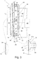
- the in Fig. 3 left detail can be seen that the wear-related removal over the longitudinal extent of the respective chopping blade 14 is uneven.
- the cutting-sharpness detection device 1 has at least one, here and preferably exactly one, magnet arrangement 17, which here and preferably has a magnetic excitation arrangement 18 and a flux-conducting device 19 which is magnetically coupled to the exciter arrangement 18.
- the basic structure of the magnet arrangement 17 results from the illustration according to FIG Fig. 3 , Here and preferably, it is provided that the magnet arrangement 17 provides a pole arrangement 20 which is fixed relative to the measuring drum 13 and which forms at least one magnetic pole 21-23 with a pole face for conducting out magnetic flux.
- a pole surface is in Fig. 3 for the pole 21 has been exemplified by the reference numeral 21a.
- the knife drum 13 of in Fig. 1 shown forage harvester 3 is axially divided into two and has seen in the direction of travel on a left drum half and a right drum half.
- Fig. 2 shows the right half of the drum.
- the left drum half is constructed analogously and also equipped with a proposed cutting edge detection device 1.
- Fig. 3 shows that at least one of the exciter assembly 18 excited magnetic circuit 38, 39 is closed by the respective chopping knife 14. Given the fact that the resulting magnetic flux in the respective magnetic circuit 38, 39 for a given magnetic excitation on the geometry and width B of the respective air gap 30-32 depends, is with a view of the illustration according to Fig. 2 Clear that based on the resulting magnetic flux, the cutting severity of the respective chopping blade 14 can be determined.
- the change in the magnetic flux represents the cutting severity compared to the situation with wear-free chopper blade 14.
- the value for this change thus represents the cutting severity.
- a value for the wear-related width of at least one air gap 30-32 of the air gap arrangement 29 or the wear-related geometry of the cutting edge 16 of the relevant chopper blade 14 is calculated from the at least one determined magnetic measured variable, which then also represents the cutting severity.
- the proposed cutting edge detection device 1 has a measuring arrangement 44 and an evaluation unit 45, wherein the measuring arrangement 44 generally detects at least one magnetic parameter relating to the magnetic flux in at least one magnetic circuit 38, 39 excited by the excitation system 18 and wherein the evaluation unit 45 also In general, the cutting severity of the respective chopper blade 14 is determined from the at least one detected measured variable. How this is done in detail will be explained below.
- the pole arrangement 20 has at least two magnetic poles 21-23 spaced apart from each other along the chopping blade 14 passing the pole arrangement 20, each forming an air gap 30-32 of the air gap arrangement 29 together with the chopper blade 14 and between those of the Magnetic exciter 18 generated magnetic flux in the chopper blade 14 is longitudinally guided.
- the cutting severity of the chopper blade 14 can also be determined in the longitudinal section L 1 , L 2 between the two poles 21-23. This is in Fig. 3 shown for a total of three poles 21-23.
- the separate determination of the cutting severity for different longitudinal sections L 1 , L 2 of the relevant chopper blade 14 is particularly useful when the wear of the chopper blades 14 changes over the longitudinal extent of the chopping blades 14. In fact, it is usually the case that the wear on the outer sides of the cutterhead 13 is greater than in the middle of the cutterhead 13, so that a spherical shaping results accordingly for the cutterhead 13.
- the pole arrangement 20 forms at least three magnetic poles 21-23 spaced from each other along the chopper blade 14 passing the pole arrangement 20, each of which together forms an air gap 30-32 of the air gap arrangement 29 with the pole arrangement Form 20 passing chopper 14.
- This is in Fig. 3 shown.
- at least one of the poles 21-23, here and preferably the pole 22, is part of two magnetic circuits 38, 39 excited by the magnetic exciter arrangement 18.
- a determination of the magnetic flux flowing through the two magnetic circuits 38, 39 thus provides, as mentioned above, information about the cutting severity of the respective chopper blade 14 in the longitudinal sections L 1 and L 2 .
- a particularly low-loss construction of the magnetic circuits 38, 39 results from the fact that at least a portion of the poles 21-23, here and preferably all poles 21-23, of the pole arrangement 20 are arranged along the cutting edge 16 of the chopper blade 14 passing the pole arrangement 20.
- a structurally easily implementable embodiment of the flux-conducting device 19 again shows Fig. 3 ,
- the flux guide device 19 has a central portion 47, from which the poles 21-23 of the pole arrangement 20 branch off.
- the central portion 27 of the flux guide 19 is designed here and preferably straight.
- the central portion 27 of the flux guide 19, as in Fig. 3 shown, along the cutting edge 16 of the pole assembly 20 passing chopping blade 14 extends. This results in an overall symmetrical structure of the flux guide device 19, which further simplifies the determination of the cutting severity of the respective chopper blade 14.
- the excitation arrangement 18 has at least one excitation magnet 48, 49, which is designed as a permanent magnet.
- the excitation magnet 48, 49 may also be an electromagnet.
- the exciter magnets 48, 49 in a portion of the flux guide 19, here in the central portion 47 of the flux guide 19, respectively.
- the measuring arrangement 44 has here and preferably at least one measuring unit 55-57 for detecting the at least one magnetic flux-based measured variable.
- the Fig. 3 shows a particularly simple embodiment of the measuring units 55-57.
- a measuring unit 55-57 each have a coil arrangement, which is traversed by the magnetic flux in the flux-conducting device 19.
- the above-mentioned air gap arrangement 29 is generated cyclically and canceled, so that a correspondingly cyclical change of the magnetic flux in the time domain results in at least one of the magnetic circuits 38, 39.
- the measuring unit 55-57 as the measured variable preferably detects the voltage induced in the coil arrangement.
- the measured quantity corresponds to the first derivative of the relevant magnetic flux in the time range, from which, possibly with reference to the wear-free state, a value for the cutting severity of the respective chopper blade 14 can be determined.
- the measured variable determined by the measuring arrangement 44 changes as a function of the cutting severity.
- the cutting severity can be derived from the measured value determined.
- a learning process is provided, in which the respective measured variable for different wear conditions is detected and stored. From these values, a characteristic field can be formed which forms the basis for the later determination of the cutting severity, that is to say a value which represents the cutting severity.
- the evaluation unit 45 determines the cutting severity of the respective chopper blade 14 from an amount, in particular a peak value, of the at least one measured variable and / or a profile of the at least one measured variable, respectively during a rotation of the cutterhead 13.
- the movement of the chopper blades 14 results in a continuous change in the magnetic fluxes in the respective magnetic circuits 38, 39, which depends on the cutting severity and which can easily be detected via the induced voltage mentioned above.
- the magnet assembly 17 described above is also according to another essential aspect of the proposed solution outside the Materialzuström Anlagens M positioned. This has the advantage that the components of the magnet arrangement 17 are not subject to any or at least no significant wear due to passing material of the crop stream S.
- Fig. 1 shows various alternative installation locations for the magnet assembly 17 in question.
- the alternatives shown have in common that the magnet assembly 17 is positioned at a point at which the crop stream S is passed after its comminution in the effective range of the chopper blade 14 and counter-blade 15.
- the magnet arrangement 17 is therefore not arranged in the region in front of the aforementioned effective region. In this way, the magnet arrangement 17 does not come into contact with the still comparatively coarse, unhardened material of the crop stream S, but at most with the comminuted material or with no material whatsoever.
- the magnet assembly 17, as Fig. 1 for all alternatives of the arrangement outside the range between the cutterhead 13 and the drum housing 2a through which the comminuted crop is led away positioned.
- the magnet arrangement 17 is positioned outside the drum housing 2a surrounding the cutterhead 13 or outside the drum base 58, drum back 59 and the drum rear wall 60.
- the magnet arrangement 17 is positioned in the direction of rotation of the cutterhead 13 behind the counter-blade 15, here and preferably vertically below the counter-blade 15.
- Installation locations shown by way of example ensure that the magnet arrangement 17 does not come into contact with the crop stream S either before its comminution in said active area or after its comminution in said active area.
- the magnet arrangement 17 is positioned within the area between the cutterhead 13 and drum housing 2 a, through which the comminuted crop stream S is led away. Although the magnet arrangement 17 comes into contact with the material of the crop stream S, it is not exposed to such a high level of wear as in the area of an arrangement before comminution by means of the chopper plant, in particular before the effective area or within the material inflow area M.
- the drum housing 2a here and preferably comprises a drum base 58, a drum back 59 and a drum rear wall 60, wherein the cutterhead 13 rotates with respect to the direction of gravity between the drum bottom 58 and the drum back 59.
- an opening is provided in the rear part of the chopper 2, through which the crop stream S is guided in an ejection channel 12.
- the crop stream S processing facilities may be provided as a grain cracker, in particular further unlock the crop, for example corn kernels.
- a particularly preferred installation location of the magnet arrangement 17, such as Fig. 1 shows, either on the drum bottom 58 or the back of the drum 59th
- a non-magnetic material such as stainless steel.
Landscapes
- Life Sciences & Earth Sciences (AREA)
- Environmental Sciences (AREA)
- Physics & Mathematics (AREA)
- General Physics & Mathematics (AREA)
- Crushing And Pulverization Processes (AREA)
- Threshing Machine Elements (AREA)
- Harvester Elements (AREA)
Applications Claiming Priority (1)
| Application Number | Priority Date | Filing Date | Title |
|---|---|---|---|
| DE102017129778.2A DE102017129778A1 (de) | 2017-12-13 | 2017-12-13 | Feldhäcksler |
Publications (2)
| Publication Number | Publication Date |
|---|---|
| EP3498080A1 true EP3498080A1 (fr) | 2019-06-19 |
| EP3498080B1 EP3498080B1 (fr) | 2022-08-17 |
Family
ID=63857775
Family Applications (1)
| Application Number | Title | Priority Date | Filing Date |
|---|---|---|---|
| EP18200321.0A Active EP3498080B1 (fr) | 2017-12-13 | 2018-10-15 | Ramasseuse-hacheuse |
Country Status (3)
| Country | Link |
|---|---|
| US (1) | US11109537B2 (fr) |
| EP (1) | EP3498080B1 (fr) |
| DE (1) | DE102017129778A1 (fr) |
Cited By (1)
| Publication number | Priority date | Publication date | Assignee | Title |
|---|---|---|---|---|
| EP4461120A1 (fr) | 2023-05-11 | 2024-11-13 | CLAAS Selbstfahrende Erntemaschinen GmbH | Ramasseuse-hacheuse et procédé de détection de corps étrangers métalliques |
Families Citing this family (5)
| Publication number | Priority date | Publication date | Assignee | Title |
|---|---|---|---|---|
| US10893645B2 (en) * | 2018-06-15 | 2021-01-19 | Bourgault Industries Ltd. | Mobile bale and feed processor and method |
| DE102020000725B4 (de) * | 2020-02-04 | 2021-10-28 | Maschinenfabrik Bernard Krone GmbH & Co. KG | Landwirtschaftliche Arbeitsmaschine mit einer Messanordnung, Messanordnung für die landwirtschaftliche Arbeitsmaschine und Verfahren zum Messen einer Kontur eines sich bewegenden Bauteils der landwirtschaftlichen Arbeitsmaschine |
| DE102020125434A1 (de) | 2020-09-29 | 2022-03-31 | Claas Selbstfahrende Erntemaschinen Gmbh | Landwirtschaftliche Maschine mit NIR-Sensor und Datenverarbeitungssystem |
| GB202020465D0 (en) * | 2020-12-23 | 2021-02-03 | Agco Int Gmbh | Forage harvester |
| US20240365718A1 (en) * | 2023-05-01 | 2024-11-07 | Deere & Company | Pre-cutter assembly for a baler implement |
Citations (5)
| Publication number | Priority date | Publication date | Assignee | Title |
|---|---|---|---|---|
| US4198006A (en) * | 1978-10-30 | 1980-04-15 | Sperry Corporation | Magnetic clearance sensor |
| EP0943888A2 (fr) * | 1998-03-20 | 1999-09-22 | Deere & Company | Dispositif pour surveiller la distance de deux pièces conductrices et magnétiques mobiles l'une par rapport à l'autre |
| DE102014218408A1 (de) | 2013-10-31 | 2015-04-30 | Deere & Company | Anordnung zur Erfassung der Schärfe von Häckselmessern |
| US20150323301A1 (en) * | 2014-05-12 | 2015-11-12 | The University Of Akron | High sensitivity inductive sensor for measuring blade tip clearance |
| EP3363281A1 (fr) * | 2017-02-21 | 2018-08-22 | CLAAS Selbstfahrende Erntemaschinen GmbH | Dispositif de détection permettant de détecter un état d'usure d'un mécanisme hacheur |
Family Cites Families (5)
| Publication number | Priority date | Publication date | Assignee | Title |
|---|---|---|---|---|
| US3757501A (en) * | 1971-10-29 | 1973-09-11 | Sperry Rand Corp | Static magnetic field metal detector |
| US4412212A (en) * | 1981-08-10 | 1983-10-25 | Deere & Company | Shearbar clearance detector |
| DE10235919B4 (de) * | 2002-07-30 | 2006-02-09 | Deere & Company, Moline | Verfahren und Anordnung zur Bestimmung der Schärfe von Häckselmessern |
| US7430845B2 (en) * | 2005-12-14 | 2008-10-07 | Deere & Company | Harvesting machine with a measuring device for capturing the throughput of collected crop material |
| DE102009049265A1 (de) * | 2009-07-03 | 2012-07-05 | Claas Saulgau Gmbh | Verfahren und Vorrichtung zur Erkennung der Schneidschärfe von Häckselmessern eines Feldhäckslers |
-
2017
- 2017-12-13 DE DE102017129778.2A patent/DE102017129778A1/de not_active Withdrawn
-
2018
- 2018-10-15 EP EP18200321.0A patent/EP3498080B1/fr active Active
- 2018-12-12 US US16/217,537 patent/US11109537B2/en active Active
Patent Citations (5)
| Publication number | Priority date | Publication date | Assignee | Title |
|---|---|---|---|---|
| US4198006A (en) * | 1978-10-30 | 1980-04-15 | Sperry Corporation | Magnetic clearance sensor |
| EP0943888A2 (fr) * | 1998-03-20 | 1999-09-22 | Deere & Company | Dispositif pour surveiller la distance de deux pièces conductrices et magnétiques mobiles l'une par rapport à l'autre |
| DE102014218408A1 (de) | 2013-10-31 | 2015-04-30 | Deere & Company | Anordnung zur Erfassung der Schärfe von Häckselmessern |
| US20150323301A1 (en) * | 2014-05-12 | 2015-11-12 | The University Of Akron | High sensitivity inductive sensor for measuring blade tip clearance |
| EP3363281A1 (fr) * | 2017-02-21 | 2018-08-22 | CLAAS Selbstfahrende Erntemaschinen GmbH | Dispositif de détection permettant de détecter un état d'usure d'un mécanisme hacheur |
Cited By (2)
| Publication number | Priority date | Publication date | Assignee | Title |
|---|---|---|---|---|
| EP4461120A1 (fr) | 2023-05-11 | 2024-11-13 | CLAAS Selbstfahrende Erntemaschinen GmbH | Ramasseuse-hacheuse et procédé de détection de corps étrangers métalliques |
| DE102023112484A1 (de) | 2023-05-11 | 2024-11-14 | Claas Selbstfahrende Erntemaschinen Gmbh | Feldhäcksler sowie Verfahren zur Detektion von metallischen Fremdkörpern |
Also Published As
| Publication number | Publication date |
|---|---|
| EP3498080B1 (fr) | 2022-08-17 |
| DE102017129778A1 (de) | 2019-06-13 |
| US11109537B2 (en) | 2021-09-07 |
| US20190174680A1 (en) | 2019-06-13 |
Similar Documents
| Publication | Publication Date | Title |
|---|---|---|
| EP3363281B1 (fr) | Dispositif de détection permettant de détecter un état d'usure d'un mécanisme hacheur | |
| EP3498080B1 (fr) | Ramasseuse-hacheuse | |
| EP1522214B1 (fr) | Machine de récolte avec un dispositif de contrôle de l'affutage de couteaux de coupe et/ou leur distance au contre-couteau | |
| EP1442652B1 (fr) | Dispositif pour mesurer ou contrôler la distance entre un contre couteau et un couteau hacheur | |
| DE102011005317B4 (de) | Messsystem zur Ermittlung des Verschleißzustandes von Häckselmessern | |
| EP2764767B1 (fr) | Moissonneuse, notamment ramasseuse-hâcheuse | |
| BE1022370B1 (de) | Anordnung zur erfassung der scharfe von hackselmessern | |
| EP3738427B1 (fr) | Dispositif de détection de tranchant | |
| DE102010037915A1 (de) | Vorrichtung zur Ermittlung der Schärfe von Schmeidmessern | |
| DE102004016089B4 (de) | Einrichtung zur Verstellung der Position einer Gegenschneide gegenüber einer Häckseleinrichtung | |
| DE2943828A1 (de) | Abstandsmesschaltung | |
| DE102019112968A1 (de) | Schneidschärfendetektionseinrichtung | |
| DE102017201423A1 (de) | Anordnung zur Erkennung des Verschleißgrades von Häckselmessern einer Häckseltrommel eines Feldhäckslers | |
| DE102019112965A1 (de) | Fahrerassistenzsystem eines Feldhäckslers | |
| DE102017117966A1 (de) | Stellvorrichtung eines Häckselwerks eines Feldhäckslers | |
| EP1905292A2 (fr) | Dispositif de mesure destiné à la mesure de paramètres | |
| DE102019112973A1 (de) | Fahrerassistenzsystem eines Feldhäckslers | |
| EP1614342B1 (fr) | Dispositif avec capteur de cliquetis | |
| DE102010021746A1 (de) | Vorrichtung und Verfahren zur Bestimmung des Verschleißes an Schneidmessern von Häckslern | |
| EP4122313B1 (fr) | Procédé de détermination de l'état d'usure d'une contre-lame agencée sur un porte-contre-lame, ainsi que ramasseuse-hacheuse autonome | |
| DE19942399C1 (de) | Verfahren und Vorrichtung zum Einstellen des Schneidspaltes an Häckslern | |
| EP4483702B1 (fr) | Récolteuse-hacheuse | |
| DE10051553C2 (de) | Einstellvorrichtung für den Schneidspalt an Häckslern | |
| DE19934982C2 (de) | Einstellvorrichtung für den Schneidspalt an Häckslern | |
| EP4477048A1 (fr) | Récolteuse-hacheuse |
Legal Events
| Date | Code | Title | Description |
|---|---|---|---|
| PUAI | Public reference made under article 153(3) epc to a published international application that has entered the european phase |
Free format text: ORIGINAL CODE: 0009012 |
|
| STAA | Information on the status of an ep patent application or granted ep patent |
Free format text: STATUS: THE APPLICATION HAS BEEN PUBLISHED |
|
| AK | Designated contracting states |
Kind code of ref document: A1 Designated state(s): AL AT BE BG CH CY CZ DE DK EE ES FI FR GB GR HR HU IE IS IT LI LT LU LV MC MK MT NL NO PL PT RO RS SE SI SK SM TR |
|
| AX | Request for extension of the european patent |
Extension state: BA ME |
|
| STAA | Information on the status of an ep patent application or granted ep patent |
Free format text: STATUS: REQUEST FOR EXAMINATION WAS MADE |
|
| 17P | Request for examination filed |
Effective date: 20191219 |
|
| RBV | Designated contracting states (corrected) |
Designated state(s): AL AT BE BG CH CY CZ DE DK EE ES FI FR GB GR HR HU IE IS IT LI LT LU LV MC MK MT NL NO PL PT RO RS SE SI SK SM TR |
|
| STAA | Information on the status of an ep patent application or granted ep patent |
Free format text: STATUS: EXAMINATION IS IN PROGRESS |
|
| 17Q | First examination report despatched |
Effective date: 20210927 |
|
| GRAP | Despatch of communication of intention to grant a patent |
Free format text: ORIGINAL CODE: EPIDOSNIGR1 |
|
| STAA | Information on the status of an ep patent application or granted ep patent |
Free format text: STATUS: GRANT OF PATENT IS INTENDED |
|
| INTG | Intention to grant announced |
Effective date: 20220331 |
|
| GRAS | Grant fee paid |
Free format text: ORIGINAL CODE: EPIDOSNIGR3 |
|
| GRAA | (expected) grant |
Free format text: ORIGINAL CODE: 0009210 |
|
| STAA | Information on the status of an ep patent application or granted ep patent |
Free format text: STATUS: THE PATENT HAS BEEN GRANTED |
|
| AK | Designated contracting states |
Kind code of ref document: B1 Designated state(s): AL AT BE BG CH CY CZ DE DK EE ES FI FR GB GR HR HU IE IS IT LI LT LU LV MC MK MT NL NO PL PT RO RS SE SI SK SM TR |
|
| REG | Reference to a national code |
Ref country code: CH Ref legal event code: EP |
|
| REG | Reference to a national code |
Ref country code: DE Ref legal event code: R096 Ref document number: 502018010406 Country of ref document: DE |
|
| REG | Reference to a national code |
Ref country code: IE Ref legal event code: FG4D Free format text: LANGUAGE OF EP DOCUMENT: GERMAN |
|
| REG | Reference to a national code |
Ref country code: AT Ref legal event code: REF Ref document number: 1511541 Country of ref document: AT Kind code of ref document: T Effective date: 20220915 |
|
| REG | Reference to a national code |
Ref country code: NL Ref legal event code: MP Effective date: 20220817 |
|
| REG | Reference to a national code |
Ref country code: LT Ref legal event code: MG9D |
|
| PG25 | Lapsed in a contracting state [announced via postgrant information from national office to epo] |
Ref country code: SE Free format text: LAPSE BECAUSE OF FAILURE TO SUBMIT A TRANSLATION OF THE DESCRIPTION OR TO PAY THE FEE WITHIN THE PRESCRIBED TIME-LIMIT Effective date: 20220817 Ref country code: RS Free format text: LAPSE BECAUSE OF FAILURE TO SUBMIT A TRANSLATION OF THE DESCRIPTION OR TO PAY THE FEE WITHIN THE PRESCRIBED TIME-LIMIT Effective date: 20220817 Ref country code: PT Free format text: LAPSE BECAUSE OF FAILURE TO SUBMIT A TRANSLATION OF THE DESCRIPTION OR TO PAY THE FEE WITHIN THE PRESCRIBED TIME-LIMIT Effective date: 20221219 Ref country code: NO Free format text: LAPSE BECAUSE OF FAILURE TO SUBMIT A TRANSLATION OF THE DESCRIPTION OR TO PAY THE FEE WITHIN THE PRESCRIBED TIME-LIMIT Effective date: 20221117 Ref country code: NL Free format text: LAPSE BECAUSE OF FAILURE TO SUBMIT A TRANSLATION OF THE DESCRIPTION OR TO PAY THE FEE WITHIN THE PRESCRIBED TIME-LIMIT Effective date: 20220817 Ref country code: LV Free format text: LAPSE BECAUSE OF FAILURE TO SUBMIT A TRANSLATION OF THE DESCRIPTION OR TO PAY THE FEE WITHIN THE PRESCRIBED TIME-LIMIT Effective date: 20220817 Ref country code: LT Free format text: LAPSE BECAUSE OF FAILURE TO SUBMIT A TRANSLATION OF THE DESCRIPTION OR TO PAY THE FEE WITHIN THE PRESCRIBED TIME-LIMIT Effective date: 20220817 Ref country code: FI Free format text: LAPSE BECAUSE OF FAILURE TO SUBMIT A TRANSLATION OF THE DESCRIPTION OR TO PAY THE FEE WITHIN THE PRESCRIBED TIME-LIMIT Effective date: 20220817 |
|
| PG25 | Lapsed in a contracting state [announced via postgrant information from national office to epo] |
Ref country code: PL Free format text: LAPSE BECAUSE OF FAILURE TO SUBMIT A TRANSLATION OF THE DESCRIPTION OR TO PAY THE FEE WITHIN THE PRESCRIBED TIME-LIMIT Effective date: 20220817 Ref country code: IS Free format text: LAPSE BECAUSE OF FAILURE TO SUBMIT A TRANSLATION OF THE DESCRIPTION OR TO PAY THE FEE WITHIN THE PRESCRIBED TIME-LIMIT Effective date: 20221217 Ref country code: HR Free format text: LAPSE BECAUSE OF FAILURE TO SUBMIT A TRANSLATION OF THE DESCRIPTION OR TO PAY THE FEE WITHIN THE PRESCRIBED TIME-LIMIT Effective date: 20220817 Ref country code: GR Free format text: LAPSE BECAUSE OF FAILURE TO SUBMIT A TRANSLATION OF THE DESCRIPTION OR TO PAY THE FEE WITHIN THE PRESCRIBED TIME-LIMIT Effective date: 20221118 |
|
| PG25 | Lapsed in a contracting state [announced via postgrant information from national office to epo] |
Ref country code: SM Free format text: LAPSE BECAUSE OF FAILURE TO SUBMIT A TRANSLATION OF THE DESCRIPTION OR TO PAY THE FEE WITHIN THE PRESCRIBED TIME-LIMIT Effective date: 20220817 Ref country code: RO Free format text: LAPSE BECAUSE OF FAILURE TO SUBMIT A TRANSLATION OF THE DESCRIPTION OR TO PAY THE FEE WITHIN THE PRESCRIBED TIME-LIMIT Effective date: 20220817 Ref country code: ES Free format text: LAPSE BECAUSE OF FAILURE TO SUBMIT A TRANSLATION OF THE DESCRIPTION OR TO PAY THE FEE WITHIN THE PRESCRIBED TIME-LIMIT Effective date: 20220817 Ref country code: DK Free format text: LAPSE BECAUSE OF FAILURE TO SUBMIT A TRANSLATION OF THE DESCRIPTION OR TO PAY THE FEE WITHIN THE PRESCRIBED TIME-LIMIT Effective date: 20220817 Ref country code: CZ Free format text: LAPSE BECAUSE OF FAILURE TO SUBMIT A TRANSLATION OF THE DESCRIPTION OR TO PAY THE FEE WITHIN THE PRESCRIBED TIME-LIMIT Effective date: 20220817 |
|
| REG | Reference to a national code |
Ref country code: DE Ref legal event code: R097 Ref document number: 502018010406 Country of ref document: DE |
|
| PG25 | Lapsed in a contracting state [announced via postgrant information from national office to epo] |
Ref country code: SK Free format text: LAPSE BECAUSE OF FAILURE TO SUBMIT A TRANSLATION OF THE DESCRIPTION OR TO PAY THE FEE WITHIN THE PRESCRIBED TIME-LIMIT Effective date: 20220817 Ref country code: MC Free format text: LAPSE BECAUSE OF FAILURE TO SUBMIT A TRANSLATION OF THE DESCRIPTION OR TO PAY THE FEE WITHIN THE PRESCRIBED TIME-LIMIT Effective date: 20220817 Ref country code: EE Free format text: LAPSE BECAUSE OF FAILURE TO SUBMIT A TRANSLATION OF THE DESCRIPTION OR TO PAY THE FEE WITHIN THE PRESCRIBED TIME-LIMIT Effective date: 20220817 |
|
| REG | Reference to a national code |
Ref country code: CH Ref legal event code: PL |
|
| P01 | Opt-out of the competence of the unified patent court (upc) registered |
Effective date: 20230516 |
|
| PLBE | No opposition filed within time limit |
Free format text: ORIGINAL CODE: 0009261 |
|
| STAA | Information on the status of an ep patent application or granted ep patent |
Free format text: STATUS: NO OPPOSITION FILED WITHIN TIME LIMIT |
|
| PG25 | Lapsed in a contracting state [announced via postgrant information from national office to epo] |
Ref country code: LU Free format text: LAPSE BECAUSE OF NON-PAYMENT OF DUE FEES Effective date: 20221015 Ref country code: AL Free format text: LAPSE BECAUSE OF FAILURE TO SUBMIT A TRANSLATION OF THE DESCRIPTION OR TO PAY THE FEE WITHIN THE PRESCRIBED TIME-LIMIT Effective date: 20220817 |
|
| 26N | No opposition filed |
Effective date: 20230519 |
|
| GBPC | Gb: european patent ceased through non-payment of renewal fee |
Effective date: 20221117 |
|
| PG25 | Lapsed in a contracting state [announced via postgrant information from national office to epo] |
Ref country code: LI Free format text: LAPSE BECAUSE OF NON-PAYMENT OF DUE FEES Effective date: 20221031 Ref country code: FR Free format text: LAPSE BECAUSE OF NON-PAYMENT OF DUE FEES Effective date: 20221017 Ref country code: CH Free format text: LAPSE BECAUSE OF NON-PAYMENT OF DUE FEES Effective date: 20221031 |
|
| PG25 | Lapsed in a contracting state [announced via postgrant information from national office to epo] |
Ref country code: SI Free format text: LAPSE BECAUSE OF FAILURE TO SUBMIT A TRANSLATION OF THE DESCRIPTION OR TO PAY THE FEE WITHIN THE PRESCRIBED TIME-LIMIT Effective date: 20220817 |
|
| PG25 | Lapsed in a contracting state [announced via postgrant information from national office to epo] |
Ref country code: IE Free format text: LAPSE BECAUSE OF NON-PAYMENT OF DUE FEES Effective date: 20221015 Ref country code: GB Free format text: LAPSE BECAUSE OF NON-PAYMENT OF DUE FEES Effective date: 20221117 |
|
| PG25 | Lapsed in a contracting state [announced via postgrant information from national office to epo] |
Ref country code: HU Free format text: LAPSE BECAUSE OF FAILURE TO SUBMIT A TRANSLATION OF THE DESCRIPTION OR TO PAY THE FEE WITHIN THE PRESCRIBED TIME-LIMIT; INVALID AB INITIO Effective date: 20181015 |
|
| PG25 | Lapsed in a contracting state [announced via postgrant information from national office to epo] |
Ref country code: CY Free format text: LAPSE BECAUSE OF FAILURE TO SUBMIT A TRANSLATION OF THE DESCRIPTION OR TO PAY THE FEE WITHIN THE PRESCRIBED TIME-LIMIT Effective date: 20220817 |
|
| PG25 | Lapsed in a contracting state [announced via postgrant information from national office to epo] |
Ref country code: MK Free format text: LAPSE BECAUSE OF FAILURE TO SUBMIT A TRANSLATION OF THE DESCRIPTION OR TO PAY THE FEE WITHIN THE PRESCRIBED TIME-LIMIT Effective date: 20220817 Ref country code: IT Free format text: LAPSE BECAUSE OF FAILURE TO SUBMIT A TRANSLATION OF THE DESCRIPTION OR TO PAY THE FEE WITHIN THE PRESCRIBED TIME-LIMIT Effective date: 20220817 |
|
| PG25 | Lapsed in a contracting state [announced via postgrant information from national office to epo] |
Ref country code: TR Free format text: LAPSE BECAUSE OF FAILURE TO SUBMIT A TRANSLATION OF THE DESCRIPTION OR TO PAY THE FEE WITHIN THE PRESCRIBED TIME-LIMIT Effective date: 20220817 |
|
| PG25 | Lapsed in a contracting state [announced via postgrant information from national office to epo] |
Ref country code: BG Free format text: LAPSE BECAUSE OF FAILURE TO SUBMIT A TRANSLATION OF THE DESCRIPTION OR TO PAY THE FEE WITHIN THE PRESCRIBED TIME-LIMIT Effective date: 20220817 |
|
| PG25 | Lapsed in a contracting state [announced via postgrant information from national office to epo] |
Ref country code: MT Free format text: LAPSE BECAUSE OF FAILURE TO SUBMIT A TRANSLATION OF THE DESCRIPTION OR TO PAY THE FEE WITHIN THE PRESCRIBED TIME-LIMIT Effective date: 20220817 |
|
| REG | Reference to a national code |
Ref country code: AT Ref legal event code: MM01 Ref document number: 1511541 Country of ref document: AT Kind code of ref document: T Effective date: 20231015 |
|
| PG25 | Lapsed in a contracting state [announced via postgrant information from national office to epo] |
Ref country code: AT Free format text: LAPSE BECAUSE OF NON-PAYMENT OF DUE FEES Effective date: 20231015 |
|
| PG25 | Lapsed in a contracting state [announced via postgrant information from national office to epo] |
Ref country code: AT Free format text: LAPSE BECAUSE OF NON-PAYMENT OF DUE FEES Effective date: 20231015 |
|
| PGFP | Annual fee paid to national office [announced via postgrant information from national office to epo] |
Ref country code: DE Payment date: 20251021 Year of fee payment: 8 |
|
| PGFP | Annual fee paid to national office [announced via postgrant information from national office to epo] |
Ref country code: BE Payment date: 20251021 Year of fee payment: 8 |
|
| PGFP | Annual fee paid to national office [announced via postgrant information from national office to epo] |
Ref country code: AT Payment date: 20260410 Year of fee payment: 5 |