EP3498420A1 - Système de positionnement et machine de traitement du matériau - Google Patents
Système de positionnement et machine de traitement du matériau Download PDFInfo
- Publication number
- EP3498420A1 EP3498420A1 EP18211332.4A EP18211332A EP3498420A1 EP 3498420 A1 EP3498420 A1 EP 3498420A1 EP 18211332 A EP18211332 A EP 18211332A EP 3498420 A1 EP3498420 A1 EP 3498420A1
- Authority
- EP
- European Patent Office
- Prior art keywords
- carriage
- guide rail
- positioning system
- active rotor
- active
- Prior art date
- Legal status (The legal status is an assumption and is not a legal conclusion. Google has not performed a legal analysis and makes no representation as to the accuracy of the status listed.)
- Withdrawn
Links
- 239000000463 material Substances 0.000 title claims abstract description 25
- 238000005520 cutting process Methods 0.000 claims description 9
- 238000003801 milling Methods 0.000 claims description 5
- 238000002372 labelling Methods 0.000 claims description 4
- 238000003466 welding Methods 0.000 claims description 3
- 238000004804 winding Methods 0.000 claims description 3
- 238000007639 printing Methods 0.000 claims description 2
- 238000003860 storage Methods 0.000 description 3
- 238000010276 construction Methods 0.000 description 2
- 230000003287 optical effect Effects 0.000 description 2
- QJVKUMXDEUEQLH-UHFFFAOYSA-N [B].[Fe].[Nd] Chemical compound [B].[Fe].[Nd] QJVKUMXDEUEQLH-UHFFFAOYSA-N 0.000 description 1
- 239000003795 chemical substances by application Substances 0.000 description 1
- KPLQYGBQNPPQGA-UHFFFAOYSA-N cobalt samarium Chemical compound [Co].[Sm] KPLQYGBQNPPQGA-UHFFFAOYSA-N 0.000 description 1
- 238000005553 drilling Methods 0.000 description 1
- 230000000694 effects Effects 0.000 description 1
- 238000005516 engineering process Methods 0.000 description 1
- 238000007689 inspection Methods 0.000 description 1
- 238000009434 installation Methods 0.000 description 1
- 238000004519 manufacturing process Methods 0.000 description 1
- 229910001172 neodymium magnet Inorganic materials 0.000 description 1
- 229910000938 samarium–cobalt magnet Inorganic materials 0.000 description 1
Images


Classifications
-
- H—ELECTRICITY
- H02—GENERATION; CONVERSION OR DISTRIBUTION OF ELECTRIC POWER
- H02K—DYNAMO-ELECTRIC MACHINES
- H02K41/00—Propulsion systems in which a rigid body is moved along a path due to dynamo-electric interaction between the body and a magnetic field travelling along the path
- H02K41/02—Linear motors; Sectional motors
- H02K41/03—Synchronous motors; Motors moving step by step; Reluctance motors
- H02K41/031—Synchronous motors; Motors moving step by step; Reluctance motors of the permanent magnet type
-
- B—PERFORMING OPERATIONS; TRANSPORTING
- B23—MACHINE TOOLS; METAL-WORKING NOT OTHERWISE PROVIDED FOR
- B23Q—DETAILS, COMPONENTS, OR ACCESSORIES FOR MACHINE TOOLS, e.g. ARRANGEMENTS FOR COPYING OR CONTROLLING; MACHINE TOOLS IN GENERAL CHARACTERISED BY THE CONSTRUCTION OF PARTICULAR DETAILS OR COMPONENTS; COMBINATIONS OR ASSOCIATIONS OF METAL-WORKING MACHINES, NOT DIRECTED TO A PARTICULAR RESULT
- B23Q1/00—Members which are comprised in the general build-up of a form of machine, particularly relatively large fixed members
- B23Q1/01—Frames, beds, pillars or like members; Arrangement of ways
- B23Q1/012—Portals
-
- B—PERFORMING OPERATIONS; TRANSPORTING
- B23—MACHINE TOOLS; METAL-WORKING NOT OTHERWISE PROVIDED FOR
- B23Q—DETAILS, COMPONENTS, OR ACCESSORIES FOR MACHINE TOOLS, e.g. ARRANGEMENTS FOR COPYING OR CONTROLLING; MACHINE TOOLS IN GENERAL CHARACTERISED BY THE CONSTRUCTION OF PARTICULAR DETAILS OR COMPONENTS; COMBINATIONS OR ASSOCIATIONS OF METAL-WORKING MACHINES, NOT DIRECTED TO A PARTICULAR RESULT
- B23Q1/00—Members which are comprised in the general build-up of a form of machine, particularly relatively large fixed members
- B23Q1/25—Movable or adjustable work or tool supports
- B23Q1/44—Movable or adjustable work or tool supports using particular mechanisms
- B23Q1/56—Movable or adjustable work or tool supports using particular mechanisms with sliding pairs only, the sliding pairs being the first two elements of the mechanism
- B23Q1/60—Movable or adjustable work or tool supports using particular mechanisms with sliding pairs only, the sliding pairs being the first two elements of the mechanism two sliding pairs only, the sliding pairs being the first two elements of the mechanism
- B23Q1/62—Movable or adjustable work or tool supports using particular mechanisms with sliding pairs only, the sliding pairs being the first two elements of the mechanism two sliding pairs only, the sliding pairs being the first two elements of the mechanism with perpendicular axes, e.g. cross-slides
- B23Q1/621—Movable or adjustable work or tool supports using particular mechanisms with sliding pairs only, the sliding pairs being the first two elements of the mechanism two sliding pairs only, the sliding pairs being the first two elements of the mechanism with perpendicular axes, e.g. cross-slides a single sliding pair followed perpendicularly by a single sliding pair
-
- B—PERFORMING OPERATIONS; TRANSPORTING
- B23—MACHINE TOOLS; METAL-WORKING NOT OTHERWISE PROVIDED FOR
- B23Q—DETAILS, COMPONENTS, OR ACCESSORIES FOR MACHINE TOOLS, e.g. ARRANGEMENTS FOR COPYING OR CONTROLLING; MACHINE TOOLS IN GENERAL CHARACTERISED BY THE CONSTRUCTION OF PARTICULAR DETAILS OR COMPONENTS; COMBINATIONS OR ASSOCIATIONS OF METAL-WORKING MACHINES, NOT DIRECTED TO A PARTICULAR RESULT
- B23Q3/00—Devices holding, supporting, or positioning work or tools, of a kind normally removable from the machine
- B23Q3/155—Arrangements for automatic insertion or removal of tools, e.g. combined with manual handling
-
- B—PERFORMING OPERATIONS; TRANSPORTING
- B23—MACHINE TOOLS; METAL-WORKING NOT OTHERWISE PROVIDED FOR
- B23Q—DETAILS, COMPONENTS, OR ACCESSORIES FOR MACHINE TOOLS, e.g. ARRANGEMENTS FOR COPYING OR CONTROLLING; MACHINE TOOLS IN GENERAL CHARACTERISED BY THE CONSTRUCTION OF PARTICULAR DETAILS OR COMPONENTS; COMBINATIONS OR ASSOCIATIONS OF METAL-WORKING MACHINES, NOT DIRECTED TO A PARTICULAR RESULT
- B23Q39/00—Metal-working machines incorporating a plurality of sub-assemblies, each capable of performing a metal-working operation
- B23Q39/02—Metal-working machines incorporating a plurality of sub-assemblies, each capable of performing a metal-working operation the sub-assemblies being capable of being brought to act at a single operating station
- B23Q39/021—Metal-working machines incorporating a plurality of sub-assemblies, each capable of performing a metal-working operation the sub-assemblies being capable of being brought to act at a single operating station with a plurality of toolheads per workholder, whereby the toolhead is a main spindle, a multispindle, a revolver or the like
- B23Q39/022—Metal-working machines incorporating a plurality of sub-assemblies, each capable of performing a metal-working operation the sub-assemblies being capable of being brought to act at a single operating station with a plurality of toolheads per workholder, whereby the toolhead is a main spindle, a multispindle, a revolver or the like with same working direction of toolheads on same workholder
- B23Q39/023—Metal-working machines incorporating a plurality of sub-assemblies, each capable of performing a metal-working operation the sub-assemblies being capable of being brought to act at a single operating station with a plurality of toolheads per workholder, whereby the toolhead is a main spindle, a multispindle, a revolver or the like with same working direction of toolheads on same workholder simultaneous working of toolheads
-
- H—ELECTRICITY
- H02—GENERATION; CONVERSION OR DISTRIBUTION OF ELECTRIC POWER
- H02K—DYNAMO-ELECTRIC MACHINES
- H02K16/00—Machines with more than one rotor or stator
-
- H—ELECTRICITY
- H02—GENERATION; CONVERSION OR DISTRIBUTION OF ELECTRIC POWER
- H02K—DYNAMO-ELECTRIC MACHINES
- H02K2201/00—Specific aspects not provided for in the other groups of this subclass relating to the magnetic circuits
- H02K2201/18—Machines moving with multiple degrees of freedom
-
- H—ELECTRICITY
- H02—GENERATION; CONVERSION OR DISTRIBUTION OF ELECTRIC POWER
- H02K—DYNAMO-ELECTRIC MACHINES
- H02K2213/00—Specific aspects, not otherwise provided for and not covered by codes H02K2201/00 - H02K2211/00
- H02K2213/03—Machines characterised by numerical values, ranges, mathematical expressions or similar information
Definitions
- the invention relates to a positioning system for positioning at least two functional units along two axes, comprising a guide rail system with a first guide rail and with a parallel to the first guide rail and at a distance therefrom arranged second guide rail, a first carriage, which in the longitudinal direction of the guide rails movable the first guide rail and is mounted on the second guide rail, and a second carriage, which is mounted in the longitudinal direction of the guide rails movable on the first guide rail and on the second guide rail, wherein a first functional unit on the first carriage is arranged transversely to the longitudinal direction of the guide rails , and wherein a second functional unit is arranged to be movable on the second carriage transversely to the longitudinal direction of the guide rails.
- Positioning systems with a carriage which can be moved on two guide rails and a functional unit which can be moved along the carriage have been known for a long time and are used in many fields of technology.
- Cartesian position data can be transferred directly to a controller of the positioning system and converted into movement data for the carriage and for the functional unit.
- a second functional unit may be provided which, for example, comprises a second tool.
- it can be arranged on a second slide.
- a processing machine with a corresponding positioning system is offered, for example, under the type designation "D3" by Zünd Systemtechnik AG.
- a disadvantage of corresponding positioning systems is the high cost of driving the carriage. While both carriages can be easily stored on common guide rails, the drive of the carriage is usually via completely independent drive systems, which have for each carriage its own drive motor and guided over the entire length of the travel drive belt.
- a positioning system for positioning at least two functional units along two axes, comprising: a guide rail system having a first guide rail and having a first carriage parallel to the first guide rail and spaced therefrom; which is movably mounted in the longitudinal direction of the guide rails on the first guide rail and on the second guide rail, and a second carriage which is mounted in the longitudinal direction of the guide rails movable on the first guide rail and on the second guide rail, wherein a first functional unit on the first carriage is arranged transversely to the longitudinal direction of the guide rails, and wherein a second functional unit is arranged on the second carriage transversely to the longitudinal direction of the guide rails movable, which consgebi thereby
- the first guide rail is assigned a first passive stator
- the second guide rail is assigned a second passive stator (131)
- the first carriage has a first active rotor which interacts with the first passive stator as a linear motor, and a second active rotor , which cooperates with the second passive stator
- Each of the slides is driven according to the invention by two linear motors, wherein the active rotor of the linear motors are respectively associated with the carriage, and wherein the passive stators of the linear motors are respectively associated with the guide rails.
- two linear motors use the same passive stator, so that overall the effort for the construction of the positioning system is reduced.
- the active rotor of the first carriage and the active rotor of the second carriage may differ in their electrical and / or mechanical dimensioning from each other.
- the functional units may differ in particular in their weight and / or in their movement pattern.
- a different mechanical and / or electrical dimensioning of the active rotor makes it possible to provide linear motors for each of the two carriages, which are optimized for the functional unit arranged on the respective carriage.
- the common use of the passive stators can be maintained in two different sized linear motors.
- the active sliders of the first sled and the active sliders of the second sled may differ in number and / or spacing of magnetic poles. For example, varying the number and / or spacing of the magnetic poles of the active rotors allows for different step sizes when the corresponding linear motors are operated as stepper motors.
- the active rotor of the first carriage and the active rotor of the second carriage may differ in a winding number and / or a line cross-section of magnetic coils.
- the magnetic field strengths generated by the magnetic coils can be changed.
- the active runners of the first carriage and the active runners of the second carriage may be designed for different conveying forces.
- the corresponding linear motors can be optimized for differently sized functional units and / or for different dynamic movement patterns.
- the active rotor of the first carriage and the active rotor of the second carriage may be designed for different positioning accuracies. For example, different accuracy requirements for the positioning accuracy of the respective functional units can be taken into account.
- the drives provided for moving the functional units along the carriages can likewise be dimensioned differently in order to take account of different weights, movement patterns and / or positioning accuracies.
- this may comprise one or more further carriages in addition to the first carriage and the second carriage.
- These further carriages may be preferably similar to the first and second carriages.
- the object is achieved by a material processing machine which is equipped with a positioning system according to the above statements.
- one of the functional units may be a unit for mechanical cutting, milling and / or engraving.
- one of the functional units may comprise a focusing unit for a laser beam, preferably for welding, cutting and / or engraving.
- one of the functional units may comprise a receptacle in which either a mechanical cutting, milling and / or engraving unit or a focusing unit for a laser beam is used, preferably for welding, cutting and / or engraving can be. It is thereby possible to equip the processing machine as required with different processing tools.
- one of the functional units may comprise a unit for marking, labeling, printing and / or labeling.
- Further possible functional units are, for example, a single or multi-axis articulated-arm robot, an optical or non-optical inspection head, or a suction gripper.
- FIG. 1 a positioning system 100 is shown in a plan view.
- the positioning system 100 comprises parallel guide rails 101,102, which are arranged at a distance from each other.
- a first carriage 110 is mounted so that it is movable in the longitudinal direction of the guide rails 101,102.
- the mounting of the carriage 110 on the guide rails 101,102 for example via slide bearings, roller bearings, and / or non-contact air or magnetic bearings can be performed.
- a first functional unit 111 is mounted so that the functional unit 111 can be moved transversely to the longitudinal direction of the guide rails 101, 102 along the carriage 110.
- two parallel guide rods 112,113 are arranged on the carriage 110, on which the functional unit 111 is movably mounted.
- one or both of the guide rods 112, 113 is designed as a spindle rod and cooperates with spindle nuts, not shown, in the functional unit 111 as a spindle drive.
- a drive and control unit 115 for the movement of the functional unit 111 along the carriage 110 is arranged.
- drives of the functional unit 111 are also conceivable, such as belt drives or electromagnetic linear drives.
- a second carriage 120 is also mounted on the guide rails 101,102, wherein details of the storage of the storage of the carriage 110 correspond.
- a functional unit 121 is also arranged movable.
- guide rods 122, 123 and a drive and control unit 125 are provided.
- the drive of the carriages 110, 120 along the guide rails 101, 102 takes place via an electromagnetic linear drive.
- passive stators 130,131 are arranged.
- the passive stators 130,131 each include a linear array of magnets 135 with alternating poles orientation, of which only a few are shown for clarity.
- the magnets 135 are permanent magnets, here, for example, samarium cobalt or neodymium-iron-boron magnets can be used.
- the magnets 135 of the passive stators 130, 131 may be DC energized electromagnets.
- the carriage 110 is equipped in the region of the passive stators 130,131 with two active rotors 140,141.
- the active rotors 140, 141 each include an array of electromagnets 145, only a few of which are shown.
- the carriage 120 is also equipped with two active rotors 146,147 in the region of the passive stators 130,131.
- the active rotors 146, 114 each include an array of electromagnets 148.
- the electromagnets 145, 148 are controlled by a controller 150 via flexible lines 151, 152, 153, 154 so that the active rotors 140, 141, 146, 477 interact with the passive stators 130, 131 as linear motors and the carriages 110, 120 move independently of one another along the guide rails 101, 102 to desired positions.
- the drive and control units 115, 125 of the carriages 110, 120 are controlled via flexible lines 155, 156 in such a way that the functional units 111, 121 can be moved along the carriages 110, 120 to desired positions.
- the functional units 111, 121 can be positioned independently of one another in a working area 160 of the positioning unit 100.
- the functional units 111, 121 differ in various properties, for example in terms of mass, the required dynamics of movement, and / or the positioning accuracy.
- the active runners 140, 141 differ in their mechanical and / or electrical dimensioning.
- the electromagnets 148 of the active rotors 146, 147 can be designed for higher current intensities and thus higher magnetic field intensities with the otherwise identical arrangement than the electromagnets 145 of the active rotors 140, 141.
- the linear motor formed from the passive stators 130, 131 and the active rotors 146, 114 can then generate higher motor forces than the linear motor formed from the passive stators 130, 131 and the active rotors 140, 141.
- the illustrated positioning system 100 may optionally include a further carriage 170 with an additional functional unit 171. Construction and drive of the further carriage 170 and the additional functional unit can be carried out in the same way as that of the carriages 110, 120 and the functional units 111, 121.
- the positioning system 100 may comprise further carriages and / or functional units.
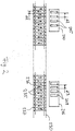
- FIG. 2 an alternative linear motor arrangement of a positioning system is shown.
- a passive stator 230 is shown, over whose length a large number of magnets 235 is arranged at a uniform distance d1.
- the poles of adjacent magnets 235 are each aligned in opposite directions, this is indicated by corresponding arrows 236.
- non-magnetic separating elements 237 are respectively arranged between the magnets 235.
- an active rotor 240 of a first carriage not shown, shown.
- four electromagnets 245 are arranged at a distance d2 in the present example.
- the distance d2 of the electromagnets 245 corresponds to 1.5 times the distance d1 of the magnets 235.
- the active rotor 240 can be moved by appropriate control of the electromagnets 245 along the passive stator 230, wherein the smallest increment of the movement of half the distance d1 of Magnets 235 corresponds.
- FIG. 2 shows FIG. 2 an active rotor 246 of a second carriage, not shown.
- the active rotor 246 also four electromagnets 248 are arranged, wherein a distance d3 of the electromagnets 248 is about 1.2 times the distance d1 of the magnets 235.
- the active rotor 246 can also be moved along the passive stator 230, wherein the smallest step size corresponds to 0.2 times the distance of the magnets 235 and thus is significantly smaller than the smallest step size of the active rotor 240.
- the second carriage can be positioned more accurately than the first carriage due to the smaller increment of the linear motor formed from the active rotor 246 and the passive stator 230.
- Positioning system shown two passive stators and provided for each slide two active runners.
- a positioning system described above can be freely combined with each other. For example, at the same time a higher motor force and a lower positioning accuracy can be provided for a carriage than for the other carriage. Similarly, a higher motor power and a higher positioning accuracy can also be selected for a slide.
- the passive stators 130,131 are designed separately from the guide rails 101,102
- the passive stators can be integrated in a non-illustrated variant of the invention in the guide rails. This makes it possible to achieve an even more compact design of the positioning system.
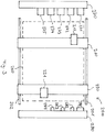
- FIG. 3 a material processing machine 200 is shown in a plan view.
- the material processing machine 200 in turn comprises two parallel guide rails 201,202 and two slides 210,220 which are movable along the guide rails 201,202.
- the functional units 211, 211 can be positioned within a working area 260 of the material processing machine 200 by displacing the carriages 210, 220 along the guide rails 201, 202 and by displacing the functional units 211, 211 along the carriages 210, 220.
- tool magazines 270, 280 are arranged outside the working area 260 of the processing machine 200.
- the first tool magazine 270 holds tools 271, 272, 273, 274, 275 which can be picked up by the functional unit 211 and used to machine a workpiece.
- the tools 271, 272, 273, 274, 275 may, for example, be focusing units for a laser beam with different focal lengths, and / or different mechanical cutting, drilling or milling tools.
- a Beam source for generating a laser beam and necessary beam deflections are not shown for reasons of clarity.
- the second tool magazine 280 holds tools 281, 282, 283, 284 which can be picked up by the second functional unit 221 and used to machine a workpiece.
- the tools 281, 282, 283, 284 may, for example, be a labeler, an inkjet printer, a marking pen and / or a scriber.
- the tool magazines can also be completely or partially dispensed with.
- one or both functional units can be firmly connected to a specific tool, which reduces the manufacturing and control costs of the material processing machine.
- the drive units of the slides 210, 220 correspond to the embodiments of FIGS. 1 and 2 be dimensioned differently.
- FIG. 4 another material processing machine 300 is shown. This corresponds in many respects to the material processing machine 200 of FIG. 2 , corresponding components are provided with a reference number increased by 100 and will not be described again in detail.
- the material processing machine 300 differs from the material processing machine 20 in that the carriage 310 is significantly longer than the width of the working area 360.
- two functional units 311, 312, which can be moved independently along the carriage 310, are arranged on the carriage 310. At least the functional unit 312 can thereby be moved beyond the boundary of the working area 360.
- the functional unit 312 can now be equipped, for example, with a gripping element to transport workpieces to be processed and / or finished from a conveyor 370 into the work area 360 or from the work area 360 onto the conveyor 370.
- the extended carriage 310 may also be provided with only a single functional unit.
- the conveyor 370 in addition to the work area 360 also a be provided simple supply table.
- a tool changing device not shown, may be arranged next to the work area 360.
- FIGS. 1 . 3 and 4 the working areas of the respective functional units are shown congruently, so that the functional units can simultaneously work on a workpiece arranged in the working area.
- the working areas of the individual functional units can be arranged one behind the other along the conveying path of a workpiece conveyor, whereby adjacent working areas can partially overlap.
- a clocked or continuously conveyed along the conveying path workpiece can then be processed sequentially by the individual functional units.
- the guide rails and / or the passive runners of the linear motors can be performed by juxtaposing individual components practically in any length, without the length of the components must be specially tailored to the position of the processing areas.
Landscapes
- Engineering & Computer Science (AREA)
- Mechanical Engineering (AREA)
- Physics & Mathematics (AREA)
- Chemical & Material Sciences (AREA)
- Combustion & Propulsion (AREA)
- Electromagnetism (AREA)
- Power Engineering (AREA)
- Linear Motors (AREA)
Applications Claiming Priority (1)
| Application Number | Priority Date | Filing Date | Title |
|---|---|---|---|
| DE102017129748.0A DE102017129748A1 (de) | 2017-12-13 | 2017-12-13 | Positionierungssystem und Materialbearbeitungsmaschine |
Publications (1)
| Publication Number | Publication Date |
|---|---|
| EP3498420A1 true EP3498420A1 (fr) | 2019-06-19 |
Family
ID=64664155
Family Applications (1)
| Application Number | Title | Priority Date | Filing Date |
|---|---|---|---|
| EP18211332.4A Withdrawn EP3498420A1 (fr) | 2017-12-13 | 2018-12-10 | Système de positionnement et machine de traitement du matériau |
Country Status (2)
| Country | Link |
|---|---|
| EP (1) | EP3498420A1 (fr) |
| DE (1) | DE102017129748A1 (fr) |
Cited By (1)
| Publication number | Priority date | Publication date | Assignee | Title |
|---|---|---|---|---|
| EP4371698A1 (fr) * | 2022-11-21 | 2024-05-22 | Sugino Machine Limited | Machine de traitement latéral et système de traitement latéral |
Families Citing this family (2)
| Publication number | Priority date | Publication date | Assignee | Title |
|---|---|---|---|---|
| JP7842058B2 (ja) * | 2023-05-15 | 2026-04-07 | 株式会社スギノマシン | 横型加工機 |
| DE102023118835A1 (de) * | 2023-07-17 | 2025-01-23 | Ersa Gmbh | Verfahreinheit zum Verfahren von Lötbaugruppen, Verfahrsystem, Lötstation |
Citations (4)
| Publication number | Priority date | Publication date | Assignee | Title |
|---|---|---|---|---|
| WO2006043173A2 (fr) * | 2004-10-22 | 2006-04-27 | Jobs S.P.A. | Machine-outil multiaxiale |
| DE60116992T2 (de) * | 2001-03-13 | 2006-09-21 | Jobs S.P.A. | Werkzeugmaschine mit mindestens zwei Bearbeitungseinheiten |
| DE102010024623A1 (de) * | 2010-06-22 | 2011-12-22 | Hesse & Knipps Gmbh | Präzisionswerkzeugmaschine |
| US20120062046A1 (en) * | 2010-09-13 | 2012-03-15 | Kabushiki Kaisha Yaskawa Denki | Multi-head linear motor with cores |
Family Cites Families (3)
| Publication number | Priority date | Publication date | Assignee | Title |
|---|---|---|---|---|
| DE4107530A1 (de) * | 1991-03-08 | 1992-09-17 | Intrasys Gmbh | Linearmotor i |
| DE102010000582A1 (de) * | 2010-02-26 | 2011-09-01 | Karl Storz Gmbh & Co. Kg | Linearmotor mit permanentmagnetischer Selbsthaltung |
| DE102015105043A1 (de) * | 2015-04-01 | 2016-10-06 | Samag Saalfelder Werkzeugmaschinen Gmbh | Bearbeitungsmaschine |
-
2017
- 2017-12-13 DE DE102017129748.0A patent/DE102017129748A1/de not_active Withdrawn
-
2018
- 2018-12-10 EP EP18211332.4A patent/EP3498420A1/fr not_active Withdrawn
Patent Citations (4)
| Publication number | Priority date | Publication date | Assignee | Title |
|---|---|---|---|---|
| DE60116992T2 (de) * | 2001-03-13 | 2006-09-21 | Jobs S.P.A. | Werkzeugmaschine mit mindestens zwei Bearbeitungseinheiten |
| WO2006043173A2 (fr) * | 2004-10-22 | 2006-04-27 | Jobs S.P.A. | Machine-outil multiaxiale |
| DE102010024623A1 (de) * | 2010-06-22 | 2011-12-22 | Hesse & Knipps Gmbh | Präzisionswerkzeugmaschine |
| US20120062046A1 (en) * | 2010-09-13 | 2012-03-15 | Kabushiki Kaisha Yaskawa Denki | Multi-head linear motor with cores |
Cited By (1)
| Publication number | Priority date | Publication date | Assignee | Title |
|---|---|---|---|---|
| EP4371698A1 (fr) * | 2022-11-21 | 2024-05-22 | Sugino Machine Limited | Machine de traitement latéral et système de traitement latéral |
Also Published As
| Publication number | Publication date |
|---|---|
| DE102017129748A1 (de) | 2019-06-13 |
Similar Documents
| Publication | Publication Date | Title |
|---|---|---|
| EP3547530B1 (fr) | Procédé de fonctionnement d'un dispositif de transport en forme de moteur linéaire à stator long | |
| EP3521219B1 (fr) | Dispositif de transport et procédé d'ajustement d'un dispositif de transport | |
| DE112016007247T5 (de) | Linearfördervorrichtung | |
| DE102007020495A1 (de) | Bogenstanz- und -prägemaschine und Verfahren zur Bogenausrichtung | |
| EP3482215B1 (fr) | Dispositif de pipettage comprenant un embout de pipetage déplaçable avec un écart entre les agrafes sur les rails | |
| DE2436900A1 (de) | Zweiachsige elektromagnetische positionierungseinrichtung | |
| DE102007020779B3 (de) | Bestückautomat zum Bestücken von elektrischen und/oder optischen Bauteilen auf Substrate | |
| EP3040296A1 (fr) | Systeme de transfert/montage modulaire | |
| EP3498420A1 (fr) | Système de positionnement et machine de traitement du matériau | |
| EP0967038B1 (fr) | Dispositif d' usinage de pièces par enlèvement de matière | |
| EP3031572A1 (fr) | Dispositif de changement d'outil destine a etre utilise dans un centre d'usinage et centre d'usinage destine a l'usinage mecanique d'une piece a usiner | |
| DE102007003295A1 (de) | Bürstenherstellungsmaschine | |
| EP1365886B1 (fr) | Table de serrage de piece | |
| EP1428613A1 (fr) | Dispositif de transport | |
| EP3028806A1 (fr) | Dispositif de traitement | |
| EP1002594A2 (fr) | Procédé et dipositif pour former une pièce | |
| DE102011085005B4 (de) | Biegemaschine, Biegeaggregat für eine Biegemaschine und Werkzeugträger für ein Biegeaggregat | |
| EP2008763B1 (fr) | Machine-outil dotée d'une unité fonctionnelle à moteur linéaire | |
| DE102007037886B4 (de) | Feldgeführter planarer Präzisionsantrieb mit einem luftgelagerten Läufer | |
| DE102006011974A1 (de) | Verfahren zum Transportieren von Werkstückträgern in einer Montagelinie, Werkstückträger und Montageeinheit | |
| DE202010000935U1 (de) | Vorrichtung zum Bearbeiten von Werkstücken | |
| DE102020117827B3 (de) | Förderanlage mit linearen Achsvorrichtungen | |
| DE19641879A1 (de) | Stellantrieb | |
| EP3335841A2 (fr) | Système de manipulateur pour systèmes de montage | |
| DE202007012353U1 (de) | Bogenstanz- und -prägemaschine |
Legal Events
| Date | Code | Title | Description |
|---|---|---|---|
| PUAI | Public reference made under article 153(3) epc to a published international application that has entered the european phase |
Free format text: ORIGINAL CODE: 0009012 |
|
| AK | Designated contracting states |
Kind code of ref document: A1 Designated state(s): AL AT BE BG CH CY CZ DE DK EE ES FI FR GB GR HR HU IE IS IT LI LT LU LV MC MK MT NL NO PL PT RO RS SE SI SK SM TR |
|
| AX | Request for extension of the european patent |
Extension state: BA ME |
|
| STAA | Information on the status of an ep patent application or granted ep patent |
Free format text: STATUS: THE APPLICATION IS DEEMED TO BE WITHDRAWN |
|
| 18D | Application deemed to be withdrawn |
Effective date: 20191220 |