EP3498622A1 - Emballage et ébauche pour la fabrication de l'emballage - Google Patents
Emballage et ébauche pour la fabrication de l'emballage Download PDFInfo
- Publication number
- EP3498622A1 EP3498622A1 EP18213550.9A EP18213550A EP3498622A1 EP 3498622 A1 EP3498622 A1 EP 3498622A1 EP 18213550 A EP18213550 A EP 18213550A EP 3498622 A1 EP3498622 A1 EP 3498622A1
- Authority
- EP
- European Patent Office
- Prior art keywords
- top part
- package
- wall
- crease
- crease line
- Prior art date
- Legal status (The legal status is an assumption and is not a legal conclusion. Google has not performed a legal analysis and makes no representation as to the accuracy of the status listed.)
- Withdrawn
Links
Images


Classifications
-
- B—PERFORMING OPERATIONS; TRANSPORTING
- B65—CONVEYING; PACKING; STORING; HANDLING THIN OR FILAMENTARY MATERIAL
- B65D—CONTAINERS FOR STORAGE OR TRANSPORT OF ARTICLES OR MATERIALS, e.g. BAGS, BARRELS, BOTTLES, BOXES, CANS, CARTONS, CRATES, DRUMS, JARS, TANKS, HOPPERS, FORWARDING CONTAINERS; ACCESSORIES, CLOSURES, OR FITTINGS THEREFOR; PACKAGING ELEMENTS; PACKAGES
- B65D5/00—Rigid or semi-rigid containers of polygonal cross-section, e.g. boxes, cartons or trays, formed by folding or erecting one or more blanks made of paper
- B65D5/42—Details of containers or of foldable or erectable container blanks
- B65D5/72—Contents-dispensing means
- B65D5/74—Spouts
- B65D5/746—Spouts formed separately from the container
-
- B—PERFORMING OPERATIONS; TRANSPORTING
- B65—CONVEYING; PACKING; STORING; HANDLING THIN OR FILAMENTARY MATERIAL
- B65D—CONTAINERS FOR STORAGE OR TRANSPORT OF ARTICLES OR MATERIALS, e.g. BAGS, BARRELS, BOTTLES, BOXES, CANS, CARTONS, CRATES, DRUMS, JARS, TANKS, HOPPERS, FORWARDING CONTAINERS; ACCESSORIES, CLOSURES, OR FITTINGS THEREFOR; PACKAGING ELEMENTS; PACKAGES
- B65D15/00—Containers having bodies formed by interconnecting or uniting two or more rigid, or substantially rigid, sections made of different materials
- B65D15/02—Containers having bodies formed by interconnecting or uniting two or more rigid, or substantially rigid, sections made of different materials of curved, or partially curved, cross-section, e.g. cans, drums
- B65D15/04—Containers having bodies formed by interconnecting or uniting two or more rigid, or substantially rigid, sections made of different materials of curved, or partially curved, cross-section, e.g. cans, drums with curved, or partially curved, walls made by winding or bending paper
- B65D15/08—Containers having bodies formed by interconnecting or uniting two or more rigid, or substantially rigid, sections made of different materials of curved, or partially curved, cross-section, e.g. cans, drums with curved, or partially curved, walls made by winding or bending paper with end walls made of plastics material
-
- B—PERFORMING OPERATIONS; TRANSPORTING
- B65—CONVEYING; PACKING; STORING; HANDLING THIN OR FILAMENTARY MATERIAL
- B65D—CONTAINERS FOR STORAGE OR TRANSPORT OF ARTICLES OR MATERIALS, e.g. BAGS, BARRELS, BOTTLES, BOXES, CANS, CARTONS, CRATES, DRUMS, JARS, TANKS, HOPPERS, FORWARDING CONTAINERS; ACCESSORIES, CLOSURES, OR FITTINGS THEREFOR; PACKAGING ELEMENTS; PACKAGES
- B65D3/00—Rigid or semi-rigid containers having bodies or peripheral walls of curved or partially-curved cross-section made by winding or bending paper without folding along defined lines
- B65D3/02—Rigid or semi-rigid containers having bodies or peripheral walls of curved or partially-curved cross-section made by winding or bending paper without folding along defined lines characterised by shape
- B65D3/08—Rigid or semi-rigid containers having bodies or peripheral walls of curved or partially-curved cross-section made by winding or bending paper without folding along defined lines characterised by shape having a cross-section of varying shape, e.g. circular merging into square or rectangular
Definitions
- the present solution relates to packages, and to blanks for manufacturing packages or parts of packages. More specifically, the present solution relates to a package, preferably for containing pourable liquid food products, for improving its ergonomic properties and its maneuverability.
- the package comprises a base part manufactured from a blank of packaging material and a top part.
- the base part and the top part are joined together to form the package.
- the base part comprises an essentially rectangular or square shaped bottom and four side walls extend from the bottom towards the top part.
- a first wall and an opposite second side wall each have a cross-section taken in a plane perpendicular to the bottom that transitions, from the bottom towards the top part, from an essentially planar shape to an essentially concave shape.
- the horizontal distance between the first crease line and second crease line along the third panel increases from a bottom crease towards a top edge wherein the horizontal distance between the third crease line and fourth crease line along the fourth panel increases from the bottom crease line towards the top edge.
- the package is advantageous as it provides improved ergonomic properties for example in the concave and the convex walls which provides natural and more comfortable grip zones.
- the package is thus made easier to use, and furthermore the shape of the package differentiates it from other packages.
- a third side wall and an opposite fourth side wall each have a cross-section taken in a plane being parallel with the bottom that transitions, from the bottom towards the top part, from an essentially planar shape to an essentially convex shape.
- the shape of the top part may preferably conform to the shape of the four side walls.
- the base part may be formed by a packaging material comprising one or more layers of material one of which may be a carton-based material, which provides a package that is environmentally friendly, inexpensive whilst still providing safe protection of the food product contained in the package.
- the top part may be formed by a plastic material, preferably by injection moulding of a thermoplastic material simultaneously while joining the top part to the base part.
- the blank may comprise a first and a second crease line defining a third panel forming the third wall of the package, and a third crease line and fourth crease line defining a fourth panel forming the fourth wall of the package.
- the second crease line and third crease line define a first panel forming the first wall of the package, and the first crease and fourth crease define a second panel forming the second wall of the package.
- Each crease line may correspond to a corresponding fold in the package.
- the horizontal distance between the second crease line and third crease line along the first panel may decrease from the bottom crease line toward a top edge, and the horizontal distance between the first crease line and fourth crease line along the second panel may decrease from a bottom crease line towards a top edge.
- the top part may comprise a first top part wall and a opposite second top part wall, the first and second top part walls having a convex shape that corresponds to the convex shape of the third and fourth walls of the base part respectively.
- the top part may further comprise a third top part wall arranged between the first and second top part walls and the third top part wall comprises an opening.
- the third top part wall conforms to the concave shape of the first and second wall of the base part.
- the convex and the concave shape of the base part thus extends to the top part where it transitions into an opening, the top part providing further structural rigidity to the base part and thus to the entire package.
- the top part may further comprise first and second curved edges which separates the first and second top part walls from the third top part wall.
- the first edge connecting essentially tangentially to the first and second crease line and the second edge connects essentially tangentially to the third and fourth crease lines.
- the top part and the base part may configured to be joined together in a joint comprising a weakening such that the top part may be removed from the base part.
- the removing of the top part from the base part is beneficial for recycling purposes and could also allow the user for to easier extract all the food stuff which may be difficult to extract from the opening.
- a blank for manufacturing a base part of a package is further provided.
- the blank is essentially rectangular in shape comprising a plurality of crease lines.
- the blank may comprise a bottom crease line defining transitions between the bottom and the side walls and the first, second, third and fourth crease lines stretches from the bottom crease line to a top edge.
- the first and second crease lines are straight crease lines being closer together toward the bottom crease line and further apart toward a top edge of the blank.
- the third and fourth crease lines are straight crease lines being closer together toward the bottom crease line and further apart toward the top edge of the blank.
- the second panel of the blank may comprise a first part and a second part being arranged on opposite sides of the blank and the two parts being configured to be joined together to form the second wall.
- the blank may comprise a fifth and a sixth crease line and the fifth crease line is arranged between the first and second crease lines, the sixth crease line is arranged between the third and fourth crease lines.
- the fifth and sixth crease lines are straight with extension essentially perpendicularly from the bottom crease line to the top edge.
- a package 1 is shown.
- the package 1 comprises a base part 2 and a top part 3 which are joined together to form the package 1.
- a fluid-tight joint 17 is formed at the transition between the top part 3 and the base part 2.
- a closure 4 in the top part 3 is shown, here in the shape of a cap which can be screwed on and off.
- other closures 4 are also feasible such as for instance peel-back lids, or tear-off membranes.
- the base part 2 is preferably made from a carton-based packaging material in the form of a blank 8.
- the carton-based packaging material may be a laminate material comprising several polymeric layers on both sides of a carton-based core layer.
- the carton-based material could be paper, paper board, carton or other similar fiber-based materials.
- the carton-based material is preferably the core material of the packaging laminate material and having a surface coating of thermoplastics on at least one of its two surfaces.
- a surface coating could be polyethylene film (PE film), but other materials could also be used in combination, such as for instance aluminum foil coated by a PE film on both sides, i.e. towards the interior of the package and away from the interior of the package..
- the packaging material may be cut to form sheets comprising individual blanks 8 which are then folded and joined together along a longitudinal seal to form the base part 2.
- the top part 3 is preferably of HDPE, high density polyethylene, however other thermoplastic polymer materials are of course also conceivable.
- the joint 17 between the top part 3 and the base part 2 could optionally be designed with a weakening along the joint 17, such as a perforation, to facilitate separation of the top part 3 and the base part 2 for instance for recycling purposes or for allowing a user to reach enclosed food product which is otherwise hard to extract through the opening 4.
- a weakening along the joint 17, such as a perforation to facilitate separation of the top part 3 and the base part 2 for instance for recycling purposes or for allowing a user to reach enclosed food product which is otherwise hard to extract through the opening 4.
- the base part 2 contains the major amount of food inside the package 1; the top part 3 provides the closure 4 and also stability and structural rigidity to the base part 2.
- the top part 3 may for example be manufactured by injection moulding, whereby the material for the top part 3 is injected into a mold, comprising an inner mould and an outer mould.
- the outer mould may have a conical shape over which the base part is pulled, while the inner mould may surround the outer mould and correspond in shape to the top part 3.
- At least the top edge 16 of the base part 2 is partially located on the cone forming the outer mould, such that after injection moulding the material in the top part 3 forms a bond in the joint 17 with material of the base part 2.
- the material in the top part 3 hardens it will also, as mentioned, contribute to maintaining the shape of the walls 5a, 5b, 6a, 6b of the base part 2.
- the base part 2 comprises a bottom 7, which is formed by means of folding along a plurality of crease lines in a conventional manner which is to be considered well known in the art and will thus not be explained in further detail.
- the bottom 7 may be rectangular in shape, while more specifically a square shape is envisioned in one embodiment. Other shapes are however also feasible, such as more oblong rectangular shapes or D-shaped bottoms.
- the base part 2 as shown in Fig. 2 , comprises four side walls 5a, 5b, 6a, 6b which extend from the bottom 7 to the top edge 16 of the base part 2.
- the top edge 16 is the part of the base part 2 which is configured to be joined to the top part 3 by injection moulding or some other process.
- a first side wall 5a and a second side wall 5b are arranged on opposite sides of the base part 2 and are both configured such that they transition from the bottom 7 to the top edge 16 from an essentially planar shape close to the bottom 7 to an increasingly concave shape towards the top edge 16.
- the concave shape is defined as seen in a cross-sectional plane through the side walls 5a, 5b, and where the cross-sectional plane is orthogonal the bottom 7.
- the third and fourth side walls 6a, 6b are also arranged on opposite sides of the base part 2 and are both configured such that they transition from the bottom 7 to the top edge 16 from an essentially planar shape close to the bottom 7 to an increasingly convex shape towards the top edge 16.
- the convex shape is defined as seen in cross-sectional plane orthogonal to the bottom 7 through the side walls 6a, 6b.
- the concave shape of the first and second walls 5a, 5b in combination with the convex shape of the third and fourth walls 6a, 6b provides a package 1 with improved ergonomics.
- the convex walls 6a, 6b are configured for fitting comfortably against the palm of a consumer while the concave walls 5a, 5b are configured such that they form gripping zones for the fingers of the user. Also, by the provision of the concave and the convex walls 5a, 5b, 6a, 6b, a consumer will be able to see for instance product names or logos on the package from further distances and/or more shallow angles.
- the base part 2 is formed from a blank 8, as is shown in Fig. 5 .
- the blank 8 comprises crease lines 9-15 which may be formed into corresponding folds or edges in the base part 2 when raising the base part 2 of the package 1.
- a first and a second crease line 9, 11 define a third panel 6'a corresponding to the third wall 6a of the folded base part 2.
- a third and fourth crease line 12, 14 define a fourth panel 6'b corresponding to the fourth wall 6b of the folded base part 2. That is, the third panel 6'a extends from the bottom 7 to the top edge 16 between the first and second crease lines 9, 11. This is analogous for all the panels 5'a, 5'b, 6'a, 6'b of the blank 8.
- the horizontal distance between the first and second crease lines 9, 11 along the third panel 6'a increases from a bottom crease line 15 towards the top edge 16. That is, a horizontal line across the convex surface of the third wall 6a from the first crease line 9 to the second crease line 11 will become progressively longer from the bottom 7 approaching the top edge of the base part 2.
- the horizontal distance between the third and fourth crease lines 12, 14 along the fourth panel 6'b also increases from the bottom crease line 15 and towards the top edge 16, preferably such that the width between the respective crease lines 9, 11, 12, 14 measured along the surface of the third and fourth wall 6a, 6b on a certain height above the bottom 7 is essentially the same.
- the first panel 5'a corresponding to the first wall 5a of the base part 2, is defined by the second and third crease lines 11, 12.
- the first and fourth crease lines 9, 14 define the second panel 5'b, corresponding to the second wall 5b of the base part 2.
- the horizontal distance between the second and third crease lines 11, 12 along the first wall 5a decreases from a bottom crease line 15 towards the top edge 16 as does the horizontal distance between the first and fourth crease lines 9, 14 along the second wall 5b from the bottom crease line 15 towards the top edge 16.
- the width between the respective crease lines defining each wall measured along the surface of each concave wall 5a, 5b is essentially the same for a given height above the bottom 7.
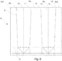
- FIGs. 5 and 6 are two embodiments of a blank 8 shown.
- a blank 8 is a well-known item to the skilled person, and should be construed as a piece of packaging material configured to be folded into packages or parts of packages such as base parts 2.
- the blank 8 comprises crease lines 9-15, which facilitate and serve as templates for the folding the blank 8 into a base part 2.
- the blank 8 is preferably of a rectangular shape. It is to be understood that while only single blanks 8 are shown, blanks 8 can be provided as a web of continuous packaging material, whereby consecutive blanks are arranged side by side or in any other orientation on the web.
- the blank 8 comprises a bottom crease line 15 defining transitions between the bottom 7 and the side walls 5a, 5b, 6a, 6b. As can be seen in Figs. 5 and 6 , a plurality of crease lines are shown below the bottom crease 15. These are present to facilitate the folding of the bottom 7 of the base part 2, and as mentioned above, are considered to be known by a skilled person and will thus not be explained in further detail.
- the first, second, third and fourth crease lines 9, 11, 12, 14 stretches in an essentially straight line from the bottom crease line 15 to a top edge 16 of the blank 8.
- the first and second crease lines 9, 11, and the third and fourth crease lines 12, 14 respectively, are arranged such that they are closer together toward the bottom crease line 15 and further apart toward a top edge 16 of the blank 8.
- the third wall 6a which extends between the first and second crease lines 9, 11 and the fourth wall 6b which extends between the third and fourth crease lines 12, 14 both taper towards the bottom crease line 15.
- the opposite relationship is found for the first and second walls 5a, 5b which extend between the second and third crease lines 11, 12 and between the first and fourth crease lines 9, 14 respectively, which tapers from the bottom crease line 15 towards the top edge 16.
- the second panel 5'b may be divided into a first part 5b1 and a second part 5b2 on separate sides of the blank 8 and being configured to be joined together to form the second wall 5b.
- each of the walls 5a, 5b, 6a, 6b could be divided into two parts in a similar manner.
- the blank 8 may comprise a fifth and a sixth crease line 10, 13.
- the fifth crease line 10 is preferably arranged at the center between the first and second crease lines 9, 11 and the sixth crease line 13 is preferably arranged at the center between the third and fourth crease lines 12, 14.
- the fifth and sixth crease lines 10, 13 are straight crease lines with extension essentially orthogonally from the bottom crease line 15 to the top edge 16. The fifth and sixth crease lines 10, 13 thus divide the third wall 6a and the fourth wall 6b longitudinally in two approximately equally sized parts.
- the top part 3 may comprise top part walls 3a, 3b, 3c which conform to the shape of the base part 2.
- the first and second opposite top part walls 3a, 3b thus have convex shapes that essentially correspond to the convex shape of the third and fourth walls 6a, 6b of the base part 2 by visually forming one continuous surface.
- the third top part wall 3c is arranged between the first and second top part walls 3a, 3b and comprises the closure 4 in the form of a cap 4 mounted onto a neck of the top part forming the opening of the top part..
- the third top part wall 3c conforms or transitions gradually towards the joint 17 to the concave shape of the first and second wall 5a, 5b of the base part 2, thus also visually forming one continuous surface.
- the top part 3 may further comprise first and second curved edges 3d, 3e which separate the first and second top part walls 3a, 3b from the third top part wall 3c.
- the first edge 3d connects essentially tangentially to the first and second crease line 9, 11 and the second edge 3e connects essentially tangentially to the third and fourth crease line 12, 14.
- the first and second edges 3d, 3e thus provide a shoulder like shape to the package 1 and more specifically the top part 3.
Landscapes
- Engineering & Computer Science (AREA)
- Mechanical Engineering (AREA)
- Cartons (AREA)
Applications Claiming Priority (1)
| Application Number | Priority Date | Filing Date | Title |
|---|---|---|---|
| EP17208132 | 2017-12-18 |
Publications (1)
| Publication Number | Publication Date |
|---|---|
| EP3498622A1 true EP3498622A1 (fr) | 2019-06-19 |
Family
ID=60673833
Family Applications (1)
| Application Number | Title | Priority Date | Filing Date |
|---|---|---|---|
| EP18213550.9A Withdrawn EP3498622A1 (fr) | 2017-12-18 | 2018-12-18 | Emballage et ébauche pour la fabrication de l'emballage |
Country Status (2)
| Country | Link |
|---|---|
| EP (1) | EP3498622A1 (fr) |
| WO (1) | WO2019121724A1 (fr) |
Citations (4)
| Publication number | Priority date | Publication date | Assignee | Title |
|---|---|---|---|---|
| EP0443369A2 (fr) * | 1990-02-20 | 1991-08-28 | Tetra Laval Holdings & Finance SA | Emballage pour produits fluides avec encoches de préhension et procédé pour sa fabrication |
| JPH06247435A (ja) * | 1993-02-24 | 1994-09-06 | Dainippon Printing Co Ltd | 飲料容器 |
| USD448285S1 (en) * | 2000-04-06 | 2001-09-25 | Tetra Laval Holdings & Finance S.A. | Packaging container |
| WO2011120857A1 (fr) * | 2010-03-31 | 2011-10-06 | Tetra Laval Holdings & Finance S.A. | Emballage et matériau pour la formation dudit emballage |
-
2018
- 2018-12-18 WO PCT/EP2018/085556 patent/WO2019121724A1/fr not_active Ceased
- 2018-12-18 EP EP18213550.9A patent/EP3498622A1/fr not_active Withdrawn
Patent Citations (4)
| Publication number | Priority date | Publication date | Assignee | Title |
|---|---|---|---|---|
| EP0443369A2 (fr) * | 1990-02-20 | 1991-08-28 | Tetra Laval Holdings & Finance SA | Emballage pour produits fluides avec encoches de préhension et procédé pour sa fabrication |
| JPH06247435A (ja) * | 1993-02-24 | 1994-09-06 | Dainippon Printing Co Ltd | 飲料容器 |
| USD448285S1 (en) * | 2000-04-06 | 2001-09-25 | Tetra Laval Holdings & Finance S.A. | Packaging container |
| WO2011120857A1 (fr) * | 2010-03-31 | 2011-10-06 | Tetra Laval Holdings & Finance S.A. | Emballage et matériau pour la formation dudit emballage |
Also Published As
| Publication number | Publication date |
|---|---|
| WO2019121724A1 (fr) | 2019-06-27 |
Similar Documents
| Publication | Publication Date | Title |
|---|---|---|
| CN107264910B (zh) | 复合材料包装件、包装件层压制品和复合材料包装件的包装套筒坯料 | |
| JP7321238B2 (ja) | マルチパーツコンテナのための相互接続手段 | |
| EP2621817B1 (fr) | Contenant d'emballage et découpe utilisable dans la production d'un tel contenant d'emballage | |
| JP5831172B2 (ja) | ブランクおよびそれを用いた液体用紙容器 | |
| US20190337666A1 (en) | Sleeve Blank, Package Sleeve, Package and Method for Manufacturing a Sleeve Blank, a Package Sleeve and a Package | |
| CA2961959A1 (fr) | Cannelure en matiere plastique | |
| JP2017202849A (ja) | ゲーベルトップ型包装容器 | |
| US10815025B2 (en) | Gable top with spout closure | |
| CN107787293B (zh) | 具有抓握支撑表面的包装容器 | |
| JP2014506549A (ja) | 液体食品を保存するためのパッケージ、該パッケージの一部を形成するブランク、ブランクのリール、及び繊維系パッケージング材料に触覚パターンを形成する方法 | |
| WO2018122743A1 (fr) | Récipient pour produits alimentaires pouvant être versés | |
| EP3498622A1 (fr) | Emballage et ébauche pour la fabrication de l'emballage | |
| EP2552791A1 (fr) | Emballage et matériau pour la formation dudit emballage | |
| CN107364624B (zh) | 屋顶式包装容器 | |
| US20210094723A1 (en) | A package | |
| EP3498621A1 (fr) | Emballage et flan permettant de former une partie basale d'un emballage | |
| US10507963B2 (en) | Resealable opening device and package comprising such an opening device | |
| CN103786973A (zh) | 用于包装食品的包装材料 | |
| EP2371722B1 (fr) | Emballage et matériau de formation de cet emballage | |
| CN206336525U (zh) | 屋顶式包装容器 | |
| JP6911362B2 (ja) | 注出口を備えたパウチ | |
| JP6922201B2 (ja) | 包装容器及び包装容器用ブランク | |
| JPH044218B2 (fr) | ||
| WO2019127586A1 (fr) | Découpe pour la fabrication de contenant d'emballage de liquide et contenant d'emballage | |
| WO2019127584A1 (fr) | Découpe pour la fabrication d'un contenant d'emballage de liquide et contenant d'emballage |
Legal Events
| Date | Code | Title | Description |
|---|---|---|---|
| STAA | Information on the status of an ep patent application or granted ep patent |
Free format text: STATUS: UNKNOWN |
|
| PUAI | Public reference made under article 153(3) epc to a published international application that has entered the european phase |
Free format text: ORIGINAL CODE: 0009012 |
|
| STAA | Information on the status of an ep patent application or granted ep patent |
Free format text: STATUS: THE APPLICATION HAS BEEN PUBLISHED |
|
| AK | Designated contracting states |
Kind code of ref document: A1 Designated state(s): AL AT BE BG CH CY CZ DE DK EE ES FI FR GB GR HR HU IE IS IT LI LT LU LV MC MK MT NL NO PL PT RO RS SE SI SK SM TR |
|
| AX | Request for extension of the european patent |
Extension state: BA ME |
|
| STAA | Information on the status of an ep patent application or granted ep patent |
Free format text: STATUS: REQUEST FOR EXAMINATION WAS MADE |
|
| 17P | Request for examination filed |
Effective date: 20191219 |
|
| RBV | Designated contracting states (corrected) |
Designated state(s): AL AT BE BG CH CY CZ DE DK EE ES FI FR GB GR HR HU IE IS IT LI LT LU LV MC MK MT NL NO PL PT RO RS SE SI SK SM TR |
|
| STAA | Information on the status of an ep patent application or granted ep patent |
Free format text: STATUS: THE APPLICATION IS DEEMED TO BE WITHDRAWN |
|
| 18D | Application deemed to be withdrawn |
Effective date: 20191220 |