EP3498639B1 - Vorrichtung zum zusammenführen von zwei in unterschiedlichen höhen angeordneten stückgutströmen - Google Patents
Vorrichtung zum zusammenführen von zwei in unterschiedlichen höhen angeordneten stückgutströmen Download PDFInfo
- Publication number
- EP3498639B1 EP3498639B1 EP17207274.6A EP17207274A EP3498639B1 EP 3498639 B1 EP3498639 B1 EP 3498639B1 EP 17207274 A EP17207274 A EP 17207274A EP 3498639 B1 EP3498639 B1 EP 3498639B1
- Authority
- EP
- European Patent Office
- Prior art keywords
- conveying surface
- vertical plane
- width
- conveying
- side panel
- Prior art date
- Legal status (The legal status is an assumption and is not a legal conclusion. Google has not performed a legal analysis and makes no representation as to the accuracy of the status listed.)
- Active
Links
Images

Classifications
-
- B—PERFORMING OPERATIONS; TRANSPORTING
- B65—CONVEYING; PACKING; STORING; HANDLING THIN OR FILAMENTARY MATERIAL
- B65G—TRANSPORT OR STORAGE DEVICES, e.g. CONVEYORS FOR LOADING OR TIPPING, SHOP CONVEYOR SYSTEMS OR PNEUMATIC TUBE CONVEYORS
- B65G11/00—Chutes
- B65G11/08—Chutes with discontinuous guiding surfaces, e.g. arranged in zigzag or cascade formation
- B65G11/083—Chutes with discontinuous guiding surfaces, e.g. arranged in zigzag or cascade formation for bulk
-
- B—PERFORMING OPERATIONS; TRANSPORTING
- B65—CONVEYING; PACKING; STORING; HANDLING THIN OR FILAMENTARY MATERIAL
- B65G—TRANSPORT OR STORAGE DEVICES, e.g. CONVEYORS FOR LOADING OR TIPPING, SHOP CONVEYOR SYSTEMS OR PNEUMATIC TUBE CONVEYORS
- B65G47/00—Article or material-handling devices associated with conveyors; Methods employing such devices
- B65G47/52—Devices for transferring articles or materials between conveyors i.e. discharging or feeding devices
- B65G47/66—Fixed platforms or combs, e.g. bridges between conveyors
-
- B—PERFORMING OPERATIONS; TRANSPORTING
- B65—CONVEYING; PACKING; STORING; HANDLING THIN OR FILAMENTARY MATERIAL
- B65G—TRANSPORT OR STORAGE DEVICES, e.g. CONVEYORS FOR LOADING OR TIPPING, SHOP CONVEYOR SYSTEMS OR PNEUMATIC TUBE CONVEYORS
- B65G47/00—Article or material-handling devices associated with conveyors; Methods employing such devices
- B65G47/52—Devices for transferring articles or materials between conveyors i.e. discharging or feeding devices
- B65G47/68—Devices for transferring articles or materials between conveyors i.e. discharging or feeding devices adapted to receive articles arriving in one layer from one conveyor lane and to transfer them in individual layers to more than one conveyor lane or to one broader conveyor lane, or vice versa, e.g. combining the flows of articles conveyed by more than one conveyor
- B65G47/681—Devices for transferring articles or materials between conveyors i.e. discharging or feeding devices adapted to receive articles arriving in one layer from one conveyor lane and to transfer them in individual layers to more than one conveyor lane or to one broader conveyor lane, or vice versa, e.g. combining the flows of articles conveyed by more than one conveyor from distinct, separate conveyor lanes
-
- B—PERFORMING OPERATIONS; TRANSPORTING
- B65—CONVEYING; PACKING; STORING; HANDLING THIN OR FILAMENTARY MATERIAL
- B65G—TRANSPORT OR STORAGE DEVICES, e.g. CONVEYORS FOR LOADING OR TIPPING, SHOP CONVEYOR SYSTEMS OR PNEUMATIC TUBE CONVEYORS
- B65G11/00—Chutes
- B65G11/18—Supports or mountings
- B65G11/186—Supports or mountings for bulk
-
- B—PERFORMING OPERATIONS; TRANSPORTING
- B65—CONVEYING; PACKING; STORING; HANDLING THIN OR FILAMENTARY MATERIAL
- B65G—TRANSPORT OR STORAGE DEVICES, e.g. CONVEYORS FOR LOADING OR TIPPING, SHOP CONVEYOR SYSTEMS OR PNEUMATIC TUBE CONVEYORS
- B65G47/00—Article or material-handling devices associated with conveyors; Methods employing such devices
- B65G47/52—Devices for transferring articles or materials between conveyors i.e. discharging or feeding devices
- B65G47/68—Devices for transferring articles or materials between conveyors i.e. discharging or feeding devices adapted to receive articles arriving in one layer from one conveyor lane and to transfer them in individual layers to more than one conveyor lane or to one broader conveyor lane, or vice versa, e.g. combining the flows of articles conveyed by more than one conveyor
- B65G2047/685—Devices for preventing jamming in converging flows
Definitions
- the invention relates to a device for merging two piece goods flows arranged at different heights or vertically one above the other, with an upper conveying channel for taking over piece goods parts from an upper piece goods flow and a lower conveying channel for taking over piece goods parts from a lower piece goods flow.
- the device for merging can be an end point and the general cargo flows can be conveying devices or sorting devices, a sorting system provided with such an end point consisting of at least one upper sorting device and one lower sorting device.
- the sorting devices preferably have conveying directions which are opposite to one another. It would also be conceivable that the funding directions match.
- the conveying channels of which extend between a first vertical plane and a parallel second vertical plane, the mutual distance of which corresponds to an overall channel width of the device there is the difficulty of bringing the conveying channels together in a favorable manner in order to divide the piece goods from the piece goods stream downstream to one To direct discharge channel.
- the conveying channels are brought together next to one another, each conveying channel having a width which corresponds to half the total channel width. In such an embodiment, it can happen relatively easily that general cargo parts, the largest dimension of which is greater than half the total channel width, get jammed in the course of the discharge in a conveyor channel, which can lead to considerable malfunctions.
- the US 5,361,889 A. discloses a device for merging at least two piece goods streams arranged at different heights, with an upper conveying channel for taking over piece goods parts from an upper piece goods flow, and a lower conveying channel for taking over piece goods parts from a lower piece goods flow, the conveying channels being between a first vertical plane and a parallel second vertical plane, the mutual distance of which corresponds to a total channel width of the device, the upper conveyor channel having a first conveyor surface between a first side wall and a second side wall, and a second conveyor surface which adjoins a third side wall downstream of the first conveyor surface , wherein the lower conveyor channel has a third conveyor surface which has a width which is greater than half the total channel width and is delimited by a fourth side wall and a fifth side wall.
- the object of the invention is to provide a device for merging at least two at different heights or one above the other To provide general cargo flows in which the risk of jamming of general cargo parts in a conveying channel is reduced.
- the second conveying surface preferably adjoins the first conveying surface without gaps and with an equal, larger or smaller slope with respect to the first conveying surface.
- the width of the second conveying surface is preferably constant over its length.
- the second conveying surface has a smaller width than half the total channel width, it is possible to convey general cargo parts whose width is greater than that of the second conveying surface and which can be up to a dimension corresponding to the total channel width, since the second conveying surface is at a distance of or the side edge running parallel to the first vertical plane ends freely and larger piece goods can survive beyond this side edge. Since the lower conveying channel or the third conveying surface has a width that is greater than half the total channel width, piece goods whose width is greater than half the total channel width can also be transported in this channel, so that jamming is effectively counteracted.
- the second side wall can run completely in the second vertical plane, it being possible for the first conveying surface to have a downstream end section which is arranged between the second side wall and the side edge of the second conveying surface and which is at a vertical distance above the lower conveying channel or the third conveying surface is arranged.
- General cargo parts which in individual cases, despite their original conveying speed in the bulk cargo flows, do not reach the first side wall and the second conveying surface during the delivery process, can then fall from the downstream end section of the first conveying surface onto the lower conveying channel or onto the third conveying surface.
- the second side wall extends at an acute angle to the second vertical plane and extends from the second vertical plane in the direction of the second conveying surface.
- This variant has the advantage that the incoming general cargo parts are routed to the second conveying surface in any case. there is a certain possibility of jamming individual parts.
- the first conveying surface can have a downstream end section arranged between the second side wall and the side edge, which is arranged at a vertical distance above the lower conveying channel or the third conveying surface.
- the fifth side wall can extend from an initial position located in the first vertical plane to an end position located vertically below the side edge of the second conveying surface, for example in a straight line or in an arc shape.
- the fifth side wall can have an transition section running at an acute angle to the first vertical plane and an adjoining guide section running parallel to the first vertical plane, the distance from the first vertical plane corresponding to the width of the second conveying surface.
- the first conveying surface is arranged horizontally, ie perpendicular to the first and second vertical planes. It can further be provided that the second conveying surface is arranged so as to drop obliquely either perpendicular to the first vertical plane or at an angle to the first vertical plane or third side wall.
- a partial area of the first conveying surface which, starting from the first vertical plane or first side wall, has the same width as the second conveying surface, either perpendicular to the first vertical plane or first sidewall or at an angle obliquely to the first vertical plane or first sidewall is arranged sloping.
- the angle mentioned can be, for example, between 5 ° and 30 °, so that a type of conveyor trough for piece goods parts is formed.
- the lower conveying surface is arranged perpendicular to the vertical planes.
- the discharge channel preferably has a fourth conveying surface that runs horizontally or perpendicularly to the vertical planes.
- a downstream end section of the second conveying surface is preferably arranged at the same height as an downstream end section of the third conveying surface in order to ensure a problem-free transition of the piece goods parts to the discharge channel or the fourth conveying surface.
- the two end sections are expediently in the same longitudinal position, so that the fourth conveying surface can connect seamlessly to the second and third conveying surfaces.
- the first conveying surface and / or, if present, the partial area of the first conveying surface and / or the second conveying surface and / or the third lower conveying surface and / or the fourth conveying surface can each be used as a sliding surface, sliding plate or slide, driven or passive roller conveyor or belt conveyor. or belt conveyor.
- first conveying surface if present, the partial area of the first conveying surface and the second conveying surface have a slope.
- the third conveying surface can have a slope or be arranged horizontally.
- the device for merging piece goods streams can comprise at least one upper sorting device and at least one lower sorting device, the piece goods flows being designed as sorting devices and the sorting devices being able to be vertically one above the other or at a horizontal distance from one another.
- the sorting devices can be designed as cross belt sorters.
- sorting devices can be operated in the same or opposite conveying directions.
- the vertical planes are arranged perpendicular to the conveying directions.
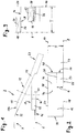
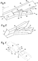
- a first embodiment of the invention is based on 1 to 6 explained.
- the device according to the invention in the form of an end point 2 serves to take over piece goods parts from at least two piece goods flows arranged at different heights or also vertically one above the other Fig. 1 denoted by 4 and 6 and are designed, for example, as sorting devices.
- any conveyor technology or device for generating piece goods streams could be present, with which individual piece goods parts are conveyed in two lanes, which are to be combined into a single piece of goods to be conveyed.
- an upper sorting device 4 is arranged vertically above a lower sorting device 6, the conveying directions of which are horizontal, perpendicular to the plane of the drawing.
- the sorting devices can be designed, for example, as cross belt sorters, with a load-carrying device drivable transversely to the conveying direction, with which individual piece goods parts can be discharged horizontally and transversely to the conveying direction on the end of each carriage or sorter element.
- a large number of end points viewed in the conveying direction, are arranged one behind the other next to the sorting devices, the sorting process being carried out by selecting a specific end point.
- One terminal each and in particular the one in Fig. 1 illustrated terminal 2 is between two spaced vertical planes, a first vertical plane 8 and one at a distance T, which is also called Total channel width of the end point is referred to, the second vertical plane 10 located therefrom.
- the vertical planes 8, 10 are preferably arranged perpendicular to the conveying directions of the sorting devices 4, 6.
- the terminal 2 has an upper conveying channel 12 for taking over general cargo parts from the upper sorting device 4 and a lower conveying channel 14 for taking over general cargo parts from the lower sorting device 6.
- the upper conveying channel 12 has a first conveying surface 16 which extends from one in the first vertical plane 8 extending first side wall 18 and is limited by a second side wall 20 extending in the second vertical plane 10.
- the upper conveying channel 12 has, after the first conveying surface 16, a second conveying surface 24 which is delimited by a third side wall 26 running in the first vertical plane 8.
- the third side wall 26 can directly adjoin the first side wall 18.
- the second conveying surface 24 has a side edge 28 at which it ends freely.
- the side edge 28 runs parallel to the first connection plane 8 and has a distance a from it which corresponds to a width of the second conveying surface 24 and is less than half the total channel width T.
- the first conveying surface 16 has a width which corresponds to and has the total channel width T.
- between the second side wall 20 and the side edge 28 of the second conveying surface 24 has a downstream end section 30 which ends at a vertical distance above the lower conveying channel 14.
- the first side wall 18 and the second side wall 20 each end with upstream end sections 18a, 20a at a distance from an upstream end section 32 of the first conveying surface 16, in order to make it possible for piece goods delivered by the upper sorting device 4 to pass through a curved trajectory transversely to the conveying direction , which is useful at higher conveying and discharge speeds.
- the upstream end section 32 of the first conveying surface 16 is arranged directly adjacent to the upper sorting device 6 when the end point is used, as the side view of FIG Fig. 1 shows.
- the lower conveyor channel 14 has a third conveyor surface 36 which is delimited by a fourth side wall 38 and a fifth side wall 40 running in the second vertical plane 10.
- the fifth side wall 40 extends from an initial position located in the first vertical plane 8 to an end position located vertically below the side edge 28 of the second conveying surface 24, with a transition section 42 running at an acute angle to the first vertical plane 8 and an adjoining section 42 has parallel to the first vertical plane 8 guide portion 44, the distance from the first vertical plane corresponds to the width of the second conveying surface 24.
- the fourth sidewall 38 and the fifth sidewall 40 start spaced from an upstream end portion 46 of the third conveyor surface 36 that is adjacent to the lower sorter 6 as well Fig. 1 shows, as explained above with regard to the first and second side wall of the first conveying surface 16, to enable a favorable transfer of the piece goods parts.
- a downstream end section 48 of the third conveying surface 36 is located at the same height and directly adjacent to a downstream end section 50 of the second conveying surface 24, with an outflow channel 52 with a fourth conveying surface 54 adjoining the second conveying surface 24 and the third conveying surface 36 or their downstream side End sections 48, 50 connects.
- the fourth conveying surface 54 extends over the full width or the total channel width T of the end point 2, between the vertical planes 8, 10 and between side walls running in these, which seamlessly adjoin the third and fourth side walls 26, 38 of the second and third conveying surfaces 24, 36 can connect.
- Fig. 3 explains in a sectional view how general cargo parts, which can be wider than half the width or half the total channel width of the end station 2, can be discharged from the sorting devices on the upper conveyor channel and the lower conveyor channel without interference.
- Fig. 3 shows in the upper part of the illustration a piece goods part 60, which is on the second conveyor surface 24 in abutment against the third side wall 26, whereby it projects laterally due to its width over the second conveyor surface 24 and the side edge 28 thereof. Accordingly shows Fig. 3 in the lower part of the illustration, a piece goods part 62 on the third conveying surface 36, the width or the mutual spacing of the fourth and fifth side walls 38, 40 being greater than half the total channel width T.
- Fig. 3 shows in the upper part of the illustration a piece goods part 60, which is on the second conveyor surface 24 in abutment against the third side wall 26, whereby it projects laterally due to its width over the second conveyor surface 24 and the side edge 28 thereof.
- Fig. 3 in the lower part of the illustration,
- FIG. 3 also shows that the side edge 28 of the second conveyor surface 24 is vertically above the fourth side wall 38 of the third conveyor surface 36.
- the top view according to Fig. 2 also clearly shows the width ratios of the first conveying surface 16, the second conveying surface 24 and the third conveying surface 36, and of the discharge duct 52 with the fourth conveying surface 54.
- FIG. 9 shows exemplary an arrangement in which the second conveying surface 24 ′ and the partial region 16 ′ of the first conveying surface run at an angle of approximately 15 ° with respect to the first conveying surface 16 in the direction of the first vertical plane 8.
- first side wall 18 'and the third side wall 26' can also be arranged at an angle to the first vertical plane 8, so that they run at right angles to the obliquely running second conveying surface 24 'and the partial region 16' of the first conveying surface 16.
- Fig. 9 shows, general cargo parts, which are often cuboid, can then be promoted particularly cheap.
Landscapes
- Engineering & Computer Science (AREA)
- Mechanical Engineering (AREA)
- Branching, Merging, And Special Transfer Between Conveyors (AREA)
- Attitude Control For Articles On Conveyors (AREA)
- Discharge Of Articles From Conveyors (AREA)
Priority Applications (3)
| Application Number | Priority Date | Filing Date | Title |
|---|---|---|---|
| PL17207274T PL3498639T3 (pl) | 2017-12-14 | 2017-12-14 | Urządzenie do łączenia dwóch strumieni drobnicy usytuowanych na różnych wysokościach |
| EP17207274.6A EP3498639B1 (de) | 2017-12-14 | 2017-12-14 | Vorrichtung zum zusammenführen von zwei in unterschiedlichen höhen angeordneten stückgutströmen |
| US16/201,466 US10377570B2 (en) | 2017-12-14 | 2018-11-27 | Device for merging two piece goods streams arranged at different heights |
Applications Claiming Priority (1)
| Application Number | Priority Date | Filing Date | Title |
|---|---|---|---|
| EP17207274.6A EP3498639B1 (de) | 2017-12-14 | 2017-12-14 | Vorrichtung zum zusammenführen von zwei in unterschiedlichen höhen angeordneten stückgutströmen |
Publications (2)
| Publication Number | Publication Date |
|---|---|
| EP3498639A1 EP3498639A1 (de) | 2019-06-19 |
| EP3498639B1 true EP3498639B1 (de) | 2020-05-20 |
Family
ID=60781532
Family Applications (1)
| Application Number | Title | Priority Date | Filing Date |
|---|---|---|---|
| EP17207274.6A Active EP3498639B1 (de) | 2017-12-14 | 2017-12-14 | Vorrichtung zum zusammenführen von zwei in unterschiedlichen höhen angeordneten stückgutströmen |
Country Status (3)
| Country | Link |
|---|---|
| US (1) | US10377570B2 (pl) |
| EP (1) | EP3498639B1 (pl) |
| PL (1) | PL3498639T3 (pl) |
Families Citing this family (3)
| Publication number | Priority date | Publication date | Assignee | Title |
|---|---|---|---|---|
| JP6629380B2 (ja) * | 2018-04-11 | 2020-01-15 | セキ工業株式会社 | 部品整送装置 |
| CA3220133A1 (en) * | 2021-05-31 | 2022-12-08 | Korber Supply Chain Logistics Gmbh | Tapering of a conveyor flow of piece goods |
| CN114453323B (zh) * | 2022-03-11 | 2023-05-16 | 南京享利达模具有限公司 | 自动进料带烘干干压水清洗机 |
Family Cites Families (17)
| Publication number | Priority date | Publication date | Assignee | Title |
|---|---|---|---|---|
| US1969276A (en) * | 1930-10-24 | 1934-08-07 | Pevear Chase Keith | Merchandise handling system |
| US3221857A (en) * | 1964-07-09 | 1965-12-07 | Holstein & Kappert Maschf | Apparatus for orienting bottle caps and the like |
| DE1975576U (de) * | 1967-08-28 | 1967-12-21 | Herkules Papiersackfabriken Br | Vorrichtung zur herstellung von saecken aus papier, kunststoff od. dgl. |
| US3612268A (en) * | 1970-04-15 | 1971-10-12 | Dynasort Corp | Silverware orienting means |
| GB1448744A (en) * | 1973-11-05 | 1976-09-08 | Danepak Ltd | Conveyors |
| US4033441A (en) * | 1975-06-16 | 1977-07-05 | Aluminum Company Of America | Merging or blending techniques for small parts |
| US4645061A (en) * | 1985-02-26 | 1987-02-24 | Welch Hubert E | Machine for stacking nestable extruded cans |
| US5361889A (en) * | 1993-09-17 | 1994-11-08 | Brown & Williamson Tobacco Corporation | Apparatus for merging multiple lanes of product |
| IT1285965B1 (it) * | 1996-06-25 | 1998-06-26 | Gd Spa | Unita' convogliatrice di prodotti |
| FR2832654B1 (fr) * | 2001-11-23 | 2004-02-06 | Chronopost | Dispositif pour le tri de colis par separation morphologique |
| US7270227B2 (en) * | 2003-10-29 | 2007-09-18 | Lockheed Martin Corporation | Material handling system and method of use |
| CA2524414C (en) * | 2004-10-26 | 2014-01-14 | 3584925 Canada Inc. | Automated order mixing system |
| DE102007001973B4 (de) * | 2007-01-13 | 2008-10-16 | Khs Ag | Vorrichtung zum Zusammenführen von Gebinden, wie Kleincontainern oder dergleichen |
| US9359150B2 (en) * | 2013-04-12 | 2016-06-07 | Axium Inc. | Singulator |
| DE102016109310A1 (de) * | 2016-05-20 | 2017-11-23 | Deutsche Post Ag | Rutsche und Sortiereinrichtung sowie Verfahren zum Sortieren von Stückgut |
| EP3656705A1 (de) * | 2017-03-27 | 2020-05-27 | BEUMER Group GmbH & Co. KG | Fördervorrichtung zum zusammenführen von stückgutteilen von mehreren einschleusförderern |
| US10549912B2 (en) * | 2017-09-27 | 2020-02-04 | Toyota Motor Engineering & Manufacturing North America, Inc. | Flow rack assemblies and methods of use |
-
2017
- 2017-12-14 PL PL17207274T patent/PL3498639T3/pl unknown
- 2017-12-14 EP EP17207274.6A patent/EP3498639B1/de active Active
-
2018
- 2018-11-27 US US16/201,466 patent/US10377570B2/en active Active
Non-Patent Citations (1)
| Title |
|---|
| None * |
Also Published As
| Publication number | Publication date |
|---|---|
| US10377570B2 (en) | 2019-08-13 |
| PL3498639T3 (pl) | 2020-11-16 |
| US20190185268A1 (en) | 2019-06-20 |
| EP3498639A1 (de) | 2019-06-19 |
Similar Documents
| Publication | Publication Date | Title |
|---|---|---|
| EP0795497B1 (de) | Fördersystem für die Vereinzelung von Stückgut | |
| EP2088099B1 (de) | Fördereinrichtung zum vertikalen Transport von Stückgut | |
| EP3381842B1 (de) | Fördervorrichtung zum zusammenführen von stückgutteilen von mehreren einschleusförderern | |
| DE202012013047U1 (de) | Vorrichtung zum Sammeln von Produkten sowie Anlage mit einer solchen Vorrichtung | |
| DE202013007104U1 (de) | Vorrichtung für automatische Zuführ- und/oder Sortiersysteme zur Führung, Förderung und/oder Positionierung von Behältnisverschlüssen, insbesondere von Behältnisverschlüssen für Tuben, Cremedosen oder Flaschen | |
| DE3928017A1 (de) | Verfahren und vorrichtung zum umformen eines mehrspurigen behaelterstromes in einen einspurigen behaelterstrom | |
| DE3806168A1 (de) | Foerdereinrichtung fuer gegenstaende | |
| EP2818434A1 (de) | Schubkettenglied einer Förderkette, Förderkette, Fördervorrichtung und Verfahren zur Positionierung eines Halteadapters an einer Förderkette | |
| DE3926735A1 (de) | Verfahren und vorrichtung zum zufuehren von flaschen oder dgl. | |
| EP3498639A1 (de) | Vorrichtung zum zusammenführen von zwei in unterschiedlichen höhen angeordneten stückgutströmen | |
| EP1234790B1 (de) | Vorrichtung zur Übergabe von seriell zugeführten, flachen Gegenständen an eine Wegförderung | |
| EP4259555B1 (de) | Ausschleusvorrichtung | |
| DE102005017159A1 (de) | Vorrichtung zum Überführen von kontinuierlich geförderten Druckprodukten aus einer flachliegenden Position in eine stehende Position oder umgekehrt | |
| EP4263396A1 (de) | Behälterzuführvorrichtung und verfahren zum betreiben der behälterzuführvorrichtung | |
| EP4029811A1 (de) | Förderband zum transportieren von fördergut und verpackungslinie einer verpackungsanlage mit einem solchen förderband | |
| DE10317417A1 (de) | Vereinzelungs- und Fördervorrichtung | |
| DE20110857U1 (de) | Schleppklinkenförderer | |
| EP2609023A1 (de) | Verfahren und vorrichtung zum kontrollierten übergeben eines stückguts von einem zuführförderer auf einen förderer | |
| DE3715577A1 (de) | Verfahren und vorrichtung zum vereinzeln von flaschen | |
| EP3154879B1 (de) | Transportsystem | |
| EP1655246B1 (de) | Vorrichtung und Verfahren zum Aufteilen eines Produktestroms mittels einer Rutsche | |
| EP2123579B1 (de) | Vorrichtung zur Ablenkung eines Stückgutstromes aus einer Förderstrecke | |
| WO2009121481A1 (de) | Führung für fördergut auf einem transportsystem sowie transportsystem mit einer solchen führung | |
| DE102020114177A1 (de) | Schwerpunktsortierer | |
| EP3746383A1 (de) | Vorrichtung und verfahren zum fördern von stückgütern einer ersten und einer zweiten klasse hin zu einem sorter |
Legal Events
| Date | Code | Title | Description |
|---|---|---|---|
| PUAI | Public reference made under article 153(3) epc to a published international application that has entered the european phase |
Free format text: ORIGINAL CODE: 0009012 |
|
| STAA | Information on the status of an ep patent application or granted ep patent |
Free format text: STATUS: THE APPLICATION HAS BEEN PUBLISHED |
|
| AK | Designated contracting states |
Kind code of ref document: A1 Designated state(s): AL AT BE BG CH CY CZ DE DK EE ES FI FR GB GR HR HU IE IS IT LI LT LU LV MC MK MT NL NO PL PT RO RS SE SI SK SM TR |
|
| AX | Request for extension of the european patent |
Extension state: BA ME |
|
| STAA | Information on the status of an ep patent application or granted ep patent |
Free format text: STATUS: REQUEST FOR EXAMINATION WAS MADE |
|
| 17P | Request for examination filed |
Effective date: 20190704 |
|
| RBV | Designated contracting states (corrected) |
Designated state(s): AL AT BE BG CH CY CZ DE DK EE ES FI FR GB GR HR HU IE IS IT LI LT LU LV MC MK MT NL NO PL PT RO RS SE SI SK SM TR |
|
| GRAP | Despatch of communication of intention to grant a patent |
Free format text: ORIGINAL CODE: EPIDOSNIGR1 |
|
| RIC1 | Information provided on ipc code assigned before grant |
Ipc: B65G 47/68 20060101AFI20190821BHEP |
|
| STAA | Information on the status of an ep patent application or granted ep patent |
Free format text: STATUS: GRANT OF PATENT IS INTENDED |
|
| INTG | Intention to grant announced |
Effective date: 20190926 |
|
| GRAS | Grant fee paid |
Free format text: ORIGINAL CODE: EPIDOSNIGR3 |
|
| GRAA | (expected) grant |
Free format text: ORIGINAL CODE: 0009210 |
|
| STAA | Information on the status of an ep patent application or granted ep patent |
Free format text: STATUS: THE PATENT HAS BEEN GRANTED |
|
| AK | Designated contracting states |
Kind code of ref document: B1 Designated state(s): AL AT BE BG CH CY CZ DE DK EE ES FI FR GB GR HR HU IE IS IT LI LT LU LV MC MK MT NL NO PL PT RO RS SE SI SK SM TR |
|
| REG | Reference to a national code |
Ref country code: GB Ref legal event code: FG4D Free format text: NOT ENGLISH |
|
| REG | Reference to a national code |
Ref country code: CH Ref legal event code: EP |
|
| REG | Reference to a national code |
Ref country code: DE Ref legal event code: R096 Ref document number: 502017005373 Country of ref document: DE |
|
| REG | Reference to a national code |
Ref country code: AT Ref legal event code: REF Ref document number: 1272481 Country of ref document: AT Kind code of ref document: T Effective date: 20200615 |
|
| REG | Reference to a national code |
Ref country code: CH Ref legal event code: NV Representative=s name: NOVAGRAAF INTERNATIONAL SA, CH |
|
| REG | Reference to a national code |
Ref country code: LT Ref legal event code: MG4D |
|
| REG | Reference to a national code |
Ref country code: NL Ref legal event code: MP Effective date: 20200520 |
|
| PG25 | Lapsed in a contracting state [announced via postgrant information from national office to epo] |
Ref country code: IS Free format text: LAPSE BECAUSE OF FAILURE TO SUBMIT A TRANSLATION OF THE DESCRIPTION OR TO PAY THE FEE WITHIN THE PRESCRIBED TIME-LIMIT Effective date: 20200920 Ref country code: SE Free format text: LAPSE BECAUSE OF FAILURE TO SUBMIT A TRANSLATION OF THE DESCRIPTION OR TO PAY THE FEE WITHIN THE PRESCRIBED TIME-LIMIT Effective date: 20200520 Ref country code: NO Free format text: LAPSE BECAUSE OF FAILURE TO SUBMIT A TRANSLATION OF THE DESCRIPTION OR TO PAY THE FEE WITHIN THE PRESCRIBED TIME-LIMIT Effective date: 20200820 Ref country code: GR Free format text: LAPSE BECAUSE OF FAILURE TO SUBMIT A TRANSLATION OF THE DESCRIPTION OR TO PAY THE FEE WITHIN THE PRESCRIBED TIME-LIMIT Effective date: 20200821 Ref country code: FI Free format text: LAPSE BECAUSE OF FAILURE TO SUBMIT A TRANSLATION OF THE DESCRIPTION OR TO PAY THE FEE WITHIN THE PRESCRIBED TIME-LIMIT Effective date: 20200520 Ref country code: PT Free format text: LAPSE BECAUSE OF FAILURE TO SUBMIT A TRANSLATION OF THE DESCRIPTION OR TO PAY THE FEE WITHIN THE PRESCRIBED TIME-LIMIT Effective date: 20200921 Ref country code: LT Free format text: LAPSE BECAUSE OF FAILURE TO SUBMIT A TRANSLATION OF THE DESCRIPTION OR TO PAY THE FEE WITHIN THE PRESCRIBED TIME-LIMIT Effective date: 20200520 |
|
| PG25 | Lapsed in a contracting state [announced via postgrant information from national office to epo] |
Ref country code: LV Free format text: LAPSE BECAUSE OF FAILURE TO SUBMIT A TRANSLATION OF THE DESCRIPTION OR TO PAY THE FEE WITHIN THE PRESCRIBED TIME-LIMIT Effective date: 20200520 Ref country code: BG Free format text: LAPSE BECAUSE OF FAILURE TO SUBMIT A TRANSLATION OF THE DESCRIPTION OR TO PAY THE FEE WITHIN THE PRESCRIBED TIME-LIMIT Effective date: 20200820 Ref country code: RS Free format text: LAPSE BECAUSE OF FAILURE TO SUBMIT A TRANSLATION OF THE DESCRIPTION OR TO PAY THE FEE WITHIN THE PRESCRIBED TIME-LIMIT Effective date: 20200520 Ref country code: HR Free format text: LAPSE BECAUSE OF FAILURE TO SUBMIT A TRANSLATION OF THE DESCRIPTION OR TO PAY THE FEE WITHIN THE PRESCRIBED TIME-LIMIT Effective date: 20200520 |
|
| PG25 | Lapsed in a contracting state [announced via postgrant information from national office to epo] |
Ref country code: NL Free format text: LAPSE BECAUSE OF FAILURE TO SUBMIT A TRANSLATION OF THE DESCRIPTION OR TO PAY THE FEE WITHIN THE PRESCRIBED TIME-LIMIT Effective date: 20200520 Ref country code: AL Free format text: LAPSE BECAUSE OF FAILURE TO SUBMIT A TRANSLATION OF THE DESCRIPTION OR TO PAY THE FEE WITHIN THE PRESCRIBED TIME-LIMIT Effective date: 20200520 |
|
| PG25 | Lapsed in a contracting state [announced via postgrant information from national office to epo] |
Ref country code: SM Free format text: LAPSE BECAUSE OF FAILURE TO SUBMIT A TRANSLATION OF THE DESCRIPTION OR TO PAY THE FEE WITHIN THE PRESCRIBED TIME-LIMIT Effective date: 20200520 Ref country code: DK Free format text: LAPSE BECAUSE OF FAILURE TO SUBMIT A TRANSLATION OF THE DESCRIPTION OR TO PAY THE FEE WITHIN THE PRESCRIBED TIME-LIMIT Effective date: 20200520 Ref country code: EE Free format text: LAPSE BECAUSE OF FAILURE TO SUBMIT A TRANSLATION OF THE DESCRIPTION OR TO PAY THE FEE WITHIN THE PRESCRIBED TIME-LIMIT Effective date: 20200520 Ref country code: RO Free format text: LAPSE BECAUSE OF FAILURE TO SUBMIT A TRANSLATION OF THE DESCRIPTION OR TO PAY THE FEE WITHIN THE PRESCRIBED TIME-LIMIT Effective date: 20200520 Ref country code: CZ Free format text: LAPSE BECAUSE OF FAILURE TO SUBMIT A TRANSLATION OF THE DESCRIPTION OR TO PAY THE FEE WITHIN THE PRESCRIBED TIME-LIMIT Effective date: 20200520 Ref country code: ES Free format text: LAPSE BECAUSE OF FAILURE TO SUBMIT A TRANSLATION OF THE DESCRIPTION OR TO PAY THE FEE WITHIN THE PRESCRIBED TIME-LIMIT Effective date: 20200520 Ref country code: IT Free format text: LAPSE BECAUSE OF FAILURE TO SUBMIT A TRANSLATION OF THE DESCRIPTION OR TO PAY THE FEE WITHIN THE PRESCRIBED TIME-LIMIT Effective date: 20200520 |
|
| REG | Reference to a national code |
Ref country code: DE Ref legal event code: R097 Ref document number: 502017005373 Country of ref document: DE |
|
| PG25 | Lapsed in a contracting state [announced via postgrant information from national office to epo] |
Ref country code: SK Free format text: LAPSE BECAUSE OF FAILURE TO SUBMIT A TRANSLATION OF THE DESCRIPTION OR TO PAY THE FEE WITHIN THE PRESCRIBED TIME-LIMIT Effective date: 20200520 |
|
| PLBE | No opposition filed within time limit |
Free format text: ORIGINAL CODE: 0009261 |
|
| STAA | Information on the status of an ep patent application or granted ep patent |
Free format text: STATUS: NO OPPOSITION FILED WITHIN TIME LIMIT |
|
| 26N | No opposition filed |
Effective date: 20210223 |
|
| PG25 | Lapsed in a contracting state [announced via postgrant information from national office to epo] |
Ref country code: SI Free format text: LAPSE BECAUSE OF FAILURE TO SUBMIT A TRANSLATION OF THE DESCRIPTION OR TO PAY THE FEE WITHIN THE PRESCRIBED TIME-LIMIT Effective date: 20200520 |
|
| PG25 | Lapsed in a contracting state [announced via postgrant information from national office to epo] |
Ref country code: MC Free format text: LAPSE BECAUSE OF FAILURE TO SUBMIT A TRANSLATION OF THE DESCRIPTION OR TO PAY THE FEE WITHIN THE PRESCRIBED TIME-LIMIT Effective date: 20200520 |
|
| REG | Reference to a national code |
Ref country code: BE Ref legal event code: MM Effective date: 20201231 |
|
| PG25 | Lapsed in a contracting state [announced via postgrant information from national office to epo] |
Ref country code: LU Free format text: LAPSE BECAUSE OF NON-PAYMENT OF DUE FEES Effective date: 20201214 Ref country code: IE Free format text: LAPSE BECAUSE OF NON-PAYMENT OF DUE FEES Effective date: 20201214 |
|
| PG25 | Lapsed in a contracting state [announced via postgrant information from national office to epo] |
Ref country code: TR Free format text: LAPSE BECAUSE OF FAILURE TO SUBMIT A TRANSLATION OF THE DESCRIPTION OR TO PAY THE FEE WITHIN THE PRESCRIBED TIME-LIMIT Effective date: 20200520 Ref country code: MT Free format text: LAPSE BECAUSE OF FAILURE TO SUBMIT A TRANSLATION OF THE DESCRIPTION OR TO PAY THE FEE WITHIN THE PRESCRIBED TIME-LIMIT Effective date: 20200520 Ref country code: CY Free format text: LAPSE BECAUSE OF FAILURE TO SUBMIT A TRANSLATION OF THE DESCRIPTION OR TO PAY THE FEE WITHIN THE PRESCRIBED TIME-LIMIT Effective date: 20200520 |
|
| PG25 | Lapsed in a contracting state [announced via postgrant information from national office to epo] |
Ref country code: MK Free format text: LAPSE BECAUSE OF FAILURE TO SUBMIT A TRANSLATION OF THE DESCRIPTION OR TO PAY THE FEE WITHIN THE PRESCRIBED TIME-LIMIT Effective date: 20200520 |
|
| PG25 | Lapsed in a contracting state [announced via postgrant information from national office to epo] |
Ref country code: BE Free format text: LAPSE BECAUSE OF NON-PAYMENT OF DUE FEES Effective date: 20201231 |
|
| P01 | Opt-out of the competence of the unified patent court (upc) registered |
Effective date: 20230411 |
|
| REG | Reference to a national code |
Ref country code: CH Ref legal event code: U11 Free format text: ST27 STATUS EVENT CODE: U-0-0-U10-U11 (AS PROVIDED BY THE NATIONAL OFFICE) Effective date: 20260101 |
|
| PGFP | Annual fee paid to national office [announced via postgrant information from national office to epo] |
Ref country code: GB Payment date: 20251218 Year of fee payment: 9 |
|
| PGFP | Annual fee paid to national office [announced via postgrant information from national office to epo] |
Ref country code: AT Payment date: 20251215 Year of fee payment: 9 |
|
| PGFP | Annual fee paid to national office [announced via postgrant information from national office to epo] |
Ref country code: FR Payment date: 20251218 Year of fee payment: 9 |
|
| PGFP | Annual fee paid to national office [announced via postgrant information from national office to epo] |
Ref country code: PL Payment date: 20251203 Year of fee payment: 9 |
|
| PGFP | Annual fee paid to national office [announced via postgrant information from national office to epo] |
Ref country code: DE Payment date: 20251222 Year of fee payment: 9 |
|
| PGFP | Annual fee paid to national office [announced via postgrant information from national office to epo] |
Ref country code: CH Payment date: 20260101 Year of fee payment: 9 |