EP3498954B1 - Verschlusssystem für schaltschranktür - Google Patents
Verschlusssystem für schaltschranktür Download PDFInfo
- Publication number
- EP3498954B1 EP3498954B1 EP18211170.8A EP18211170A EP3498954B1 EP 3498954 B1 EP3498954 B1 EP 3498954B1 EP 18211170 A EP18211170 A EP 18211170A EP 3498954 B1 EP3498954 B1 EP 3498954B1
- Authority
- EP
- European Patent Office
- Prior art keywords
- closing
- locking
- closure system
- cabinet door
- control cabinet
- Prior art date
- Legal status (The legal status is an assumption and is not a legal conclusion. Google has not performed a legal analysis and makes no representation as to the accuracy of the status listed.)
- Active
Links
Images



Classifications
-
- E—FIXED CONSTRUCTIONS
- E05—LOCKS; KEYS; WINDOW OR DOOR FITTINGS; SAFES
- E05C—BOLTS OR FASTENING DEVICES FOR WINGS, SPECIALLY FOR DOORS OR WINDOWS
- E05C9/00—Arrangements of simultaneously actuated bolts or other securing devices at well-separated positions on the same wing
- E05C9/04—Arrangements of simultaneously actuated bolts or other securing devices at well-separated positions on the same wing with two sliding bars moved in opposite directions when fastening or unfastening
- E05C9/048—Arrangements of simultaneously actuated bolts or other securing devices at well-separated positions on the same wing with two sliding bars moved in opposite directions when fastening or unfastening externally mounted on the wing, i.e. surface mounted
-
- E—FIXED CONSTRUCTIONS
- E05—LOCKS; KEYS; WINDOW OR DOOR FITTINGS; SAFES
- E05C—BOLTS OR FASTENING DEVICES FOR WINGS, SPECIALLY FOR DOORS OR WINDOWS
- E05C9/00—Arrangements of simultaneously actuated bolts or other securing devices at well-separated positions on the same wing
- E05C9/18—Details of fastening means or of fixed retaining means for the ends of bars
- E05C9/1825—Fastening means
- E05C9/1833—Fastening means performing sliding movements
- E05C9/185—Fastening means performing sliding movements parallel with actuating bar
- E05C2009/1866—Fastening means performing sliding movements parallel with actuating bar of the keyhole slot type
-
- H—ELECTRICITY
- H02—GENERATION; CONVERSION OR DISTRIBUTION OF ELECTRIC POWER
- H02B—BOARDS, SUBSTATIONS OR SWITCHING ARRANGEMENTS FOR THE SUPPLY OR DISTRIBUTION OF ELECTRIC POWER
- H02B1/00—Frameworks, boards, panels, desks, casings; Details of substations or switching arrangements
- H02B1/26—Casings; Parts thereof or accessories therefor
- H02B1/30—Cabinet-type casings; Parts thereof or accessories therefor
- H02B1/38—Hinged covers or doors
Definitions
- the invention relates to a locking system for a control cabinet door according to the preamble of claim 1.
- Control cabinets are known whose doors can be locked by means of a locking system with locking rods.
- one end of the locking rod engages in an opening of the control cabinet housing in a locking position in order to hold the control cabinet door in the closed position.
- the locking rods are held by a holder in the area of the free end.
- a disadvantage of such locking systems is that they are often not sufficient to withstand the pressure in the case of an explosion in the control cabinet, for example due to an arcing fault. Often the holder of the locking rod is torn out or the control cabinet door twists so much during the explosion that the locking rod is pulled out of the opening of the control cabinet housing. If the control cabinet door fails, there is a high risk that bystanders or equipment may be damaged or the surroundings may be set on fire.
- the US 2003/151337 A1 describes a control cabinet with a plurality of safety devices that are attached to a vertical flange of the control cabinet.
- Each of the safety devices includes a hole and a pin to engage in it.
- a locking device for a device cabinet which has a plurality of bolts or additional bolts.
- the DE 199 39 614 C1 and the US 2012/0194044 A1 disclose a flameproof control cabinet with a correspondingly flameproof lockable control cabinet door.
- the object of the invention is therefore to provide a locking system of the type mentioned at the outset, with which the disadvantages mentioned can be avoided, with which a control cabinet door can be designed in such a way that it can withstand high pressures without significantly increasing the outlay for producing the control cabinet door .
- the locking rod can be assembled with comparatively little effort.
- the locking system can also be constructed with particularly few individual parts, which additionally facilitates assembly.
- conventional control cabinets can be easily retrofitted with the new locking system.
- the operation of the new locking system is no more complex than conventional locking systems.
- the invention further relates to a control cabinet door according to claim 8.
- the invention further relates to a control cabinet according to claim 9.
- the 1 to 8 show at least parts of a preferred embodiment of a locking system 1 for a control cabinet door 2, comprising at least one locking rod 3 which can be predetermined between a locking position and a release position, a first end 4 of the locking rod 3 being provided in the locking position for locking the control cabinet door 2 into an opening 5 to intervene in a control cabinet housing 6.
- the locking system 1 is a system for locking a control cabinet door 2.
- the locking system 1 has a locking rod 3 which can be moved between two positions. In the locked position of the locking rod 3, in an installed state of the locking system 1, the control cabinet door 2 is held by the first end 4 engaging in the opening 5 of the control cabinet housing 6, while the control cabinet door 2 can be opened in the release position.
- the locking system 1 has at least one stiffening profile 7 that runs essentially parallel to the locking rod 3, that the stiffening profile 7 is provided for a fixed attachment to a base body 8 of the control cabinet door 2, that the at least one stiffening profile 7 has at least one locking receptacle 9, and that the locking rod 3 has at least one locking extension 10, the at least one locking extension 10 forming a positive connection with the at least one locking receptacle 9 in the locking position and releasing the at least one locking receptacle 9 in the release position.
- the stiffening profile 7 is intended to be fixed in position on the remaining control cabinet door 2.
- the stiffening profile 7, which can be designed in particular as a sheet metal profile, has a longitudinal extension running parallel to the locking rod 3 and is arranged to be movable relative to the locking rod 3.
- the positive connection here relates to a positive connection with respect to a force separating the locking rod 3 from the stiffening profile 7, as occurs when there is overpressure in the control cabinet 15.
- a control cabinet door 2 can be additionally stiffened, and in the locking position a pressure force on the control cabinet door 2 can be passed on from the control cabinet door 2 to the locking rod 3 at several points.
- the locking rod 3 can be assembled with comparatively little effort.
- the locking system 1 can also be formed with particularly few individual parts, which additionally facilitates assembly.
- conventional switch cabinets 15 can be retrofitted with the new locking system 1 simply and with little effort.
- the new locking system 1 is no more complex to operate than conventional locking systems 1.
- the locking rod 3 is movably attached to the stiffening profile 7 via at least one holding device 17.
- the holding device 17 can in particular comprise holding clips which also hold the locking rod 3 in the release position. In the locking position, the locking rod 3 can be held by the locking extensions 10 and the holding device 17 on the stiffening profile 7, it being possible here for the locking extensions 10 to absorb higher forces than the holding device 17.
- the locking system 1 can in particular have two locking bars 3, one locking bar 3 being arranged in a floor area and another locking bar 3 in a ceiling area.
- a control cabinet door 2 comprising the locking system 1 can be provided.
- the control cabinet door 2 can in particular have a base body 8 to which the stiffening profile 7 is fixed in position.
- the control cabinet door 2 can also have at least one hinge with which the base body 8 can be fastened to the control cabinet housing 6.
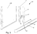
- the base body 8 can in particular be formed from sheet metal. The attachment of the locking system 1 to the base body 8 is shown in FIG Fig. 3 indicated.
- the control cabinet door 2 can in particular have only one locking system 1.
- the closure system 1 can in particular only have one stiffening profile 7.
- stiffening profile 7 extends over an essentially complete height of the control cabinet door 2.
- the stiffening profile 7 has a plurality of fastening devices for fastening to the base body 8.
- the fastening devices can in particular be screw bushings.
- the control cabinet door 2 can further preferably have an actuating device 18, via which actuating device 18 the at least one locking rod can be moved from the locking position into the release position.
- the actuating device 18 can in particular have a lock, a movable handle or a button.
- the actuating device 18 can furthermore have movable push rods 19 which can be fastened to the locking rods 3, in particular to a second end of the locking rods 3. The possibility of attaching the push rod 19 to the locking rod 3 is in the Fig. 4 indicated.
- the stiffening profile 7 can have a recess, in particular in the area of the actuating device 18, so that the stiffening profile 7 can be placed on an existing actuating device 18.
- a control cabinet 15 comprising at least one locking system 1 is also provided.
- the control cabinet 15 can in particular be a sheet metal cabinet.
- the control cabinet can in particular have a control cabinet housing 6.
- the control cabinet housing 6 can in particular comprise a frame and sheet metal claddings attached to the frame.
- the control cabinet 15 can in particular have one or two control cabinet doors 2, which are equipped with the locking system 1.
- the control cabinet 15 can in particular be designed like a conventional control cabinet 15, apart from the new locking system 1.
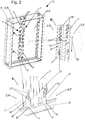
- a preferred embodiment of the control cabinet 15 is in the Fig. 1 and 2nd shown, wherein in Fig. 2 the sheet metal cladding is not shown.
- the control cabinet 15 has two control cabinet doors 2, the locking rods 3 of one of the two control cabinet doors 2 being in the release position and the locking rods 3 of the other control cabinet door 2 being in the locking position.
- locking receptacles 9 with associated locking extensions 10 are provided.
- locking projections 10 can be arranged in the region of the first end 4 and the second end of the locking rod 3. As a result, the applied force can be derived over a large area.
- the stiffening profile 7 has at least two parallel contact areas 11 for resting on the base body 8 of the control cabinet door 2, and that the two contact areas are connected to one another by a U-shaped web 12.
- the fastening devices of the stiffening profile 7 can be arranged in the contact areas 11.
- the locking receptacles 9 can be formed in the area of the web.
- the stiffening profile 7 has additional stiffening ribs which are formed on a side of the contact regions 11 facing away from the web 12.
- the stiffening profile 7 thereby has a substantially W-shaped profile.
- the stiffening profile 7 can be additionally stiffened.
- the at least one locking receptacle 9 is designed as a recess in the web 12.
- the recess in the web 12 can lead to a lack of the web 12 in some areas.
- the at least one locking receptacle 9 can be particularly simple.
- the at least one locking extension 10 is hook-shaped and engages behind the web 11 in the locking position.
- the at least one locking extension 10 can be made very simple, and in the event of an explosion in the control cabinet 15 it reliably holds the locking rod 3 on the stiffening profile 7.
- the at least one locking rod 3 has an essentially U-shaped profile with two legs 13 and a central part 14 connecting the legs 13 to one another.
- the at least one locking rod 3 is considerably stiffer than a locking rod 3 which is merely designed as a flat strip.
- the locking extensions 10 are arranged symmetrically on both legs 13.
- two locking projections 10 are assigned only one locking receptacle 9.
- the at least one locking extension 10 is designed in alignment with one of the legs 13.
- the at least one locking extension 10 can be designed as an extension of the leg 13.
- the locking rod 3 can be punched out of one piece together with the locking projections 10 and then bent, which makes them particularly simple but also robust
Landscapes
- Engineering & Computer Science (AREA)
- Mechanical Engineering (AREA)
- Cabinets, Racks, Or The Like Of Rigid Construction (AREA)
- Casings For Electric Apparatus (AREA)
- Patch Boards (AREA)
Description
- Die Erfindung betrifft ein Verschlusssystem für eine Schaltschranktür gemäß dem Oberbegriff des Patentanspruches 1.
- Es sind Schaltschränke bekannt, deren Türen mittels eines Verschlusssystems mit Verschlussstangen verschließbar sind. Hierbei greift ein Ende der Verschlussstange in einer Verriegelungsstellung in eine Öffnung des Schaltschrankgehäuses ein, um die Schaltschranktür in der geschlossenen Position zu halten. Die Verschlussstangen werden dabei durch eine Halterung im Bereich des freien Endes gehalten.
- Nachteilig an derartigen Verschlusssystemen ist, dass diese oft nicht ausreichend sind, um den Druck bei einer Explosion im Schaltschrank, beispielsweise durch einen Störlichtbogen, standzuhalten. Hierbei wird oftmals die Halterung der Verschlussstange ausgerissen oder die Schaltschranktür verwindet sich bei der Explosion so stark, dass die Verschlussstange aus der Öffnung des Schaltschrankgehäuses gezogen wird. Bei einem Versagen der Schaltschranktür besteht ein hohes Risiko, dass umstehende Personen oder Geräte geschädigt werden, beziehungsweise die Umgebung in Brand gesteckt wird.
- Die
US 2003/151337 A1 beschreibt einen Schaltschrank mit einer Mehrzahl an Sicherheitseinrichtungen, die an einem vertikalen Flansch des Schaltschrankes befestigt sind. Jede der Sicherheitseinrichtungen umfasst ein Loch und einen Pin um in dieses einzugreifen. - Aus der
DE 20 2011 004 196 U1 ist eine Verschlussvorrichtung für einen Geräteschrank bekannt, welche mehrere Riegel bzw. Zusatzriegel aufweist. - Die
DE 199 39 614 C1 und dieUS 2012/0194044 A1 offenbaren einen druckfesten Schaltschrank, mit einer entsprechend druckfest verriegelbaren Schaltschranktür. - Aufgabe der Erfindung ist es daher ein Verschlusssystem der eingangs genannten Art anzugeben, mit welchem die genannten Nachteile vermieden werden können, mit welchem eine Schaltschranktür derart ausgebildet werden kann, dass diese hohen Drücken standhalten kann, ohne dass der Aufwand zur Herstellung der Schaltschranktür erheblich vergrößert wird.
- Erfindungsgemäß wird dies durch die Merkmale des Patentanspruches 1 erreicht. Dadurch ergibt sich der Vorteil, dass eine mit dem Verschlusssystem ausgerüstete Schaltschranktür wesentlich höheren Drücken standhalten kann, wodurch die Umgebung besser vor den negativen Auswirkungen eines Störlichtbogens und der dadurch verursachten Explosion im Schaltschrank geschützt werden kann. Durch das Versteifungsprofil kann eine ansonsten herkömmlich ausgebildete Schaltschranktür wesentlich steifer ausgebildet werden, wodurch die Verschlussstangen auch bei höheren Drücken noch zuverlässig in die Öffnungen eingreifen können. Durch die in Verriegelungsaufnahmen und Verriegelungsfortsätze kann die Verschlusstange in der Verriegelungsstellung zusätzlich an mehreren Punkten befestigt sein, wodurch die Verschlussstange bei einer Explosion schwerer aus deren Halterung gerissen werden kann. Da diese zusätzliche Verankerung der Verschlusstange mit dem Versteifungsprofil lediglich in Verriegelungsstellung erfolgt und nicht in der Freigabestellung, kann eine Montage der Verschlusstange mit vergleichsweise wenig Aufwand erfolgen. Das Verschlusssystem kann weiters mit besonders wenigen Einzelteilen ausgebildet sein, was eine Montage zusätzlich erleichtert. Weiters können herkömmliche Schaltschränke einfach und mit wenig Aufwand mit dem neuen Verschlusssystem nachgerüstet werden. Zusätzlich ist das neue Verschlusssystem in der Bedienung nicht aufwendiger als herkömmliche Verschlusssysteme.
- Die Erfindung betrifft weiters eine Schaltschranktür gemäß dem Patentanspruch 8.
- Die Erfindung betrifft weiters einen Schaltschrank gemäß dem Patentanspruch 9.
- Die Unteransprüche betreffen weitere vorteilhafte Ausgestaltungen der Erfindung.
- Ausdrücklich wird hiermit auf den Wortlaut der Patentansprüche Bezug genommen, wodurch die Ansprüche an dieser Stelle durch Bezugnahme in die Beschreibung eingefügt sind und als wörtlich wiedergegeben gelten.
- Die Erfindung wird unter Bezugnahme auf die beigeschlossenen Zeichnungen, in welchen lediglich eine bevorzugte Ausführungsformen beispielhaft dargestellt ist, näher beschrieben. Dabei zeigt:
-
Fig. 1 eine bevorzugte Ausführungsform eines Schaltschrankes von schräg vorne als axonometrische Darstellung; -
Fig. 2 die bevorzugte Ausführungsform des Schaltschrankes von schräg hinten als axonometrische Darstellung, wobei Verkleidungsteile des Schaltschrankes nicht dargestellt sind, wobei zusätzlich die Bereiche A und B vergrößert dargestellt sind; -
Fig. 3 einen ersten Teil der bevorzugten Ausführungsform des Schaltschrankes als Explosionsdarstellung; -
Fig. 4 einen zweiten Teil der bevorzugte Ausführungsform des Schaltschrankes als Explosionsdarstellung; -
Fig. 5 einen dritten Teil der bevorzugten Ausführungsform des Schaltschrankes in der Freigabestellung als axonometrische Darstellung; -
Fig. 6 den dritten Teil ausFig. 5 in der Verrieglungsstellung, wobei Teile der Verschlussstange transparent dargestellt sind; -
Fig. 7 einen vierten Teil der bevorzugten Ausführungsform des Schaltschrankes in der Freigabestellung als axonometrische Darstellung; und -
Fig. 8 den vierten Teil ausFig. 7 in der Verrieglungsstellung, wobei Teile der Verschlussstange transparent dargestellt sind. - Die
Fig. 1 bis 8 zeigen zumindest Teile einer bevorzugten Ausführungsform eines Verschlusssystems 1 für eine Schaltschranktür 2, umfassend wenigstens eine zwischen einer Verriegelungsstellung und einer Freigabestellung vorgebbar bewegbare Verschlussstange 3, wobei ein erstes Ende 4 der Verschlussstange 3 vorgesehen ist, in der Verriegelungsstellung zum Verschließen der Schaltschranktür 2 in eine Öffnung 5 eines Schaltschrankgehäuses 6 einzugreifen. Das Verschlusssystem 1 ist ein System zum Verschließen einer Schaltschranktür 2. Hierfür weist das Verschlusssystem 1 eine Verschlussstange 3 auf, welche zwischen zwei Positionen bewegt werden kann. In der Verriegelungsposition der Verschlussstange 3 wird in einem eingebauten Zustand des Verschlusssystems 1 die Schaltschranktür 2 durch das in die Öffnung 5 des Schaltschrankgehäuses 6 eingreifende erste Ende 4 gehalten, während in der Freigabestellung die Schaltschranktür 2 geöffnet werden kann. In denFig. 5 und 7 ist das Verschlusssystems 1 der bevorzugten Ausführungsform in der Freigabestellung dargestellt, während inFig. 6 und 8 das Verschlusssystems 1 der bevorzugten Ausführungsform in der Verriegelungsstellung dargestellt ist. Die Bewegungsrichtung der Verschlussstange 3 ist inFig. 2 durch einen Doppelpfeil 16 angedeutet. In denFig. 1 bis 8 sind nicht alle Merkmale durchgehend mit Bezugszeichen versehen. - Vorgesehen ist, dass das Verschlusssystem 1 wenigstens ein im Wesentlichen parallel zu der Verschlussstange 3 verlaufendes Versteifungsprofil 7 aufweist, dass das Versteifungsprofil 7 zu einer lagefesten Befestigung an einen Grundkörper 8 der Schaltschranktür 2 vorgesehen ist, dass das wenigstens eine Versteifungsprofil 7 wenigstens eine Verriegelungsaufnahme 9 aufweist, und dass die Verschlussstange 3 wenigstens einen Verriegelungsfortsatz 10 aufweist, wobei der wenigstens eine Verriegelungsfortsatz 10 in der Verriegelungsstellung eine formschlüssige Verbindung mit der wenigstens einen Verriegelungsaufnahme 9 bildet und in der Freigabestellung die wenigstens eine Verriegelungsaufnahme 9 freigibt. Das Versteifungsprofil 7 ist dazu vorgesehen lagefest an der restlichen Schaltschranktür 2 befestigt zu werden.
- Das Versteifungsprofil 7, welches insbesondere als Blechprofil ausgebildet sein kann, weist eine parallel zur Verschlussstange 3 verlaufende Längserstreckung auf, und ist gegenüber der Verschlussstange 3 beweglich angeordnet. Durch die wenigstens eine Verriegelungsaufnahme 9 und den wenigstens einen Verriegelungsfortsatz 10 kann in der Verriegelungsstellung eine zusätzliche formschlüssige Verbindung zwischen Versteifungsprofil 7 und Verschlussstange 3 bereitgestellt werden, welche in der Freigabestellung wieder gelöst wird. Die formschlüssige Verbindung bezieht sich hierbei auf einen Formschluss bezüglich einer die Verschlussstange 3 von dem Versteifungsprofil 7 separierenden Kraft, wie diese bei einem Überdruck im Schaltschrank 15 entsteht. Dadurch kann eine Schaltschranktür 2 einfach zusätzlich versteift werden, wobei in der Verriegelungsstellung eine Druckkraft auf die Schaltschranktür 2 an mehreren Stellen von der Schaltschranktür 2 an die Verschlussstange 3 weitergeleitet werden kann.
- Dadurch ergibt sich der Vorteil, dass eine mit dem Verschlusssystem 1 ausgerüstete Schaltschranktür 2 wesentlich höheren Drücken standhalten kann, wodurch die Umgebung besser vor den negativen Auswirkungen eines Störlichtbogens und der dadurch verursachten Explosion im Schaltschrank 15 geschützt werden kann. Durch das Versteifungsprofil 7 kann eine ansonsten herkömmlich ausgebildete Schaltschranktür 2 wesentlich steifer ausgebildet werden, wodurch die Verschlussstangen 3 auch bei höheren Drücken noch zuverlässig in die Öffnungen 5 eingreifen können. Durch die in Verriegelungsaufnahmen 9 und Verriegelungsfortsätze 10 kann die Verschlusstange 3 in der Verriegelungsstellung zusätzlich an mehreren Punkten befestigt sein, wodurch die Verschlussstange 3 bei einer Explosion schwerer aus deren Halterung gerissen werden kann. Da diese zusätzliche Verankerung der Verschlusstange 3 mit dem Versteifungsprofil 7 lediglich in Verriegelungsstellung erfolgt und nicht in der Freigabestellung, kann eine Montage der Verschlusstange 3 mit vergleichsweise wenig Aufwand erfolgen. Das Verschlusssystem 1 kann weiters mit besonders wenigen Einzelteilen ausgebildet sein, was eine Montage zusätzlich erleichtert. Weiters können herkömmliche Schaltschränke 15 einfach und mit wenig Aufwand mit dem neuen Verschlusssystem 1 nachgerüstet werden. Zusätzlich ist das neue Verschlusssystem 1 in der Bedienung nicht aufwendiger als herkömmliche Verschlusssysteme 1.
- Weiters kann vorgesehen sein, dass die Verschlusstange 3 über wenigstens eine Halteeinrichtung 17 an dem Versteifungsprofil 7 beweglich befestigt ist. Die Halteeinrichtung 17 kann insbesondere Halteklammern umfassen, welche die Verschlussstange 3 auch in der Freigabestellung halten. In der Verriegelungsstellung kann die Verschlussstange 3 dabei von den Verriegelungsfortsätzen 10 als auch der Halteeinrichtung 17 an dem Versteifungsprofil 7 gehalten werden, wobei hier vorgesehen sein kann, dass die Verriegelungsfortsätzen 10 höhere Kräfte aufnehmen können als die Halteeinrichtung 17.
- Das Verschlusssystem 1 kann insbesondere zwei Verschlussstange 3 aufweisen, wobei eine Verschlussstange 3 in einem Bodenbereich angeordnet ist und eine weitere Verschlussstange 3 in einem Deckenbereich.
- Insbesondere kann eine Schaltschranktür 2 umfassend das Verschlusssystem 1 vorgesehen sein. Die Schaltschranktür 2 kann insbesondere einen Grundkörper 8 aufweisen, an welchem das Versteifungsprofil 7 lagefest befestigt ist. Die Schaltschranktür 2 kann weiters über wenigstens ein Scharnier verfügen, mit welchem der Grundkörper 8 an das Schaltschrankgehäuse 6 befestigbar ist. Der Grundkörper 8 kann insbesondere aus Blech ausgebildet sein. Die Anbringung des Verschlusssystems 1 an den Grundkörper 8 ist in
Fig. 3 angedeutet. - Die Schaltschranktür 2 kann insbesondere lediglich ein Verschlusssystem 1 aufweisen.
- Das Verschlusssystem 1 kann insbesondere lediglich ein Versteifungsprofil 7 aufweisen.
- Weiters kann vorgesehen sein, dass das Versteifungsprofil 7 über eine im Wesentlichen komplette Höhe der Schaltschranktür 2 verläuft.
- Bevorzugt kann vorgesehen sein, dass das Versteifungsprofil 7 mehrere Befestigungseinrichtungen zur Befestigung an den Grundkörper 8 aufweist. Die Befestigungseinrichtungen können insbesondere Schraubendurchführungen sein.
- Die Schaltschranktür 2 kann weiters bevorzugt eine Betätigungseinrichtung 18 aufweisen, über welche Betätigungseinrichtung 18 die wenigstens eine Verschlussstange von der Verriegelungsstellung in die Freigabestellung verbringbar ist. Die Betätigungseinrichtung 18 kann insbesondere ein Schloss, einen beweglichen Griff oder eine Taste aufweisen. Die Betätigungseinrichtung 18 kann weiters bewegliche Schubstangen 19 aufweisen, welche an den Verschlussstangen 3, insbesondere an einem zweiten Ende der Verschlussstangen 3, befestigbar sind. Die Möglichkeit der Befestigung der Schubstange 19 an die Verschlussstange 3 ist in der
Fig. 4 angedeutet. - Das Versteifungsprofil 7 kann insbesondere im Bereich der Betätigungseinrichtung 18 eine Aussparung aufweisen, sodass das Versteifungsprofil 7 auf eine bestehende Betätigungseinrichtung 18 aufgesetzt werden kann.
- Weiters ist ein Schaltschrank 15 umfassend wenigstens ein Verschlusssystem 1 vorgesehen. Der Schaltschrank 15 kann insbesondere ein Blechschrank sein. Der Schaltschrank kann insbesondere ein Schaltschrankgehäuse 6 aufweisen. Das Schaltschrankgehäuse 6 kann insbesondere einen Rahmen und am Rahmen angebrachte Blechverkleidungen umfassen. Der Schaltschrank15 kann insbesondere über eine oder zwei Schaltschranktüren 2 aufweisen, welche mit dem Verschlusssystem 1 ausgestattet sind. Der Schaltschrank 15 kann insbesondere abgesehen von den dem neuen Verschlusssystem 1 wie ein herkömmlicher Schaltschrank 15 ausgebildet sein.
- Eine bevorzugte Ausführungsform des Schaltschrankes 15 ist in den
Fig. 1 und2 dargestellt, wobei inFig. 2 die Blechverkleidung nicht dargestellt ist. InFig. 1 und2 weist der Schaltschrank 15 zwei Schaltschranktüren 2 auf, wobei die Verschlussstangen 3 einer der beiden Schaltschranktüren 2 in der Freigabestellung sind und die Verschlussstangen 3 der anderen Schaltschranktür 2 in der Verriegelungsstellung sind. - Besonders bevorzugt kann vorgesehen sein, dass mehrere Verriegelungsaufnahmen 9 mit zugeordneten Verriegelungsfortsätzen 10 vorgesehen sind. Insbesondere können Verriegelungsfortsätzen 10 im Bereich des ersten Endes 4 und des zweiten Endes der Verschlussstange 3 angeordnet sein. Dadurch kann die einwirkende Kraft auf einem großen Bereich abgeleitet werden.
- Besonders bevorzugt kann vorgesehen sein, dass das Versteifungsprofil 7 wenigstens zwei parallel verlaufende Kontaktbereiche 11 zur Auflage auf dem Grundkörper 8 der Schaltschranktür 2 aufweist, und dass die beiden Kontaktbereiche durch einen U-förmigen Steg 12 miteinander verbunden sind. In den Kontaktbereichen 11 können die Befestigungseinrichtungen des Versteifungsprofils 7 angeordnet sein. Die Verriegelungsaufnahmen 9 können im Bereich des Steges ausgebildet sein. Dadurch kann das Versteifungsprofil 7 besonders einfach ausgebildet werden.
- Weiters kann vorgesehen sein, dass das Versteifungsprofil 7 zusätzliche Versteifungsrippen aufweist, welche an einer dem Steg 12 abgewandten Seite der Kontaktbereiche 11 angeformt sind. Das Versteifungsprofil 7 hat dadurch ein im Wesentlichen W-förmiges Profil. Dadurch kann das Versteifungsprofil 7 zusätzlich versteift werden.
- Besonders bevorzugt kann vorgesehen sein, dass die wenigstens eine Verriegelungsaufnahme 9 als Aussparung des Steges 12 ausgebildet ist. Die Aussparung des Steges 12 kann bis zu einem bereichsweise Fehlen des Steges 12 führen. Dadurch kann die wenigstens eine Verriegelungsaufnahme 9 besonders einfach ausgebildet sein.
- Insbesondere kann vorgesehen sein, dass der wenigstens eine Verriegelungsfortsatz 10 hakenförmig ausgebildet ist und in der Verriegelungsstellung den Steg 11 hintergreift. Dadurch kann der wenigstens eine Verriegelungsfortsatz 10 sehr einfach ausgebildet sein, wobei dieser bei einer Explosion in dem Schaltschrank 15 zuverlässig die Verschlussstange 3 an dem Versteifungsprofil 7 hält.
- Besonders bevorzugt kann vorgesehen sein, dass die wenigstens eine Verschlussstange 3 ein im Wesentlichen U-förmiges Profil mit zwei Schenkeln 13 und einem, die Schenkeln 13 miteinander verbindenden Mittelteil 14 aufweist. Dadurch ist die wenigstens eine Verschlussstange 3 wesentlich steifer als eine lediglich als Flachband ausgebildete Verschlussstange 3.
- Insbesondere kann vorgesehen sein, dass die Verriegelungsfortsätze 10 symmetrisch auf beiden Schenkel 13 angeordnet sind.
- Weiters kann vorgesehen sein, dass zwei Verriegelungsfortsätzen 10 lediglich eine Verriegelungsaufnahme 9 zugeordnet ist.
- Insbesondere kann vorgesehen sein, dass der wenigstens eine Verriegelungsfortsatz 10 fluchtend zu einem der Schenkel 13 ausgebildet ist. Der wenigstens eine Verriegelungsfortsatz 10 kann hierbei als Verlängerung des Schenkels 13 ausgebildet werden. Dadurch kann die Verschlusstange 3 gemeinsam mit den Verriegelungsfortsätzen 10 aus einem Stück gestanzt, und anschließend gebogen werden, wodurch diese besonders einfach aber auch robust ausgebildet werden
Claims (9)
- Verschlusssystem (1) für eine Schaltschranktür (2), umfassend wenigstens eine zwischen einer Verriegelungsstellung und einer Freigabestellung vorgebbar bewegbare Verschlussstange (3), wobei ein erstes Ende (4) der Verschlussstange (3) vorgesehen ist, in der Verriegelungsstellung zum Verschließen der Schaltschranktür (2) in eine Öffnung (5) eines Schaltschrankgehäuses (6) einzugreifen, dadurch gekennzeichnet, dass das Verschlusssystem (1) wenigstens ein im Wesentlichen parallel zu der Verschlussstange (3) verlaufendes Versteifungsprofil (7) aufweist, dass das Versteifungsprofil (7) zu einer lagefesten Befestigung an einen Grundkörper (8) der Schaltschranktür (2) vorgesehen ist, dass das wenigstens eine Versteifungsprofil (7) wenigstens eine Verriegelungsaufnahme (9) aufweist, und dass die Verschlussstange (3) wenigstens einen Verriegelungsfortsatz (10) aufweist, wobei der wenigstens eine Verriegelungsfortsatz (10) in der Verriegelungsstellung eine formschlüssige Verbindung mit der wenigstens einen Verriegelungsaufnahme (9) bildet und in der Freigabestellung die wenigstens eine Verriegelungsaufnahme (9) freigibt.
- Verschlusssystem (1) nach Anspruch 1, dadurch gekennzeichnet, dass mehrere Verriegelungsaufnahmen (9) mit zugeordneten Verriegelungsfortsätzen (10) vorgesehen sind.
- Verschlusssystem (1) nach Anspruch 1 oder 2, dadurch gekennzeichnet, dass das Versteifungsprofil (7) wenigstens zwei parallel verlaufende Kontaktbereiche (11) zur Auflage auf dem Grundkörper (8) der Schaltschranktür (2) aufweist, und dass die beiden Kontaktbereiche durch einen U-förmigen Steg (12) miteinander verbunden sind.
- Verschlusssystem (1) nach Anspruch 3, dadurch gekennzeichnet, dass die wenigstens eine Verriegelungsaufnahme (9) als Aussparung des Steges (12) ausgebildet ist.
- Verschlusssystem (1) nach Anspruch 3 oder 4, dadurch gekennzeichnet, dass der wenigstens eine Verriegelungsfortsatz (10) hakenförmig ausgebildet ist und in der Verriegelungsstellung den Steg (11) hintergreift.
- Verschlusssystem (1) nach einem der Ansprüche 1 bis 4, dadurch gekennzeichnet, dass die wenigstens eine Verschlussstange (3) ein im Wesentlichen U-förmiges Profil mit zwei Schenkeln (13) und einem, die Schenkeln (13) miteinander verbindenden Mittelteil (14) aufweist.
- Verschlusssystem (1) nach Anspruch 6, dadurch gekennzeichnet, dass der wenigstens eine Verriegelungsfortsatz (10) fluchtend zu einem der Schenkel (13) ausgebildet ist.
- Schaltschranktür (2) umfassend ein Verschlusssystem (1) nach einem der Ansprüche 1 bis 7.
- Schaltschrank (15) umfassend wenigstens ein Verschlusssystem (1) nach einem der Ansprüche 1 bis 7.
Applications Claiming Priority (1)
| Application Number | Priority Date | Filing Date | Title |
|---|---|---|---|
| DE102017129863.0A DE102017129863A1 (de) | 2017-12-13 | 2017-12-13 | Verschlusssystem für Schaltschranktür |
Publications (2)
| Publication Number | Publication Date |
|---|---|
| EP3498954A1 EP3498954A1 (de) | 2019-06-19 |
| EP3498954B1 true EP3498954B1 (de) | 2020-07-29 |
Family
ID=64664589
Family Applications (1)
| Application Number | Title | Priority Date | Filing Date |
|---|---|---|---|
| EP18211170.8A Active EP3498954B1 (de) | 2017-12-13 | 2018-12-07 | Verschlusssystem für schaltschranktür |
Country Status (2)
| Country | Link |
|---|---|
| EP (1) | EP3498954B1 (de) |
| DE (1) | DE102017129863A1 (de) |
Family Cites Families (6)
| Publication number | Priority date | Publication date | Assignee | Title |
|---|---|---|---|---|
| DE19939614C1 (de) * | 1999-08-20 | 2001-09-27 | Driescher Eltech Werk | Druckfester Schaltschrank |
| US6746092B2 (en) * | 2002-02-13 | 2004-06-08 | Eaton Corporation | Apparatus for securing a door of an arc-resistant switchgear cabinet |
| WO2012103183A1 (en) * | 2011-01-26 | 2012-08-02 | Abb Technology Ag | Switchgear enclosure with improved door assembly |
| US8419141B2 (en) * | 2011-01-27 | 2013-04-16 | Eaton Corporation | Switchgear door latching system |
| DE202011004196U1 (de) * | 2011-03-21 | 2011-08-25 | Knürr AG | Verschlussvorrichtung |
| EP2843781B1 (de) * | 2013-08-28 | 2019-03-20 | ABB S.p.A. | Türverriegelungsmittel für einen elektrischen Schaltschrank |
-
2017
- 2017-12-13 DE DE102017129863.0A patent/DE102017129863A1/de not_active Withdrawn
-
2018
- 2018-12-07 EP EP18211170.8A patent/EP3498954B1/de active Active
Non-Patent Citations (1)
| Title |
|---|
| None * |
Also Published As
| Publication number | Publication date |
|---|---|
| EP3498954A1 (de) | 2019-06-19 |
| DE102017129863A1 (de) | 2019-06-13 |
Similar Documents
| Publication | Publication Date | Title |
|---|---|---|
| DE3815890C2 (de) | Fernbetätigter Riegelmechanismus | |
| DE10050959B4 (de) | Sitzlängsverstellung | |
| WO2018228877A1 (de) | Tragschienenbefestigung | |
| DE102010037106B4 (de) | Mechanische Sicherheitsvorrichtung für eine Spritzgussmaschine | |
| DE4312025C2 (de) | Druckfester Schaltschrank, insbesondere für Mittelspannungs-Schaltanlagen | |
| DE19939614C1 (de) | Druckfester Schaltschrank | |
| EP2407604B1 (de) | Verbindungsvorrichtung | |
| DE202016101097U1 (de) | Verriegelungseinrichtung und dazugehörige Schiebetüranlage | |
| WO2011091822A1 (de) | Installationsschaltgerät mit verrastbaren gehäusehälften | |
| EP3498954A1 (de) | Verschlusssystem für schaltschranktür | |
| EP3045644A1 (de) | Vorrichtung zum verhindern des schliessens einer tür | |
| EP0616403A1 (de) | Wandinstallationskanal | |
| EP0619635B1 (de) | Sammelhalter für Kabel oder Rohre | |
| DE7532352U (de) | Schalt zelle | |
| AT409432B (de) | Einrichtung zum plombieren und verriegeln des deckels eines sicherungsschaltgerätes | |
| AT520789B1 (de) | Anordnung aus Ausziehführung und Mitnehmer | |
| EP1026801B1 (de) | Trennkontaktblock für Einschub-Leistungsschalter | |
| DE2812142C2 (de) | Auflageelement zur Befestigung von Rahmen in Schränken zur Aufnahme elektromechanischer Geräte | |
| DE29908320U1 (de) | Höhenverstellvorrichtung für Gurtbeschlag | |
| DE102010036081A1 (de) | Abgangskasten | |
| CH697252B1 (de) | Verriegelungssystem für ein modulares Schranksystem. | |
| DE1158145B (de) | Anordnung zum Befestigen von elektrischen Geraeten an Hohlschienen | |
| DE2532549C3 (de) | Befestigung eines Gehäuses, insbesondere für elektrische und elektronische Geräte | |
| AT512447B1 (de) | Schaltschrank mit Vertikalsteg | |
| AT206043B (de) | Mehrfach-Kommandoschalter |
Legal Events
| Date | Code | Title | Description |
|---|---|---|---|
| PUAI | Public reference made under article 153(3) epc to a published international application that has entered the european phase |
Free format text: ORIGINAL CODE: 0009012 |
|
| STAA | Information on the status of an ep patent application or granted ep patent |
Free format text: STATUS: THE APPLICATION HAS BEEN PUBLISHED |
|
| AK | Designated contracting states |
Kind code of ref document: A1 Designated state(s): AL AT BE BG CH CY CZ DE DK EE ES FI FR GB GR HR HU IE IS IT LI LT LU LV MC MK MT NL NO PL PT RO RS SE SI SK SM TR |
|
| AX | Request for extension of the european patent |
Extension state: BA ME |
|
| STAA | Information on the status of an ep patent application or granted ep patent |
Free format text: STATUS: REQUEST FOR EXAMINATION WAS MADE |
|
| 17P | Request for examination filed |
Effective date: 20191210 |
|
| RBV | Designated contracting states (corrected) |
Designated state(s): AL AT BE BG CH CY CZ DE DK EE ES FI FR GB GR HR HU IE IS IT LI LT LU LV MC MK MT NL NO PL PT RO RS SE SI SK SM TR |
|
| GRAP | Despatch of communication of intention to grant a patent |
Free format text: ORIGINAL CODE: EPIDOSNIGR1 |
|
| STAA | Information on the status of an ep patent application or granted ep patent |
Free format text: STATUS: GRANT OF PATENT IS INTENDED |
|
| RIC1 | Information provided on ipc code assigned before grant |
Ipc: H02B 1/38 20060101ALI20200124BHEP Ipc: E05C 9/04 20060101AFI20200124BHEP |
|
| INTG | Intention to grant announced |
Effective date: 20200227 |
|
| GRAS | Grant fee paid |
Free format text: ORIGINAL CODE: EPIDOSNIGR3 |
|
| GRAA | (expected) grant |
Free format text: ORIGINAL CODE: 0009210 |
|
| STAA | Information on the status of an ep patent application or granted ep patent |
Free format text: STATUS: THE PATENT HAS BEEN GRANTED |
|
| AK | Designated contracting states |
Kind code of ref document: B1 Designated state(s): AL AT BE BG CH CY CZ DE DK EE ES FI FR GB GR HR HU IE IS IT LI LT LU LV MC MK MT NL NO PL PT RO RS SE SI SK SM TR |
|
| REG | Reference to a national code |
Ref country code: CH Ref legal event code: EP |
|
| REG | Reference to a national code |
Ref country code: AT Ref legal event code: REF Ref document number: 1295987 Country of ref document: AT Kind code of ref document: T Effective date: 20200815 |
|
| REG | Reference to a national code |
Ref country code: IE Ref legal event code: FG4D Free format text: LANGUAGE OF EP DOCUMENT: GERMAN |
|
| REG | Reference to a national code |
Ref country code: DE Ref legal event code: R096 Ref document number: 502018002021 Country of ref document: DE |
|
| REG | Reference to a national code |
Ref country code: NL Ref legal event code: FP |
|
| REG | Reference to a national code |
Ref country code: SE Ref legal event code: TRGR |
|
| REG | Reference to a national code |
Ref country code: LT Ref legal event code: MG4D |
|
| PG25 | Lapsed in a contracting state [announced via postgrant information from national office to epo] |
Ref country code: GR Free format text: LAPSE BECAUSE OF FAILURE TO SUBMIT A TRANSLATION OF THE DESCRIPTION OR TO PAY THE FEE WITHIN THE PRESCRIBED TIME-LIMIT Effective date: 20201030 Ref country code: ES Free format text: LAPSE BECAUSE OF FAILURE TO SUBMIT A TRANSLATION OF THE DESCRIPTION OR TO PAY THE FEE WITHIN THE PRESCRIBED TIME-LIMIT Effective date: 20200729 Ref country code: PT Free format text: LAPSE BECAUSE OF FAILURE TO SUBMIT A TRANSLATION OF THE DESCRIPTION OR TO PAY THE FEE WITHIN THE PRESCRIBED TIME-LIMIT Effective date: 20201130 Ref country code: NO Free format text: LAPSE BECAUSE OF FAILURE TO SUBMIT A TRANSLATION OF THE DESCRIPTION OR TO PAY THE FEE WITHIN THE PRESCRIBED TIME-LIMIT Effective date: 20201029 Ref country code: FI Free format text: LAPSE BECAUSE OF FAILURE TO SUBMIT A TRANSLATION OF THE DESCRIPTION OR TO PAY THE FEE WITHIN THE PRESCRIBED TIME-LIMIT Effective date: 20200729 Ref country code: BG Free format text: LAPSE BECAUSE OF FAILURE TO SUBMIT A TRANSLATION OF THE DESCRIPTION OR TO PAY THE FEE WITHIN THE PRESCRIBED TIME-LIMIT Effective date: 20201029 Ref country code: LT Free format text: LAPSE BECAUSE OF FAILURE TO SUBMIT A TRANSLATION OF THE DESCRIPTION OR TO PAY THE FEE WITHIN THE PRESCRIBED TIME-LIMIT Effective date: 20200729 Ref country code: HR Free format text: LAPSE BECAUSE OF FAILURE TO SUBMIT A TRANSLATION OF THE DESCRIPTION OR TO PAY THE FEE WITHIN THE PRESCRIBED TIME-LIMIT Effective date: 20200729 |
|
| PG25 | Lapsed in a contracting state [announced via postgrant information from national office to epo] |
Ref country code: IS Free format text: LAPSE BECAUSE OF FAILURE TO SUBMIT A TRANSLATION OF THE DESCRIPTION OR TO PAY THE FEE WITHIN THE PRESCRIBED TIME-LIMIT Effective date: 20201129 Ref country code: LV Free format text: LAPSE BECAUSE OF FAILURE TO SUBMIT A TRANSLATION OF THE DESCRIPTION OR TO PAY THE FEE WITHIN THE PRESCRIBED TIME-LIMIT Effective date: 20200729 Ref country code: RS Free format text: LAPSE BECAUSE OF FAILURE TO SUBMIT A TRANSLATION OF THE DESCRIPTION OR TO PAY THE FEE WITHIN THE PRESCRIBED TIME-LIMIT Effective date: 20200729 |
|
| PG25 | Lapsed in a contracting state [announced via postgrant information from national office to epo] |
Ref country code: CZ Free format text: LAPSE BECAUSE OF FAILURE TO SUBMIT A TRANSLATION OF THE DESCRIPTION OR TO PAY THE FEE WITHIN THE PRESCRIBED TIME-LIMIT Effective date: 20200729 Ref country code: DK Free format text: LAPSE BECAUSE OF FAILURE TO SUBMIT A TRANSLATION OF THE DESCRIPTION OR TO PAY THE FEE WITHIN THE PRESCRIBED TIME-LIMIT Effective date: 20200729 Ref country code: RO Free format text: LAPSE BECAUSE OF FAILURE TO SUBMIT A TRANSLATION OF THE DESCRIPTION OR TO PAY THE FEE WITHIN THE PRESCRIBED TIME-LIMIT Effective date: 20200729 Ref country code: EE Free format text: LAPSE BECAUSE OF FAILURE TO SUBMIT A TRANSLATION OF THE DESCRIPTION OR TO PAY THE FEE WITHIN THE PRESCRIBED TIME-LIMIT Effective date: 20200729 Ref country code: IT Free format text: LAPSE BECAUSE OF FAILURE TO SUBMIT A TRANSLATION OF THE DESCRIPTION OR TO PAY THE FEE WITHIN THE PRESCRIBED TIME-LIMIT Effective date: 20200729 Ref country code: SM Free format text: LAPSE BECAUSE OF FAILURE TO SUBMIT A TRANSLATION OF THE DESCRIPTION OR TO PAY THE FEE WITHIN THE PRESCRIBED TIME-LIMIT Effective date: 20200729 |
|
| REG | Reference to a national code |
Ref country code: DE Ref legal event code: R097 Ref document number: 502018002021 Country of ref document: DE |
|
| PG25 | Lapsed in a contracting state [announced via postgrant information from national office to epo] |
Ref country code: AL Free format text: LAPSE BECAUSE OF FAILURE TO SUBMIT A TRANSLATION OF THE DESCRIPTION OR TO PAY THE FEE WITHIN THE PRESCRIBED TIME-LIMIT Effective date: 20200729 |
|
| PLBE | No opposition filed within time limit |
Free format text: ORIGINAL CODE: 0009261 |
|
| STAA | Information on the status of an ep patent application or granted ep patent |
Free format text: STATUS: NO OPPOSITION FILED WITHIN TIME LIMIT |
|
| PG25 | Lapsed in a contracting state [announced via postgrant information from national office to epo] |
Ref country code: SK Free format text: LAPSE BECAUSE OF FAILURE TO SUBMIT A TRANSLATION OF THE DESCRIPTION OR TO PAY THE FEE WITHIN THE PRESCRIBED TIME-LIMIT Effective date: 20200729 |
|
| 26N | No opposition filed |
Effective date: 20210430 |
|
| PG25 | Lapsed in a contracting state [announced via postgrant information from national office to epo] |
Ref country code: SI Free format text: LAPSE BECAUSE OF FAILURE TO SUBMIT A TRANSLATION OF THE DESCRIPTION OR TO PAY THE FEE WITHIN THE PRESCRIBED TIME-LIMIT Effective date: 20200729 Ref country code: MC Free format text: LAPSE BECAUSE OF FAILURE TO SUBMIT A TRANSLATION OF THE DESCRIPTION OR TO PAY THE FEE WITHIN THE PRESCRIBED TIME-LIMIT Effective date: 20200729 |
|
| REG | Reference to a national code |
Ref country code: BE Ref legal event code: MM Effective date: 20201231 |
|
| PG25 | Lapsed in a contracting state [announced via postgrant information from national office to epo] |
Ref country code: LU Free format text: LAPSE BECAUSE OF NON-PAYMENT OF DUE FEES Effective date: 20201207 Ref country code: FR Free format text: LAPSE BECAUSE OF NON-PAYMENT OF DUE FEES Effective date: 20201231 Ref country code: IE Free format text: LAPSE BECAUSE OF NON-PAYMENT OF DUE FEES Effective date: 20201207 |
|
| PG25 | Lapsed in a contracting state [announced via postgrant information from national office to epo] |
Ref country code: TR Free format text: LAPSE BECAUSE OF FAILURE TO SUBMIT A TRANSLATION OF THE DESCRIPTION OR TO PAY THE FEE WITHIN THE PRESCRIBED TIME-LIMIT Effective date: 20200729 Ref country code: MT Free format text: LAPSE BECAUSE OF FAILURE TO SUBMIT A TRANSLATION OF THE DESCRIPTION OR TO PAY THE FEE WITHIN THE PRESCRIBED TIME-LIMIT Effective date: 20200729 Ref country code: CY Free format text: LAPSE BECAUSE OF FAILURE TO SUBMIT A TRANSLATION OF THE DESCRIPTION OR TO PAY THE FEE WITHIN THE PRESCRIBED TIME-LIMIT Effective date: 20200729 |
|
| PG25 | Lapsed in a contracting state [announced via postgrant information from national office to epo] |
Ref country code: MK Free format text: LAPSE BECAUSE OF FAILURE TO SUBMIT A TRANSLATION OF THE DESCRIPTION OR TO PAY THE FEE WITHIN THE PRESCRIBED TIME-LIMIT Effective date: 20200729 |
|
| PG25 | Lapsed in a contracting state [announced via postgrant information from national office to epo] |
Ref country code: BE Free format text: LAPSE BECAUSE OF NON-PAYMENT OF DUE FEES Effective date: 20201231 |
|
| REG | Reference to a national code |
Ref country code: CH Ref legal event code: PL |
|
| PG25 | Lapsed in a contracting state [announced via postgrant information from national office to epo] |
Ref country code: LI Free format text: LAPSE BECAUSE OF NON-PAYMENT OF DUE FEES Effective date: 20211231 Ref country code: CH Free format text: LAPSE BECAUSE OF NON-PAYMENT OF DUE FEES Effective date: 20211231 |
|
| P01 | Opt-out of the competence of the unified patent court (upc) registered |
Effective date: 20230521 |
|
| REG | Reference to a national code |
Ref country code: AT Ref legal event code: MM01 Ref document number: 1295987 Country of ref document: AT Kind code of ref document: T Effective date: 20231207 |
|
| PG25 | Lapsed in a contracting state [announced via postgrant information from national office to epo] |
Ref country code: AT Free format text: LAPSE BECAUSE OF NON-PAYMENT OF DUE FEES Effective date: 20231207 |
|
| PGFP | Annual fee paid to national office [announced via postgrant information from national office to epo] |
Ref country code: NL Payment date: 20251119 Year of fee payment: 8 |
|
| PGFP | Annual fee paid to national office [announced via postgrant information from national office to epo] |
Ref country code: DE Payment date: 20251126 Year of fee payment: 8 |
|
| PGFP | Annual fee paid to national office [announced via postgrant information from national office to epo] |
Ref country code: GB Payment date: 20251120 Year of fee payment: 8 |
|
| PGFP | Annual fee paid to national office [announced via postgrant information from national office to epo] |
Ref country code: SE Payment date: 20251119 Year of fee payment: 8 |
|
| PGFP | Annual fee paid to national office [announced via postgrant information from national office to epo] |
Ref country code: PL Payment date: 20251124 Year of fee payment: 8 |
|
| PGFP | Annual fee paid to national office [announced via postgrant information from national office to epo] |
Ref country code: AT Payment date: 20260410 Year of fee payment: 5 |