EP3499003B1 - Système d'alimentation en air pour un moteur à combustion interne - Google Patents
Système d'alimentation en air pour un moteur à combustion interne Download PDFInfo
- Publication number
- EP3499003B1 EP3499003B1 EP17207260.5A EP17207260A EP3499003B1 EP 3499003 B1 EP3499003 B1 EP 3499003B1 EP 17207260 A EP17207260 A EP 17207260A EP 3499003 B1 EP3499003 B1 EP 3499003B1
- Authority
- EP
- European Patent Office
- Prior art keywords
- air
- engine
- coolant
- compressor
- evaporator
- Prior art date
- Legal status (The legal status is an assumption and is not a legal conclusion. Google has not performed a legal analysis and makes no representation as to the accuracy of the status listed.)
- Active
Links
Images

Classifications
-
- F—MECHANICAL ENGINEERING; LIGHTING; HEATING; WEAPONS; BLASTING
- F02—COMBUSTION ENGINES; HOT-GAS OR COMBUSTION-PRODUCT ENGINE PLANTS
- F02M—SUPPLYING COMBUSTION ENGINES IN GENERAL WITH COMBUSTIBLE MIXTURES OR CONSTITUENTS THEREOF
- F02M31/00—Apparatus for thermally treating combustion-air, fuel, or fuel-air mixture
- F02M31/20—Apparatus for thermally treating combustion-air, fuel, or fuel-air mixture for cooling
- F02M31/205—Control
-
- B—PERFORMING OPERATIONS; TRANSPORTING
- B60—VEHICLES IN GENERAL
- B60H—ARRANGEMENTS OF HEATING, COOLING, VENTILATING OR OTHER AIR-TREATING DEVICES SPECIALLY ADAPTED FOR PASSENGER OR GOODS SPACES OF VEHICLES
- B60H1/00—Heating, cooling or ventilating devices
- B60H1/00271—HVAC devices specially adapted for particular vehicle parts or components and being connected to the vehicle HVAC unit
-
- B—PERFORMING OPERATIONS; TRANSPORTING
- B60—VEHICLES IN GENERAL
- B60H—ARRANGEMENTS OF HEATING, COOLING, VENTILATING OR OTHER AIR-TREATING DEVICES SPECIALLY ADAPTED FOR PASSENGER OR GOODS SPACES OF VEHICLES
- B60H1/00—Heating, cooling or ventilating devices
- B60H1/00321—Heat exchangers for air-conditioning devices
- B60H1/00328—Heat exchangers for air-conditioning devices of the liquid-air type
-
- B—PERFORMING OPERATIONS; TRANSPORTING
- B60—VEHICLES IN GENERAL
- B60H—ARRANGEMENTS OF HEATING, COOLING, VENTILATING OR OTHER AIR-TREATING DEVICES SPECIALLY ADAPTED FOR PASSENGER OR GOODS SPACES OF VEHICLES
- B60H1/00—Heating, cooling or ventilating devices
- B60H1/00642—Control systems or circuits; Control members or indication devices for heating, cooling or ventilating devices
- B60H1/00735—Control systems or circuits characterised by their input, i.e. by the detection, measurement or calculation of particular conditions, e.g. signal treatment, dynamic models
- B60H1/00764—Control systems or circuits characterised by their input, i.e. by the detection, measurement or calculation of particular conditions, e.g. signal treatment, dynamic models the input being a vehicle driving condition, e.g. speed
-
- B—PERFORMING OPERATIONS; TRANSPORTING
- B60—VEHICLES IN GENERAL
- B60H—ARRANGEMENTS OF HEATING, COOLING, VENTILATING OR OTHER AIR-TREATING DEVICES SPECIALLY ADAPTED FOR PASSENGER OR GOODS SPACES OF VEHICLES
- B60H1/00—Heating, cooling or ventilating devices
- B60H1/32—Cooling devices
- B60H1/3202—Cooling devices using evaporation, i.e. not including a compressor, e.g. involving fuel or water evaporation
-
- B—PERFORMING OPERATIONS; TRANSPORTING
- B60—VEHICLES IN GENERAL
- B60H—ARRANGEMENTS OF HEATING, COOLING, VENTILATING OR OTHER AIR-TREATING DEVICES SPECIALLY ADAPTED FOR PASSENGER OR GOODS SPACES OF VEHICLES
- B60H1/00—Heating, cooling or ventilating devices
- B60H1/32—Cooling devices
- B60H1/3204—Cooling devices using compression
- B60H1/3227—Cooling devices using compression characterised by the arrangement or the type of heat exchanger, e.g. condenser, evaporator
-
- B—PERFORMING OPERATIONS; TRANSPORTING
- B60—VEHICLES IN GENERAL
- B60H—ARRANGEMENTS OF HEATING, COOLING, VENTILATING OR OTHER AIR-TREATING DEVICES SPECIALLY ADAPTED FOR PASSENGER OR GOODS SPACES OF VEHICLES
- B60H1/00—Heating, cooling or ventilating devices
- B60H1/32—Cooling devices
- B60H1/3204—Cooling devices using compression
- B60H1/323—Cooling devices using compression characterised by comprising auxiliary or multiple systems, e.g. plurality of evaporators, or by involving auxiliary cooling devices
-
- F—MECHANICAL ENGINEERING; LIGHTING; HEATING; WEAPONS; BLASTING
- F01—MACHINES OR ENGINES IN GENERAL; ENGINE PLANTS IN GENERAL; STEAM ENGINES
- F01P—COOLING OF MACHINES OR ENGINES IN GENERAL; COOLING OF INTERNAL-COMBUSTION ENGINES
- F01P3/00—Liquid cooling
- F01P3/12—Arrangements for cooling other engine or machine parts
-
- F—MECHANICAL ENGINEERING; LIGHTING; HEATING; WEAPONS; BLASTING
- F02—COMBUSTION ENGINES; HOT-GAS OR COMBUSTION-PRODUCT ENGINE PLANTS
- F02B—INTERNAL-COMBUSTION PISTON ENGINES; COMBUSTION ENGINES IN GENERAL
- F02B29/00—Engines characterised by provision for charging or scavenging not provided for in groups F02B25/00, F02B27/00 or F02B33/00 - F02B39/00; Details thereof
- F02B29/04—Cooling of air intake supply
- F02B29/0406—Layout of the intake air cooling or coolant circuit
- F02B29/0412—Multiple heat exchangers arranged in parallel or in series
-
- F—MECHANICAL ENGINEERING; LIGHTING; HEATING; WEAPONS; BLASTING
- F02—COMBUSTION ENGINES; HOT-GAS OR COMBUSTION-PRODUCT ENGINE PLANTS
- F02B—INTERNAL-COMBUSTION PISTON ENGINES; COMBUSTION ENGINES IN GENERAL
- F02B29/00—Engines characterised by provision for charging or scavenging not provided for in groups F02B25/00, F02B27/00 or F02B33/00 - F02B39/00; Details thereof
- F02B29/04—Cooling of air intake supply
- F02B29/0406—Layout of the intake air cooling or coolant circuit
- F02B29/0437—Liquid cooled heat exchangers
- F02B29/0443—Layout of the coolant or refrigerant circuit
-
- F—MECHANICAL ENGINEERING; LIGHTING; HEATING; WEAPONS; BLASTING
- F02—COMBUSTION ENGINES; HOT-GAS OR COMBUSTION-PRODUCT ENGINE PLANTS
- F02B—INTERNAL-COMBUSTION PISTON ENGINES; COMBUSTION ENGINES IN GENERAL
- F02B37/00—Engines characterised by provision of pumps driven at least for part of the time by exhaust
-
- B—PERFORMING OPERATIONS; TRANSPORTING
- B60—VEHICLES IN GENERAL
- B60H—ARRANGEMENTS OF HEATING, COOLING, VENTILATING OR OTHER AIR-TREATING DEVICES SPECIALLY ADAPTED FOR PASSENGER OR GOODS SPACES OF VEHICLES
- B60H1/00—Heating, cooling or ventilating devices
- B60H1/00271—HVAC devices specially adapted for particular vehicle parts or components and being connected to the vehicle HVAC unit
- B60H2001/003—Component temperature regulation using an air flow
-
- B—PERFORMING OPERATIONS; TRANSPORTING
- B60—VEHICLES IN GENERAL
- B60H—ARRANGEMENTS OF HEATING, COOLING, VENTILATING OR OTHER AIR-TREATING DEVICES SPECIALLY ADAPTED FOR PASSENGER OR GOODS SPACES OF VEHICLES
- B60H1/00—Heating, cooling or ventilating devices
- B60H1/32—Cooling devices
- B60H2001/3269—Cooling devices output of a control signal
- B60H2001/327—Cooling devices output of a control signal related to a compressing unit
-
- F—MECHANICAL ENGINEERING; LIGHTING; HEATING; WEAPONS; BLASTING
- F01—MACHINES OR ENGINES IN GENERAL; ENGINE PLANTS IN GENERAL; STEAM ENGINES
- F01P—COOLING OF MACHINES OR ENGINES IN GENERAL; COOLING OF INTERNAL-COMBUSTION ENGINES
- F01P2060/00—Cooling circuits using auxiliaries
- F01P2060/02—Intercooler
-
- F—MECHANICAL ENGINEERING; LIGHTING; HEATING; WEAPONS; BLASTING
- F01—MACHINES OR ENGINES IN GENERAL; ENGINE PLANTS IN GENERAL; STEAM ENGINES
- F01P—COOLING OF MACHINES OR ENGINES IN GENERAL; COOLING OF INTERNAL-COMBUSTION ENGINES
- F01P9/00—Cooling having pertinent characteristics not provided for in, or of interest apart from, groups F01P1/00 - F01P7/00
- F01P9/06—Cooling having pertinent characteristics not provided for in, or of interest apart from, groups F01P1/00 - F01P7/00 by use of refrigerating apparatus, e.g. of compressor or absorber type
-
- F—MECHANICAL ENGINEERING; LIGHTING; HEATING; WEAPONS; BLASTING
- F28—HEAT EXCHANGE IN GENERAL
- F28D—HEAT-EXCHANGE APPARATUS, NOT PROVIDED FOR IN ANOTHER SUBCLASS, IN WHICH THE HEAT-EXCHANGE MEDIA DO NOT COME INTO DIRECT CONTACT
- F28D21/00—Heat-exchange apparatus not covered by any of the groups F28D1/00 - F28D20/00
- F28D2021/0019—Other heat exchangers for particular applications; Heat exchange systems not otherwise provided for
- F28D2021/008—Other heat exchangers for particular applications; Heat exchange systems not otherwise provided for for vehicles
- F28D2021/0085—Evaporators
-
- Y—GENERAL TAGGING OF NEW TECHNOLOGICAL DEVELOPMENTS; GENERAL TAGGING OF CROSS-SECTIONAL TECHNOLOGIES SPANNING OVER SEVERAL SECTIONS OF THE IPC; TECHNICAL SUBJECTS COVERED BY FORMER USPC CROSS-REFERENCE ART COLLECTIONS [XRACs] AND DIGESTS
- Y02—TECHNOLOGIES OR APPLICATIONS FOR MITIGATION OR ADAPTATION AGAINST CLIMATE CHANGE
- Y02T—CLIMATE CHANGE MITIGATION TECHNOLOGIES RELATED TO TRANSPORTATION
- Y02T10/00—Road transport of goods or passengers
- Y02T10/10—Internal combustion engine [ICE] based vehicles
- Y02T10/12—Improving ICE efficiencies
Definitions
- the present invention relates to systems for feeding air to an internal combustion engine of a motor-vehicle, of the type comprising:
- the object of the invention is that of further improving the above-mentioned known systems, in particular with reference to an improved control of the system, an increase in its efficiency and, in particular, also with reference to a reduction in the fuel consumption of the engine.
- the invention relates to a system for feeding air to an internal combustion engine of a motor-vehicle having the features of claim 1.
- said first expansion valve and said second expansion valve are electronically-controlled expansion valves
- said electronic controller is configured to control both activation of said coolant compressor, and said first and second expansion valves according to signals indicating both the request for cooling the air fed to the engine, and the request for air conditioning of the passenger compartment of the motor-vehicle.
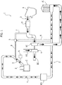
- numeral 1 indicates - in its entirety - a system for feeding air to an internal combustion engine of a motor-vehicle.
- the internal combustion engine is represented in the diagram of Figure 1 by one of its cylinders, which is indicated by C.
- the cylinder C is associated with at least one intake valve 2, which controls the supply of air into the cylinder C through an air feed duct 3.
- the duct 3 is provided with an air filter F, through which the ambient air is drawn into the duct 3.
- a debimeter D and a supercharging compressor SC are arranged in succession, the compressor including a rotor that is driven into rotation by a turbine T, which is actuated, according to a conventional art, by a flow of exhaust gases EG, which runs along the exhaust duct EC.
- a heat exchanger, or intercooler, IC is interposed, downstream of the air compressor SC, which, according to a conventional art, uses the coolant circulating in the cooling circuit of the engine (not illustrated) to cool the air flow fed by the air compressor SC.
- an evaporator E2 is arranged, downstream of the intercooler IC, in which coolant circulates in an air conditioning circuit of which the motor-vehicle is equipped.
- the reference number 4 indicates a throttle valve, interposed in the feed duct 3 downstream of the evaporator E2.
- the reference number 5 indicates a valve interposed in a duct for recirculating the feed air.
- This recirculation duct includes a portion 6 that originates from the duct 3, at a point downstream of the intercooler IC and upstream of the evaporator E2, and that terminates in the valve 5, and a second portion 7 that starts from the valve 5 and terminates in the duct 3, upstream of the compressor SC.
- the valve 5 receives, via a duct 8, a pressure signal of the feed air immediately upstream of the cylinder C, and opens to balance the pressure values upstream and downstream of the compressor SC, and is used to control and/or limit the maximum pressure exerted by the turbocompressor during the release steps of the accelerator, or rather, when the air introduced into the intake manifolds is greater than the amount required by the engine itself.
- the reference number 3 schematically indicates the air feed duct, in which the air filter F, the debimeter D, the air compressor SC, the intercooler IC and the evaporator E2 are interposed in series.
- Figure 2 also schematically shows the duct for exhaust gases EC, which originates from the engine exhaust manifold (indicated by the reference "ENG").
- the exhaust duct EC downstream of the engine ENG, the devices for treating the exhaust gases are placed, indicated as a whole by the reference EGT, which can vary according to the type of vehicle and the type of engine (for example, gasoline engine or diesel engine).
- the reference A/C indicates - in its entirety - the air conditioning system of which the motor-vehicle is equipped.
- the A/C system comprises a compressor CO for the coolant and a condenser CND that receives the coolant from the compressor CO.
- the reference TXV1 indicates a first expansion valve, for example, a thermostatic valve or an electronically-controlled valve, which receives condensed fluid from the condenser CND.
- the expanded fluid leaving the first expansion valve TXV1 passes through a main evaporator E1 for refrigerating an airflow directed towards the passenger compartment of the motor-vehicle.
- the fluid leaving the evaporator E1 returns through the first expansion valve TXV1 towards the compressor CO.
- the A/C air cooling system also comprises an inner heat exchanger IHX in which the flow of coolant that goes from the condenser CND to the first expansion valve TXV1 enters into a heat exchange relationship with the flow of fluid returning from the main evaporator E1 towards the compressor CO.
- the A/C system comprises a second evaporator E2, which is interposed in the duct for feeding air to the engine and which is connected to the coolant circuit in parallel with the main evaporator E1.
- a second expansion valve TXV2 is interposed in the connection between the condenser CND and the auxiliary evaporator E2.
- the inner heat exchanger IHX is connected in such a way that the fluid coming from the condenser CND passes through the inner heat exchanger IHX and then divides at the point P into two lines directed towards the two expansion valves TXV1 and TXV2, and towards the two evaporators E1, E2.
- Activation of the coolant compressor CO is controlled by an electronic controller ECU based on a series of signals S1, S2, ..., Si.
- activation can be controlled, for example, in that the compressor CO has a rotating shaft, which is connected in rotation with the shaft of the internal combustion engine ENG, with the interposition of an electrically-operated friction clutch (not shown).
- the controller ECU inserts and disengages this friction clutch to cause activation and deactivation of the coolant compressor CO.
- the controller ECU controls the activation of the coolant compressor CO, both as a function of the request for air conditioning of the passenger compartment of the motor-vehicle, and as a function of the request for cooling the air for feeding the engine
- the signals sent to the controller ECU include a signal indicating a manual operation of the air conditioning system A/C by the driver, a signal indicating the air temperature required by the driver, and a signal indicating the current air temperature in the passenger compartment of the motor-vehicle.
- the system comprises a sensor S of the air feed temperature ( Figure 1 ), which sends a signal indicating this value to the controller ECU.
- the electronic controller ECU receives signals indicating the operating conditions of the engine and, in particular, a signal indicating the load of the engine, corresponding to the position of the accelerator pedal, and a signal indicating the rotational speed of the engine.
- the electronic controller ECU takes into account, at all times, the request for cooling the air fed to the engine and the request for cooling the passenger compartment of the motor-vehicle, always favoring the thermal load which has the highest cooling requirement among the passenger compartment and the intake air.
- the electronic controller ECU also controls the activation of the coolant compressor CO in order to favor low fuel consumption.
- the system is configured to enable the feeding of coolant through the auxiliary evaporator E2 only when the engine load is below a predetermined threshold, that is, only during the release steps of the accelerator pedal, when the impact on fuel consumption is lower.
- said first expansion valve TXV1 and said second expansion valve TXV2 are electronically-controlled expansion valves, and said electronic controller ECU is configured to control both the activation of said compressor coolant CO, and said first and second expansion valves TXV1, TXV2, according to signals indicating both the request for cooling the air fed to the engine, and the request for air conditioning of the passenger compartment of the motor-vehicle, in such a way that the system can operate selectively in the following ways:
- the system according to the invention allows, on one hand, satisfaction of the need for greater cooling of the air fed to the engine, which occurs in supercharged engines, but, on the other hand, it ensures a high efficiency of the system in all engine operating conditions and allows the required results to be obtained without causing an appreciable increase in fuel consumption.
Landscapes
- Engineering & Computer Science (AREA)
- Mechanical Engineering (AREA)
- Physics & Mathematics (AREA)
- Thermal Sciences (AREA)
- Chemical & Material Sciences (AREA)
- Combustion & Propulsion (AREA)
- General Engineering & Computer Science (AREA)
- Air-Conditioning For Vehicles (AREA)
Claims (3)
- Système d'alimentation en air d'un moteur à combustion interne d'un véhicule automobile, comprenant :- un conduit d'alimentation (3) pour l'alimentation en air du moteur (ENG),- un compresseur d'air (SC) pour l'air fourni au moteur, agencé le long dudit conduit d'alimentation (3), et entraîné par une turbine (T), qui est à son tour entraînée par un flux de gaz d'échappement (EG) du moteur,- un échangeur de chaleur (IC) agencé le long dudit conduit d'alimentation en air (3), en aval du compresseur d'air (SC), pour refroidir un flux d'air fourni par le compresseur d'air (SC), au moyen d'un liquide de refroidissement qui circule dans un circuit de refroidissement du moteur,- un évaporateur auxiliaire (E2), interposé dans le conduit d'alimentation en air (3) en aval de l'échangeur de chaleur (IC), pour refroidir davantage le flux d'air au moyen d'un liquide de refroidissement qui circule dans un circuit de climatisation (A/C) du véhicule automobile,dans lequel ledit circuit de climatisation (A/C) du véhicule automobile comprend :- un compresseur de liquide de refroidissement (CO),- un condenseur (CND), qui reçoit le liquide de refroidissement du compresseur de liquide de refroidissement (CO),- un premier détendeur (TXV1), qui reçoit un fluide dudit condenseur (CND),- un évaporateur principal (E1), qui est traversé par un fluide provenant du premier détendeur (TXV1), pour refroidir un flux d'air dirigé vers l'habitacle du véhicule automobile, la sortie pour le liquide de refroidissement dudit évaporateur (E1) étant reliée à l'entrée du compresseur de liquide de refroidissement (CO),- l'évaporateur auxiliaire (E2), qui constitue l'évaporateur susmentionné interposé dans le conduit (3) pour l'alimentation en air du moteur (ENG), l'évaporateur auxiliaire étant relié en parallèle à l'évaporateur principal (E1) dans ledit circuit de climatisation (A/C),- un deuxième détendeur (TXV2) interposé entre ledit condenseur (CND) et l'évaporateur auxiliaire (E2),- une unité de commande électronique (ECU) configurée pour commander l'activation du compresseur de liquide de refroidissement (CO), à la fois selon la demande de climatisation de l'habitacle du véhicule automobile et la demande de refroidissement de l'air fourni au moteur,ledit système étant caractérisé en ce que :- le système comprend en outre un échangeur de chaleur interne (IHX), dans lequel le flux de liquide de refroidissement qui passe du condenseur (CND) au premier détendeur (TXV1) entre en relation d'échange de chaleur avec le flux de fluide qui passe de l'évaporateur principal (E1) au compresseur de liquide de refroidissement (CO),- ledit échangeur de chaleur interne (IHX) étant relié de sorte que le fluide provenant du condenseur (CND) à travers l'échangeur de chaleur interne se divise ensuite en deux lignes dirigées vers les deux détendeurs (TXV1, TXV2), tandis que les flux sortant des deux évaporateurs (E1, E2) convergent en un seul flux avant de traverser l'échangeur de chaleur interne (IHX), eten ce que ladite unité de commande électronique (ECU) est configurée pour permettre l'activation dudit compresseur de liquide de refroidissement (CO) pour fournir le liquide de refroidissement à travers l'évaporateur auxiliaire (E2) uniquement lorsque la charge de moteur est inférieure à un seuil prédéterminé.
- Système selon la revendication 1, caractérisé en ce que l'unité de commande électronique (ECU) est configurée pour commander l'activation du compresseur de liquide de refroidissement selon un signal indiquant la température de l'air fourni au moteur.
- Système selon la revendication 1, caractérisé en ce que ledit premier détendeur TXV1 et ledit deuxième détendeur TXV2 sont des détendeurs à commande électronique, et ladite unité de commande électronique (ECU) est configurée pour commander, à la fois, l'activation dudit compresseur de liquide de refroidissement CO et lesdits premier et deuxième détendeurs (TXV1, TXV2) selon des signaux indiquant, à la fois, la demande de refroidissement de l'air fourni au moteur et la demande de climatisation de l'habitacle du véhicule automobile, de sorte que le système puisse fonctionner sélectivement des manières suivantes :- avec le compresseur de liquide de refroidissement (CO) dans un état actif, avec les premier et deuxième détendeurs (TXV1, TXV2) tous deux ouverts, de manière à activer, à la fois, l'évaporateur principal (E1) pour refroidir l'air dans l'habitacle du véhicule automobile et l'évaporateur auxiliaire (E2) pour un refroidissement supplémentaire de l'air fourni au moteur,- avec le compresseur de liquide de refroidissement (CO) dans un état actif, avec le premier détendeur (TXV1) ouvert et le deuxième détendeur (TXV2) fermé, de sorte que seul l'évaporateur principal pour refroidir l'air dans l'habitacle du véhicule automobile soit activé, tandis que l'évaporateur auxiliaire (E2) n'est pas activé,- avec le compresseur de liquide de refroidissement (CO) dans un état actif, avec le premier détendeur (TXV1) fermé et le deuxième détendeur (TXV2) ouvert, de sorte que seul l'évaporateur auxiliaire (E2) soit actif, tandis que l'évaporateur principal n'est pas activé, et- avec le compresseur de liquide de refroidissement (CO) désactivé, de sorte que les deux évaporateurs soient inactifs (E1, E2).
Priority Applications (2)
| Application Number | Priority Date | Filing Date | Title |
|---|---|---|---|
| EP17207260.5A EP3499003B1 (fr) | 2017-12-14 | 2017-12-14 | Système d'alimentation en air pour un moteur à combustion interne |
| US16/156,280 US10711740B2 (en) | 2017-12-14 | 2018-10-10 | System for feeding air to an internal combustion engine |
Applications Claiming Priority (1)
| Application Number | Priority Date | Filing Date | Title |
|---|---|---|---|
| EP17207260.5A EP3499003B1 (fr) | 2017-12-14 | 2017-12-14 | Système d'alimentation en air pour un moteur à combustion interne |
Publications (2)
| Publication Number | Publication Date |
|---|---|
| EP3499003A1 EP3499003A1 (fr) | 2019-06-19 |
| EP3499003B1 true EP3499003B1 (fr) | 2020-05-06 |
Family
ID=61074265
Family Applications (1)
| Application Number | Title | Priority Date | Filing Date |
|---|---|---|---|
| EP17207260.5A Active EP3499003B1 (fr) | 2017-12-14 | 2017-12-14 | Système d'alimentation en air pour un moteur à combustion interne |
Country Status (2)
| Country | Link |
|---|---|
| US (1) | US10711740B2 (fr) |
| EP (1) | EP3499003B1 (fr) |
Family Cites Families (21)
| Publication number | Priority date | Publication date | Assignee | Title |
|---|---|---|---|---|
| US2427284A (en) * | 1942-08-28 | 1947-09-09 | Douglas L Jocelyn | Engine |
| US2898745A (en) * | 1954-04-19 | 1959-08-11 | Zenas V Weisel | Automobile air conditioning and supercharging system |
| DE3620754A1 (de) * | 1986-06-20 | 1987-12-23 | Porsche Ag | Brennkraftmaschine fuer ein kraftfahrzeug |
| JPS6346627U (fr) | 1986-09-11 | 1988-03-29 | ||
| JPH0351209Y2 (fr) | 1986-09-13 | 1991-11-01 | ||
| ATE256570T1 (de) * | 1998-06-22 | 2004-01-15 | Silentor Holding As | Wärmerückgewinnungssystem |
| US6604515B2 (en) * | 2001-06-20 | 2003-08-12 | General Electric Company | Temperature control for turbocharged engine |
| KR100666853B1 (ko) * | 2003-12-05 | 2007-01-10 | 현대자동차주식회사 | 인터쿨러 시스템 및 흡입공기 냉각 방법 |
| DE102005042396A1 (de) * | 2005-09-06 | 2007-03-15 | Behr Gmbh & Co. Kg | Kühlsystem für ein Kraftfahrzeug |
| DE102007015185B4 (de) * | 2007-03-29 | 2022-12-29 | Valeo Klimasysteme Gmbh | Klimaanlage für ein Kraftfahrzeug |
| JP4492672B2 (ja) * | 2007-10-31 | 2010-06-30 | トヨタ自動車株式会社 | ハイブリッドシステムの制御装置 |
| JP4981713B2 (ja) | 2008-03-05 | 2012-07-25 | 三菱重工業株式会社 | 内燃機関の吸気冷却装置およびこれを用いた自動車 |
| SE533750C2 (sv) * | 2008-06-09 | 2010-12-21 | Scania Cv Ab | Arrangemang hos en överladdad förbränningsmotor |
| DE102008028290B4 (de) * | 2008-06-16 | 2019-05-16 | Mahle International Gmbh | Einrichtung zur Kühlung eines Kühlmittels, Kreislauf zur Aufladung einer Brennkraftmaschine und Verfahren zum Kühlen eines zur Aufladung einer Brennkraftmaschine vorgesehenen im Wesentlichen gasförmigen Ladefluids |
| DE102012209893B4 (de) * | 2012-06-13 | 2014-05-08 | Ford Global Technologies, Llc | Aufgeladene Brennkraftmaschine mit Ladeluftkühlung und Verfahren zum Betreiben einer derartigen Brennkraftmaschine |
| DE102013215608A1 (de) * | 2013-08-07 | 2015-02-12 | Behr Gmbh & Co. Kg | Kühlsystem und zugehöriges Betriebsverfahren |
| EP2977244B1 (fr) * | 2014-07-24 | 2016-06-29 | C.R.F. Società Consortile per Azioni | Climatisation pour véhicules |
| US9821630B2 (en) * | 2014-09-15 | 2017-11-21 | Hanon Systems | Modular air conditioning system |
| DE102014220097A1 (de) * | 2014-10-02 | 2016-04-07 | Mahle International Gmbh | Kühlsystem und zugehöriges Betriebsverfahren |
| US20180194196A1 (en) * | 2017-01-06 | 2018-07-12 | GM Global Technology Operations LLC | Systems and methods utilizing heat pumps to recover thermal energy from exhaust gas |
| JP2019081509A (ja) * | 2017-10-31 | 2019-05-30 | 本田技研工業株式会社 | 車両の冷却構造 |
-
2017
- 2017-12-14 EP EP17207260.5A patent/EP3499003B1/fr active Active
-
2018
- 2018-10-10 US US16/156,280 patent/US10711740B2/en active Active
Non-Patent Citations (1)
| Title |
|---|
| None * |
Also Published As
| Publication number | Publication date |
|---|---|
| US20190186441A1 (en) | 2019-06-20 |
| EP3499003A1 (fr) | 2019-06-19 |
| US10711740B2 (en) | 2020-07-14 |
Similar Documents
| Publication | Publication Date | Title |
|---|---|---|
| US7866156B2 (en) | Device and method for supplying fresh air to a turbocharged reciprocating-piston internal combustion engine | |
| US10316741B2 (en) | Turbocharged combustion system | |
| RU2635955C2 (ru) | Способ и устройство для управления по меньшей мере одной тормозной заслонкой | |
| US6935319B2 (en) | Exhaust-gas recirculation system of an internal combustion engine | |
| RU2639412C2 (ru) | Способ управления системой двигателя при идентификации ухудшения работы компонентов охладителя наддувочного воздуха (варианты) | |
| US7779821B2 (en) | Intake-air cooling device for internal combustion engine and automobile using the same | |
| RU2710452C2 (ru) | Способ (варианты) и система диагностики перепускного клапана компрессора | |
| RU2615858C2 (ru) | Способ управления турбокомпрессором и система двигателя | |
| EP1689987B1 (fr) | Systeme de refroidissement pour vehicule a moteur | |
| US20120240572A1 (en) | Internal combustion engine equipped with wastegate turbines, and method for operating an internal combustion engine of said type | |
| EP3569847B1 (fr) | Procédé permettant de commander un moteur à combustion interne et dispositif permettant de commander un moteur à combustion interne | |
| JP4746389B2 (ja) | 過給システム | |
| GB2429763A (en) | Cooling system comprising heat exchangers for motor vehicle cold start operation | |
| US10619553B2 (en) | Engine-controlling device | |
| US10190544B2 (en) | Supercharger with exhaust gas recirculation | |
| US20120240573A1 (en) | Supercharged internal combustion engine, and method for operating an internal combustion engine of said type | |
| US9359962B2 (en) | Engine braking | |
| EP3248823B1 (fr) | Unité de groupe motopropulseur de véhicule automobile avec un système de refroidissement d'un dispositif d'embrayage | |
| US9926936B2 (en) | Variable discharge compressor control | |
| JP2008190435A (ja) | インタークーラの異常検出装置 | |
| US20130306039A1 (en) | Turbo Compressor By-Pass | |
| US8640672B2 (en) | Engine brake for vehicle | |
| EP3499003B1 (fr) | Système d'alimentation en air pour un moteur à combustion interne | |
| JP2014141899A (ja) | 車載内燃機関の冷却装置 | |
| US20190390593A1 (en) | Control System For A Heat Exchanger |
Legal Events
| Date | Code | Title | Description |
|---|---|---|---|
| STAA | Information on the status of an ep patent application or granted ep patent |
Free format text: STATUS: EXAMINATION IS IN PROGRESS |
|
| PUAI | Public reference made under article 153(3) epc to a published international application that has entered the european phase |
Free format text: ORIGINAL CODE: 0009012 |
|
| 17P | Request for examination filed |
Effective date: 20180723 |
|
| AK | Designated contracting states |
Kind code of ref document: A1 Designated state(s): AL AT BE BG CH CY CZ DE DK EE ES FI FR GB GR HR HU IE IS IT LI LT LU LV MC MK MT NL NO PL PT RO RS SE SI SK SM TR |
|
| AX | Request for extension of the european patent |
Extension state: BA ME |
|
| GRAP | Despatch of communication of intention to grant a patent |
Free format text: ORIGINAL CODE: EPIDOSNIGR1 |
|
| STAA | Information on the status of an ep patent application or granted ep patent |
Free format text: STATUS: GRANT OF PATENT IS INTENDED |
|
| RIC1 | Information provided on ipc code assigned before grant |
Ipc: F01P 7/14 20060101ALI20200122BHEP Ipc: F02B 29/04 20060101AFI20200122BHEP Ipc: B60H 1/00 20060101ALI20200122BHEP Ipc: F02M 31/20 20060101ALI20200122BHEP Ipc: F01P 3/12 20060101ALI20200122BHEP Ipc: F28D 21/00 20060101ALN20200122BHEP Ipc: B60H 1/32 20060101ALI20200122BHEP Ipc: F01P 9/06 20060101ALN20200122BHEP Ipc: F02B 37/00 20060101ALI20200122BHEP |
|
| INTG | Intention to grant announced |
Effective date: 20200226 |
|
| GRAS | Grant fee paid |
Free format text: ORIGINAL CODE: EPIDOSNIGR3 |
|
| GRAA | (expected) grant |
Free format text: ORIGINAL CODE: 0009210 |
|
| STAA | Information on the status of an ep patent application or granted ep patent |
Free format text: STATUS: THE PATENT HAS BEEN GRANTED |
|
| AK | Designated contracting states |
Kind code of ref document: B1 Designated state(s): AL AT BE BG CH CY CZ DE DK EE ES FI FR GB GR HR HU IE IS IT LI LT LU LV MC MK MT NL NO PL PT RO RS SE SI SK SM TR |
|
| REG | Reference to a national code |
Ref country code: GB Ref legal event code: FG4D |
|
| REG | Reference to a national code |
Ref country code: AT Ref legal event code: REF Ref document number: 1267080 Country of ref document: AT Kind code of ref document: T Effective date: 20200515 Ref country code: CH Ref legal event code: EP |
|
| REG | Reference to a national code |
Ref country code: DE Ref legal event code: R096 Ref document number: 602017016154 Country of ref document: DE |
|
| REG | Reference to a national code |
Ref country code: IE Ref legal event code: FG4D |
|
| REG | Reference to a national code |
Ref country code: LT Ref legal event code: MG4D |
|
| REG | Reference to a national code |
Ref country code: NL Ref legal event code: MP Effective date: 20200506 |
|
| PG25 | Lapsed in a contracting state [announced via postgrant information from national office to epo] |
Ref country code: SE Free format text: LAPSE BECAUSE OF FAILURE TO SUBMIT A TRANSLATION OF THE DESCRIPTION OR TO PAY THE FEE WITHIN THE PRESCRIBED TIME-LIMIT Effective date: 20200506 Ref country code: IS Free format text: LAPSE BECAUSE OF FAILURE TO SUBMIT A TRANSLATION OF THE DESCRIPTION OR TO PAY THE FEE WITHIN THE PRESCRIBED TIME-LIMIT Effective date: 20200906 Ref country code: PT Free format text: LAPSE BECAUSE OF FAILURE TO SUBMIT A TRANSLATION OF THE DESCRIPTION OR TO PAY THE FEE WITHIN THE PRESCRIBED TIME-LIMIT Effective date: 20200907 Ref country code: LT Free format text: LAPSE BECAUSE OF FAILURE TO SUBMIT A TRANSLATION OF THE DESCRIPTION OR TO PAY THE FEE WITHIN THE PRESCRIBED TIME-LIMIT Effective date: 20200506 Ref country code: NO Free format text: LAPSE BECAUSE OF FAILURE TO SUBMIT A TRANSLATION OF THE DESCRIPTION OR TO PAY THE FEE WITHIN THE PRESCRIBED TIME-LIMIT Effective date: 20200806 Ref country code: FI Free format text: LAPSE BECAUSE OF FAILURE TO SUBMIT A TRANSLATION OF THE DESCRIPTION OR TO PAY THE FEE WITHIN THE PRESCRIBED TIME-LIMIT Effective date: 20200506 Ref country code: GR Free format text: LAPSE BECAUSE OF FAILURE TO SUBMIT A TRANSLATION OF THE DESCRIPTION OR TO PAY THE FEE WITHIN THE PRESCRIBED TIME-LIMIT Effective date: 20200807 |
|
| PG25 | Lapsed in a contracting state [announced via postgrant information from national office to epo] |
Ref country code: BG Free format text: LAPSE BECAUSE OF FAILURE TO SUBMIT A TRANSLATION OF THE DESCRIPTION OR TO PAY THE FEE WITHIN THE PRESCRIBED TIME-LIMIT Effective date: 20200806 Ref country code: RS Free format text: LAPSE BECAUSE OF FAILURE TO SUBMIT A TRANSLATION OF THE DESCRIPTION OR TO PAY THE FEE WITHIN THE PRESCRIBED TIME-LIMIT Effective date: 20200506 Ref country code: LV Free format text: LAPSE BECAUSE OF FAILURE TO SUBMIT A TRANSLATION OF THE DESCRIPTION OR TO PAY THE FEE WITHIN THE PRESCRIBED TIME-LIMIT Effective date: 20200506 Ref country code: HR Free format text: LAPSE BECAUSE OF FAILURE TO SUBMIT A TRANSLATION OF THE DESCRIPTION OR TO PAY THE FEE WITHIN THE PRESCRIBED TIME-LIMIT Effective date: 20200506 |
|
| REG | Reference to a national code |
Ref country code: AT Ref legal event code: MK05 Ref document number: 1267080 Country of ref document: AT Kind code of ref document: T Effective date: 20200506 |
|
| PG25 | Lapsed in a contracting state [announced via postgrant information from national office to epo] |
Ref country code: AL Free format text: LAPSE BECAUSE OF FAILURE TO SUBMIT A TRANSLATION OF THE DESCRIPTION OR TO PAY THE FEE WITHIN THE PRESCRIBED TIME-LIMIT Effective date: 20200506 Ref country code: NL Free format text: LAPSE BECAUSE OF FAILURE TO SUBMIT A TRANSLATION OF THE DESCRIPTION OR TO PAY THE FEE WITHIN THE PRESCRIBED TIME-LIMIT Effective date: 20200506 |
|
| PG25 | Lapsed in a contracting state [announced via postgrant information from national office to epo] |
Ref country code: SM Free format text: LAPSE BECAUSE OF FAILURE TO SUBMIT A TRANSLATION OF THE DESCRIPTION OR TO PAY THE FEE WITHIN THE PRESCRIBED TIME-LIMIT Effective date: 20200506 Ref country code: EE Free format text: LAPSE BECAUSE OF FAILURE TO SUBMIT A TRANSLATION OF THE DESCRIPTION OR TO PAY THE FEE WITHIN THE PRESCRIBED TIME-LIMIT Effective date: 20200506 Ref country code: DK Free format text: LAPSE BECAUSE OF FAILURE TO SUBMIT A TRANSLATION OF THE DESCRIPTION OR TO PAY THE FEE WITHIN THE PRESCRIBED TIME-LIMIT Effective date: 20200506 Ref country code: AT Free format text: LAPSE BECAUSE OF FAILURE TO SUBMIT A TRANSLATION OF THE DESCRIPTION OR TO PAY THE FEE WITHIN THE PRESCRIBED TIME-LIMIT Effective date: 20200506 Ref country code: RO Free format text: LAPSE BECAUSE OF FAILURE TO SUBMIT A TRANSLATION OF THE DESCRIPTION OR TO PAY THE FEE WITHIN THE PRESCRIBED TIME-LIMIT Effective date: 20200506 Ref country code: CZ Free format text: LAPSE BECAUSE OF FAILURE TO SUBMIT A TRANSLATION OF THE DESCRIPTION OR TO PAY THE FEE WITHIN THE PRESCRIBED TIME-LIMIT Effective date: 20200506 Ref country code: ES Free format text: LAPSE BECAUSE OF FAILURE TO SUBMIT A TRANSLATION OF THE DESCRIPTION OR TO PAY THE FEE WITHIN THE PRESCRIBED TIME-LIMIT Effective date: 20200506 |
|
| REG | Reference to a national code |
Ref country code: DE Ref legal event code: R097 Ref document number: 602017016154 Country of ref document: DE |
|
| PG25 | Lapsed in a contracting state [announced via postgrant information from national office to epo] |
Ref country code: SK Free format text: LAPSE BECAUSE OF FAILURE TO SUBMIT A TRANSLATION OF THE DESCRIPTION OR TO PAY THE FEE WITHIN THE PRESCRIBED TIME-LIMIT Effective date: 20200506 Ref country code: PL Free format text: LAPSE BECAUSE OF FAILURE TO SUBMIT A TRANSLATION OF THE DESCRIPTION OR TO PAY THE FEE WITHIN THE PRESCRIBED TIME-LIMIT Effective date: 20200506 |
|
| PLBE | No opposition filed within time limit |
Free format text: ORIGINAL CODE: 0009261 |
|
| STAA | Information on the status of an ep patent application or granted ep patent |
Free format text: STATUS: NO OPPOSITION FILED WITHIN TIME LIMIT |
|
| 26N | No opposition filed |
Effective date: 20210209 |
|
| PG25 | Lapsed in a contracting state [announced via postgrant information from national office to epo] |
Ref country code: SI Free format text: LAPSE BECAUSE OF FAILURE TO SUBMIT A TRANSLATION OF THE DESCRIPTION OR TO PAY THE FEE WITHIN THE PRESCRIBED TIME-LIMIT Effective date: 20200506 |
|
| REG | Reference to a national code |
Ref country code: CH Ref legal event code: PL |
|
| PG25 | Lapsed in a contracting state [announced via postgrant information from national office to epo] |
Ref country code: MC Free format text: LAPSE BECAUSE OF FAILURE TO SUBMIT A TRANSLATION OF THE DESCRIPTION OR TO PAY THE FEE WITHIN THE PRESCRIBED TIME-LIMIT Effective date: 20200506 |
|
| REG | Reference to a national code |
Ref country code: BE Ref legal event code: MM Effective date: 20201231 |
|
| PG25 | Lapsed in a contracting state [announced via postgrant information from national office to epo] |
Ref country code: IE Free format text: LAPSE BECAUSE OF NON-PAYMENT OF DUE FEES Effective date: 20201214 Ref country code: LU Free format text: LAPSE BECAUSE OF NON-PAYMENT OF DUE FEES Effective date: 20201214 |
|
| PG25 | Lapsed in a contracting state [announced via postgrant information from national office to epo] |
Ref country code: LI Free format text: LAPSE BECAUSE OF NON-PAYMENT OF DUE FEES Effective date: 20201231 Ref country code: CH Free format text: LAPSE BECAUSE OF NON-PAYMENT OF DUE FEES Effective date: 20201231 |
|
| PG25 | Lapsed in a contracting state [announced via postgrant information from national office to epo] |
Ref country code: TR Free format text: LAPSE BECAUSE OF FAILURE TO SUBMIT A TRANSLATION OF THE DESCRIPTION OR TO PAY THE FEE WITHIN THE PRESCRIBED TIME-LIMIT Effective date: 20200506 Ref country code: MT Free format text: LAPSE BECAUSE OF FAILURE TO SUBMIT A TRANSLATION OF THE DESCRIPTION OR TO PAY THE FEE WITHIN THE PRESCRIBED TIME-LIMIT Effective date: 20200506 Ref country code: CY Free format text: LAPSE BECAUSE OF FAILURE TO SUBMIT A TRANSLATION OF THE DESCRIPTION OR TO PAY THE FEE WITHIN THE PRESCRIBED TIME-LIMIT Effective date: 20200506 |
|
| PG25 | Lapsed in a contracting state [announced via postgrant information from national office to epo] |
Ref country code: MK Free format text: LAPSE BECAUSE OF FAILURE TO SUBMIT A TRANSLATION OF THE DESCRIPTION OR TO PAY THE FEE WITHIN THE PRESCRIBED TIME-LIMIT Effective date: 20200506 |
|
| PG25 | Lapsed in a contracting state [announced via postgrant information from national office to epo] |
Ref country code: BE Free format text: LAPSE BECAUSE OF NON-PAYMENT OF DUE FEES Effective date: 20201231 |
|
| GBPC | Gb: european patent ceased through non-payment of renewal fee |
Effective date: 20211214 |
|
| PG25 | Lapsed in a contracting state [announced via postgrant information from national office to epo] |
Ref country code: GB Free format text: LAPSE BECAUSE OF NON-PAYMENT OF DUE FEES Effective date: 20211214 |
|
| PGFP | Annual fee paid to national office [announced via postgrant information from national office to epo] |
Ref country code: DE Payment date: 20251126 Year of fee payment: 9 |
|
| PGFP | Annual fee paid to national office [announced via postgrant information from national office to epo] |
Ref country code: IT Payment date: 20251119 Year of fee payment: 9 |
|
| PGFP | Annual fee paid to national office [announced via postgrant information from national office to epo] |
Ref country code: FR Payment date: 20251120 Year of fee payment: 9 |