EP3499083B1 - Douille à ressort, cylindre, unité piston-cylindre et procédé de fabrication d'une unité piston-cylindre - Google Patents
Douille à ressort, cylindre, unité piston-cylindre et procédé de fabrication d'une unité piston-cylindre Download PDFInfo
- Publication number
- EP3499083B1 EP3499083B1 EP18211811.7A EP18211811A EP3499083B1 EP 3499083 B1 EP3499083 B1 EP 3499083B1 EP 18211811 A EP18211811 A EP 18211811A EP 3499083 B1 EP3499083 B1 EP 3499083B1
- Authority
- EP
- European Patent Office
- Prior art keywords
- cylinder
- sleeve
- spring
- grooves
- spring sleeve
- Prior art date
- Legal status (The legal status is an assumption and is not a legal conclusion. Google has not performed a legal analysis and makes no representation as to the accuracy of the status listed.)
- Active
Links
Images

Classifications
-
- F—MECHANICAL ENGINEERING; LIGHTING; HEATING; WEAPONS; BLASTING
- F16—ENGINEERING ELEMENTS AND UNITS; GENERAL MEASURES FOR PRODUCING AND MAINTAINING EFFECTIVE FUNCTIONING OF MACHINES OR INSTALLATIONS; THERMAL INSULATION IN GENERAL
- F16F—SPRINGS; SHOCK-ABSORBERS; MEANS FOR DAMPING VIBRATION
- F16F1/00—Springs
- F16F1/02—Springs made of steel or other material having low internal friction; Wound, torsion, leaf, cup, ring or the like springs, the material of the spring not being relevant
- F16F1/024—Covers or coatings therefor
-
- F—MECHANICAL ENGINEERING; LIGHTING; HEATING; WEAPONS; BLASTING
- F16—ENGINEERING ELEMENTS AND UNITS; GENERAL MEASURES FOR PRODUCING AND MAINTAINING EFFECTIVE FUNCTIONING OF MACHINES OR INSTALLATIONS; THERMAL INSULATION IN GENERAL
- F16F—SPRINGS; SHOCK-ABSORBERS; MEANS FOR DAMPING VIBRATION
- F16F1/00—Springs
- F16F1/02—Springs made of steel or other material having low internal friction; Wound, torsion, leaf, cup, ring or the like springs, the material of the spring not being relevant
- F16F1/04—Wound springs
- F16F1/12—Attachments or mountings
- F16F1/128—Attachments or mountings with motion-limiting means, e.g. with a full-length guide element or ball joint connections; with protective outer cover
-
- C—CHEMISTRY; METALLURGY
- C08—ORGANIC MACROMOLECULAR COMPOUNDS; THEIR PREPARATION OR CHEMICAL WORKING-UP; COMPOSITIONS BASED THEREON
- C08G—MACROMOLECULAR COMPOUNDS OBTAINED OTHERWISE THAN BY REACTIONS ONLY INVOLVING UNSATURATED CARBON-TO-CARBON BONDS
- C08G69/00—Macromolecular compounds obtained by reactions forming a carboxylic amide link in the main chain of the macromolecule
-
- C—CHEMISTRY; METALLURGY
- C08—ORGANIC MACROMOLECULAR COMPOUNDS; THEIR PREPARATION OR CHEMICAL WORKING-UP; COMPOSITIONS BASED THEREON
- C08K—Use of inorganic or non-macromolecular organic substances as compounding ingredients
- C08K3/00—Use of inorganic substances as compounding ingredients
- C08K3/02—Elements
- C08K3/04—Carbon
-
- C—CHEMISTRY; METALLURGY
- C08—ORGANIC MACROMOLECULAR COMPOUNDS; THEIR PREPARATION OR CHEMICAL WORKING-UP; COMPOSITIONS BASED THEREON
- C08K—Use of inorganic or non-macromolecular organic substances as compounding ingredients
- C08K3/00—Use of inorganic substances as compounding ingredients
- C08K3/40—Glass
-
- C—CHEMISTRY; METALLURGY
- C08—ORGANIC MACROMOLECULAR COMPOUNDS; THEIR PREPARATION OR CHEMICAL WORKING-UP; COMPOSITIONS BASED THEREON
- C08K—Use of inorganic or non-macromolecular organic substances as compounding ingredients
- C08K7/00—Use of ingredients characterised by shape
- C08K7/02—Fibres or whiskers
- C08K7/04—Fibres or whiskers inorganic
- C08K7/06—Elements
-
- C—CHEMISTRY; METALLURGY
- C08—ORGANIC MACROMOLECULAR COMPOUNDS; THEIR PREPARATION OR CHEMICAL WORKING-UP; COMPOSITIONS BASED THEREON
- C08K—Use of inorganic or non-macromolecular organic substances as compounding ingredients
- C08K7/00—Use of ingredients characterised by shape
- C08K7/02—Fibres or whiskers
- C08K7/04—Fibres or whiskers inorganic
- C08K7/14—Glass
-
- C—CHEMISTRY; METALLURGY
- C08—ORGANIC MACROMOLECULAR COMPOUNDS; THEIR PREPARATION OR CHEMICAL WORKING-UP; COMPOSITIONS BASED THEREON
- C08L—COMPOSITIONS OF MACROMOLECULAR COMPOUNDS
- C08L77/00—Compositions of polyamides obtained by reactions forming a carboxylic amide link in the main chain; Compositions of derivatives of such polymers
-
- F—MECHANICAL ENGINEERING; LIGHTING; HEATING; WEAPONS; BLASTING
- F16—ENGINEERING ELEMENTS AND UNITS; GENERAL MEASURES FOR PRODUCING AND MAINTAINING EFFECTIVE FUNCTIONING OF MACHINES OR INSTALLATIONS; THERMAL INSULATION IN GENERAL
- F16F—SPRINGS; SHOCK-ABSORBERS; MEANS FOR DAMPING VIBRATION
- F16F1/00—Springs
- F16F1/02—Springs made of steel or other material having low internal friction; Wound, torsion, leaf, cup, ring or the like springs, the material of the spring not being relevant
- F16F1/04—Wound springs
- F16F1/12—Attachments or mountings
- F16F1/122—Attachments or mountings where coils, e.g. end coils, of the spring are rigidly clamped or similarly fixed
-
- F—MECHANICAL ENGINEERING; LIGHTING; HEATING; WEAPONS; BLASTING
- F16—ENGINEERING ELEMENTS AND UNITS; GENERAL MEASURES FOR PRODUCING AND MAINTAINING EFFECTIVE FUNCTIONING OF MACHINES OR INSTALLATIONS; THERMAL INSULATION IN GENERAL
- F16F—SPRINGS; SHOCK-ABSORBERS; MEANS FOR DAMPING VIBRATION
- F16F13/00—Units comprising springs of the non-fluid type as well as vibration-dampers, shock-absorbers, or fluid springs
- F16F13/005—Units comprising springs of the non-fluid type as well as vibration-dampers, shock-absorbers, or fluid springs comprising both a wound spring and a damper, e.g. a friction damper
- F16F13/007—Units comprising springs of the non-fluid type as well as vibration-dampers, shock-absorbers, or fluid springs comprising both a wound spring and a damper, e.g. a friction damper the damper being a fluid damper
-
- F—MECHANICAL ENGINEERING; LIGHTING; HEATING; WEAPONS; BLASTING
- F16—ENGINEERING ELEMENTS AND UNITS; GENERAL MEASURES FOR PRODUCING AND MAINTAINING EFFECTIVE FUNCTIONING OF MACHINES OR INSTALLATIONS; THERMAL INSULATION IN GENERAL
- F16F—SPRINGS; SHOCK-ABSORBERS; MEANS FOR DAMPING VIBRATION
- F16F9/00—Springs, vibration-dampers, shock-absorbers, or similarly-constructed movement-dampers using a fluid or the equivalent as damping medium
- F16F9/02—Springs, vibration-dampers, shock-absorbers, or similarly-constructed movement-dampers using a fluid or the equivalent as damping medium using gas only or vacuum
- F16F9/0209—Telescopic
- F16F9/0281—Details
-
- F—MECHANICAL ENGINEERING; LIGHTING; HEATING; WEAPONS; BLASTING
- F16—ENGINEERING ELEMENTS AND UNITS; GENERAL MEASURES FOR PRODUCING AND MAINTAINING EFFECTIVE FUNCTIONING OF MACHINES OR INSTALLATIONS; THERMAL INSULATION IN GENERAL
- F16F—SPRINGS; SHOCK-ABSORBERS; MEANS FOR DAMPING VIBRATION
- F16F9/00—Springs, vibration-dampers, shock-absorbers, or similarly-constructed movement-dampers using a fluid or the equivalent as damping medium
- F16F9/32—Details
- F16F9/3207—Constructional features
- F16F9/3235—Constructional features of cylinders
-
- F—MECHANICAL ENGINEERING; LIGHTING; HEATING; WEAPONS; BLASTING
- F16—ENGINEERING ELEMENTS AND UNITS; GENERAL MEASURES FOR PRODUCING AND MAINTAINING EFFECTIVE FUNCTIONING OF MACHINES OR INSTALLATIONS; THERMAL INSULATION IN GENERAL
- F16F—SPRINGS; SHOCK-ABSORBERS; MEANS FOR DAMPING VIBRATION
- F16F9/00—Springs, vibration-dampers, shock-absorbers, or similarly-constructed movement-dampers using a fluid or the equivalent as damping medium
- F16F9/32—Details
- F16F9/3278—Details for lubrication
-
- F—MECHANICAL ENGINEERING; LIGHTING; HEATING; WEAPONS; BLASTING
- F16—ENGINEERING ELEMENTS AND UNITS; GENERAL MEASURES FOR PRODUCING AND MAINTAINING EFFECTIVE FUNCTIONING OF MACHINES OR INSTALLATIONS; THERMAL INSULATION IN GENERAL
- F16F—SPRINGS; SHOCK-ABSORBERS; MEANS FOR DAMPING VIBRATION
- F16F9/00—Springs, vibration-dampers, shock-absorbers, or similarly-constructed movement-dampers using a fluid or the equivalent as damping medium
- F16F9/32—Details
- F16F9/38—Covers for protection or appearance
-
- B—PERFORMING OPERATIONS; TRANSPORTING
- B29—WORKING OF PLASTICS; WORKING OF SUBSTANCES IN A PLASTIC STATE IN GENERAL
- B29D—PRODUCING PARTICULAR ARTICLES FROM PLASTICS OR FROM SUBSTANCES IN A PLASTIC STATE
- B29D23/00—Producing tubular articles
-
- B—PERFORMING OPERATIONS; TRANSPORTING
- B29—WORKING OF PLASTICS; WORKING OF SUBSTANCES IN A PLASTIC STATE IN GENERAL
- B29K—INDEXING SCHEME ASSOCIATED WITH SUBCLASSES B29B, B29C OR B29D, RELATING TO MOULDING MATERIALS OR TO MATERIALS FOR MOULDS, REINFORCEMENTS, FILLERS OR PREFORMED PARTS, e.g. INSERTS
- B29K2077/00—Use of PA, i.e. polyamides, e.g. polyesteramides or derivatives thereof, as moulding material
-
- C—CHEMISTRY; METALLURGY
- C08—ORGANIC MACROMOLECULAR COMPOUNDS; THEIR PREPARATION OR CHEMICAL WORKING-UP; COMPOSITIONS BASED THEREON
- C08L—COMPOSITIONS OF MACROMOLECULAR COMPOUNDS
- C08L2205/00—Polymer mixtures characterised by other features
- C08L2205/14—Polymer mixtures characterised by other features containing polymeric additives characterised by shape
- C08L2205/16—Fibres; Fibrils
-
- F—MECHANICAL ENGINEERING; LIGHTING; HEATING; WEAPONS; BLASTING
- F16—ENGINEERING ELEMENTS AND UNITS; GENERAL MEASURES FOR PRODUCING AND MAINTAINING EFFECTIVE FUNCTIONING OF MACHINES OR INSTALLATIONS; THERMAL INSULATION IN GENERAL
- F16F—SPRINGS; SHOCK-ABSORBERS; MEANS FOR DAMPING VIBRATION
- F16F13/00—Units comprising springs of the non-fluid type as well as vibration-dampers, shock-absorbers, or fluid springs
- F16F13/002—Units comprising springs of the non-fluid type as well as vibration-dampers, shock-absorbers, or fluid springs comprising at least one fluid spring
-
- F—MECHANICAL ENGINEERING; LIGHTING; HEATING; WEAPONS; BLASTING
- F16—ENGINEERING ELEMENTS AND UNITS; GENERAL MEASURES FOR PRODUCING AND MAINTAINING EFFECTIVE FUNCTIONING OF MACHINES OR INSTALLATIONS; THERMAL INSULATION IN GENERAL
- F16F—SPRINGS; SHOCK-ABSORBERS; MEANS FOR DAMPING VIBRATION
- F16F2224/00—Materials; Material properties
- F16F2224/02—Materials; Material properties solids
- F16F2224/0241—Fibre-reinforced plastics [FRP]
-
- F—MECHANICAL ENGINEERING; LIGHTING; HEATING; WEAPONS; BLASTING
- F16—ENGINEERING ELEMENTS AND UNITS; GENERAL MEASURES FOR PRODUCING AND MAINTAINING EFFECTIVE FUNCTIONING OF MACHINES OR INSTALLATIONS; THERMAL INSULATION IN GENERAL
- F16F—SPRINGS; SHOCK-ABSORBERS; MEANS FOR DAMPING VIBRATION
- F16F2226/00—Manufacturing; Treatments
- F16F2226/02—Surface treatments
- F16F2226/026—Surface treatments low-friction
-
- F—MECHANICAL ENGINEERING; LIGHTING; HEATING; WEAPONS; BLASTING
- F16—ENGINEERING ELEMENTS AND UNITS; GENERAL MEASURES FOR PRODUCING AND MAINTAINING EFFECTIVE FUNCTIONING OF MACHINES OR INSTALLATIONS; THERMAL INSULATION IN GENERAL
- F16F—SPRINGS; SHOCK-ABSORBERS; MEANS FOR DAMPING VIBRATION
- F16F2226/00—Manufacturing; Treatments
- F16F2226/04—Assembly or fixing methods; methods to form or fashion parts
-
- F—MECHANICAL ENGINEERING; LIGHTING; HEATING; WEAPONS; BLASTING
- F16—ENGINEERING ELEMENTS AND UNITS; GENERAL MEASURES FOR PRODUCING AND MAINTAINING EFFECTIVE FUNCTIONING OF MACHINES OR INSTALLATIONS; THERMAL INSULATION IN GENERAL
- F16F—SPRINGS; SHOCK-ABSORBERS; MEANS FOR DAMPING VIBRATION
- F16F2230/00—Purpose; Design features
- F16F2230/0023—Purpose; Design features protective
-
- F—MECHANICAL ENGINEERING; LIGHTING; HEATING; WEAPONS; BLASTING
- F16—ENGINEERING ELEMENTS AND UNITS; GENERAL MEASURES FOR PRODUCING AND MAINTAINING EFFECTIVE FUNCTIONING OF MACHINES OR INSTALLATIONS; THERMAL INSULATION IN GENERAL
- F16F—SPRINGS; SHOCK-ABSORBERS; MEANS FOR DAMPING VIBRATION
- F16F2230/00—Purpose; Design features
- F16F2230/0052—Physically guiding or influencing
- F16F2230/0058—Physically guiding or influencing using inserts or exterior elements, e.g. to affect stiffness
-
- F—MECHANICAL ENGINEERING; LIGHTING; HEATING; WEAPONS; BLASTING
- F16—ENGINEERING ELEMENTS AND UNITS; GENERAL MEASURES FOR PRODUCING AND MAINTAINING EFFECTIVE FUNCTIONING OF MACHINES OR INSTALLATIONS; THERMAL INSULATION IN GENERAL
- F16F—SPRINGS; SHOCK-ABSORBERS; MEANS FOR DAMPING VIBRATION
- F16F2230/00—Purpose; Design features
- F16F2230/04—Lubrication
-
- F—MECHANICAL ENGINEERING; LIGHTING; HEATING; WEAPONS; BLASTING
- F16—ENGINEERING ELEMENTS AND UNITS; GENERAL MEASURES FOR PRODUCING AND MAINTAINING EFFECTIVE FUNCTIONING OF MACHINES OR INSTALLATIONS; THERMAL INSULATION IN GENERAL
- F16F—SPRINGS; SHOCK-ABSORBERS; MEANS FOR DAMPING VIBRATION
- F16F2230/00—Purpose; Design features
- F16F2230/10—Enclosure elements, e.g. for protection
Definitions
- the invention relates to a spring sleeve for a piston-cylinder unit, the spring sleeve being designed to at least partially accommodate a spring and guiding it along a stroke of the piston-cylinder unit, the spring sleeve preferably having a cylindrical sleeve inner surface.
- the invention further relates to a cylinder for a piston-cylinder unit, the cylinder being set up to be arranged inside a spring of a piston-cylinder unit.
- the invention also relates to a piston-cylinder unit comprising a cylinder, a spring arranged concentrically around the cylinder, an inner spring sleeve and an outer spring sleeve arranged concentrically around the spring, the cylinder and the spring being arranged inside the inner spring sleeve and the outer spring sleeve.
- the invention relates to a method for producing such a piston-cylinder unit.
- a piston-cylinder unit of the type mentioned above comprises a central cylinder around which two spring sleeves are arranged.
- a coil spring is supported and guided between the two partially intermeshing spring sleeves and the cylinder.
- the diameter of the helical springs increases when the helical spring is compressed and decreases when the helical spring is decompressed.
- the guide must therefore have a certain tolerance in order to prevent the coil spring from jamming and the resulting to avoid failure of the piston-cylinder unit.
- a larger tolerance also increases the risk of "buckling" and inelastic deformation of the coil spring, which can cause unwanted noise and/or damage to the cylinder or the spring sleeves.
- A1 described piston-cylinder unit comprises, in order to solve these problems, a helical spring which has an elastic outer layer at least on its surface directed radially to the cylinder wall. This stabilizes the helical spring and reduces the risk of damage to the friction partners (cylinder and spring sleeves).
- the solution mentioned above has the disadvantage that it regularly increases the friction and abrasion between the spring and the friction partners.
- the coated spring is difficult to manufacture, thereby significantly increasing the cost of the piston-cylinder unit.
- the pamphlet EP2037068A1 describes a spindle drive for a motor vehicle door with a guide tube and a spring arranged concentrically around the guide tube.
- the guide tube On its outside, the guide tube has a number of friction-reducing spacers which prevent direct contact of the spring with the guide tube.
- the disadvantage of this is that a lubricant can easily run off between the spacers and collect at a lower end of the spindle drive, so that it is not available for optimal lubrication over the entire length of the spindle drive.
- the object of the invention is therefore to provide a cost-effective piston-cylinder unit and a manufacturing method for producing such a piston-cylinder unit that allows reduced wear and improved movement behavior of a piston-cylinder unit.
- a piston-cylinder unit within the meaning of the invention can be, for example, a gas pressure spring or a pneumatic and/or hydraulic shock absorber.
- the inner spring sleeve and/or outer spring sleeve of the piston-cylinder unit according to the invention is preferably a spring sleeve which is characterized in that the spring sleeve has one, two, three, four or more grooves on its sleeve inner surface.
- a "groove” is understood to be an elongated depression in a surface which, along a longitudinal axis of the groove parallel to the surface, has a groove length that is significantly greater, for example at least twice, five times, ten times or a hundred times, as large as a groove width of the groove orthogonal to the longitudinal axis and parallel to the surface.
- the grooves act as a reservoir for a lubricant used in the piston-cylinder unit.
- the grooves retain some of the lubricant even as the remainder of the lubricant collects at the other end of the piston-cylinder assembly due to gravity. This improves the lubricating effect of the lubricant, so that the service life and maintenance intervals of the piston-cylinder unit are extended. This effect can be optimized by matching the geometric dimensions of the grooves to the lubricant.
- the longitudinal axis of the grooves is aligned in an axial direction parallel to the stroke path.
- such grooves are referred to as “axial grooves”.
- the groove length of the grooves advantageously corresponds to at least half the sleeve spring length of the spring sleeve swept over by the spring during a stroke movement of the piston-cylinder unit, in particular the entire sleeve spring length, or is greater than the sleeve spring length.
- Such a groove length ensures that the spring is optimally guided and lubricated over the entire stroke movement. If the length of the groove is greater than the length of the sleeve spring, this has the particular advantage that additional lubricant reservoirs are created outside the length of the spring, from which additional lubricant can reach the spring if necessary.
- the spring sleeve according to the invention can be either an inner spring sleeve or an outer spring sleeve for a piston-cylinder unit.
- the axial grooves are preferably evenly distributed around the inner surface of the sleeve in the circumferential direction, for example at a distance of 360°/2, 360°/3, 360°/4, 360°/5 etc. from the next adjacent groove.
- at least three radially equiangularly distributed grooves are preferably provided.
- the grooves preferably have rounded edges at the transition to the remaining inner surface of the sleeve in the circumferential direction.
- the depth of the groove is to be understood here as the radial distance of the deepest point of the groove from an imaginary, ideal cylindrical inner surface of the sleeve.
- the depth of the grooves varies in the axial direction.
- the depth of the grooves may vary periodically along the cylinder axis.
- This embodiment has the advantage that the lubricant can be held even better in the grooves, in particular in the deepest areas, by the surface tension.
- the "reservoir" effect is therefore significantly more effective in this embodiment, depending on the geometry.
- this embodiment is more difficult to manufacture and in particular an injection molding with grooves of varying depth in a sleeve inner surface hardly possible in one piece, which increases the manufacturing costs.
- the spring sleeve consists of a plastic mixture comprising plastics such as polyamide (PA) and in particular additives of polytetrafluoroethylene (PTFE), with the proportion of polytetrafluoroethylene preferably being in the range from 10% to 30%, in particular 15% to 25%, in particular is about 20%, or glass fiber reinforced polyamide.
- plastics such as polyamide (PA) and in particular additives of polytetrafluoroethylene (PTFE), with the proportion of polytetrafluoroethylene preferably being in the range from 10% to 30%, in particular 15% to 25%, in particular is about 20%, or glass fiber reinforced polyamide.
- PA polyamide
- PTFE polytetrafluoroethylene
- the materials mentioned for the spring sleeve have a particularly advantageous behavior as a friction partner with the usual spring materials, such as elastic steel.
- Additions of polytetrafluoroethylene reduce friction with the spring.
- a proportion of around 20% of polytetrafluoroethylene leads to particularly low friction over the entire product life.
- Additions of fiber-reinforced polyamide make the spring sleeve more resilient and reduce abrasion from the spring.
- the reinforcing fibers can advantageously be glass fibers, carbon fibers and/or plastic fibers.
- the spring sleeve comprises a cylindrical sleeve base layer and a sleeve surface layer, the grooves being arranged in the sleeve surface layer, and wherein preferably the sleeve base layer and the sleeve surface layer consist of different materials.
- This is preferably a tribological coating to increase the surface hardness or to reduce friction, both of which contribute to reducing the wear of the friction partners moving against one another.
- the sleeve base layer can be made of a particularly resistant and stable material, for example fiber-reinforced polyamide or a diamond-like carbon and/or nitrogen-based coating (C-, CN-), while the sleeve surface layer can be made of a material with reduced Friction against the spring, for example a plastic mixture comprising polyamide (PA), in particular with additives of polytetrafluoroethylene, can exist.
- PA polyamide
- grooves with a varying depth can also be realized more easily in this way.
- the sleeve surface layer can be applied to the inner surface of the sleeve base layer by an additive process be applied and the grooves can be made with varying depths in the resulting sleeve surface layer.
- the cylinder of the piston-cylinder unit according to the invention is preferably a cylinder which has at least one groove, in particular two, three, four or more grooves, on its outer cylinder surface.
- grooves in the outer surface of the cylinder also has the effect here that a smaller total surface of the cylinder is available as a friction partner with the spring to be guided, which reduces friction and vibration transmission and prevents possible noise development. At the same time, however, an almost unchanged good guidance of the spring can be achieved.
- the grooves act as a reservoir for a lubricant used in the piston-cylinder unit.
- the grooves retain some of the lubricant even as the remainder of the lubricant collects at the other end of the piston-cylinder assembly due to gravity. This improves the lubricating effect of the lubricant, so that the service life and maintenance intervals of the piston-cylinder unit are extended. This effect can be optimized by matching the geometric dimensions of the grooves to the lubricant.
- the longitudinal axis of the grooves is aligned in an axial direction parallel to the stroke path.
- such grooves are referred to as “axial grooves”.
- the groove length of the grooves when using the cylinder in the piston-cylinder unit corresponds to at least half of the cylinder spring length of the cylinder swept over by the spring during a stroke movement of the piston-cylinder unit, in particular the entire cylinder spring length.
- Such a groove length ensures that the spring is optimally guided and lubricated over the entire stroke movement.
- the axial grooves are preferably distributed evenly in the circumferential direction around the cylinder outer surface and are therefore subject to pressure, for example at a distance of 360°/2, 360°/3, 360°/4, 360°/5 etc. from the next adjacent groove.
- at least three radially equiangularly distributed grooves are preferably provided.
- the grooves preferably have rounded edges at the transition to the rest of the cylinder outer surface in the circumferential direction. This avoids unnecessary friction effects and damage to a spring coating when the spring coils rotate against the cylinder.
- the depth of the groove is to be understood here as the radial distance of the deepest point of the groove from an imaginary, ideal cylindrical cylinder outer surface.
- the "cylinder” as a component within the scope of this application is usually not ideally cylindrical, but preferably has at least one cylindrical outer surface.
- the depth of the grooves varies in the axial direction.
- the depth of the grooves may vary periodically along the cylinder axis.
- This embodiment has the advantage that the lubricant can be held even better in the grooves, in particular in the deepest areas, by the surface tension.
- the "reservoir" effect is therefore significantly more effective in this embodiment, depending on the geometry.
- this embodiment is more difficult to manufacture, particularly by injection molding in one piece of a cylinder with grooves of varying depth on an outer cylinder surface, which increases manufacturing costs.
- the cylinder comprises a cylindrical cylinder base layer and a cylinder surface layer, the grooves being arranged in the cylinder surface layer, and preferably the cylinder base layer and the cylinder surface layer consist of different materials
- the cylinder base layer is made of a particularly resistant and stable material, for example glass fiber reinforced polyamide, while the cylinder surface layer may consist of a material with reduced friction in relation to the spring, for example a plastic mixture comprising polyamide, in particular with additions of polytetrafluoroethylene.
- the cylinder surface layer can be applied to the outer surface of the cylinder base layer by an additive method, and the grooves, preferably with varying depths, can be introduced into the resulting cylinder surface layer.
- the object of the invention is also achieved in a piston-cylinder unit of the type mentioned at the outset in that the inner spring sleeve and/or the outer spring sleeve and/or the cylinder has at least one groove, in particular two, three, four or more grooves, on a surface facing the spring.
- grooves can therefore be arranged in one, two or all three parts of the piston-cylinder unit.
- the grooves are preferably arranged at least on the inner spring sleeve, since this makes the greatest contribution to guiding the spring.
- the use of grooves initially has the effect that a smaller total area of the respective part is available as a friction partner with the spring to be guided, as a result of which friction and vibration transmission are reduced and possible noise development is prevented.
- an almost unchanged good guidance of the spring can be achieved.
- the grooves act as a reservoir for a lubricant used in the piston-cylinder unit.
- the grooves retain some of the lubricant even as the remainder of the lubricant collects at the other end of the piston-cylinder assembly due to gravity. This improves the lubricating effect of the lubricant, so that the service life and maintenance intervals of the piston-cylinder unit are extended. This effect can be optimized by matching the geometric dimensions of the grooves to the lubricant.
- the grooves are preferably arranged on a surface of at least the inner spring sleeve and the cylinder which faces the spring. This can reduce Friction and, if necessary, good lubrication of the spring can also be achieved after a longer period of rest of the piston-cylinder unit.
- the longitudinal axis of the grooves is aligned in an axial direction parallel to the stroke. According to the invention, such grooves are referred to as “axial grooves”.
- axial grooves By aligning the longitudinal axis in the axial direction, better guidance of the spring is achieved than, for example, with an alignment of the longitudinal axis in a circumferential direction of the inner surface of the sleeve or the outer surface of the cylinder.
- the length of the grooves corresponds to at least half of the length of the sleeve spring of the spring sleeve or cylinder spring length of the cylinder swept over by the spring during a stroke movement of the piston-cylinder unit, in particular the entire sleeve spring length or cylinder spring length, or is greater than the sleeve spring length.
- Such a groove length ensures that the spring is optimally guided and lubricated over the entire stroke movement. If the length of the groove is greater than the length of the sleeve spring, this has the particular advantage that additional lubricant reservoirs are created outside the length of the spring, from which additional lubricant can reach the spring if necessary.
- the axial grooves are preferably evenly distributed in the circumferential direction around the sleeve inner surface(s) of the inner spring sleeve and/or the outer spring sleeve and/or the cylinder outer surface of the cylinder, for example at a distance of 360°/2, 360°/3, 360°/ 4, 360°/ 5 etc. to the next adjacent groove.
- at least three radially equiangularly distributed grooves are preferably provided.
- the grooves preferably have rounded edges at the transition to the remaining inner surface of the sleeve in the circumferential direction. This avoids unnecessary friction effects and damage to a spring coating when the spring coils rotate against the spring sleeve(s) and/or the cylinder.
- the depth of the groove is to be understood here as the radial distance of the deepest point of the groove from an imaginary, ideal cylindrical inner surface of the sleeve or an imaginary, ideal cylindrical outer surface of the cylinder.
- the depth of the grooves varies in the axial direction.
- the depth of the grooves may vary periodically along the cylinder axis.
- This embodiment has the advantage that the lubricant can be held even better in the grooves, in particular in the deepest areas, by the surface tension.
- the "reservoir" effect is therefore significantly more effective in this embodiment, depending on the geometry.
- this embodiment is more difficult to produce and, in particular, injection molding in one piece is hardly possible, which increases the production costs.
- This embodiment makes it possible to use the advantage of the grooves not only with regard to the smaller friction surface between spring and spring sleeve(s) and/or cylinder, but also to use the grooves as a reservoir for the lubricant. There is therefore a particular synergetic advantage when using a lubricant in the grooves of the piston-cylinder unit according to the invention.
- the spring is not flocked.
- the springs in piston-cylinder units are flocked at least over a friction section in order to minimize noise development and still achieve stable mounting of the spring.
- a flocked spring would partially reduce or eliminate the effect of the grooves in the present invention, since the flocked fibers would also rub in the grooves with the friction partner (spring sleeve(s) and/or cylinder) and on the other hand a possibly used would remove lubricant from the "reservoirs" in the grooves.
- At least one surface of the inner spring sleeve and/or the outer spring sleeve and/or the cylinder is friction-optimized relative to the material of the spring, preferably by the material selection of a cylinder surface layer of the cylinder and/or a sleeve surface layer of the inner spring sleeve and/or the outer spring sleeve.
- a sleeve surface layer and/or a cylinder surface layer consists of a plastic mixture comprising polyamide and additives of polytetrafluoroethylene, with the proportion of polytetrafluoroethylene preferably being in a range from 10% to 30%, in particular from 15% to 25%, in particular is about 20%, has an advantageous friction behavior compared to a spring made of spring steel, for example.
- a piston-cylinder unit according to the invention with the advantages described above can be obtained with the production method according to the invention.
- the grooves can therefore be made in one, two or all three parts of the piston-cylinder unit.
- the grooves are preferably made at least in the inner spring sleeve, since this makes the greatest contribution to guiding the spring.
- the use of grooves initially has the effect that a smaller overall area of the part mentioned is available as a friction partner with the spring to be guided, as a result of which friction and vibration transmission are reduced and possible noise development is prevented.
- an almost unchanged good guidance of the spring can be achieved.
- the longitudinal axis of the grooves is aligned in an axial direction parallel to the stroke path.
- such grooves are referred to as “axial grooves”.
- the groove length of the grooves corresponds to at least half of the sleeve spring length of the spring sleeve or cylinder spring length of the cylinder swept over by the spring during a stroke movement of the piston-cylinder unit, in particular the entire length Sleeve spring length or cylinder spring length, or is greater than the sleeve spring length.
- Such a groove length ensures that the spring is optimally guided and lubricated over the entire stroke movement. If the length of the groove is greater than the length of the sleeve spring, this has the particular advantage that additional lubricant reservoirs are created outside the length of the spring, from which additional lubricant can reach the spring if required.
- the grooves are made with a depth that varies in the axial direction. As already described above, this embodiment provides an improved reservoir effect with regard to any lubricant that may have to be introduced into the grooves. However, it is difficult to introduce such grooves into the inner surface of the spring sleeve(s).
- the method comprises the step of producing the inner spring sleeve and/or the outer spring sleeve by coating a cylindrical sleeve base layer with a sleeve surface layer, with the grooves being introduced into the sleeve surface layer.
- it is easier to machine the grooves with a varying depth in the axial direction.
- the material of the sleeve base layer(s) can be chosen to be as stable as possible, while the material of the sleeve surface layer(s) can be optimized with regard to friction with the spring, i.e. a tribological coating can be used.
- the method includes the step of creating the cylinder by coating a cylindrical cylinder base layer with a cylinder surface layer, with the grooves being made in the cylinder surface layer.
- it is easier to machine the grooves with a varying depth in the axial direction.
- the material of the cylinder base layer(s) can be chosen to be as stable as possible, while the material of the cylinder surface layer(s) can be optimized with regard to friction with the spring, i.e. a tribological coating can be used.
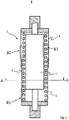
- figure 1 shows a schematic sectional view of a piston-cylinder unit 1 according to the invention, comprising a cylinder 2, a spring 3, an outer spring sleeve 4 and an inner spring sleeve 5.
- the two spring sleeves 4, 5 are arranged concentrically around the centrally arranged cylinder 2.
- the spring 3 is supported and guided between the two partially interlocking spring sleeves 4, 5 and the cylinder 2.
- the outer spring sleeve 4 has a larger inner diameter than the outer diameter of the inner spring sleeve 5, as a result of which the inner spring sleeve 5 can penetrate further into the outer spring sleeve 4 when the piston-cylinder unit 1 is loaded.
- a gas pressure spring can be arranged inside the cylinder 2, for example, or the cylinder 2 can be part of a gas pressure spring.
- the cylinder 2 can also consist of several cylinder segments, which can partially penetrate into each other in order to shorten or lengthen the cylinder 2. For the sake of simplicity, the cylinder 2 is shown here as one piece.
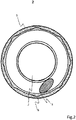
- figure 2 shows a sectional view along the section plane AA of FIG figure 1 .
- An embodiment of the invention is shown here only as an example, which has only axial grooves 6 in the inner spring sleeve 5 .
- the axial grooves in the inner surface of the sleeve reduce the total area of the spring sleeve that is available as a friction partner with the spring 3 to be guided.
- the spring 3 is represented here by a circular ring with a hatched section surface in order to illustrate the reduction in the friction surface with the inner spring sleeve 5 .
- the dotted lines represent the course of an alternative inner spring sleeve 5 without axial grooves 6.
- the axial grooves 6 also serve as a reservoir for a lubricant used in the piston-cylinder unit 1 .
- the grooves 6 retain part of the lubricant due to surface tension effects of the lubricant, even if the rest of the lubricant collects at the other end of the piston-cylinder unit 1 by gravity. This effect can be optimized by matching the geometric dimensions of the grooves to the lubricant.
- Figures 3 - 4 show simplified schematic sectional views of the plane areas B1, B2 and B3 of FIG figure 1 .
- the structures shown can therefore correspond to the contact area between the spring 3 and the inner spring sleeve 5 (B1) or the spring 3 and the outer spring sleeve 4 (B2) or the spring 3 and the cylinder 2 (B3).
- figure 3 shows a schematic sectional view of a contact area between the spring 3 and the surface of one of the spring sleeves 4, 5 or the cylinder 2 in the area of an axial groove 6.
- the spring 3 is in contact with the friction partner outside the groove area while it is shown in the area is not in direct contact.
- the total area of the spring sleeve 4, 5 or of the cylinder 2, which is available as a friction partner with the spring 3, is therefore reduced.
- a lubricant can also be introduced into the axial grooves 6 .
- the grooves then act as a reservoir for the lubricant and prevent the lubricant from collecting completely at one end of the piston-cylinder unit 1 when the piston-cylinder unit is idle for a long time.
- the axial groove 6 in this embodiment has a width along the axial direction (in Figs Figures 3-4 each in horizontal direction) varying depth.
- the depth of the groove 6 varies between a smallest depth H2 at a groove maximum 7 and a greatest depth H3 at a groove minimum 8.
- the axial groove 6 has a periodically varying depth, for example with a sinusoidal profile.
- FIG figure 4 shows yet another schematic sectional view of a contact area between the spring 3 and the surface of one of the spring sleeves 4, 5 or the cylinder 2 in the area of an axial groove 6.
- the axial groove 6 has a varying depth in the axial direction. The depth of the groove 6 varies between a minimum depth H2 at a groove maximum 7 and a maximum depth H3 at a groove minimum 8.
- the spring sleeve(s) 4, 5 and/or the cylinder 2 have at least two layers in this embodiment.
- the outer spring sleeve 4 and/or the inner spring sleeve 5 has a sleeve base layer 9 and a sleeve surface layer 10 and/or the cylinder has a cylinder base layer 11 and a cylinder surface layer 12 .
- the axial groove 6 is located entirely in the sleeve surface layer 10 or the cylinder surface layer 12 .
- the axial groove 6 can be introduced, for example, when the sleeve surface layer 10 or the cylinder surface layer 12 is applied to the respective base layer 9, 11.
- the respective base layer 9, 11 can consist of a mechanically particularly resistant and stable material, for example glass fiber reinforced polyamide.
- the respective surface layer 10, 12 can consist of a material with reduced friction compared to the material of the spring 3 (for example spring steel), for example a plastic mixture comprising polyamide and additives of polytetrafluoroethylene.
- the axial groove 6 has a periodically varying depth, for example with a sinusoidal profile.
Landscapes
- Engineering & Computer Science (AREA)
- General Engineering & Computer Science (AREA)
- Mechanical Engineering (AREA)
- Chemical & Material Sciences (AREA)
- Health & Medical Sciences (AREA)
- Chemical Kinetics & Catalysis (AREA)
- Medicinal Chemistry (AREA)
- Polymers & Plastics (AREA)
- Organic Chemistry (AREA)
- Pistons, Piston Rings, And Cylinders (AREA)
- Fluid-Damping Devices (AREA)
- Springs (AREA)
Claims (8)
- Unité piston-cylindre (1), comprenant :- un cylindre (2),- un ressort (3) disposé concentriquement autour du cylindre (2),- une douille à ressort intérieure (5) et une douille à ressort extérieure (4) disposées concentriquement autour du ressort (2),le cylindre (2) et le ressort (3) étant disposés à l'intérieur de la douille à ressort intérieur (5) et de la douille à ressort extérieur (4), et- la douille à ressort intérieure (5) et/ou- la douille à ressort extérieure (4) et/ou- le cylindre (2)ayant un certain nombre de rainures (6) sur une surface faisant face au ressort, un axe longitudinal des rainures (6) étant aligné dans une direction axiale parallèle à une trajectoire de course de l'unité piston-cylindre,caractérisé en ce qu'une profondeur des rainures (6) varie dans la direction axiale.
- Unité piston-cylindre (1) selon la revendication 1,caractérisé en ce queau moins une surface- de la douille à ressort intérieure (5) et/ou- de la douille à ressort extérieure (4) et/ou- du cylindre (2)est optimisé par rapport au frottement envers le matériau du ressort (3) par le choix du matériau d'une couche de surface de cylindre (12) du cylindre (2) et/ou d'une couche de surface de douille (10) de la douille à ressort intérieure (5) et/ou d'une couche de surface de douille (10) de la douille à ressort externe (4).
- Unité piston-cylindre (1) selon la revendication 1 ou 2,
caractérisé en ce que
la douille à ressort intérieure (5) et/ou la douille à ressort extérieure (4) est faite d'un mélange plastique comprenant un plastique, de préférence du polyamide, et de préférence des additifs- de polytétrafluoroéthylène, la proportion de polytétrafluoroéthylène étant de préférence comprise entre 10% et 30%, ou- de polyamide renforcé, de préférence renforcé de fibres de carbone, de verre et/ou de plastique. - Unité piston-cylindre (1) selon une des revendications 1 à 3,
caractérisé en ce que
la douille à ressort intérieure (5) et/ou la douille à ressort extérieure (4) comprend une couche de base de douille (9) cylindrique et une couche de surface de douille (10), les rainures (6) étant agencées dans la couche de surface de douille (10), et la couche de base de douille (9) et la couche de surface de douille (10) étant constituée de différents matériaux - Unité piston-cylindre (1) selon une des revendications 1 à 4,
caractérisé en ce que
le cylindre (2) comprend une couche de base de cylindre (11) cylindrique et une couche de surface de cylindre (12), les rainures (6) étant agencées dans la couche de surface de cylindre (12), et la couche de base de cylindre (11) et la couche de surface de cylindre (12) étant constituée de différents matériaux. - Procédé de fabrication d'une unité piston-cylindre (1), comprenant :- un cylindre (2),- un ressort (3) disposé concentriquement autour du cylindre (2),- une douille à ressort intérieure (5) et une douille à ressort extérieure (4) disposées concentriquement autour du ressort (3),le procédé comprenant les étapes suivantes :
Faire un certain nombre de rainures (6) dans :- la douille à ressort intérieure (5) et/ou- la douille à ressort extérieure (4) et/ou- le cylindre (2)sur une surface faisant face au ressort (3), de préférence par moulage par injection, par un processus additif ou par un processus soustractif,les rainures (6) étant introduites avec un axe longitudinal aligné dans une direction axiale parallèle à une trajectoire de course de l'unité piston-cylindre, caractérisé en ce queles rainures (6) sont faites avec une profondeur variable dans la direction axiale. - Procédé selon la revendication 6 :
caractérisé par l'étape suivante :
Fabriquer la douille à ressort intérieure (5) et/ou de la douille à ressort extérieure (4) par revêtement d'une couche de base de douille (9) cylindrique avec une couche de surface de douille (10), les rainures (6) étant faites dans la couche de surface de douille (10). - Procédé selon une des revendications 6 à 7 :
caractérisé par l'étape suivante :
Fabriquer le cylindre (2) par revêtement d'une couche de base de cylindre (11) cylindrique avec une couche de surface de cylindre (12), les rainures (6) étant faites dans la couche de surface de cylindre (12).
Applications Claiming Priority (1)
| Application Number | Priority Date | Filing Date | Title |
|---|---|---|---|
| DE102017129539.9A DE102017129539A1 (de) | 2017-12-12 | 2017-12-12 | Federhülse, Zylinder, Kolbenzylindereinheit und Verfahren zur Herstellung einer Kolbenzylindereinheit |
Publications (2)
| Publication Number | Publication Date |
|---|---|
| EP3499083A1 EP3499083A1 (fr) | 2019-06-19 |
| EP3499083B1 true EP3499083B1 (fr) | 2022-06-08 |
Family
ID=64664952
Family Applications (1)
| Application Number | Title | Priority Date | Filing Date |
|---|---|---|---|
| EP18211811.7A Active EP3499083B1 (fr) | 2017-12-12 | 2018-12-12 | Douille à ressort, cylindre, unité piston-cylindre et procédé de fabrication d'une unité piston-cylindre |
Country Status (7)
| Country | Link |
|---|---|
| US (1) | US20190178328A1 (fr) |
| EP (1) | EP3499083B1 (fr) |
| JP (1) | JP7199213B2 (fr) |
| KR (1) | KR102641733B1 (fr) |
| CN (1) | CN110030311B (fr) |
| DE (1) | DE102017129539A1 (fr) |
| ES (1) | ES2926128T3 (fr) |
Families Citing this family (7)
| Publication number | Priority date | Publication date | Assignee | Title |
|---|---|---|---|---|
| DE102018123186A1 (de) * | 2018-09-20 | 2020-03-26 | U-Shin Deutschland Zugangssysteme Gmbh | Unterstützungselement für ein Kraftfahrzeug |
| US11598388B2 (en) * | 2019-09-06 | 2023-03-07 | Pratt & Miller Engineering And Fabrication, Llc | Adaptive energy absorber for structural isolation and injury mitigation |
| CN112674543B (zh) * | 2019-10-17 | 2024-07-26 | 厦门新技术集成有限公司 | 用于家具的弹性模块和弹性垫 |
| CN112610645A (zh) * | 2020-12-28 | 2021-04-06 | 浙江聚力智能机械设备有限公司 | 一种抗非工作向形变的高精度机械弹簧 |
| US20240125177A1 (en) * | 2022-10-14 | 2024-04-18 | Ballymore Company, Inc. | Gas spring supported, bushing guided caster assembly for rolling ladders and ladders having same |
| US20240344392A1 (en) * | 2023-04-13 | 2024-10-17 | Werner Co. | Extension Ladder Accessory |
| DE102023134976B3 (de) | 2023-12-13 | 2025-03-27 | Edscha Mechatronics Solutions GmbH | Akustisch optimierte Stellvorrichtung |
Family Cites Families (20)
| Publication number | Priority date | Publication date | Assignee | Title |
|---|---|---|---|---|
| GB811556A (en) * | 1957-08-12 | 1959-04-08 | Woodhead Monroe Ltd | Improvements in or relating to suspension units |
| NL7810750A (nl) * | 1977-11-04 | 1979-05-08 | Girling Ltd | Ondersteuningseenheid voor voertuig. |
| AT372314B (de) * | 1981-07-03 | 1983-09-26 | Supervis Ets | Lenkspindel fuer lenkvorrichtungen bei kraftfahrzeugen |
| JPS6054851U (ja) * | 1983-09-21 | 1985-04-17 | 川崎重工業株式会社 | リヤサスペンシヨン |
| JP2585423Y2 (ja) * | 1993-04-02 | 1998-11-18 | カヤバ工業株式会社 | ガススプリング装置 |
| DE19646939C2 (de) * | 1996-11-13 | 2000-04-06 | Bayerische Motoren Werke Ag | Federsystem für eine schwenkbare Klappe eines Kraftfahrzeugs |
| DE29913854U1 (de) * | 1999-08-09 | 1999-10-07 | Arturo Salice S.P.A., Novedrate, Como | Bremsverzögerungsvorrichtung für Türen, Fenster o.dgl. |
| DE10147229B4 (de) * | 2001-09-14 | 2004-05-13 | Innotec Forschungs- Und Entwicklungs-Gmbh | Zugfeder für Klappe an einem Kraftfahrzeug |
| DE10158545B4 (de) * | 2001-11-29 | 2004-05-19 | Gkn Driveline Deutschland Gmbh | Längsverschiebeeinheit mit hohlem Profilzapfen |
| JP2005001306A (ja) * | 2003-06-13 | 2005-01-06 | Toray Ind Inc | 繊維強化樹脂成形体の製造方法およびその製造装置 |
| DE102005007741B4 (de) | 2005-02-18 | 2010-11-11 | Stabilus Gmbh | Kolbenzylindereinheit mit einer Schraubendruckfeder |
| DE202005008222U1 (de) * | 2005-05-25 | 2006-01-26 | Innotec Forschungs- Und Entwicklungs-Gmbh | Federsatz für einen teleskopischen Klappenantrieb |
| JP4683634B2 (ja) * | 2005-09-20 | 2011-05-18 | カヤバ工業株式会社 | バネ力調整構造 |
| DE202006015153U1 (de) * | 2006-10-10 | 2008-02-28 | Kiekert Ag | Klappenantrieb für insbesondere Kraftfahrzeuge |
| ATE510990T1 (de) * | 2007-09-11 | 2011-06-15 | Valeo Sicherheitssysteme Gmbh | Antriebseinrichtung für eine kraftfahrzeugtür |
| JP5279742B2 (ja) * | 2010-02-08 | 2013-09-04 | 株式会社東京発条製作所 | コイルスプリングの折損防止方法 |
| KR20110008617U (ko) * | 2010-03-03 | 2011-09-09 | 윤성렬 | 스프링 고정구 |
| GB2519252B (en) * | 2012-08-07 | 2019-03-20 | Piolax Inc | Damper |
| JP2017172201A (ja) | 2016-03-23 | 2017-09-28 | アイシン精機株式会社 | 車両用ドア開閉装置 |
| CN106697071A (zh) * | 2016-11-15 | 2017-05-24 | 浙江众泰汽车制造有限公司 | 一种汽车尾门电动撑杆结构 |
-
2017
- 2017-12-12 DE DE102017129539.9A patent/DE102017129539A1/de not_active Withdrawn
-
2018
- 2018-12-06 US US16/211,565 patent/US20190178328A1/en not_active Abandoned
- 2018-12-10 KR KR1020180157974A patent/KR102641733B1/ko active Active
- 2018-12-10 JP JP2018230747A patent/JP7199213B2/ja active Active
- 2018-12-12 CN CN201811516909.7A patent/CN110030311B/zh active Active
- 2018-12-12 EP EP18211811.7A patent/EP3499083B1/fr active Active
- 2018-12-12 ES ES18211811T patent/ES2926128T3/es active Active
Also Published As
| Publication number | Publication date |
|---|---|
| KR102641733B1 (ko) | 2024-02-27 |
| ES2926128T3 (es) | 2022-10-24 |
| EP3499083A1 (fr) | 2019-06-19 |
| KR20190070287A (ko) | 2019-06-20 |
| DE102017129539A1 (de) | 2019-06-13 |
| JP2019105373A (ja) | 2019-06-27 |
| CN110030311B (zh) | 2021-07-30 |
| CN110030311A (zh) | 2019-07-19 |
| US20190178328A1 (en) | 2019-06-13 |
| JP7199213B2 (ja) | 2023-01-05 |
Similar Documents
| Publication | Publication Date | Title |
|---|---|---|
| EP3499083B1 (fr) | Douille à ressort, cylindre, unité piston-cylindre et procédé de fabrication d'une unité piston-cylindre | |
| EP3724526B1 (fr) | Rail télescopique | |
| EP3044840A2 (fr) | Dispositif de dérivation | |
| DE102015209598A1 (de) | Planetenwälzgewindetrieb | |
| DE102014221135B3 (de) | Kugelgewindemutter | |
| EP1644567B1 (fr) | Amortisseur a friction notamment destine a des lave-linge a tambour | |
| DE102008037208A1 (de) | Kabelhülle, Kabel mit Kabelhülle | |
| DE102012200676B4 (de) | Riemenspanner | |
| DE102008019786B3 (de) | Betätigungszug mit kunststoffummanteltem Innenzug | |
| DE102018118944B4 (de) | Druckfeder zur Verwendung in einer Federstütze sowie Federstütze mit einer solchen Druckfeder | |
| DE10327461B4 (de) | Kettenrad eines Kettengetriebes | |
| DE102016201100B4 (de) | Gleitlagerring und Aktuator mit Gleitlagerring | |
| EP4004387B1 (fr) | Élément de fixation et procédé de fabrication | |
| DE102014223164B4 (de) | Dichtungsführungseinheit | |
| DE202006015585U1 (de) | Zwei-Komponenten Seilumlenkrolle | |
| DE102010028536B4 (de) | Schwingungsdämpfer mit gleitend gelagertem Federführungselement | |
| DE102016202670A1 (de) | Wälzlagerkäfig für ein Schrägkugellager | |
| LU103051B1 (de) | Radialkolbenverdichter, sowie Verfahren zur Montage eines Radialkolbenverdichters | |
| DE102011013035A1 (de) | Antriebskabel | |
| DE102012213028A1 (de) | Elastomerlager, insbesondere Achsträgerlager für ein Kraftfahrzeug | |
| DE102017114219A1 (de) | Wälzkörperkäfig | |
| DE102022133721A1 (de) | Radialkolbenverdichter, sowie Verfahren zur Montage eines Radialkolbenverdichters | |
| DE102012021504A1 (de) | Ringförmiges Federelement | |
| DE102023001741A1 (de) | Wälzkörperkäfig und Verschiebeinheit | |
| EP3543558A1 (fr) | Guidage de tige de piston |
Legal Events
| Date | Code | Title | Description |
|---|---|---|---|
| PUAI | Public reference made under article 153(3) epc to a published international application that has entered the european phase |
Free format text: ORIGINAL CODE: 0009012 |
|
| STAA | Information on the status of an ep patent application or granted ep patent |
Free format text: STATUS: THE APPLICATION HAS BEEN PUBLISHED |
|
| AK | Designated contracting states |
Kind code of ref document: A1 Designated state(s): AL AT BE BG CH CY CZ DE DK EE ES FI FR GB GR HR HU IE IS IT LI LT LU LV MC MK MT NL NO PL PT RO RS SE SI SK SM TR |
|
| AX | Request for extension of the european patent |
Extension state: BA ME |
|
| STAA | Information on the status of an ep patent application or granted ep patent |
Free format text: STATUS: REQUEST FOR EXAMINATION WAS MADE |
|
| 17P | Request for examination filed |
Effective date: 20191204 |
|
| RBV | Designated contracting states (corrected) |
Designated state(s): AL AT BE BG CH CY CZ DE DK EE ES FI FR GB GR HR HU IE IS IT LI LT LU LV MC MK MT NL NO PL PT RO RS SE SI SK SM TR |
|
| GRAP | Despatch of communication of intention to grant a patent |
Free format text: ORIGINAL CODE: EPIDOSNIGR1 |
|
| STAA | Information on the status of an ep patent application or granted ep patent |
Free format text: STATUS: GRANT OF PATENT IS INTENDED |
|
| INTG | Intention to grant announced |
Effective date: 20220119 |
|
| GRAS | Grant fee paid |
Free format text: ORIGINAL CODE: EPIDOSNIGR3 |
|
| GRAA | (expected) grant |
Free format text: ORIGINAL CODE: 0009210 |
|
| STAA | Information on the status of an ep patent application or granted ep patent |
Free format text: STATUS: THE PATENT HAS BEEN GRANTED |
|
| AK | Designated contracting states |
Kind code of ref document: B1 Designated state(s): AL AT BE BG CH CY CZ DE DK EE ES FI FR GB GR HR HU IE IS IT LI LT LU LV MC MK MT NL NO PL PT RO RS SE SI SK SM TR |
|
| REG | Reference to a national code |
Ref country code: AT Ref legal event code: REF Ref document number: 1497136 Country of ref document: AT Kind code of ref document: T Effective date: 20220615 Ref country code: CH Ref legal event code: EP |
|
| REG | Reference to a national code |
Ref country code: DE Ref legal event code: R096 Ref document number: 502018009857 Country of ref document: DE |
|
| REG | Reference to a national code |
Ref country code: IE Ref legal event code: FG4D Free format text: LANGUAGE OF EP DOCUMENT: GERMAN |
|
| REG | Reference to a national code |
Ref country code: LT Ref legal event code: MG9D |
|
| REG | Reference to a national code |
Ref country code: NL Ref legal event code: MP Effective date: 20220608 |
|
| REG | Reference to a national code |
Ref country code: ES Ref legal event code: FG2A Ref document number: 2926128 Country of ref document: ES Kind code of ref document: T3 Effective date: 20221024 |
|
| PG25 | Lapsed in a contracting state [announced via postgrant information from national office to epo] |
Ref country code: SE Free format text: LAPSE BECAUSE OF FAILURE TO SUBMIT A TRANSLATION OF THE DESCRIPTION OR TO PAY THE FEE WITHIN THE PRESCRIBED TIME-LIMIT Effective date: 20220608 Ref country code: NO Free format text: LAPSE BECAUSE OF FAILURE TO SUBMIT A TRANSLATION OF THE DESCRIPTION OR TO PAY THE FEE WITHIN THE PRESCRIBED TIME-LIMIT Effective date: 20220908 Ref country code: LT Free format text: LAPSE BECAUSE OF FAILURE TO SUBMIT A TRANSLATION OF THE DESCRIPTION OR TO PAY THE FEE WITHIN THE PRESCRIBED TIME-LIMIT Effective date: 20220608 Ref country code: HR Free format text: LAPSE BECAUSE OF FAILURE TO SUBMIT A TRANSLATION OF THE DESCRIPTION OR TO PAY THE FEE WITHIN THE PRESCRIBED TIME-LIMIT Effective date: 20220608 Ref country code: GR Free format text: LAPSE BECAUSE OF FAILURE TO SUBMIT A TRANSLATION OF THE DESCRIPTION OR TO PAY THE FEE WITHIN THE PRESCRIBED TIME-LIMIT Effective date: 20220909 Ref country code: FI Free format text: LAPSE BECAUSE OF FAILURE TO SUBMIT A TRANSLATION OF THE DESCRIPTION OR TO PAY THE FEE WITHIN THE PRESCRIBED TIME-LIMIT Effective date: 20220608 Ref country code: BG Free format text: LAPSE BECAUSE OF FAILURE TO SUBMIT A TRANSLATION OF THE DESCRIPTION OR TO PAY THE FEE WITHIN THE PRESCRIBED TIME-LIMIT Effective date: 20220908 |
|
| PG25 | Lapsed in a contracting state [announced via postgrant information from national office to epo] |
Ref country code: RS Free format text: LAPSE BECAUSE OF FAILURE TO SUBMIT A TRANSLATION OF THE DESCRIPTION OR TO PAY THE FEE WITHIN THE PRESCRIBED TIME-LIMIT Effective date: 20220608 Ref country code: LV Free format text: LAPSE BECAUSE OF FAILURE TO SUBMIT A TRANSLATION OF THE DESCRIPTION OR TO PAY THE FEE WITHIN THE PRESCRIBED TIME-LIMIT Effective date: 20220608 |
|
| PG25 | Lapsed in a contracting state [announced via postgrant information from national office to epo] |
Ref country code: NL Free format text: LAPSE BECAUSE OF FAILURE TO SUBMIT A TRANSLATION OF THE DESCRIPTION OR TO PAY THE FEE WITHIN THE PRESCRIBED TIME-LIMIT Effective date: 20220608 |
|
| PG25 | Lapsed in a contracting state [announced via postgrant information from national office to epo] |
Ref country code: SM Free format text: LAPSE BECAUSE OF FAILURE TO SUBMIT A TRANSLATION OF THE DESCRIPTION OR TO PAY THE FEE WITHIN THE PRESCRIBED TIME-LIMIT Effective date: 20220608 Ref country code: SK Free format text: LAPSE BECAUSE OF FAILURE TO SUBMIT A TRANSLATION OF THE DESCRIPTION OR TO PAY THE FEE WITHIN THE PRESCRIBED TIME-LIMIT Effective date: 20220608 Ref country code: RO Free format text: LAPSE BECAUSE OF FAILURE TO SUBMIT A TRANSLATION OF THE DESCRIPTION OR TO PAY THE FEE WITHIN THE PRESCRIBED TIME-LIMIT Effective date: 20220608 Ref country code: PT Free format text: LAPSE BECAUSE OF FAILURE TO SUBMIT A TRANSLATION OF THE DESCRIPTION OR TO PAY THE FEE WITHIN THE PRESCRIBED TIME-LIMIT Effective date: 20221010 Ref country code: EE Free format text: LAPSE BECAUSE OF FAILURE TO SUBMIT A TRANSLATION OF THE DESCRIPTION OR TO PAY THE FEE WITHIN THE PRESCRIBED TIME-LIMIT Effective date: 20220608 Ref country code: CZ Free format text: LAPSE BECAUSE OF FAILURE TO SUBMIT A TRANSLATION OF THE DESCRIPTION OR TO PAY THE FEE WITHIN THE PRESCRIBED TIME-LIMIT Effective date: 20220608 |
|
| PGFP | Annual fee paid to national office [announced via postgrant information from national office to epo] |
Ref country code: GB Payment date: 20221222 Year of fee payment: 5 Ref country code: FR Payment date: 20221222 Year of fee payment: 5 |
|
| PG25 | Lapsed in a contracting state [announced via postgrant information from national office to epo] |
Ref country code: PL Free format text: LAPSE BECAUSE OF FAILURE TO SUBMIT A TRANSLATION OF THE DESCRIPTION OR TO PAY THE FEE WITHIN THE PRESCRIBED TIME-LIMIT Effective date: 20220608 Ref country code: IS Free format text: LAPSE BECAUSE OF FAILURE TO SUBMIT A TRANSLATION OF THE DESCRIPTION OR TO PAY THE FEE WITHIN THE PRESCRIBED TIME-LIMIT Effective date: 20221008 |
|
| REG | Reference to a national code |
Ref country code: DE Ref legal event code: R097 Ref document number: 502018009857 Country of ref document: DE |
|
| PG25 | Lapsed in a contracting state [announced via postgrant information from national office to epo] |
Ref country code: AL Free format text: LAPSE BECAUSE OF FAILURE TO SUBMIT A TRANSLATION OF THE DESCRIPTION OR TO PAY THE FEE WITHIN THE PRESCRIBED TIME-LIMIT Effective date: 20220608 |
|
| PLBE | No opposition filed within time limit |
Free format text: ORIGINAL CODE: 0009261 |
|
| STAA | Information on the status of an ep patent application or granted ep patent |
Free format text: STATUS: NO OPPOSITION FILED WITHIN TIME LIMIT |
|
| PG25 | Lapsed in a contracting state [announced via postgrant information from national office to epo] |
Ref country code: DK Free format text: LAPSE BECAUSE OF FAILURE TO SUBMIT A TRANSLATION OF THE DESCRIPTION OR TO PAY THE FEE WITHIN THE PRESCRIBED TIME-LIMIT Effective date: 20220608 |
|
| PGFP | Annual fee paid to national office [announced via postgrant information from national office to epo] |
Ref country code: ES Payment date: 20230228 Year of fee payment: 5 |
|
| 26N | No opposition filed |
Effective date: 20230310 |
|
| PG25 | Lapsed in a contracting state [announced via postgrant information from national office to epo] |
Ref country code: SI Free format text: LAPSE BECAUSE OF FAILURE TO SUBMIT A TRANSLATION OF THE DESCRIPTION OR TO PAY THE FEE WITHIN THE PRESCRIBED TIME-LIMIT Effective date: 20220608 |
|
| PGFP | Annual fee paid to national office [announced via postgrant information from national office to epo] |
Ref country code: IT Payment date: 20221228 Year of fee payment: 5 |
|
| P01 | Opt-out of the competence of the unified patent court (upc) registered |
Effective date: 20230509 |
|
| REG | Reference to a national code |
Ref country code: CH Ref legal event code: PL |
|
| REG | Reference to a national code |
Ref country code: BE Ref legal event code: MM Effective date: 20221231 |
|
| PG25 | Lapsed in a contracting state [announced via postgrant information from national office to epo] |
Ref country code: LU Free format text: LAPSE BECAUSE OF NON-PAYMENT OF DUE FEES Effective date: 20221212 |
|
| PG25 | Lapsed in a contracting state [announced via postgrant information from national office to epo] |
Ref country code: LI Free format text: LAPSE BECAUSE OF NON-PAYMENT OF DUE FEES Effective date: 20221231 Ref country code: IE Free format text: LAPSE BECAUSE OF NON-PAYMENT OF DUE FEES Effective date: 20221212 Ref country code: CH Free format text: LAPSE BECAUSE OF NON-PAYMENT OF DUE FEES Effective date: 20221231 |
|
| PG25 | Lapsed in a contracting state [announced via postgrant information from national office to epo] |
Ref country code: BE Free format text: LAPSE BECAUSE OF NON-PAYMENT OF DUE FEES Effective date: 20221231 |
|
| PG25 | Lapsed in a contracting state [announced via postgrant information from national office to epo] |
Ref country code: HU Free format text: LAPSE BECAUSE OF FAILURE TO SUBMIT A TRANSLATION OF THE DESCRIPTION OR TO PAY THE FEE WITHIN THE PRESCRIBED TIME-LIMIT; INVALID AB INITIO Effective date: 20181212 |
|
| PG25 | Lapsed in a contracting state [announced via postgrant information from national office to epo] |
Ref country code: CY Free format text: LAPSE BECAUSE OF FAILURE TO SUBMIT A TRANSLATION OF THE DESCRIPTION OR TO PAY THE FEE WITHIN THE PRESCRIBED TIME-LIMIT Effective date: 20220608 |
|
| PG25 | Lapsed in a contracting state [announced via postgrant information from national office to epo] |
Ref country code: MK Free format text: LAPSE BECAUSE OF FAILURE TO SUBMIT A TRANSLATION OF THE DESCRIPTION OR TO PAY THE FEE WITHIN THE PRESCRIBED TIME-LIMIT Effective date: 20220608 |
|
| PG25 | Lapsed in a contracting state [announced via postgrant information from national office to epo] |
Ref country code: MC Free format text: LAPSE BECAUSE OF FAILURE TO SUBMIT A TRANSLATION OF THE DESCRIPTION OR TO PAY THE FEE WITHIN THE PRESCRIBED TIME-LIMIT Effective date: 20220608 |
|
| PG25 | Lapsed in a contracting state [announced via postgrant information from national office to epo] |
Ref country code: MC Free format text: LAPSE BECAUSE OF FAILURE TO SUBMIT A TRANSLATION OF THE DESCRIPTION OR TO PAY THE FEE WITHIN THE PRESCRIBED TIME-LIMIT Effective date: 20220608 |
|
| GBPC | Gb: european patent ceased through non-payment of renewal fee |
Effective date: 20231212 |
|
| PG25 | Lapsed in a contracting state [announced via postgrant information from national office to epo] |
Ref country code: MT Free format text: LAPSE BECAUSE OF FAILURE TO SUBMIT A TRANSLATION OF THE DESCRIPTION OR TO PAY THE FEE WITHIN THE PRESCRIBED TIME-LIMIT Effective date: 20220608 |
|
| PG25 | Lapsed in a contracting state [announced via postgrant information from national office to epo] |
Ref country code: GB Free format text: LAPSE BECAUSE OF NON-PAYMENT OF DUE FEES Effective date: 20231212 |
|
| PG25 | Lapsed in a contracting state [announced via postgrant information from national office to epo] |
Ref country code: FR Free format text: LAPSE BECAUSE OF NON-PAYMENT OF DUE FEES Effective date: 20231231 |
|
| PG25 | Lapsed in a contracting state [announced via postgrant information from national office to epo] |
Ref country code: GB Free format text: LAPSE BECAUSE OF NON-PAYMENT OF DUE FEES Effective date: 20231212 Ref country code: FR Free format text: LAPSE BECAUSE OF NON-PAYMENT OF DUE FEES Effective date: 20231231 |
|
| PG25 | Lapsed in a contracting state [announced via postgrant information from national office to epo] |
Ref country code: BG Free format text: LAPSE BECAUSE OF FAILURE TO SUBMIT A TRANSLATION OF THE DESCRIPTION OR TO PAY THE FEE WITHIN THE PRESCRIBED TIME-LIMIT Effective date: 20220608 |
|
| PG25 | Lapsed in a contracting state [announced via postgrant information from national office to epo] |
Ref country code: BG Free format text: LAPSE BECAUSE OF FAILURE TO SUBMIT A TRANSLATION OF THE DESCRIPTION OR TO PAY THE FEE WITHIN THE PRESCRIBED TIME-LIMIT Effective date: 20220608 |
|
| REG | Reference to a national code |
Ref country code: ES Ref legal event code: FD2A Effective date: 20250127 |
|
| REG | Reference to a national code |
Ref country code: AT Ref legal event code: MM01 Ref document number: 1497136 Country of ref document: AT Kind code of ref document: T Effective date: 20231212 |
|
| PG25 | Lapsed in a contracting state [announced via postgrant information from national office to epo] |
Ref country code: ES Free format text: LAPSE BECAUSE OF NON-PAYMENT OF DUE FEES Effective date: 20231213 |
|
| PG25 | Lapsed in a contracting state [announced via postgrant information from national office to epo] |
Ref country code: AT Free format text: LAPSE BECAUSE OF NON-PAYMENT OF DUE FEES Effective date: 20231212 |
|
| PG25 | Lapsed in a contracting state [announced via postgrant information from national office to epo] |
Ref country code: IT Free format text: LAPSE BECAUSE OF NON-PAYMENT OF DUE FEES Effective date: 20231212 |
|
| PG25 | Lapsed in a contracting state [announced via postgrant information from national office to epo] |
Ref country code: TR Free format text: LAPSE BECAUSE OF FAILURE TO SUBMIT A TRANSLATION OF THE DESCRIPTION OR TO PAY THE FEE WITHIN THE PRESCRIBED TIME-LIMIT Effective date: 20220608 |
|
| PGFP | Annual fee paid to national office [announced via postgrant information from national office to epo] |
Ref country code: DE Payment date: 20251231 Year of fee payment: 8 |
|
| PGFP | Annual fee paid to national office [announced via postgrant information from national office to epo] |
Ref country code: AT Payment date: 20260410 Year of fee payment: 5 |