EP3499110A1 - Luminaire de véhicule - Google Patents
Luminaire de véhicule Download PDFInfo
- Publication number
- EP3499110A1 EP3499110A1 EP17839481.3A EP17839481A EP3499110A1 EP 3499110 A1 EP3499110 A1 EP 3499110A1 EP 17839481 A EP17839481 A EP 17839481A EP 3499110 A1 EP3499110 A1 EP 3499110A1
- Authority
- EP
- European Patent Office
- Prior art keywords
- light
- chip array
- emitting chip
- emitting
- emitting chips
- Prior art date
- Legal status (The legal status is an assumption and is not a legal conclusion. Google has not performed a legal analysis and makes no representation as to the accuracy of the status listed.)
- Withdrawn
Links
Images




Classifications
-
- F—MECHANICAL ENGINEERING; LIGHTING; HEATING; WEAPONS; BLASTING
- F21—LIGHTING
- F21S—NON-PORTABLE LIGHTING DEVICES; SYSTEMS THEREOF; VEHICLE LIGHTING DEVICES SPECIALLY ADAPTED FOR VEHICLE EXTERIORS
- F21S41/00—Illuminating devices specially adapted for vehicle exteriors, e.g. headlamps
- F21S41/10—Illuminating devices specially adapted for vehicle exteriors, e.g. headlamps characterised by the light source
- F21S41/14—Illuminating devices specially adapted for vehicle exteriors, e.g. headlamps characterised by the light source characterised by the type of light source
- F21S41/141—Light emitting diodes [LED]
- F21S41/143—Light emitting diodes [LED] the main emission direction of the LED being parallel to the optical axis of the illuminating device
-
- F—MECHANICAL ENGINEERING; LIGHTING; HEATING; WEAPONS; BLASTING
- F21—LIGHTING
- F21S—NON-PORTABLE LIGHTING DEVICES; SYSTEMS THEREOF; VEHICLE LIGHTING DEVICES SPECIALLY ADAPTED FOR VEHICLE EXTERIORS
- F21S43/00—Signalling devices specially adapted for vehicle exteriors, e.g. brake lamps, direction indicator lights or reversing lights
- F21S43/10—Signalling devices specially adapted for vehicle exteriors, e.g. brake lamps, direction indicator lights or reversing lights characterised by the light source
- F21S43/13—Signalling devices specially adapted for vehicle exteriors, e.g. brake lamps, direction indicator lights or reversing lights characterised by the light source characterised by the type of light source
- F21S43/14—Light emitting diodes [LED]
-
- B—PERFORMING OPERATIONS; TRANSPORTING
- B60—VEHICLES IN GENERAL
- B60Q—ARRANGEMENT OF SIGNALLING OR LIGHTING DEVICES, THE MOUNTING OR SUPPORTING THEREOF OR CIRCUITS THEREFOR, FOR VEHICLES IN GENERAL
- B60Q1/00—Arrangement of optical signalling or lighting devices, the mounting or supporting thereof or circuits therefor
- B60Q1/02—Arrangement of optical signalling or lighting devices, the mounting or supporting thereof or circuits therefor the devices being primarily intended to illuminate the way ahead or to illuminate other areas of way or environments
- B60Q1/04—Arrangement of optical signalling or lighting devices, the mounting or supporting thereof or circuits therefor the devices being primarily intended to illuminate the way ahead or to illuminate other areas of way or environments the devices being headlights
- B60Q1/14—Arrangement of optical signalling or lighting devices, the mounting or supporting thereof or circuits therefor the devices being primarily intended to illuminate the way ahead or to illuminate other areas of way or environments the devices being headlights having dimming means
- B60Q1/1415—Dimming circuits
- B60Q1/1423—Automatic dimming circuits, i.e. switching between high beam and low beam due to change of ambient light or light level in road traffic
- B60Q1/143—Automatic dimming circuits, i.e. switching between high beam and low beam due to change of ambient light or light level in road traffic combined with another condition, e.g. using vehicle recognition from camera images or activation of wipers
-
- F—MECHANICAL ENGINEERING; LIGHTING; HEATING; WEAPONS; BLASTING
- F21—LIGHTING
- F21S—NON-PORTABLE LIGHTING DEVICES; SYSTEMS THEREOF; VEHICLE LIGHTING DEVICES SPECIALLY ADAPTED FOR VEHICLE EXTERIORS
- F21S41/00—Illuminating devices specially adapted for vehicle exteriors, e.g. headlamps
- F21S41/10—Illuminating devices specially adapted for vehicle exteriors, e.g. headlamps characterised by the light source
- F21S41/14—Illuminating devices specially adapted for vehicle exteriors, e.g. headlamps characterised by the light source characterised by the type of light source
- F21S41/141—Light emitting diodes [LED]
-
- F—MECHANICAL ENGINEERING; LIGHTING; HEATING; WEAPONS; BLASTING
- F21—LIGHTING
- F21S—NON-PORTABLE LIGHTING DEVICES; SYSTEMS THEREOF; VEHICLE LIGHTING DEVICES SPECIALLY ADAPTED FOR VEHICLE EXTERIORS
- F21S41/00—Illuminating devices specially adapted for vehicle exteriors, e.g. headlamps
- F21S41/10—Illuminating devices specially adapted for vehicle exteriors, e.g. headlamps characterised by the light source
- F21S41/14—Illuminating devices specially adapted for vehicle exteriors, e.g. headlamps characterised by the light source characterised by the type of light source
- F21S41/141—Light emitting diodes [LED]
- F21S41/151—Light emitting diodes [LED] arranged in one or more lines
-
- F—MECHANICAL ENGINEERING; LIGHTING; HEATING; WEAPONS; BLASTING
- F21—LIGHTING
- F21S—NON-PORTABLE LIGHTING DEVICES; SYSTEMS THEREOF; VEHICLE LIGHTING DEVICES SPECIALLY ADAPTED FOR VEHICLE EXTERIORS
- F21S41/00—Illuminating devices specially adapted for vehicle exteriors, e.g. headlamps
- F21S41/10—Illuminating devices specially adapted for vehicle exteriors, e.g. headlamps characterised by the light source
- F21S41/14—Illuminating devices specially adapted for vehicle exteriors, e.g. headlamps characterised by the light source characterised by the type of light source
- F21S41/141—Light emitting diodes [LED]
- F21S41/151—Light emitting diodes [LED] arranged in one or more lines
- F21S41/153—Light emitting diodes [LED] arranged in one or more lines arranged in a matrix
-
- F—MECHANICAL ENGINEERING; LIGHTING; HEATING; WEAPONS; BLASTING
- F21—LIGHTING
- F21S—NON-PORTABLE LIGHTING DEVICES; SYSTEMS THEREOF; VEHICLE LIGHTING DEVICES SPECIALLY ADAPTED FOR VEHICLE EXTERIORS
- F21S41/00—Illuminating devices specially adapted for vehicle exteriors, e.g. headlamps
- F21S41/20—Illuminating devices specially adapted for vehicle exteriors, e.g. headlamps characterised by refractors, transparent cover plates, light guides or filters
- F21S41/25—Projection lenses
-
- F—MECHANICAL ENGINEERING; LIGHTING; HEATING; WEAPONS; BLASTING
- F21—LIGHTING
- F21S—NON-PORTABLE LIGHTING DEVICES; SYSTEMS THEREOF; VEHICLE LIGHTING DEVICES SPECIALLY ADAPTED FOR VEHICLE EXTERIORS
- F21S41/00—Illuminating devices specially adapted for vehicle exteriors, e.g. headlamps
- F21S41/20—Illuminating devices specially adapted for vehicle exteriors, e.g. headlamps characterised by refractors, transparent cover plates, light guides or filters
- F21S41/25—Projection lenses
- F21S41/255—Lenses with a front view of circular or truncated circular outline
-
- F—MECHANICAL ENGINEERING; LIGHTING; HEATING; WEAPONS; BLASTING
- F21—LIGHTING
- F21S—NON-PORTABLE LIGHTING DEVICES; SYSTEMS THEREOF; VEHICLE LIGHTING DEVICES SPECIALLY ADAPTED FOR VEHICLE EXTERIORS
- F21S41/00—Illuminating devices specially adapted for vehicle exteriors, e.g. headlamps
- F21S41/60—Illuminating devices specially adapted for vehicle exteriors, e.g. headlamps characterised by a variable light distribution
- F21S41/65—Illuminating devices specially adapted for vehicle exteriors, e.g. headlamps characterised by a variable light distribution by acting on light sources
- F21S41/663—Illuminating devices specially adapted for vehicle exteriors, e.g. headlamps characterised by a variable light distribution by acting on light sources by switching light sources
-
- F—MECHANICAL ENGINEERING; LIGHTING; HEATING; WEAPONS; BLASTING
- F21—LIGHTING
- F21S—NON-PORTABLE LIGHTING DEVICES; SYSTEMS THEREOF; VEHICLE LIGHTING DEVICES SPECIALLY ADAPTED FOR VEHICLE EXTERIORS
- F21S45/00—Arrangements within vehicle lighting devices specially adapted for vehicle exteriors, for purposes other than emission or distribution of light
- F21S45/40—Cooling of lighting devices
-
- B—PERFORMING OPERATIONS; TRANSPORTING
- B60—VEHICLES IN GENERAL
- B60Q—ARRANGEMENT OF SIGNALLING OR LIGHTING DEVICES, THE MOUNTING OR SUPPORTING THEREOF OR CIRCUITS THEREFOR, FOR VEHICLES IN GENERAL
- B60Q2300/00—Indexing codes for automatically adjustable headlamps or automatically dimmable headlamps
- B60Q2300/40—Indexing codes relating to other road users or special conditions
- B60Q2300/45—Special conditions, e.g. pedestrians, road signs or potential dangers
-
- F—MECHANICAL ENGINEERING; LIGHTING; HEATING; WEAPONS; BLASTING
- F21—LIGHTING
- F21W—INDEXING SCHEME ASSOCIATED WITH SUBCLASSES F21K, F21L, F21S and F21V, RELATING TO USES OR APPLICATIONS OF LIGHTING DEVICES OR SYSTEMS
- F21W2102/00—Exterior vehicle lighting devices for illuminating purposes
- F21W2102/10—Arrangement or contour of the emitted light
- F21W2102/13—Arrangement or contour of the emitted light for high-beam region or low-beam region
- F21W2102/135—Arrangement or contour of the emitted light for high-beam region or low-beam region the light having cut-off lines, i.e. clear borderlines between emitted regions and dark regions
- F21W2102/14—Arrangement or contour of the emitted light for high-beam region or low-beam region the light having cut-off lines, i.e. clear borderlines between emitted regions and dark regions having vertical cut-off lines; specially adapted for adaptive high beams, i.e. wherein the beam is broader but avoids glaring other road users
- F21W2102/15—Arrangement or contour of the emitted light for high-beam region or low-beam region the light having cut-off lines, i.e. clear borderlines between emitted regions and dark regions having vertical cut-off lines; specially adapted for adaptive high beams, i.e. wherein the beam is broader but avoids glaring other road users wherein the light is emitted under L-shaped cut-off lines, i.e. vertical and horizontal cutoff lines
-
- F—MECHANICAL ENGINEERING; LIGHTING; HEATING; WEAPONS; BLASTING
- F21—LIGHTING
- F21Y—INDEXING SCHEME ASSOCIATED WITH SUBCLASSES F21K, F21L, F21S and F21V, RELATING TO THE FORM OR THE KIND OF THE LIGHT SOURCES OR OF THE COLOUR OF THE LIGHT EMITTED
- F21Y2105/00—Planar light sources
- F21Y2105/10—Planar light sources comprising a two-dimensional [2D] array of point-like light-generating elements
- F21Y2105/12—Planar light sources comprising a two-dimensional [2D] array of point-like light-generating elements characterised by the geometrical disposition of the light-generating elements, e.g. arranging light-generating elements in differing patterns or densities
-
- F—MECHANICAL ENGINEERING; LIGHTING; HEATING; WEAPONS; BLASTING
- F21—LIGHTING
- F21Y—INDEXING SCHEME ASSOCIATED WITH SUBCLASSES F21K, F21L, F21S and F21V, RELATING TO THE FORM OR THE KIND OF THE LIGHT SOURCES OR OF THE COLOUR OF THE LIGHT EMITTED
- F21Y2115/00—Light-generating elements of semiconductor light sources
- F21Y2115/10—Light-emitting diodes [LED]
Definitions
- the present invention relates to a vehicular lamp.
- Patent Literature 1 discloses a vehicular front light capable of controlling an adaptive driving beam that varies a driving-beam light distribution pattern, to suppress glare light emitted to a leading vehicle.
- Patent Literature 1 Japanese Unexamined Patent Application Publication No. 2013-20709
- An object of the present invention which has been conceived in light of the above-described circumstances, is to provide a vehicular lamp having functionalities more enhanced than those of the related art.
- the present invention is realized by the following constitution.
- a vehicular lamp having functionalities more enhanced than those of the related art can be provided.
- front and “rear” indicate a “forward direction” and a “reverse direction,” respectively, of the vehicle, and “upper,” “lower,” left,” and “right” all indicate directions from the viewpoint of a driver riding in the vehicle.
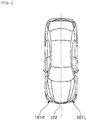
- Vehicular lamps according to the embodiments of the present invention are vehicular front lights (101R, 101L) provided on the left and right sides, respectively, at the front of a vehicle 102 illustrated in FIG. 1 , which will hereinafter simply be referred to as vehicular lamps.
- the right and left vehicular lamps have the same configuration unless otherwise specified to have a configuration for the left vehicular lamp or the right vehicular lamp.
- a vehicular lamp according to the first embodiment includes a housing (not illustrated) open to the front of the vehicle and an outer lens (not illustrated) attached to the housing so as to cover the opening.
- a lamp unit 10 (see FIG. 2 ) is disposed in a lamp chamber defined by the housing and the outer lens.
- FIG. 2 is a perspective view illustrating the main components of the lamp unit 10. As in the subsequent drawings, an X axis indicates the horizontal direction of the vehicle 102, a Y axis indicates the vertical direction of the vehicle 102, and a Z axis indicates a lamp optical axis of a lamp unit.
- the lamp unit 10 includes a light source unit 20 and a lens 21 disposed in front of the light source unit 20.
- the light source unit 20 is disposed on a heat sink, and the lens 21 is also attached to the heat sink via a lens holder.
- FIG. 2 illustrates only the lens 21, which is the part that performs light distribution control
- the vehicular lamp includes, for example, a lens member to be held by the lens holder, the lens member having flanges formed at the two ends thereof in the horizontal direction (the X axis direction) of the lens 21.
- the lens 21 may be attached to the lens holder through any method, such as fixing a circumferential end face of the lens 21 to the lens holder with an adhesive agent, the method not being particularly limited.
- the lens 21 has a rectangular shape in front view and is composed of, for example, an acrylic resin, such as PMMA, transparent resin, such as polycarbonate (PC) or polycyclohexylenedimethylene terephthalate (PCT), or glass.
- an acrylic resin such as PMMA
- transparent resin such as polycarbonate (PC) or polycyclohexylenedimethylene terephthalate (PCT)
- glass glass
- the lens 21 is desirably made of transparent resin.
- acrylic resin having low wavelength dependency of the refractive index and capable of reducing the influence of spectroscopy is desirably used.
- the light source unit 20 includes many light-emitting chips.
- the temperature of the lens 21 may become high.
- the lens 21 be composed of a material having satisfactory heat resistance, such as polycarbonate (PC) or glass.
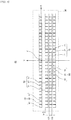
- FIG. 3 is a plan view of the light source unit 20. Note that FIG. 3 is a plan view of the light source unit 20 from the rear side of the vehicle, indicating the external shape of a substrate 30 by dotted lines and mainly illustrating light-emitting chips disposed on the substrate 30.
- the light source unit 20 includes a substrate 30, a first light-emitting chip array 40 including many semiconductor-type first light-emitting chips 41 disposed along the horizontal direction (the X axis direction) on the substrate 30, a second light-emitting chip array 50 including many semiconductor-type second light-emitting chips 51 disposed along the horizontal direction (the X axis direction) on the substrate 30, and a third light-emitting chip array 60 including many semiconductor-type third light-emitting chips 61 disposed along the horizontal direction (the X axis direction) on the substrate 30.
- This embodiment further includes a bottom light-emitting chip array 70 including many semiconductor-type bottom light-emitting chips 71 disposed along a horizontal direction on the substrate 30.
- the first light-emitting chips 41, the second light-emitting chips 51, the third light-emitting chips 61, and the bottom light-emitting chips 71 are LED chips. Alternatively, they may be semiconductor-type light-emitting chips, such as LD chips.
- the substrate 30 be a multilayer wiring board, not a monolayer circuit board, including multiple layers having wiring patterns stacked in the thickness direction, so that many light-emitting chips can be densely arranged.
- a buildup board can be desirably used as the substrate 30, the buildup board including multiple layers having wiring patterns stacked in the thickness direction by alternately forming circuits and substrates on a first substrate on which a first circuit is formed.
- FIG. 4 illustrates light distribution patterns formed on a screen by light from each light-emitting chip array (the first light-emitting chip array 40, the second light-emitting chip array 50, the third light-emitting chip array 60, and the bottom light-emitting chip array 70).
- FIG. 4(a) illustrates the light distribution pattern formed on a screen when the first light-emitting chips 41 in the first light-emitting chip array 40 are all turned on;
- FIG. 4(b) illustrates the light distribution pattern formed on a screen when the second light-emitting chips 51 in the second light-emitting chip array 50 are all turned on;
- FIG. 4(c) illustrates the light distribution pattern formed on a screen when the third light-emitting chips 61 in the third light-emitting chip array 60 are all turned on;
- FIG. 4(d) illustrates the light distribution pattern formed on a screen when the bottom light-emitting chips 71 in the bottom light-emitting chip array 70 are all turned on.
- a VU-VL line indicates a vertical reference line on the screen
- an HL-HR line indicates a horizontal reference line on the screen.
- the VU-VL line indicates a vertical reference line on the screen
- the HL-HR line indicates the horizontal reference line on the screen.
- the first light-emitting chip array 40 is disposed on the substrate 30 such that the center of the first light-emitting chip array 40 in the horizontal direction (the X axis direction) is positioned on or near the lamp optical axis (see the Z axis). Note that the first light-emitting chip array 40 is disposed on the substrate 30 on or near the lamp optical axis (see the Z axis) in view of the vertical direction (the Y axis direction).
- the first light-emitting chip 41 positioned at the center of the first light-emitting chip array 40 in the horizontal direction (the X axis direction) is disposed on or near the lamp optical axis (see the Z axis) on the substrate 30.
- 14 first light-emitting chips 41 are disposed at a constant pitch along the horizontal direction (the X axis direction) toward the left and right, respectively.
- the first light-emitting chip array 40 consists of a total of 29 first light-emitting chips 41.
- the first light-emitting chips 41 may be disposed along the horizontal direction toward the left and right, respectively, in different numbers.
- a light distribution pattern is formed that is substantially symmetrical about the vertical reference line (the VU-VL line) in the horizontal direction and extending across the horizontal reference line (the HL-HR line) in the vertical direction, as illustrated in FIG. 4(a) .
- the light distribution pattern illustrated in FIG. 4(a) is formed by the individual light distribution patterns formed by the light from the corresponding first light-emitting chips 41 overlapping in the horizontal direction with the light distribution patterns adjacent to each other.
- the individual light distribution pattern (see region P1) formed by the light from a first light-emitting chip 41 positioned at the center of the first light-emitting chip array 40 in the horizontal direction is disposed on the vertical reference line (the VU-VL line);
- the individual light distribution pattern (see region P2) formed by the light from a first light-emitting chip 41 immediately on the left of the first light-emitting chip 41 disposed at the center in the horizontal direction is positioned on the right of the vertical reference line (the VU-VL line) in the horizontal direction while overlapping the right-side portion of the light distribution pattern (see region P1) disposed on the vertical reference line (the VU-VL line).
- the individual light distribution pattern (see region P3) formed by the light from a first light-emitting chip 41 immediately on the right of the first light-emitting chip 41 disposed at the center in the horizontal direction is disposed on the left of the vertical reference line (the VU-VL line) in the horizontal direction while overlapping the left-side portion of the light distribution pattern (see region P1) disposed on the vertical reference line (the VU-VL line).
- the regions of the individual light distribution patterns formed by the light from the three first light-emitting chips 41 disposed at and near the center in the horizontal direction are indicated as a region PI, a region P2, and a region P3.
- individual light distribution patterns formed by the light from other first light-emitting chips 41 disposed on the outer left and right sides the first light-emitting chips 41 disposed at and near the center reside adjacent to each other such that the individual light distribution patterns overlap with each other.
- the light from the first light-emitting chip 41 residing farthest right in the horizontal direction forms the farthest left portion of the light distribution pattern in the horizontal direction
- the light from the first light-emitting chip 41 residing farthest left in the horizontal direction forms the farthest right portion of the light distribution pattern in the horizontal direction.
- the second light-emitting chip array 50 is disposed on the substrate 30 such that the center of the second light-emitting chip array 50 in the horizontal direction (the X axis direction) is positioned on or near the vertical line (see the Y axis) extending through the lamp optical axis (see the Z axis) is disposed at a first distance D1 vertically downward from the first light-emitting chip array 40, as illustrated in FIG. 3 .
- the second light-emitting chip array 50 is also disposed on the substrate 30 such that the second light-emitting chip 51 at the center of the second light-emitting chip array 50 in the horizontal direction (the X axis direction) is positioned on or near the vertical line (see the Y axis) extending through the lamp optical axis (see the Z axis). With reference to the second light-emitting chip 51 disposed at the center, 14 second light-emitting chips 51 are disposed at a constant pitch along the horizontal direction (the X axis direction) toward the left and right, respectively.
- the second light-emitting chip array 50 also consists of a total of 29 second light-emitting chips 51, like the first light-emitting chip array 40.
- the second light-emitting chip 51 positioned on or near the vertical line (see the Y axis) extending through the lamp optical axis (see the Z axis) of the second light-emitting chip array 50, different numbers of the second light-emitting chips 51 may be disposed on the left and right sides in the horizontal direction, and/or the number of the second light-emitting chips 51 may be smaller than the number of the first light-emitting chips 41.
- a light distribution pattern is formed that is substantially symmetrical in the horizontal direction about the vertical reference line (the VU-VL line), as illustrated in FIG. 4(b) . Since the second light-emitting chip array 50 is disposed at a large first distance D1 (for example, approximately 0.94 mm) vertically downward from the first light-emitting chip array 40, the lower edge of the light distribution pattern is positioned above the horizontal reference line (the HL-HR line).
- D1 for example, approximately 0.94 mm
- the individual light distribution patterns formed by the light from the second light-emitting chips 51 overlap the adjacent light distribution patterns in the horizontal direction.
- emission of light to a leading vehicle or an oncoming vehicle can be avoided by turning off the second light-emitting chips 51 corresponding to the position of the leading vehicle or the oncoming vehicle in the horizontal direction, thereby suppressing the generation of glare light.
- the third light-emitting chip array 60 is disposed on the substrate 30 such that the center of the third light-emitting chip array 60 in the horizontal direction (the X axis direction) is positioned on or near the vertical line (see the Y axis) extending through the lamp optical axis (see the Z axis) and is disposed at a second distance D2 vertically downward from the second light-emitting chip array 50, as illustrated in FIG. 3 .
- the third light-emitting chip array 60 is also disposed on the substrate 30 such that the third light-emitting chip 61 at the center of the third light-emitting chip array 60 in the horizontal direction (the X axis direction) is positioned on or near the vertical line (see the Y axis) extending through the lamp optical axis (see the Z axis).
- the third light-emitting chip 61 disposed at the center 14 third light-emitting chips 61 are disposed at a constant pitch along the horizontal direction (the X axis direction) toward the left and right, respectively.
- the third light-emitting chip array 60 also consists of a total of 29 third light-emitting chips 61, like the first light-emitting chip array 40 and the second light-emitting chip array 50.
- the third light-emitting chips 61 disposed on or near the vertical line (see the Y axis) extending through the lamp optical axis (see the Z axis) of the third light-emitting chip array 60, different numbers of the third light-emitting chips 61 may be disposed on the left and right sides in the horizontal direction, and/or the number of the third light-emitting chips 61 may be smaller than the number of the second light-emitting chips 51.
- a light distribution pattern is formed that is substantially symmetrical in the horizontal direction about the vertical reference line (the VU-VL line), as illustrated in FIG. 4(c) .
- the third light-emitting chip array 60 is disposed only at a small second distance D2 (for example, approximately 0.24 mm) vertically downward from the second light-emitting chip array 50, the lower edge of the light distribution pattern is positioned slightly vertically above the light distribution pattern (see FIG. 4(b) ) formed by the light from the second light-emitting chip array 50.
- the individual light distribution patterns formed by the light from the third light-emitting chips 61 overlap the adjacent light distribution patterns in the horizontal direction.
- emission of light to a leading vehicle or an oncoming vehicle can be avoided by turning off the third light-emitting chips 61 corresponding to the position of the leading vehicle or the oncoming vehicle in the horizontal direction, thereby suppressing the generation of glare light.
- the main light that acts as glare light to a leading vehicle or an oncoming vehicle is incident on the screen vertically above the horizontal reference line (the HL-HR line).
- the HL-HR line the horizontal reference line
- the positions of the lower edges of the light distribution patterns having lower edges disposed vertically above the horizontal reference line (the HL-HR line) on the screen slightly differ in the vertical direction.
- the light-emitting chips corresponding to the light distribution patterns having lower edges disposed vertically above the roof of the leading vehicle or the oncoming vehicle remain turned on, whereas the light-emitting chips corresponding to the light distribution patterns having lower edges disposed below the roof of the leading vehicle or the oncoming vehicle are turned off, thereby suppressing glare light emitted to the leading vehicle or the oncoming vehicle.
- the bottom light-emitting chip array 70 is also disposed on the substrate 30 such that the center of the bottom light-emitting chip array 70 in the horizontal direction (the X axis direction) is positioned on or near the vertical line (see the Y axis) extending through the lamp optical axis (see the Z axis) and is disposed at a second distance D2 vertically downward from the third light-emitting chip array 60, as illustrated in FIG. 3 .
- the light distribution pattern is substantially symmetrical in the horizontal direction about the vertical reference line (the VU-VL line), like the first light-emitting chip array 40, the second light-emitting chip array 50, and the third light-emitting chip array 60, as illustrated in FIG. 4(d) .
- the bottom light-emitting chip array 70 is disposed only at a small second distance D2 (for example, approximately 0.24 mm) vertically downward from the third light-emitting chip array 60, the lower edge of the light distribution pattern is positioned only slightly vertically above the lower edge of the light distribution pattern (see FIG. 4(c) ) formed by the light from the third light-emitting chip array 60.
- the bottom light-emitting chip array 70 is also disposed on the substrate 30 such that the bottom light-emitting chip 71 at the center of the bottom light-emitting chip array 70 in the horizontal direction (the X axis direction) is positioned on or near the vertical line (see the Y axis) extending through the lamp optical axis (see the Z axis).
- the bottom light-emitting chip 71 disposed at the center 14 bottom light-emitting chips 71 are disposed at a constant pitch along the horizontal direction (the X axis direction) to the left and right, respectively, and a total of 29 bottom light-emitting chips 71 are provided.
- the bottom light-emitting chip 71 disposed on or near the vertical line (see the Y axis) extending through the lamp optical axis (see the Z axis) of the bottom light-emitting chip array 70
- different numbers of the bottom light-emitting chips 71 may be disposed on the left and right sides in the horizontal direction, and/or the number of the bottom light-emitting chips 71 may be smaller than the number of the third light-emitting chips 61.
- a driving-beam light distribution pattern formed by multiplexing light distribution patterns formed of light from corresponding light-emitting chip arrays (the first light-emitting chip array 40, the second light-emitting chip array 50, the third light-emitting chip array 60, and the bottom light-emitting chip array 70) has luminosity that smoothly attenuates in the vertically upward direction.
- the luminescence of the second light-emitting chips 51 of the second light-emitting chip array 50 lower than the luminescence of the first light-emitting chips 41 of the first light-emitting chip array 40, the luminescence of the third light-emitting chips 61 of the third light-emitting chip array 60 lower than the luminescence of the second light-emitting chips 51 of the second light-emitting chip array 50, and the luminescence of the bottom light-emitting chips 71 of the bottom light-emitting chip array 70 lower than the luminescence of the third light-emitting chips 61 of the third light-emitting chip array 60.
- the electrical power supplied to the second light-emitting chips 51, the third light-emitting chips 61, and the bottom light-emitting chips 71 be reduced in order, such that, when the luminescence (output) of the first light-emitting chips 41 is set to 100%, the luminescence (output) of the second light-emitting chips 51 is set to approximately 50%, the luminescence (output) of the third light-emitting chips 61 is set to approximately 35%, and the luminescence (output) of the bottom light-emitting chips 71 is set to approximately 20%.
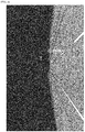
- FIG. 5 illustrates a driving-beam light distribution pattern according to this embodiment on a screen, the driving-beam light distribution pattern being formed by multiplexing the light distribution patterns illustrated in FIG. 4 . Note that the light distribution patterns are indicated by equal luminosity lines in FIG. 5 .
- the light-emitting chips (the first light-emitting chips 41, the second light-emitting chips 51, the third light-emitting chips 61, and the bottom light-emitting chips 71) are in the same arrangement in the horizontal direction in the corresponding light-emitting chip arrays (the first light-emitting chip array 40, the second light-emitting chip array 50, the third light-emitting chip array 60, and the bottom light-emitting chip array 70).
- the widths of the light distribution patterns in the horizontal direction are substantially the same, as illustrated in FIG. 4 .
- the positions of the light distribution patterns on the screen are varied in the vertical direction to appropriately control the positions of the lower edges of the light distribution patterns.
- the driving-beam light distribution pattern formed by the multiplexing the light distribution patterns illustrated in FIG. 4 has a rectangular shape that is wide in the horizontal and vertical directions, as illustrated in FIG. 5 , and achieves a satisfactory driving-beam light distribution pattern having the highest luminescence at the center.
- FIG. 6 illustrates a case in which some of the light-emitting chips are turned off to respond to a leading vehicle or an oncoming vehicle.
- light distribution can be controlled to prevent a region C corresponding to a leading vehicle or an oncoming vehicle from being irradiated with light, as illustrated in FIG. 6 , because light-emitting chip arrays are disposed in other rows in the vertical direction.
- the region C includes a small substantially rectangular segment C1 on the left side in the horizontal direction and a large substantially rectangular segment C2 adjoining the right side of the small substantially rectangular segment C1 in the horizontal direction.
- the small substantially rectangular segment C1 corresponds to a leading vehicle approximately 100 m ahead and is not irradiated with light.
- the large substantially rectangular segment C2 corresponds to an oncoming vehicle approximately 50 m ahead and is not irradiated with light.
- the use of a multilayer wiring board as the substrate 30 prevents the intervals of the light-emitting chips from being limited due to wiring provided on the substrate 30, thereby achieving a distance (width of gaps) between light-emitting chips adjacent to each other in the horizontal direction of 0.2 mm or less (in specific, approximately 0.1 mm).
- a distance width of gaps between light-emitting chips adjacent to each other in the horizontal direction of 0.2 mm or less (in specific, approximately 0.1 mm).
- the intervals of turning off the driving-beam light distribution pattern in the horizontal direction can be finely controlled, thereby achieving high controllability.
- a vehicular lamp according to a second embodiment of the present invention will now be described with reference to FIGs. 7 and 8 .
- the basic configuration of the second embodiment is the same as that of the first embodiment.
- descriptions of the components that differ from those of the first embodiment will be mainly provided, and descriptions of similar components may be omitted.
- FIG. 7 illustrates the configuration of the second embodiment of the present invention.
- the bottom portion of FIG. 7 corresponds to FIG. 3
- the top portion of FIG. 7 corresponds to FIG. 5 .
- a light source unit 20 includes a first light-emitting chip array 40, a second light-emitting chip array 50, and a third light-emitting chip array 60.
- the positional relation of the first light-emitting chip array 40, the second light-emitting chip array 50, and the third light-emitting chip array 60 on the substrate 30 is also the same as that of the first embodiment.
- first light-emitting chips 41 in the first light-emitting chip array 40 second light-emitting chips 51 in the second light-emitting chip array 50, and third light-emitting chips 61 in the third light-emitting chip array 60 is also the same as that of the first embodiment.
- a multilayer wiring board such as a buildup board, as a substrate 30 is the same as that of the first embodiment.
- the bottom light-emitting chip array 70 according to the first embodiment is replaced with a fourth light-emitting chip array 80 including many semiconductor-type fourth light-emitting chips 81 arrayed along the horizontal direction on a substrate 30 of a light source unit 20.
- LED chips are used as the fourth light-emitting chips 81, as in the first embodiment, but alternatively, semiconductor-type light-emitting chips, such as LD chips, may be used.
- the fourth light-emitting chip array 80 is disposed on the substrate 30 such that the center of the fourth light-emitting chip array 80 in the horizontal direction (the X axis direction) is positioned on or near the vertical line (see the Y axis) extending through the lamp optical axis (see the Z axis), and the fourth light-emitting chip 81 disposed at the center of the fourth light-emitting chip array 80 in the horizontal direction (the X axis direction) is positioned on or near the vertical line (see the Y axis) extending through the lamp optical axis (see the Z axis), as illustrated in FIG. 7 .
- the fourth light-emitting chip 81 are disposed at a constant pitch along the horizontal direction (the X axis direction) and in the same number on the left and right sides (in the horizontal direction) with reference to the fourth light-emitting chip 81 disposed at the center of the fourth light-emitting chip array 80 in the horizontal direction (the X axis direction).
- the number of the fourth light-emitting chip 81 is smaller than that of the first light-emitting chips 41.
- the fourth light-emitting chips 81 may not necessarily be disposed in the same number in the horizontal direction with reference to the vertical line (see the Y axis), and thus, the center of the fourth light-emitting chip array 80 in the horizontal direction (the X axis direction) is not always positioned on or near the vertical line (see the Y axis) extending through the lamp optical axis (see the Z axis).
- the light distribution pattern such as that illustrated in FIG. 7 is formed.
- a portion (see the hatched portion) corresponding to light distributed below the horizontal reference line (the HL-HR line) and lower than the driving-beam light distribution pattern according to the first embodiment (see FIG. 5 ) is formed close to the vertical line (the VU-VL line).
- the light distributed in the lower portion in this way can form a marking light distribution pattern ML (see FIG. 8 ) that indicates the presence of a pedestrian HM to the driver, as described below.
- the marking light distribution pattern ML is not only used to indicate the presence of a pedestrian to the driver but may also be used to indicate the presence of the vehicle to the pedestrian.
- FIG. 8 illustrates a marking light distribution pattern ML.
- FIG. 8 illustrates a state in which a vehicle is driving with low beam lamps that are provided in the vehicular lamps as separated units turned on and presumes a state in which a pedestrian HM is walking along a side walk in front and on the right side of the vehicle.
- the fourth light-emitting chips 81 that can emit light onto or near the detected position among the fourth light-emitting chips 81 of the fourth light-emitting chip array 80 are turned on to form a marking light distribution pattern ML, as illustrated in FIG. 8 .
- the marking light distribution pattern ML is formed by the vehicular lamp closer to the pedestrian HM among the left and right vehicular lamps. Describing this in more detail, in FIG. 8 , the marking light distribution pattern ML is formed by the right vehicular lamp because the pedestrian HM is present on the side walk adjacent to the oncoming lane.
- FIG. 7 illustrates a relation in which when the light from the fourth light-emitting chips 81 disposed on the right side in the horizontal direction with reference to the vertical reference line (see the Y axis) extending through the lamp optical axis (see the Z axis) among the fourth light-emitting chips 81 of the fourth light-emitting chip array 80 passes through the lens 21 (see FIG.
- the light is incident on the screen on the left side in the horizontal direction of the vertical reference line (the VU-VL line), and when the light from the fourth light-emitting chips 81 positioned on the left side in the horizontal direction with reference to the vertical reference line (see the Y axis) extending through the lamp optical axis (see the Z axis) passes through the lens 21 (see FIG. 2 ), the light is incident on the screen on the right side in the horizontal direction of the vertical reference line (the VU-VL line).
- the pedestrian HM resides on the right side in the horizontal direction.
- the appropriate fourth light-emitting chips 81 on the left side in the horizontal direction with reference to the vertical line (see the Y axis) extending through the lamp optical axis (see the Z axis) among the fourth light-emitting chips 81 of the fourth light-emitting chip array 80 of the right vehicular lamp are turned on to form the marking light distribution pattern ML.
- the driver can readily recognize the presence of a pedestrian, and in contrast, the pedestrian can recognize the presence of the vehicle through the emitted light.
- the fourth light-emitting chips 81 of the fourth light-emitting chip array 80 do not have to be disposed symmetrically about the vertical line (see the Y axis) extending through the lamp optical axis (see the Z axis), as illustrated in FIG. 7 .
- the light source units 20 each may include the fourth light-emitting chip array 80 illustrated in FIG. 7 .
- the light source units 20 may be configured as described below.
- the fourth light-emitting chips 81 that emit light in the corresponding direction are the fourth light-emitting chips 81 positioned on the left side in the horizontal direction with reference to the vertical line (see the Y axis) extending through the lamp optical axis (see the Z axis) among the fourth light-emitting chips 81 of the fourth light-emitting chip array 80 illustrated in FIG. 7 .
- the left side in the horizontal direction of the vehicular lamp on the right side of the vehicle is the inner side of the vehicle.
- the vehicular lamps are offset to the left and right relative to the center of the vehicle.
- the vehicular lamp should be able to emit a marking light distribution pattern ML toward the center.
- the fourth light-emitting chips 81 of the fourth light-emitting chip array 80 to be provided on the light source unit 20 of the right vehicular lamp should be the fourth light-emitting chips 81 disposed in the range L1 in FIG. 7 , i.e., the fourth light-emitting chip 81 on the immediate right in the horizontal direction (the X axis direction) of the vertical line (see the Y axis) extending through the lamp optical axis (see the Z axis) and all the fourth light-emitting chips 81 arrayed to the left therefrom.
- the fourth light-emitting chips 81 may include the fourth light-emitting chip 81 on the second right in the horizontal direction of the vertical line (see the Y axis) extending through the lamp optical axis (see the Z axis) and all the fourth light-emitting chips 81 arrayed to the left therefrom.
- a larger number of fourth light-emitting chips 81 can be disposed on the left side (i.e., the inner side of the vehicle) of the vertical line (see the Y axis) extending through the lamp optical axis (see the Z axis) in the horizontal direction than on the right side in the horizontal direction, to provide a light source unit 20 for the right vehicular lamp.
- a larger number of fourth light-emitting chips 81 can be disposed on the right side of the vertical line (see the Y axis) extending through the lamp optical axis (see the Z axis) in the horizontal direction than on the left side in the horizontal direction, to provide a light source unit 20 for the left vehicular lamp (for example, see the fourth light-emitting chips 81 in the range R1 in FIG. 7 ).
- the right side in the horizontal direction of the vehicular lamp on the left side of the vehicle is the inner side of the vehicle.
- the left and right vehicular lamps which include the fourth light-emitting chips 81 by different numbers on the left and right sides of the vertical line (see the Y axis) extending through the lamp optical axis (see the Z axis) in the horizontal direction, should each have a larger number of fourth light-emitting chips 81 on the inner side of the vehicle than the outer side of the vehicle relative to the vertical line (see the Y axis) extending through the lamp optical axis (see the Z axis).
- the marking light distribution pattern ML which is emitted toward a pedestrian HM, a bicycle, a motorcycle, etc., does not act as glare light.
- the fourth light-emitting chip array 80 desirably emits light to the screen in a region below the horizontal reference line (the HL-HR line) (more desirably, a region on or below the horizontal reference line (the HL-HR line) on the screen).
- the fourth light-emitting chip array 80 passes through the lens 21 (see FIG. 2 ), the light from the fourth light-emitting chips 81 emitted such that the center in the vertical direction of the light distribution pattern formed by the light from the fourth light-emitting chip array 80 (the center of the vertical width of the light distribution pattern) is disposed below the horizontal reference line (the HL-HR line) on the screen. That is, it is desirable that the fourth light-emitting chip array 80 be disposed on the upper side of the substrate 30 in the vertical direction so that light can be emitted to the upper side of the lens 21 in the vertical direction and thereby emitted below the horizontal reference line (the HL-HR line) on the screen.
- the only light-emitting chip array that forms a marking light distribution pattern ML is the fourth light-emitting chip array 80. Additional light-emitting chip arrays may be provided to form further marking light distribution patterns ML.
- the light source unit 20 may include at least one upper light-emitting chip array 90 (see FIG. 9 ) disposed above and apart from the fourth light-emitting chip array 80 in the vertical direction on the substrate 30.
- the further provided upper light-emitting chip array 90 may include upper light-emitting chips 91 having the same arrangement in the horizontal direction (the X axis direction) on the substrate 30 as that of the fourth light-emitting chips 81 of the fourth light-emitting chip array 80. That is, a fourth light-emitting chip array identical to the fourth light-emitting chip array 80 may be further provided above the fourth light-emitting chip array 80 in the vertical direction.
- FIG. 9 is a plan view of a light source unit 20 according to the second embodiment including an upper light-emitting chip array 90.
- an upper light-emitting chip array 90 As illustrated in FIG. 9 , for example, three upper light-emitting chip arrays 90 having the same configuration as that of the fourth light-emitting chip array 80 may disposed on the upper side in the vertical direction, and the curvature of the incident face or the emission face of the lens 21 may be slightly adjusted.
- the upper light-emitting chips 91 of the upper light-emitting chip arrays 90 can be turned on at different timings in sequence from the uppermost ones such that after the upper light-emitting chips 91 adjacent to the fourth light-emitting chip array 80 are turned on, the fourth light-emitting chips 81 of the fourth light-emitting chip array 80 are finally turned on. In this way, spots of light can be shifted from the vehicle to approach the pedestrian. This dynamic movement of the light enables even more ready recognition of the pedestrian by the driver.
- the present invention has been described based on specific embodiments, the present invention is not limited to above embodiment.
- the fourth light-emitting chips 81 of the fourth light-emitting chip array 80 may be turned off while the light-emitting chips (the first light-emitting chips 41, the second light-emitting chips 51, and the third light-emitting chips 61) of the first light-emitting chip array 40, the second light-emitting chip array 50, and the third light-emitting chip array 60 may be turned on.
- a bottom light-emitting chip array 70 may be further provided below the third light-emitting chip array 60 in the vertical direction, as in the first embodiment.
- the second light-emitting chip array 50 and the third light-emitting chip array 60 may be omitted, and the light source unit 20 may include merely the first light-emitting chip array 40 and the fourth light-emitting chip array 80.
- a driving-beam light distribution pattern may be formed only by the first light-emitting chip array 40, and a marking light distribution pattern ML may be formed by the fourth light-emitting chip array 80.
- the light-emitting chips (the first light-emitting chips 41, the second light-emitting chips 51, the third light-emitting chips 61, the bottom light-emitting chips 71, the fourth light-emitting chips 81, and the upper light-emitting chips 91) in the respective light-emitting chip arrays (the first light-emitting chip array 40, the second light-emitting chip array 50, the third light-emitting chip array 60, the bottom light-emitting chip array 70, the fourth light-emitting chip array 80, and the upper light-emitting chip array 90) are arrayed in the horizontal direction at a constant pitch.
- the pitch of the light-emitting chips in the horizontal direction may differ for each light-emitting chip array or the light-emitting chips may be arrayed at different pitches in the same light-emitting chip array.
Landscapes
- Engineering & Computer Science (AREA)
- General Engineering & Computer Science (AREA)
- Physics & Mathematics (AREA)
- Microelectronics & Electronic Packaging (AREA)
- Optics & Photonics (AREA)
- Mathematical Physics (AREA)
- Mechanical Engineering (AREA)
- Non-Portable Lighting Devices Or Systems Thereof (AREA)
- Lighting Device Outwards From Vehicle And Optical Signal (AREA)
Applications Claiming Priority (2)
| Application Number | Priority Date | Filing Date | Title |
|---|---|---|---|
| JP2016155540A JP6812695B2 (ja) | 2016-08-08 | 2016-08-08 | 車両用灯具 |
| PCT/JP2017/028787 WO2018030411A1 (fr) | 2016-08-08 | 2017-08-08 | Luminaire de véhicule |
Publications (2)
| Publication Number | Publication Date |
|---|---|
| EP3499110A1 true EP3499110A1 (fr) | 2019-06-19 |
| EP3499110A4 EP3499110A4 (fr) | 2020-04-29 |
Family
ID=61162285
Family Applications (1)
| Application Number | Title | Priority Date | Filing Date |
|---|---|---|---|
| EP17839481.3A Withdrawn EP3499110A4 (fr) | 2016-08-08 | 2017-08-08 | Luminaire de véhicule |
Country Status (5)
| Country | Link |
|---|---|
| US (1) | US20190170316A1 (fr) |
| EP (1) | EP3499110A4 (fr) |
| JP (1) | JP6812695B2 (fr) |
| CN (1) | CN109563976B (fr) |
| WO (1) | WO2018030411A1 (fr) |
Families Citing this family (4)
| Publication number | Priority date | Publication date | Assignee | Title |
|---|---|---|---|---|
| CN109163302A (zh) * | 2018-10-12 | 2019-01-08 | 常熟理工学院 | 一种智能汽车用远光车灯模组 |
| KR102730305B1 (ko) * | 2019-10-11 | 2024-11-14 | 에스엘 주식회사 | 차량용 램프 |
| KR102858234B1 (ko) | 2020-05-26 | 2025-09-09 | 삼성전자주식회사 | 발광 소자 및 이를 포함하는 광원 모듈 |
| JP7511788B2 (ja) * | 2022-03-04 | 2024-07-05 | 三菱電機株式会社 | ヘッドライト制御装置およびヘッドライト制御方法 |
Family Cites Families (17)
| Publication number | Priority date | Publication date | Assignee | Title |
|---|---|---|---|---|
| IT1305161B1 (it) * | 1998-11-05 | 2001-04-10 | Fiat Ricerche | Dispositivo di illuminazione adattativo, a doppio proiettore, perautoveicoli, con matrici di microlenti. |
| CA2580916A1 (fr) * | 2004-09-21 | 2006-03-30 | Magna International Inc. | Phare a del groupees de facon clairsemee |
| JP4995748B2 (ja) * | 2008-01-29 | 2012-08-08 | 株式会社小糸製作所 | 車両用前照灯装置及び車両用前照灯装置の制御方法 |
| DE102008044968A1 (de) * | 2008-08-29 | 2009-07-30 | Daimler Ag | Beleuchtungsvorrichtung mit mehreren auf einer Leuchtfläche angeordneten Lichtquellen |
| DE102009020619A1 (de) * | 2009-05-09 | 2010-11-11 | Daimler Ag | Beleuchtungsvorrichtung mit mehreren Leuchtdioden |
| DE102009051485A1 (de) * | 2009-10-30 | 2010-06-17 | Daimler Ag | Verfahren und Vorrichtung zur Steuerung eines Fahrlichts eines Fahrzeugs |
| US20110205049A1 (en) * | 2010-02-22 | 2011-08-25 | Koninklijke Philips Electronics N.V. | Adaptive lighting system with iii-nitride light emitting devices |
| JP2012169189A (ja) * | 2011-02-15 | 2012-09-06 | Koito Mfg Co Ltd | 発光モジュールおよび車両用灯具 |
| JP5758724B2 (ja) | 2011-07-07 | 2015-08-05 | 株式会社小糸製作所 | 車輌用前照灯 |
| EP3056803B1 (fr) * | 2011-09-01 | 2018-06-06 | Koito Manufacturing Co., Ltd. | Appareil de phare automobile |
| JP5959822B2 (ja) * | 2011-10-06 | 2016-08-02 | 株式会社小糸製作所 | 車両用スポットランプ制御装置および車両用スポットランプシステム |
| US9809149B2 (en) * | 2012-07-13 | 2017-11-07 | Lg Innotek Co., Ltd | Lamp and vehicle lamp apparatus using the same |
| JP5992278B2 (ja) * | 2012-09-20 | 2016-09-14 | スタンレー電気株式会社 | 車両用前照灯の点灯制御装置、車両用前照灯システム |
| JP5790698B2 (ja) * | 2013-04-11 | 2015-10-07 | トヨタ自動車株式会社 | 情報表示装置、及び情報表示方法 |
| FR3006421B1 (fr) * | 2013-05-30 | 2017-08-11 | Valeo Vision | Module d'eclairage pour projecteur de vehicule automobile, projecteur equipe de tels modules, et ensemble de projecteurs |
| JP2015033939A (ja) * | 2013-08-09 | 2015-02-19 | スタンレー電気株式会社 | 車両用前照灯の点灯制御装置、車両用前照灯システム |
| DE102013114691A1 (de) * | 2013-12-20 | 2015-06-25 | Osram Opto Semiconductors Gmbh | Optoelektronisches Halbleiterbauteil und adaptiver Scheinwerfer für ein Kraftfahrzeug |
-
2016
- 2016-08-08 JP JP2016155540A patent/JP6812695B2/ja active Active
-
2017
- 2017-08-08 US US16/324,009 patent/US20190170316A1/en not_active Abandoned
- 2017-08-08 CN CN201780048988.0A patent/CN109563976B/zh not_active Expired - Fee Related
- 2017-08-08 WO PCT/JP2017/028787 patent/WO2018030411A1/fr not_active Ceased
- 2017-08-08 EP EP17839481.3A patent/EP3499110A4/fr not_active Withdrawn
Also Published As
| Publication number | Publication date |
|---|---|
| US20190170316A1 (en) | 2019-06-06 |
| WO2018030411A1 (fr) | 2018-02-15 |
| CN109563976B (zh) | 2021-09-10 |
| JP2018026206A (ja) | 2018-02-15 |
| EP3499110A4 (fr) | 2020-04-29 |
| JP6812695B2 (ja) | 2021-01-13 |
| CN109563976A (zh) | 2019-04-02 |
Similar Documents
| Publication | Publication Date | Title |
|---|---|---|
| US10215357B2 (en) | Vehicular lamp | |
| US9423087B2 (en) | Vehicular lamp | |
| EP2357399B1 (fr) | Unité optique | |
| EP3015760B1 (fr) | Luminaire de véhicule | |
| JP4258465B2 (ja) | 車両用前照灯ユニット | |
| US9328889B2 (en) | Vehicle lighting unit | |
| US20170350568A1 (en) | Luminaire | |
| US10024508B2 (en) | Vehicle lamp | |
| CN108055863A (zh) | 在像素光光模块中的光源布置 | |
| US9506613B2 (en) | Vehicle lamp fitting | |
| US10309603B2 (en) | Dual-function low-high beam lighting module for a motor vehicle | |
| EP3499110A1 (fr) | Luminaire de véhicule | |
| US9903554B2 (en) | Vehicle lighting fixture | |
| US10677406B2 (en) | Vehicular lamp | |
| US9249945B2 (en) | Lamp module for vehicle | |
| US20140218922A1 (en) | Lighting method for an led lighting apparatus | |
| US11940104B2 (en) | Illumination device | |
| JP2016091825A (ja) | 車両用灯具 | |
| KR20180111084A (ko) | 차량용 헤드램프 | |
| JP6079309B2 (ja) | 光制御体、及び道路灯 | |
| KR20230009752A (ko) | 차량용 램프 모듈 | |
| EP2915198B1 (fr) | Module électroluminescent, et dispositif d'éclairage et boîtier lumineux comprenant le module électroluminescent | |
| JP6376385B2 (ja) | 通路用照明装置 | |
| JP6756576B2 (ja) | 車両用灯具 | |
| KR102331545B1 (ko) | 차량용 램프 |
Legal Events
| Date | Code | Title | Description |
|---|---|---|---|
| STAA | Information on the status of an ep patent application or granted ep patent |
Free format text: STATUS: THE INTERNATIONAL PUBLICATION HAS BEEN MADE |
|
| PUAI | Public reference made under article 153(3) epc to a published international application that has entered the european phase |
Free format text: ORIGINAL CODE: 0009012 |
|
| STAA | Information on the status of an ep patent application or granted ep patent |
Free format text: STATUS: REQUEST FOR EXAMINATION WAS MADE |
|
| 17P | Request for examination filed |
Effective date: 20190207 |
|
| AK | Designated contracting states |
Kind code of ref document: A1 Designated state(s): AL AT BE BG CH CY CZ DE DK EE ES FI FR GB GR HR HU IE IS IT LI LT LU LV MC MK MT NL NO PL PT RO RS SE SI SK SM TR |
|
| AX | Request for extension of the european patent |
Extension state: BA ME |
|
| DAV | Request for validation of the european patent (deleted) | ||
| DAX | Request for extension of the european patent (deleted) | ||
| A4 | Supplementary search report drawn up and despatched |
Effective date: 20200326 |
|
| RIC1 | Information provided on ipc code assigned before grant |
Ipc: F21S 41/151 20180101ALI20200321BHEP Ipc: F21S 41/255 20180101ALI20200321BHEP Ipc: F21Y 105/12 20160101ALN20200321BHEP Ipc: F21S 41/00 20180101AFI20200321BHEP |
|
| STAA | Information on the status of an ep patent application or granted ep patent |
Free format text: STATUS: EXAMINATION IS IN PROGRESS |
|
| 17Q | First examination report despatched |
Effective date: 20220617 |
|
| REG | Reference to a national code |
Ref country code: DE Ref legal event code: R079 Free format text: PREVIOUS MAIN CLASS: F21S0041000000 Ipc: F21S0041255000 |
|
| GRAP | Despatch of communication of intention to grant a patent |
Free format text: ORIGINAL CODE: EPIDOSNIGR1 |
|
| STAA | Information on the status of an ep patent application or granted ep patent |
Free format text: STATUS: GRANT OF PATENT IS INTENDED |
|
| RIC1 | Information provided on ipc code assigned before grant |
Ipc: F21Y 105/12 20160101ALN20230126BHEP Ipc: F21S 41/151 20180101ALI20230126BHEP Ipc: F21S 41/255 20180101AFI20230126BHEP |
|
| INTG | Intention to grant announced |
Effective date: 20230223 |
|
| STAA | Information on the status of an ep patent application or granted ep patent |
Free format text: STATUS: THE APPLICATION IS DEEMED TO BE WITHDRAWN |
|
| 18D | Application deemed to be withdrawn |
Effective date: 20230706 |