EP3499199A1 - Capteur wim et procédé de fabrication du capteur wim - Google Patents
Capteur wim et procédé de fabrication du capteur wim Download PDFInfo
- Publication number
- EP3499199A1 EP3499199A1 EP18211014.8A EP18211014A EP3499199A1 EP 3499199 A1 EP3499199 A1 EP 3499199A1 EP 18211014 A EP18211014 A EP 18211014A EP 3499199 A1 EP3499199 A1 EP 3499199A1
- Authority
- EP
- European Patent Office
- Prior art keywords
- force
- signal
- piezoelectric measuring
- wim sensor
- charge
- Prior art date
- Legal status (The legal status is an assumption and is not a legal conclusion. Google has not performed a legal analysis and makes no representation as to the accuracy of the status listed.)
- Granted
Links
Images



Classifications
-
- G—PHYSICS
- G01—MEASURING; TESTING
- G01G—WEIGHING
- G01G19/00—Weighing apparatus or methods adapted for special purposes not provided for in the preceding groups
- G01G19/02—Weighing apparatus or methods adapted for special purposes not provided for in the preceding groups for weighing wheeled or rolling bodies, e.g. vehicles
- G01G19/025—Weighing apparatus or methods adapted for special purposes not provided for in the preceding groups for weighing wheeled or rolling bodies, e.g. vehicles wheel-load scales
- G01G19/027—Weighing apparatus or methods adapted for special purposes not provided for in the preceding groups for weighing wheeled or rolling bodies, e.g. vehicles wheel-load scales using electrical weight-sensitive devices
-
- G—PHYSICS
- G01—MEASURING; TESTING
- G01G—WEIGHING
- G01G19/00—Weighing apparatus or methods adapted for special purposes not provided for in the preceding groups
- G01G19/02—Weighing apparatus or methods adapted for special purposes not provided for in the preceding groups for weighing wheeled or rolling bodies, e.g. vehicles
- G01G19/022—Weighing apparatus or methods adapted for special purposes not provided for in the preceding groups for weighing wheeled or rolling bodies, e.g. vehicles for weighing wheeled or rolling bodies in motion
- G01G19/024—Weighing apparatus or methods adapted for special purposes not provided for in the preceding groups for weighing wheeled or rolling bodies, e.g. vehicles for weighing wheeled or rolling bodies in motion using electrical weight-sensitive devices
-
- G—PHYSICS
- G01—MEASURING; TESTING
- G01G—WEIGHING
- G01G23/00—Auxiliary devices for weighing apparatus
- G01G23/01—Testing or calibrating of weighing apparatus
-
- G—PHYSICS
- G01—MEASURING; TESTING
- G01G—WEIGHING
- G01G3/00—Weighing apparatus characterised by the use of elastically-deformable members, e.g. spring balances
- G01G3/12—Weighing apparatus characterised by the use of elastically-deformable members, e.g. spring balances wherein the weighing element is in the form of a solid body stressed by pressure or tension during weighing
- G01G3/13—Weighing apparatus characterised by the use of elastically-deformable members, e.g. spring balances wherein the weighing element is in the form of a solid body stressed by pressure or tension during weighing having piezoelectric or piezoresistive properties
-
- G—PHYSICS
- G01—MEASURING; TESTING
- G01L—MEASURING FORCE, STRESS, TORQUE, WORK, MECHANICAL POWER, MECHANICAL EFFICIENCY, OR FLUID PRESSURE
- G01L1/00—Measuring force or stress, in general
- G01L1/04—Measuring force or stress, in general by measuring elastic deformation of gauges, e.g. of springs
-
- G—PHYSICS
- G01—MEASURING; TESTING
- G01L—MEASURING FORCE, STRESS, TORQUE, WORK, MECHANICAL POWER, MECHANICAL EFFICIENCY, OR FLUID PRESSURE
- G01L1/00—Measuring force or stress, in general
- G01L1/16—Measuring force or stress, in general using properties of piezoelectric devices
Definitions
- the invention relates to a WIM sensor and a method for producing the WIM sensor.
- WIM sensors are used in the transport sector to determine, among other things, the load of a wheel of a vehicle, in short load; or to determine the number of crossings of wheels over a lane section.
- a load is understood to mean the weight force, in short force, which acts through the mass of a vehicle through a wheel onto a roadway section.
- a vehicle is a vehicle or a vehicle combination consisting of a towing vehicle and one or more trailers.
- steps can be initiated which are, inter alia, suitable for avoiding damage to the roadway section by a load which is higher than the load approved for the roadway section, to determine usage-dependent maintenance intervals of the roadway, depending on the load or of the load To determine the number of wheels of a vehicle dependent payments and to increase traffic safety.
- WIM sensors are inserted in the road surface of a road section, wherein a lane of a vehicle in the longitudinal direction to the direction of travel by several, longitudinal to the direction of travel side by side introduced into the road surface WIM sensors is traversed, wherein each WIM sensor traverses a wheel track of a vehicle, wherein the WIM sensor is arranged in the road surface of the roadway section that it forms a plane with the surface of the road surface of the roadway section.
- the WIM sensor is generally designed as an elongated profile.
- a piezoelectric measuring element of a WIM sensor is typically a piezoelectric material, on the outer surfaces of which a proportional to a load acting on the piezoelectric material load electrical charge builds up.
- a charge signal is understood as meaning electrical charges which are conducted from the surfaces of the piezoelectric material through suitable electrical conductors. This charge signal is amplified in a charge amplifier and converted into a charge amplifier signal.
- OIML International Organization for Legal Metrology
- US5265481A is a WIM sensor known with a number in a hollow profile in the longitudinal direction arranged piezoelectric measuring elements, short piezoelectric elements; wherein the piezoelectric elements are connected to a signal processing such that a contacting of a single piezoelectric element, or a group of piezoelectric elements in parallel is possible; wherein a piezoelectric element consists of piezoelectric disks between force introduction segments.
- an assembly method is known, in which from a film, the piezo elements mounted thereon and the signal conductors to the piezoelectric elements, an elastic chain is formed, which is drawn into a clamped hollow profile.
- electronic components such as a preamplifier, can be arranged laterally next to a piezoelectric element.
- the disadvantage here is the multi-part structure of a piezoelectric element consisting of a force introduction segment, a piezoelectric disk, an electrically conductive film, another piezoelectric disk, and another force introduction segment, the each connected with adhesive.
- An assembly with a plurality of piezoelectric elements disposed on the electrically conductive foil is called an elastic chain.
- the elastic chain allows assembly by pulling the elastic chain in the hollow profile.
- the elastic properties of the adhesive are detrimental to the measurement accuracy and linearity of the signal of the piezoelectric element.
- incorporation of electronic components in addition to the piezoelectric elements is difficult because they must be used synchronously to prevent tearing of signal cables between the piezoelectric elements and the electronic components.
- separate cables must be routed through the hollow profile of each piezo element in order to evaluate signals of individual piezo elements. These cables complicate the insertion of the elastic chain of piezo elements in the hollow profile. The complex installation is associated with additional expense and high costs.
- measurement accuracy is understood to be measurement accuracy in determining the wheel load acting on a piezoelectric measuring element of a WIM sensor from a wheel of a vehicle traveling over it.
- An increase in the measurement accuracy is achieved by reducing systematic errors in the determination of the wheel load and / or a reduction in the dispersion of the multiply determined wheel load of the same wheel.
- a first object of the present invention is an efficient use of the space in the hollow profile of the WIM sensor. Another task is to increase the measuring accuracy of the WIM sensor. A further object is to show a cost-effective production method, with a simple and functional structure of the WIM sensor.
- the invention relates to a WIM sensor for determining wheel loads of a vehicle on a roadway section during the passage of a wheel of the vehicle; which WIM sensor is disposed in the roadway section in the roadway surface terminating with the road surface of the roadway section; which WIM sensor is designed as a longitudinal profile along an elongated elongated hollow profile; which hollow profile encloses at least a first space; in which first space a plurality of piezoelectric measuring elements are arranged along the longitudinal axis; which piezoelectric measuring elements each have a first force-receiving surface and a second force-receiving surface; on which piezoelectric measuring elements wheel loads act when crossing the wheel of the vehicle; wherein each piezoelectric sensing element generates proportional electric charges on the first force receiving surface and on the second force receiving surface for acting wheel load; wherein in the first space at least one support element is arranged; wherein the carrier element fixes at least one piezoelectric measuring element; wherein in the first space at least one electronic element is arranged;
- the charge signal is understood to be the electric charge conducted in the electric charge conductor.
- Detection of a wheel type requires a suitably short distance of less than 70 mm, advantageously 50 mm, of the individual piezoelectric measuring elements or piezoelectric measuring element groups in the longitudinal direction of the WIM sensor and a Evaluation of the signals of the individual piezoelectric measuring elements or piezoelectric measuring element groups.
- the longitudinal direction is understood to mean the direction of the largest dimension of the WIM sensor; wherein the WIM sensor is typically arranged in the roadway so that its longitudinal direction corresponds to a direction transverse to the lane of a wheel.
- the necessary high number of charge amplifiers, one per piezoelectric measuring element must be accommodated as space-saving as possible.
- the free space between the individual piezoelectric measuring elements is used, in which an electronic element is arranged in an advantageous embodiment.
- the space-saving arrangement of the electronic elements together with the piezoelectric measuring elements in a space of the hollow profile is realized in an advantageous embodiment by fixing the electronic element between the individual piezoelectric measuring elements by means of a carrier element. Also, the piezoelectric measuring elements are fixed by means of the carrier element.
- At least one charge amplifier and at least one analog to digital converter, in short A / D converter, are arranged on the electronic element.
- a number of charge amplifiers and A / D converters are arranged on the electronic element, which corresponds to the number of adjacent piezoelectric measuring elements.
- Optimum utilization of the space is also achieved by converting the charge signal of each piezoelectric measuring element or of each piezoelectric measuring element group into a proportional voltage signal by means of charge amplifiers and converting them into a digital charge signal by means of an A / D converter.
- a group of piezoelectric measuring elements is understood to mean a group consisting of one or more piezoelectric measuring elements which are electrically connected in parallel and which generate a single, common signal when loaded.
- An increase in the measuring accuracy of the WIM sensor US5265481A is achieved by calibrating the individual piezoelectric measuring elements of the WIM sensor. This is advantageous because during a calibration of a WIM sensor with only one calibration function of the entire WIM sensor, systematic measurement errors occur because a wheel does not necessarily cross the WIM sensor at the same position with respect to the longitudinal direction of the WIM sensor, thereby causing characteristic sensitivities, linearities and Hysteresis of the individual, arranged on the longitudinal axis of the WIM sensor piezoelectric measuring elements have an influence on the measurement result.
- the digital charge signal of each piezoelectric measuring element or of each piezoelectric measuring element group is calibrated in an evaluation element by a calibration function.
- At least one digital sensor signal is at least a sensor located in the WIM sensor used.
- An increase in the measurement accuracy of the WIM sensor is also given by the proximity of an electronic element with charge amplifier to a piezoelectric measuring element. Long lines increase the occurrence of interfering signals and noise. Thus, the length of the electric charge conductors that lead from a surface of a piezoelectric measuring element to a charge amplifier must be chosen as short as possible, advantageously shorter than 20 mm. This reduces the occurrence of interfering signals and is realized by the spatially close fixing of the electronic element on a carrier element between the respective piezoelectric measuring elements.
- an A / D converter is located directly at the output of the charge amplifier; wherein the A / D converter converts the voltage signal of the charge amplifier into a digital charge signal which is less susceptible to external noise.
- a simple assembly is made possible by a carrier element; wherein the carrier element fixes at least one piezoelectric measuring element; and wherein the carrier element fixes at least one electronic element.
- At least two carrier elements are connectable to a carrier. Piezoelectric measuring elements and electronic elements of a WIM sensor can be easily pulled into a hollow profile by means of the carrier in one piece.
- Fig. 1 shows a roadway section 1 with WIM sensors 10 disposed therein for detecting wheel loads of a vehicle 2a, 2b, 2c, 2d passing over the WIM sensor.
- Fig. 2 shows a schematic sectional view of a WIM sensor 10 in an advantageous embodiment.
- the axis YY ' is parallel to the height of the hollow section 11 and perpendicular to the road surface.
- the axis ZZ ' is parallel to the width of the hollow profile 11 and parallel to the nominal direction of travel of the profile crossing vehicles 2a, 2b, 2c, 2d.
- Perpendicular to YY 'and ZZ' lies the axis X-X ', which is not in Fig. 2 is shown and parallel to the length of the hollow section 11.
- the axes X-X ', YY' and ZZ ' form an orthogonal coordinate system.
- the hollow profile 11 shows in an advantageous embodiment a space 12 and a first pressing surface 13 and a second pressing surface 14, which pressing surfaces 13, 14 opposite, spaced and perpendicular to YY 'are arranged.
- the hollow section 11 is executed in a preferred embodiment of a metal or a metal alloy.
- the hollow profile 11 is made of a plastic or a composite material.
- the space 12 of the hollow profile 11 further comprises a piezoelectric measuring element array 20; wherein a piezoelectric measuring element arrangement 20 comprises a piezoelectric measuring element 36 and a first force introduction element 34 and a second force introduction element 35.
- the piezoelectric measuring element 36 has a first force receiving surface 15 and a second force receiving surface 16, which faces the first force receiving surface 15 and second force receiving surface 16 respectively of a first pressing surface 13, respectively second pressing surface 14.
- piezoelectric measuring elements 36 are single crystals, preferably quartz crystals.
- the force introduction element 34, 35 is made wholly or partly of an electrically conductive material, such as metal, metal alloys, crystal or ceramic with an electrically conductive layer, which is applied cohesively to the crystal or the ceramic.
- the piezoelectric measuring element arrangement 20 exclusively has a piezoelectric measuring element 36.
- the following explanations are to be understood for this embodiment so that by eliminating the force introduction elements 34, 35 corresponding sizes, elements or properties directly on the force receiving surfaces 15, 16 of the piezoelectric measuring element 36 act.
- the electrode film 39 is a long-running, strip-shaped insulating film 37 made of a non-electrically conductive material which is provided on at least one of its two surfaces with an electrically conductive layer 38.
- the electrically conductive layer 38 a substance or a combination of the following substances is advantageously used: chromium, copper, zirconium, gold, silver, platinum, steel.
- insulating film 37 a polyimide film is advantageously used.
- the electrically conductive layer 38 is permanently mechanically connected to the insulating film 37.
- the mechanical connection can be done by various methods. So the electrically conductive layer 38 may be laminated onto the insulating film 37; wherein a lamination is understood to mean a cohesive, thermal joining process.
- the electrically conductive layer 38 may be adhesively bonded to the insulating film 37 by an adhesive between the layer and the insulating film 37.
- the electrically conductive layer 38 can be materially bonded to the insulating film 37 by the insulating film 37 is brought by pressure or heat in a viscous state in which the electrically conductive layer 38 connects to the insulating film 37 cohesively.
- the electrically conductive layer 38 is applied to the insulating film 37 by thermal vapor deposition, cathode sputtering or electroplating.
- the electrically conductive layer 38 has a structure on at least one side of the insulating film 37, the structure being designed such that different electrically conductive regions 38a, 38b of the electrically conductive layer 38 exist which are electrically insulated from one another.
- the structure of the electrically conductive layer is realized by selective application of the layer to defined areas of the insulating film 37 or first a continuous electrically conductive layer 38 is applied to the insulating film 37, in which the structure is introduced in a further step.
- electrically conductive regions 38a, 38b of the electrically conductive layer 38 may be removed by mechanical processes or selective etching of the electrically conductive layer 38.
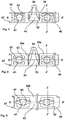
- the space 12 of the hollow profile has, in an advantageous embodiment, a carrier element 30.
- a first embodiment of the carrier element 30 is shown in FIG Fig. 3 shown schematically.
- the carrier element 30 is designed along the axis X-X 'long and advantageously along the axis Z-Z' wider than the piezoelectric measuring element array 20 and in a first space 12 of the hollow section 11 is arranged.
- the carrier element 30 has, in an advantageous embodiment, at least one recess 41, which passes through the carrier element 30 along the axis Y-Y '; wherein the recess 41 retaining clips 42, 43, which retaining clips 42,43 fix a piezoelectric measuring element array 20 with respect to the support member 30.
- the carrier element 30 has at least one holding element 44; wherein a holding member 44 mechanically connects an electronic element 45 to the support member 30; wherein the connection is designed positively or non-positively.
- the electronic element 45 by means of holding elements 44 in the form of flexible hooks with the support member 30 mechanically fixed.
- the electronic element 45 by means of holding elements 44 in the form of screws, screw through holes in the support member 30 and nuts; or in the form of screws and threaded holes in the support member 30, mechanically fixed to the support member 30.
- the electronic element 45 is materially connected to the carrier element 30, for example with a suitable adhesive, wherein no holding elements 44 are necessary.
- the support member 30a is executed in at least two parts, wherein the individual parts of the support member 30a are mechanically connected by the holding members 44 with the electronic element 45.
- the electronic element 45 has a mechanically rigid structure, for example a circuit board.
- the electronic element 45 in this embodiment of the carrier element 30a is a structural component of the carrier element 30a.
- the support member 30b to a predominant part of an electronic element 45, for example, a board, running with at least one recess 41.
- the recess 41 in the electronic element 45 has retaining clips 42, 43, which are materially bonded to the electronic element 45, are positively connected or non-positively connected.
- the retaining clips 42, 43 fix the piezoelectric measuring element arrangement 20 with respect to the carrier element 30b.
- the carrier element 30, 30a, 30b as in FIG. 3, FIG. 4, and FIG. 5 shown, at the respective ends of the support member 30, 30a, 30b with respect to the axis XX 'connecting elements 46, 47; wherein the connecting elements 46, 47 are executed in the embodiment shown in the form of peg-shaped connecting elements 47 and slot-shaped connecting elements 46; wherein the connecting elements 46, 47 connect carrier elements 30, 30 a, 30 b in a form-fitting manner.
- the carrier element 30, 30a, 30b has connecting elements for the non-positive connection of carrier elements 30, 30a, 30b.
- a frictional connection of support elements is effected for example by screw.
- a carrier element 30c is assembled from a plurality of carrier element parts 91, with the connection of a plurality of carrier element parts 91 being effected by form fit, adhesion or material bond.
- a support member 30c shown which consists of two support member parts 91; wherein the carrier element parts 91 by partial connection elements 32, 33 are non-positively or positively connected.
- Part connecting elements 32, 33 are executed in the embodiment shown in the form of pins 32 and slots 33, which are positively connected.
- Part connecting elements 32, 33 can also be designed as a screw connection in a further embodiment.
- carrier 90 The entirety of all in a hollow profile non-positively, positively or materially connected carrier elements 30 is hereinafter referred to as a carrier 90, which in Fig. 10 is shown.
- FIG. 3 to FIG. 5 shown embodiments
- the carrier element 30, 30a, 30b, 30c has, in an advantageous embodiment, guide elements 31 which facilitate a mounting of a carrier, as in FIG Fig. 2 shown.
- a carrier 90 greatly simplifies the process of mounting a WIM sensor 10.
- a WIM sensor 10 will advantageousously, a carrier 90, consisting of connectable carrier elements 30, 30a, 30b, 30c, is premounted with at least one piezoelectric measuring element arrangement 20 20a, 20b and at least one electronic element 45 outside the hollow profile 11.
- the pre-assembly furthermore comprises an electrical connection of all the electronic elements 45 of a WIM sensor 11 by means of connection element 52 and electrical signal conductor 60.
- the electrode film 39 is inserted into a suitable element of the carrier such that the electrode film 39 does not slip laterally relative to the axis Z-Z '.
- a preassembled carrier 90 is drawn into a clamped hollow section 11 together with at least one electrode foil 39; wherein the distance of the pressing surfaces 13, 14 of the hollow section 11 is increased by a lateral force along the axis Z-Z 'on the hollow section 11.
- the guide elements 31 allow easy insertion of the carrier in the hollow profile and ensure precise positioning of the carrier and the electrode film 39 in the hollow profile.
- the support element 30, 30a, 30b, 30c advantageously has a length along the axis XX 'between 100 mm and 1000 mm, in a particularly advantageous embodiment between 100 mm and 300 mm.
- the support member 30, 30a, 30b, 30c therefore, for mounting of Carriers 90 different lengths and thus for different designs with respect to the length of a WIM sensor 10 usable. This reduces the manufacturing costs of a WIM sensor 10.
- Fig. 7 is a part of a fully assembled WIM sensor 10 shown in a schematic sectional view, wherein the support member 30 30a, 30b, 30c is not shown for reasons of clarity.
- the electronic element 45 has in an advantageous embodiment on its underside with respect to the axis YY 'at least one spring contact 48a, 48b; wherein the spring contact 48a, 48b is fixedly connected to the electronic element 45 and presses a spring contact surface 49a, 49b with a defined spring force in the mounted state of the WIM sensor 10 against a surface, for example an electrically conductive region 38a, 38b of the patterned electrode film 39th
- the electronic element 45 has on its upper side with respect to the axis YY 'at least one spring contact 50a, 50b, wherein the spring contact 50a, 50b is fixedly connected to the electronic element 45 and a spring contact surface 51a, 51b with a defined spring force in mounted state of the WIM sensor 10 presses against a surface, such as a pressing surface 13 of the hollow section eleventh
- the spring contacts 48a, 50a establish an electrical connection between the electronic element 45 and the piezoelectric measuring element arrangement 20a by pressing on the spring contact surfaces 49a, 51a.
- a force is applied to the piezoelectric Measuring element 36 a, the electric charges occurring on a second force receiving surface 16 a via the force introduction element 35 a, via the electrically conductive portion 38 a of the electrode film and via the spring member 48 a to the electronic element 45 derived.
- the force introduction element 35a, the electrically conductive region 38a of the electrode foil and the spring element 48a are thus a charge conductor 61a.
- the electrical charges occurring when the force is applied to the piezoelectric measuring element 36a on a first force-receiving surface 15a are dissipated to the electronic element 45 via the force introduction element 34a, via the pressing surface 13 and via the spring element 50a.
- the force introduction element 34a, the pressing surface 13 and the spring element 50a are thus a charge conductor 61a.
- the spring contacts 48b, 50b establish an electrical connection between the electronic element 45 and the piezoelectric measuring element arrangement 20b by the pressing on of the spring contact surfaces 49b, 51b.
- the electrical charges occurring on a second force receiving surface 16b are diverted via the force introduction element 35b, via the electrically conductive region 38b of the electrode foil and via the spring element 48b to the electronic element 45.
- the force introduction element 35b, the electrically conductive region 38b of the electrode foil and the spring element 48b are thus a charge conductor 61b.
- the electrical charges which occur when a force is applied to the piezoelectric measuring element 36b on a first force-receiving surface 15b are transmitted via the force introduction element 34b, via the pressing surface 13 and over the spring element 50b to the electronic element 45 derived.
- the force introduction element 34b, the pressing surface 13 and the spring element 50b are thus a charge conductor 61b.
- the electrically conductive regions 38a and 38b of the electrode foil 39 are electrically insulated from one another by a region of the insulating foil 37 which is not coated electrically. This allows a selective contacting of a piezoelectric measuring element 36a, 36b and thus a separate evaluation of the charge signals of the piezoelectric measuring elements 36a, 36b upon application of force to the respective piezoelectric measuring element 36a, 36b.
- At least two piezoelectric measuring elements 36 are contacted in parallel by means of a region of an electrically conductive layer of an electrode film.
- a piezoelectric measuring element group is understood as meaning at least two piezoelectric measuring element arrangements 20 contacted in parallel.
- a further electrode foil is arranged between the force introduction element 34a, 34b and the pressing surface 13; wherein the electrode foil electrically isolates the pressing surface 13 against the force introduction element 34; wherein an electrically conductive layer is applied on the force introduction element 34a, 34b facing side of the insulating film in a known manner; wherein the force acting on the piezoelectric measuring element 36a, 36b on a first force receiving surface 15a, 15b are discharged via the force introduction element 34a, 34b, via the electrically conductive layer of the further electrode foil and via the spring element 50a, 50b to the electronic element 45.
- the further electrode foil has on at least one side a continuous electrically conductive layer or a structured electrically conductive layer, like the electrode foil 39.
- the carrier element 30, 30a, 30c, 30c each have an electronic element 45 between two piezoelectric measuring element arrangements 20a, 20b, as in FIG 3, 4 and 5 shown.
- On the electronic element 45 is, as in Figure 8
- at least one charge amplifier 21 is arranged, which converts the charge signal 201a, 201b of a piezoelectric measuring element arrangement 20a, 20b or piezoelectric measuring element group into a voltage proportional to the charge signal 201a, 201b or to a current proportional to the charge signal 201a, 201b.
- the electric voltage proportional to the charge signal 201a, 201b or the current proportional to the charge signal 201a, 201b will be referred to below as the charge amplifier signal 202a, 202b.
- at least one A / D converter 22 is arranged, which converts and provides the charge amplifier signal 202a, 202b into a digital charge signal 203.
- Provisioning thus also includes storing the signal on an electronic memory and loading the signal from that memory.
- Provide also includes displaying the signal on a display.
- an A / D converter 22 is not exclusively an electronic component having exactly one signal input and exactly one signal output.
- the person skilled in the art knows an electronic component in which a plurality of signal inputs and a plurality of signal outputs are arranged, which convert a plurality of input signals into a plurality of digital output signals.
- An A / D converter 22 is accordingly to be understood as a pair consisting of a signal input and a signal output of an electronic component in which a plurality of signal inputs and a plurality of signal outputs are arranged.
- a / D converter 22 and charge amplifier 21 be summarized in an electronic component, for example in the form of an application-specific integrated circuit, short ASIC.
- a / D converter 22 and charge amplifier 21 be summarized in an electronic component, for example in the form of an application-specific integrated circuit, short ASIC.
- a / D converter and charge amplifier will be further referred to, though they should be in the form of an ASIC.
- the electronic element 45 has at least one connection element 52 for electrical signal conductors 60, as in FIG Fig. 3 to 5 is shown. In Fig. 8 the electrical signal conductors 60 are shown schematically.
- the connection element 52 allows an electrical connection of at least two electronic elements 45 via electrical signal conductors 60. Electrical signal conductors 60 connect by means of the connecting element 52 electronic elements 45 of a carrier element 30, 30a, 30b 30c or different carrier elements 30, 30a, 30, 30c.
- the WIM sensor 10 has an evaluation element 80 in an advantageous embodiment.
- the evaluation element 80 is arranged in a space 12 of the hollow profile 11.
- Digital charge signals 203 of piezoelectric measuring element arrangements 20, 20a, 20b or piezoelectric measuring element groups are available in the evaluation element 80 for an evaluation.
- At least one microprocessor 82, as well as at least one non-volatile memory element 81, and at least one connection element 52 for an electrical signal conductor 60 are advantageously arranged on the evaluation element 80. Furthermore, an electrical signal conductor 60 connects at least one connection element 52 of an electronic element 45 to an evaluation element 80.
- the use of digital signals requires fewer electrical conductors in an electrical signal conductor 60 than signals are available.
- Digital charge signals 203 of the electronic elements 45 of a WIM sensor 10 are available for evaluation by means of the connection elements 52 and the electrical signal conductors 60 in an evaluation element 80.
- connection element 52 serves for the power supply of an electronic element 45.
- At least one measuring sensor 70 is arranged in a space 12 of the hollow profile 11, which measuring sensor 70 measures a physical size and outputs it as a sensor signal 207.
- An A / D converter 22 converts the sensor signal 207 to a digital sensor signal 204 and provides the digital sensor signal 204 to a connector unit 52.
- the sensor 70 measures one of the following physical quantities: temperature, sound waves, acceleration.
- At least one digital sensor signal 204 is additionally available for evaluation by means of the connection unit 52 and an electrical signal conductor 60 in an evaluation element 80.
- At least one digital charge signal 203 in the evaluation element 80 is calibrated by a calibration function 301.
- the calibration function 301 is a mathematical function with at least one variable.
- the calibration function 301 is stored on the non-volatile memory element 81 and is loaded into the microprocessor 82.
- a plurality of parameters 302 are used, which parameters 302 are characteristic properties of a piezoelectric measuring element 36, 36a, 36b correspond. These characteristic properties are at least the following: A sensitivity and a linearity of a piezoelectric measuring element 36, 36a, 36b.
- a parameter 302 has one or more numerical values, and is uniquely associated with a piezoelectric measuring element 36, 36a, 36b. The linearity and sensitivity were previously determined for the piezoelectric measuring element 36, 36a, 36b.
- the calibration function is a polynomial of finite degree.
- a polynomial sums the multiples of powers of a variable. The multiple is given per power of the variable by a coefficient which is multiplied by the power of the variable.
- the coefficients represent parameter 302.
- the calibration function 301 generates with the digital charge signal 203 of a piezoelectric measuring element 36, 36a, 36b as a variable a calibrated digital charge signal 205, as in FIG Fig. 9 shown schematically.
- the calibrated digital charge signal 205 is linearly related to the wheel load acting on the piezoelectric measuring element 36, 36a, 36b by the choice of the calibration function 301. This serves to increase the measurement accuracy when determining a wheel load acting on a piezoelectric measuring element 36, 36a, 36b of a WIM sensor 10 from a wheel of a vehicle passing over.
- the calibration function 301 and the parameters 302 are preferably determined by a method in which the piezoelectric measuring element 36, 36 a, 36 b in a sequence different sized and defined forces are applied and the digital charge signal 203 is recorded.
- an algorithm first determines, by means of the polynomial interpolation known from numerical mathematics, the interpolation polynomial which, with the digital charge signal 203 as a variable, gives the forces applied in the method.
- This interpolation polynomial is the calibration function 301, which generates the calibrated digital charge signal 205 from the digital charge signal 203 as a variable.
- the sensitivity is given directly by the coefficient of the linear term of the polynomial.
- the linearity is given by the further coefficients of the polynomial.
- the person skilled in the art can choose another mathematical form of the calibration function 301 and select a different method for determining the calibration function.
- the calibration function 301 is provided with a timestamp 208 stored on the non-volatile memory element 81, wherein a time stamp 208 consists of a date and a time and is provided by an algorithm in the microprocessor 82
- the stored calibration function 301 is adapted as part of a new determination of the calibration function 301 by the above-mentioned method; whereby the calibration function 301 previously stored on the non-volatile memory element 81 is replaced.
- the previously existing calibration function 301 is further archived on the non-volatile memory element 81.
- a calibration function 301 is stored for each piezoelectric measuring element 36, 36a, 36b.
- the performance of the WIM sensor 10, aging effects of the piezoelectric measuring element 36, 36a, 36b or aging effects and state of the road surface 2 of the roadway section 1 are determined from a temporal course of the archived calibration functions 301 provided with a time stamp 208.
- the calibration function 301 can be achieved.
- the calibration function 301 generates in the following embodiment with the digital sensor signal 204 of a sensor 70, which detects the temperature of the piezoelectric measuring element 36, 36 a, 36 b, as a variable and with the digital charge signal 203 of a piezoelectric Measuring element 36, 36a, 36b, a calibrated digital charge signal 205.
- the parameters 302 of the calibration function 301 are at least the sensitivity and the linearity and a temperature dependence of the piezoelectric measuring element 36, 36a, 36b, which determines linearity and sensitivity and temperature dependence in advance for the piezoelectric measuring element 36, 36a, 36b are.
- the calibration function 301 generates the calibrated digital charge signal 205 from the digital probe signal 204 and the digital charge signal 203, whereby the calibrated digital charge signal 205 is linearly related to the wheel load acting on the piezoelectric sensing element 36, 36a, 36b and independent of the temperature of the sensor piezoelectric measuring element 36, 36a, 36b.
- a calibration function 301 is assigned to a piezoelectric measuring element 36, 36a, 36b in the microprocessor 82 of the evaluation element of the WIM sensor 10. With the calibration function 301, the calibrated digital charge signal 205 of the piezoelectric measuring element 36, 36a, 36b is generated from the digital charge signal 203 of the piezoelectric measuring element 36, 36a, 36b.
- a total force function 303 is stored in the non-volatile memory element 81.
- the total force function 303 is a mathematical algorithm and is loaded into the microprocessor 82 and applied to all calibrated digital charge signals 205.
- the microprocessor 82 calculates, based on the total force function 303, the total force 206 exerted by a wheel of a vehicle 2 a, 2 b, 2 c, 2 d when crossing over the WIM sensor 10 to the roadway section 1.
Landscapes
- Physics & Mathematics (AREA)
- General Physics & Mathematics (AREA)
- Force Measurement Appropriate To Specific Purposes (AREA)
Priority Applications (1)
| Application Number | Priority Date | Filing Date | Title |
|---|---|---|---|
| PL18211014T PL3499199T3 (pl) | 2017-12-15 | 2018-12-07 | Czujnik vim i sposób wytwarzania czujnika vim |
Applications Claiming Priority (1)
| Application Number | Priority Date | Filing Date | Title |
|---|---|---|---|
| EP17207636 | 2017-12-15 |
Publications (2)
| Publication Number | Publication Date |
|---|---|
| EP3499199A1 true EP3499199A1 (fr) | 2019-06-19 |
| EP3499199B1 EP3499199B1 (fr) | 2021-09-01 |
Family
ID=60673671
Family Applications (1)
| Application Number | Title | Priority Date | Filing Date |
|---|---|---|---|
| EP18211014.8A Active EP3499199B1 (fr) | 2017-12-15 | 2018-12-07 | Capteur wim et procédé de fabrication du capteur wim |
Country Status (7)
| Country | Link |
|---|---|
| US (1) | US10921176B2 (fr) |
| EP (1) | EP3499199B1 (fr) |
| JP (2) | JP6871896B2 (fr) |
| KR (1) | KR102269283B1 (fr) |
| CN (1) | CN109932032B (fr) |
| HU (1) | HUE058966T2 (fr) |
| PL (1) | PL3499199T3 (fr) |
Families Citing this family (5)
| Publication number | Priority date | Publication date | Assignee | Title |
|---|---|---|---|---|
| HUE058966T2 (hu) * | 2017-12-15 | 2022-10-28 | Kistler Holding Ag | WIM-szenzor és módszer a WIM-szenzor gyártására |
| EP3540385B1 (fr) * | 2018-03-16 | 2020-10-28 | Kistler Holding AG | Profilé creux pour capteur wim et capteur wim à profilé creux |
| WO2020120253A1 (fr) * | 2018-12-14 | 2020-06-18 | Kistler Holding Ag | Étalonnage d'un capteur wim |
| US11635323B2 (en) * | 2019-11-07 | 2023-04-25 | GM Global Technology Operations LLC | Vehicle and trailer load determination |
| PL3839447T3 (pl) * | 2019-12-16 | 2023-08-14 | Kistler Holding Ag | Przetwornik siły wim i profil obudowy dla takiego przetwornika siły wim |
Citations (2)
| Publication number | Priority date | Publication date | Assignee | Title |
|---|---|---|---|---|
| US5265481A (en) | 1990-12-19 | 1993-11-30 | Kistler Instrumente Ag | Force sensor systems especially for determining dynamically the axle load, speed, wheelbase and gross weight of vehicles |
| WO2013017768A1 (fr) * | 2011-07-29 | 2013-02-07 | Sterela | Détecteur piézoélectrique extraplat et capteur de passage de véhicules roulants |
Family Cites Families (25)
| Publication number | Priority date | Publication date | Assignee | Title |
|---|---|---|---|---|
| JPS6150013A (ja) | 1984-08-20 | 1986-03-12 | Mitsubishi Heavy Ind Ltd | 車種判別装置 |
| CH683714A5 (de) | 1990-12-19 | 1994-04-29 | Kk Holding Ag | Kraftsensoranordnung, insbesondere zur dynamischen Achslast-, Geschwindigkeits-, Achsabstands- und Gesamtgewichtsbestimmung von Fahrzeugen. |
| JPH06347316A (ja) | 1993-06-11 | 1994-12-22 | Komatsu Ltd | タイヤ輪荷重測定装置 |
| US6019002A (en) * | 1997-12-02 | 2000-02-01 | Setra Systems, Inc. | Pressure transducer having a tensioned diaphragm |
| GB2332277B (en) * | 1997-12-09 | 2000-08-23 | Daewoo Electronics Co Ltd | Method for measuring piezoelectric constant of thin film shaped piezoelectric material |
| JP2002298279A (ja) | 2001-01-26 | 2002-10-11 | Texas Instruments Inc | 状態応答検出システムおよび方法 |
| US6687642B2 (en) | 2001-01-26 | 2004-02-03 | Texas Instruments Incorporated | Condition responsive sense system and method |
| CN101625254B (zh) * | 2009-07-20 | 2013-12-18 | 江西省交通运输技术创新中心 | 压电式动态条形称重板 |
| US20110127090A1 (en) * | 2009-12-02 | 2011-06-02 | Krishna Vijayaraghavan | Weigh-In-Motion (WIM) Sensor |
| CH702963A1 (de) * | 2010-04-01 | 2011-10-14 | Kistler Holding Ag | Verfahren zum kalibrieren von wim-sensoren. |
| DE102010047234B8 (de) * | 2010-10-04 | 2015-12-24 | Schenck Process Gmbh | Wägemodul zur Messung von Radaufstandskräften |
| ES2811552T3 (es) | 2010-10-22 | 2021-03-12 | C Miethke Gmbh&Co Kg | Implante para la medición de la presión intracorporal con transmisión telemétrica del valor de medición |
| CH705675A1 (de) | 2011-10-20 | 2013-04-30 | Kistler Holding Ag | Hohlprofil-Aufnehmer. |
| CH705762A1 (de) | 2011-11-04 | 2013-05-15 | Kistler Holding Ag | Verfahren zum Wiegen eines Fahrzeuges, sowie Messeinrichtung und Messkette hierfür. |
| CH705783A1 (de) | 2011-11-18 | 2013-05-31 | Kistler Holding Ag | WIM Hohlprofil. |
| CH706013A1 (de) * | 2012-01-11 | 2013-07-15 | Kistler Holding Ag | Sensorpaket für WIM Sensor und WIM Sensor. |
| DE102012201333A1 (de) | 2012-01-31 | 2013-08-01 | Deere & Company | Landwirtschaftliche Maschine mit einem System zur selbsttätigen Einstellung eines Bearbeitungsparameters und zugehöriges Verfahren |
| CH706539A1 (de) * | 2012-05-16 | 2013-11-29 | Kistler Holding Ag | Sensormodul eines WIM-Systems und Messverfahren. |
| DE102012014407A1 (de) | 2012-07-19 | 2014-01-23 | Wabco Gmbh | Vorrichtung zur Erfassung und Verarbeitung von Sensormesswerten und/oder zur Steuerung von Aktuatoren |
| US9429463B2 (en) * | 2013-03-04 | 2016-08-30 | International Road Dynamics, Inc. | System and method for measuring moving vehicle information using electrical time domain reflectometry |
| PL3029435T3 (pl) * | 2014-12-01 | 2018-08-31 | Haenni Instruments Ag | Urządzenie z czujnikiem siły do rejestrowania masy pojazdu |
| CN105698908A (zh) * | 2016-03-23 | 2016-06-22 | 华南理工大学 | 一种压电式车辆动态称重传感器 |
| PL3739305T3 (pl) * | 2016-07-26 | 2023-08-21 | Kistler Holding Ag | Czujnik wim z pakietem czujników |
| HUE058966T2 (hu) * | 2017-12-15 | 2022-10-28 | Kistler Holding Ag | WIM-szenzor és módszer a WIM-szenzor gyártására |
| EP3537116B1 (fr) * | 2018-03-05 | 2022-05-11 | Kistler Holding AG | Procédé d'installation d'un capteur de pesage en marche dans une chaussée |
-
2018
- 2018-12-07 HU HUE18211014A patent/HUE058966T2/hu unknown
- 2018-12-07 EP EP18211014.8A patent/EP3499199B1/fr active Active
- 2018-12-07 PL PL18211014T patent/PL3499199T3/pl unknown
- 2018-12-11 US US16/215,950 patent/US10921176B2/en active Active
- 2018-12-11 KR KR1020180158881A patent/KR102269283B1/ko active Active
- 2018-12-14 JP JP2018234263A patent/JP6871896B2/ja active Active
- 2018-12-17 CN CN201811542235.8A patent/CN109932032B/zh active Active
-
2020
- 2020-11-19 JP JP2020192479A patent/JP2021028637A/ja active Pending
Patent Citations (2)
| Publication number | Priority date | Publication date | Assignee | Title |
|---|---|---|---|---|
| US5265481A (en) | 1990-12-19 | 1993-11-30 | Kistler Instrumente Ag | Force sensor systems especially for determining dynamically the axle load, speed, wheelbase and gross weight of vehicles |
| WO2013017768A1 (fr) * | 2011-07-29 | 2013-02-07 | Sterela | Détecteur piézoélectrique extraplat et capteur de passage de véhicules roulants |
Also Published As
| Publication number | Publication date |
|---|---|
| US20190186983A1 (en) | 2019-06-20 |
| EP3499199B1 (fr) | 2021-09-01 |
| KR102269283B1 (ko) | 2021-06-25 |
| JP2021028637A (ja) | 2021-02-25 |
| PL3499199T3 (pl) | 2022-01-03 |
| CN109932032B (zh) | 2021-05-04 |
| US10921176B2 (en) | 2021-02-16 |
| CN109932032A (zh) | 2019-06-25 |
| JP6871896B2 (ja) | 2021-05-19 |
| JP2019109239A (ja) | 2019-07-04 |
| KR20190072431A (ko) | 2019-06-25 |
| HUE058966T2 (hu) | 2022-10-28 |
Similar Documents
| Publication | Publication Date | Title |
|---|---|---|
| EP3499199B1 (fr) | Capteur wim et procédé de fabrication du capteur wim | |
| EP0491655B1 (fr) | Système de capteurs de force, notamment pour détermination dynamique de charge d'essieux, de vitesse, de distance d'essieux et de poids total d'un véhicule | |
| EP1460398B1 (fr) | Capteur de contrainte avec des éléments résistifs et piézoélectriques sensibles aux contraintes | |
| DE3611336C2 (fr) | ||
| EP2029988B1 (fr) | Mesure de la force transversale | |
| DE3417212C2 (de) | Kraftwandler | |
| DE3213319A1 (de) | Einrichtung zum messen von kraft- und momentkomponenten in mehreren richtungen | |
| WO2001023899A1 (fr) | Dispositif de mesure de courant comportant des capteurs differentiels sensibles aux champs magnetiques comprenant au moins deux capteurs de hall | |
| EP3276313A1 (fr) | Capteur wim et boitier | |
| EP3743636B2 (fr) | Dispositif de mesure de l'usure des garnitures de frein pour un frein, frein et ensemble de garnitures de frein | |
| DE2951323A1 (de) | Dehnungsmesseinrichtung | |
| EP3499198A1 (fr) | Capteur wim pourvu de capteurs d'accélération et procédé de mesure de déflexion et de présence au moyen d'un tel capteur | |
| DE102004014708A1 (de) | Halbleitersensor für eine dynamische Grösse | |
| DE19747001C2 (de) | Dehnungsmeßstreifen sowie ein mit diesen Dehnungsmeßstreifen hergestellter mechanisch-elektrischer Wandler | |
| DE102010038851B4 (de) | Elektrische Erfassungsvorrichtung für elektrisch antreibbare Fahrzeuge und Herstellungsverfahren für dieselbe | |
| EP3380851B1 (fr) | Capteur de courant | |
| DE3225215C2 (fr) | ||
| DE102004021862B4 (de) | Stromsenor | |
| DE102007008729A1 (de) | Abtastelement zur Erfassung eines Verschleißwegs eines Bremsbelags | |
| EP0140064B1 (fr) | Transducteur de force ou de pression | |
| DE19529178C2 (de) | Halbleiterbeschleunigungssensor | |
| DE19820005B4 (de) | Flächiger Sensor | |
| DE102010012701A1 (de) | Mikrokraftsensor | |
| DE10114218A1 (de) | Verfahren und Vorrichtung zur Auswertung von Signalen magnetoelastischer Sensoren | |
| DE102014112415A1 (de) | Wägezelle |
Legal Events
| Date | Code | Title | Description |
|---|---|---|---|
| PUAI | Public reference made under article 153(3) epc to a published international application that has entered the european phase |
Free format text: ORIGINAL CODE: 0009012 |
|
| STAA | Information on the status of an ep patent application or granted ep patent |
Free format text: STATUS: THE APPLICATION HAS BEEN PUBLISHED |
|
| AK | Designated contracting states |
Kind code of ref document: A1 Designated state(s): AL AT BE BG CH CY CZ DE DK EE ES FI FR GB GR HR HU IE IS IT LI LT LU LV MC MK MT NL NO PL PT RO RS SE SI SK SM TR |
|
| AX | Request for extension of the european patent |
Extension state: BA ME |
|
| STAA | Information on the status of an ep patent application or granted ep patent |
Free format text: STATUS: REQUEST FOR EXAMINATION WAS MADE |
|
| 17P | Request for examination filed |
Effective date: 20191218 |
|
| RBV | Designated contracting states (corrected) |
Designated state(s): AL AT BE BG CH CY CZ DE DK EE ES FI FR GB GR HR HU IE IS IT LI LT LU LV MC MK MT NL NO PL PT RO RS SE SI SK SM TR |
|
| GRAP | Despatch of communication of intention to grant a patent |
Free format text: ORIGINAL CODE: EPIDOSNIGR1 |
|
| STAA | Information on the status of an ep patent application or granted ep patent |
Free format text: STATUS: GRANT OF PATENT IS INTENDED |
|
| INTG | Intention to grant announced |
Effective date: 20210412 |
|
| GRAS | Grant fee paid |
Free format text: ORIGINAL CODE: EPIDOSNIGR3 |
|
| GRAA | (expected) grant |
Free format text: ORIGINAL CODE: 0009210 |
|
| STAA | Information on the status of an ep patent application or granted ep patent |
Free format text: STATUS: THE PATENT HAS BEEN GRANTED |
|
| AK | Designated contracting states |
Kind code of ref document: B1 Designated state(s): AL AT BE BG CH CY CZ DE DK EE ES FI FR GB GR HR HU IE IS IT LI LT LU LV MC MK MT NL NO PL PT RO RS SE SI SK SM TR |
|
| REG | Reference to a national code |
Ref country code: GB Ref legal event code: FG4D Free format text: NOT ENGLISH |
|
| REG | Reference to a national code |
Ref country code: CH Ref legal event code: EP Ref country code: AT Ref legal event code: REF Ref document number: 1426692 Country of ref document: AT Kind code of ref document: T Effective date: 20210915 |
|
| REG | Reference to a national code |
Ref country code: DE Ref legal event code: R096 Ref document number: 502018006815 Country of ref document: DE |
|
| REG | Reference to a national code |
Ref country code: IE Ref legal event code: FG4D Free format text: LANGUAGE OF EP DOCUMENT: GERMAN |
|
| REG | Reference to a national code |
Ref country code: NL Ref legal event code: FP |
|
| REG | Reference to a national code |
Ref country code: LT Ref legal event code: MG9D |
|
| REG | Reference to a national code |
Ref country code: SK Ref legal event code: T3 Ref document number: E 38653 Country of ref document: SK |
|
| PG25 | Lapsed in a contracting state [announced via postgrant information from national office to epo] |
Ref country code: HR Free format text: LAPSE BECAUSE OF FAILURE TO SUBMIT A TRANSLATION OF THE DESCRIPTION OR TO PAY THE FEE WITHIN THE PRESCRIBED TIME-LIMIT Effective date: 20210901 Ref country code: FI Free format text: LAPSE BECAUSE OF FAILURE TO SUBMIT A TRANSLATION OF THE DESCRIPTION OR TO PAY THE FEE WITHIN THE PRESCRIBED TIME-LIMIT Effective date: 20210901 Ref country code: ES Free format text: LAPSE BECAUSE OF FAILURE TO SUBMIT A TRANSLATION OF THE DESCRIPTION OR TO PAY THE FEE WITHIN THE PRESCRIBED TIME-LIMIT Effective date: 20210901 Ref country code: SE Free format text: LAPSE BECAUSE OF FAILURE TO SUBMIT A TRANSLATION OF THE DESCRIPTION OR TO PAY THE FEE WITHIN THE PRESCRIBED TIME-LIMIT Effective date: 20210901 Ref country code: RS Free format text: LAPSE BECAUSE OF FAILURE TO SUBMIT A TRANSLATION OF THE DESCRIPTION OR TO PAY THE FEE WITHIN THE PRESCRIBED TIME-LIMIT Effective date: 20210901 Ref country code: NO Free format text: LAPSE BECAUSE OF FAILURE TO SUBMIT A TRANSLATION OF THE DESCRIPTION OR TO PAY THE FEE WITHIN THE PRESCRIBED TIME-LIMIT Effective date: 20211201 Ref country code: BG Free format text: LAPSE BECAUSE OF FAILURE TO SUBMIT A TRANSLATION OF THE DESCRIPTION OR TO PAY THE FEE WITHIN THE PRESCRIBED TIME-LIMIT Effective date: 20211201 Ref country code: LT Free format text: LAPSE BECAUSE OF FAILURE TO SUBMIT A TRANSLATION OF THE DESCRIPTION OR TO PAY THE FEE WITHIN THE PRESCRIBED TIME-LIMIT Effective date: 20210901 |
|
| PG25 | Lapsed in a contracting state [announced via postgrant information from national office to epo] |
Ref country code: GR Free format text: LAPSE BECAUSE OF FAILURE TO SUBMIT A TRANSLATION OF THE DESCRIPTION OR TO PAY THE FEE WITHIN THE PRESCRIBED TIME-LIMIT Effective date: 20211202 |
|
| PG25 | Lapsed in a contracting state [announced via postgrant information from national office to epo] |
Ref country code: IS Free format text: LAPSE BECAUSE OF FAILURE TO SUBMIT A TRANSLATION OF THE DESCRIPTION OR TO PAY THE FEE WITHIN THE PRESCRIBED TIME-LIMIT Effective date: 20220101 Ref country code: SM Free format text: LAPSE BECAUSE OF FAILURE TO SUBMIT A TRANSLATION OF THE DESCRIPTION OR TO PAY THE FEE WITHIN THE PRESCRIBED TIME-LIMIT Effective date: 20210901 Ref country code: RO Free format text: LAPSE BECAUSE OF FAILURE TO SUBMIT A TRANSLATION OF THE DESCRIPTION OR TO PAY THE FEE WITHIN THE PRESCRIBED TIME-LIMIT Effective date: 20210901 Ref country code: PT Free format text: LAPSE BECAUSE OF FAILURE TO SUBMIT A TRANSLATION OF THE DESCRIPTION OR TO PAY THE FEE WITHIN THE PRESCRIBED TIME-LIMIT Effective date: 20220103 Ref country code: EE Free format text: LAPSE BECAUSE OF FAILURE TO SUBMIT A TRANSLATION OF THE DESCRIPTION OR TO PAY THE FEE WITHIN THE PRESCRIBED TIME-LIMIT Effective date: 20210901 Ref country code: AL Free format text: LAPSE BECAUSE OF FAILURE TO SUBMIT A TRANSLATION OF THE DESCRIPTION OR TO PAY THE FEE WITHIN THE PRESCRIBED TIME-LIMIT Effective date: 20210901 |
|
| REG | Reference to a national code |
Ref country code: DE Ref legal event code: R097 Ref document number: 502018006815 Country of ref document: DE |
|
| PLBE | No opposition filed within time limit |
Free format text: ORIGINAL CODE: 0009261 |
|
| STAA | Information on the status of an ep patent application or granted ep patent |
Free format text: STATUS: NO OPPOSITION FILED WITHIN TIME LIMIT |
|
| PG25 | Lapsed in a contracting state [announced via postgrant information from national office to epo] |
Ref country code: MC Free format text: LAPSE BECAUSE OF FAILURE TO SUBMIT A TRANSLATION OF THE DESCRIPTION OR TO PAY THE FEE WITHIN THE PRESCRIBED TIME-LIMIT Effective date: 20210901 Ref country code: DK Free format text: LAPSE BECAUSE OF FAILURE TO SUBMIT A TRANSLATION OF THE DESCRIPTION OR TO PAY THE FEE WITHIN THE PRESCRIBED TIME-LIMIT Effective date: 20210901 |
|
| 26N | No opposition filed |
Effective date: 20220602 |
|
| PG25 | Lapsed in a contracting state [announced via postgrant information from national office to epo] |
Ref country code: SI Free format text: LAPSE BECAUSE OF FAILURE TO SUBMIT A TRANSLATION OF THE DESCRIPTION OR TO PAY THE FEE WITHIN THE PRESCRIBED TIME-LIMIT Effective date: 20210901 |
|
| REG | Reference to a national code |
Ref country code: HU Ref legal event code: AG4A Ref document number: E058966 Country of ref document: HU |
|
| PG25 | Lapsed in a contracting state [announced via postgrant information from national office to epo] |
Ref country code: LU Free format text: LAPSE BECAUSE OF NON-PAYMENT OF DUE FEES Effective date: 20211207 Ref country code: IE Free format text: LAPSE BECAUSE OF NON-PAYMENT OF DUE FEES Effective date: 20211207 |
|
| PG25 | Lapsed in a contracting state [announced via postgrant information from national office to epo] |
Ref country code: CY Free format text: LAPSE BECAUSE OF FAILURE TO SUBMIT A TRANSLATION OF THE DESCRIPTION OR TO PAY THE FEE WITHIN THE PRESCRIBED TIME-LIMIT Effective date: 20210901 |
|
| PG25 | Lapsed in a contracting state [announced via postgrant information from national office to epo] |
Ref country code: MK Free format text: LAPSE BECAUSE OF FAILURE TO SUBMIT A TRANSLATION OF THE DESCRIPTION OR TO PAY THE FEE WITHIN THE PRESCRIBED TIME-LIMIT Effective date: 20210901 |
|
| PG25 | Lapsed in a contracting state [announced via postgrant information from national office to epo] |
Ref country code: MT Free format text: LAPSE BECAUSE OF FAILURE TO SUBMIT A TRANSLATION OF THE DESCRIPTION OR TO PAY THE FEE WITHIN THE PRESCRIBED TIME-LIMIT Effective date: 20210901 |
|
| PGFP | Annual fee paid to national office [announced via postgrant information from national office to epo] |
Ref country code: DE Payment date: 20251211 Year of fee payment: 8 |
|
| PGFP | Annual fee paid to national office [announced via postgrant information from national office to epo] |
Ref country code: GB Payment date: 20251219 Year of fee payment: 8 |
|
| PGFP | Annual fee paid to national office [announced via postgrant information from national office to epo] |
Ref country code: AT Payment date: 20251222 Year of fee payment: 8 |
|
| PGFP | Annual fee paid to national office [announced via postgrant information from national office to epo] |
Ref country code: IT Payment date: 20251223 Year of fee payment: 8 |
|
| PGFP | Annual fee paid to national office [announced via postgrant information from national office to epo] |
Ref country code: HU Payment date: 20251223 Year of fee payment: 8 Ref country code: NL Payment date: 20251219 Year of fee payment: 8 Ref country code: FR Payment date: 20251229 Year of fee payment: 8 |
|
| PGFP | Annual fee paid to national office [announced via postgrant information from national office to epo] |
Ref country code: BE Payment date: 20251219 Year of fee payment: 8 Ref country code: TR Payment date: 20251202 Year of fee payment: 8 |
|
| PGFP | Annual fee paid to national office [announced via postgrant information from national office to epo] |
Ref country code: CZ Payment date: 20251202 Year of fee payment: 8 |
|
| PGFP | Annual fee paid to national office [announced via postgrant information from national office to epo] |
Ref country code: LV Payment date: 20251218 Year of fee payment: 8 |
|
| PGFP | Annual fee paid to national office [announced via postgrant information from national office to epo] |
Ref country code: PL Payment date: 20251119 Year of fee payment: 8 |
|
| PGFP | Annual fee paid to national office [announced via postgrant information from national office to epo] |
Ref country code: SK Payment date: 20251203 Year of fee payment: 8 |
|
| REG | Reference to a national code |
Ref country code: CH Ref legal event code: U11 Free format text: ST27 STATUS EVENT CODE: U-0-0-U10-U11 (AS PROVIDED BY THE NATIONAL OFFICE) Effective date: 20260213 |
|
| PGFP | Annual fee paid to national office [announced via postgrant information from national office to epo] |
Ref country code: CH Payment date: 20260213 Year of fee payment: 8 |