EP3499537B1 - Système de fixation à utiliser pour la commutation de pôles à tension moyenne ou élevée - Google Patents
Système de fixation à utiliser pour la commutation de pôles à tension moyenne ou élevée Download PDFInfo
- Publication number
- EP3499537B1 EP3499537B1 EP17207827.1A EP17207827A EP3499537B1 EP 3499537 B1 EP3499537 B1 EP 3499537B1 EP 17207827 A EP17207827 A EP 17207827A EP 3499537 B1 EP3499537 B1 EP 3499537B1
- Authority
- EP
- European Patent Office
- Prior art keywords
- conductive
- fixation system
- screws
- conductive layer
- hole
- Prior art date
- Legal status (The legal status is an assumption and is not a legal conclusion. Google has not performed a legal analysis and makes no representation as to the accuracy of the status listed.)
- Active
Links
Images

Classifications
-
- H—ELECTRICITY
- H01—ELECTRIC ELEMENTS
- H01R—ELECTRICALLY-CONDUCTIVE CONNECTIONS; STRUCTURAL ASSOCIATIONS OF A PLURALITY OF MUTUALLY-INSULATED ELECTRICAL CONNECTING ELEMENTS; COUPLING DEVICES; CURRENT COLLECTORS
- H01R4/00—Electrically-conductive connections between two or more conductive members in direct contact, i.e. touching one another; Means for effecting or maintaining such contact; Electrically-conductive connections having two or more spaced connecting locations for conductors and using contact members penetrating insulation
- H01R4/58—Electrically-conductive connections between two or more conductive members in direct contact, i.e. touching one another; Means for effecting or maintaining such contact; Electrically-conductive connections having two or more spaced connecting locations for conductors and using contact members penetrating insulation characterised by the form or material of the contacting members
- H01R4/64—Connections between or with conductive parts having primarily a non-electric function, e.g. frame, casing, rail
-
- H—ELECTRICITY
- H01—ELECTRIC ELEMENTS
- H01H—ELECTRIC SWITCHES; RELAYS; SELECTORS; EMERGENCY PROTECTIVE DEVICES
- H01H33/00—High-tension or heavy-current switches with arc-extinguishing or arc-preventing means
- H01H33/02—Details
- H01H33/24—Means for preventing discharge to non-current-carrying parts, e.g. using corona ring
-
- H—ELECTRICITY
- H01—ELECTRIC ELEMENTS
- H01H—ELECTRIC SWITCHES; RELAYS; SELECTORS; EMERGENCY PROTECTIVE DEVICES
- H01H33/00—High-tension or heavy-current switches with arc-extinguishing or arc-preventing means
- H01H33/60—Switches wherein the means for extinguishing or preventing the arc do not include separate means for obtaining or increasing flow of arc-extinguishing fluid
- H01H33/66—Vacuum switches
- H01H33/662—Housings or protective screens
- H01H33/66207—Specific housing details, e.g. sealing, soldering or brazing
-
- H—ELECTRICITY
- H01—ELECTRIC ELEMENTS
- H01H—ELECTRIC SWITCHES; RELAYS; SELECTORS; EMERGENCY PROTECTIVE DEVICES
- H01H9/00—Details of switching devices, not covered by groups H01H1/00 - H01H7/00
- H01H9/48—Means for preventing discharge to non-current-carrying parts, e.g. using corona ring
-
- H—ELECTRICITY
- H01—ELECTRIC ELEMENTS
- H01R—ELECTRICALLY-CONDUCTIVE CONNECTIONS; STRUCTURAL ASSOCIATIONS OF A PLURALITY OF MUTUALLY-INSULATED ELECTRICAL CONNECTING ELEMENTS; COUPLING DEVICES; CURRENT COLLECTORS
- H01R4/00—Electrically-conductive connections between two or more conductive members in direct contact, i.e. touching one another; Means for effecting or maintaining such contact; Electrically-conductive connections having two or more spaced connecting locations for conductors and using contact members penetrating insulation
- H01R4/56—Electrically-conductive connections between two or more conductive members in direct contact, i.e. touching one another; Means for effecting or maintaining such contact; Electrically-conductive connections having two or more spaced connecting locations for conductors and using contact members penetrating insulation one conductor screwing into another
-
- H—ELECTRICITY
- H01—ELECTRIC ELEMENTS
- H01R—ELECTRICALLY-CONDUCTIVE CONNECTIONS; STRUCTURAL ASSOCIATIONS OF A PLURALITY OF MUTUALLY-INSULATED ELECTRICAL CONNECTING ELEMENTS; COUPLING DEVICES; CURRENT COLLECTORS
- H01R4/00—Electrically-conductive connections between two or more conductive members in direct contact, i.e. touching one another; Means for effecting or maintaining such contact; Electrically-conductive connections having two or more spaced connecting locations for conductors and using contact members penetrating insulation
- H01R4/28—Clamped connections, spring connections
- H01R4/30—Clamped connections, spring connections utilising a screw or nut clamping member
- H01R4/34—Conductive members located under head of screw
Definitions
- This invention refers to a fixation system for medium and highvoltage switching poles with an insulating housing that is provided with holes, in which screws are screwed into, in order to fix the device on a support, or a further housing.
- Insulating parts in CB or switchgear need to be fixed to other parts. Screws are often used for this purpose. To provide a reliable thread for said screws in insulating parts, dowels are often used. The dowels are permanently fixed to the insulating parts, e.g. by gluing or by integral casting.
- WO2014/102699A1 relates to a pole assembly of a circuit breaker in air insulated switchgear.
- the pole assembly comprises a vacuum interrupter having a fixed contact and a movable contact and at least one terminal.
- the terminal is electrically connected to at least one of the fixed contact or movable contact.
- the at least one terminal is disposed within a hollow connecting piece electrically connected to the at least one of the fixed contact or movable contact.
- US8497446B1 describes an encapsulated vacuum interrupter with grounded end cup and drive rod.
- the double break vacuum interrupter includes a first contact system including an annular stationary contact which is engaged by a primary moving contact with the moving contact drive rod extending through the primary moving contact and through the opening of the annular stationary contact.
- a second contact system includes a secondary moving contact placed on the end of the moving contact rod, which engages and operates a floating contact, which moves along the same axis.
- a mechanical adjustment system is provided for the floating contact.
- a coaxial moving contact drive rod system is provided.
- JPH11331016A describes that a screw hole is formed on the upper surface of a casing composed of a synthetic resin mold. Conductive coating is formed around all the outer peripheral surface of the casing including the screw hole and the conductive coating formed on the outer surface and the conductive coating formed over the screw hole are electrically insulated.
- a connector for mounting and grounding electrical components to an underlying electrically conductive support structure by a mounting screw includes an electrically insulating mounting block which defines at least one mounting hole, and an electrically conductive bus bar which is operatively associated with the mounting block.
- the bus bar is bent to establish a first leg which is sandwiched between the electrically insulating mounting block and the electrically conductive support structure, and a second leg which defines a flat surface which is disposed within the mounting hole of the electrically insulating mounting block.
- At least one bent piece is attached to the second leg and bent so as to bound at least an interior surface portion of the mounting hole defined in the electrically insulating mounting block.
- the first leg of the bus bar makes planar contact with the electrically conductive support structure with the bus bar being positionally fixed in place by the second leg disposed within the mounting hole when the mounting screw is inserted and threaded thereinto.
- Insulating parts in Medium Voltage or High Voltage CB or switchgear are exposed to electrical fields.
- the electrical field is usually not homogeneous.
- areas of high electrical field density can occur especially in the border areas of insulation media and conductors, e.g. where solid insulation parts end and air begins at the surface of a conductive part, also referred to as triple points. Said high electrical field densities can result in partial discharges, limiting the lifetime of the equipment.
- Dowels can have an outer surface with relative large radii and without sharp edges.
- the electrical field density at the transition from the dowel to the insulating part can be relatively low.
- the field strength of the material of the insulating part e.g. duroplast, BMC or thermoplastic material
- the screws are directly inserted into the insulating material.
- the screws that are usually made of electrically conductive material like steel, have relatively sharp edges at their thread. These edges will increase the density of the electrical filed compared to the smooth surface of the dowels.
- the insulating part will provide a hole that will not fully be filled by the inserted screw. Consequently, gas will be present in the region of the high electrical field density. Partial discharges may occur to an extend that is not acceptable for a reliable operation of the CB or switchgear.
- the object of the invention is, to realize a mechanically optimized fixation of the pole part, which is optimized also in its performance of dielectric withstand.
- fixation system as defined in appended claim 1.
- the present invention proposes to make the inner surface of the hole conductive, by deposing a conductive layer.
- the inserted screw will electrically connect to this conductive layer and then to earth potential, or said conductive layer extends to another part, that is directly connected to earth potential, so that the effective surface for the electrical field will be the inner surface of the hole, and no longer the surface of the screw. Further, there will no longer be an electrical field in gas. Triple points are then avoided.
- This conductive varnish can e.g. use silver, coper or graphite particles as conductive component.
- Said activation can be obtained e.g. with a plasma or flame treatment or with a chemical treatment.
- Figure 1 shows the commonly used dowel 2 that is permanently fixed into the insulator 1.
- a screw 3 fixes the insulator to the conductive ground plate 4 that represents earth potential.
- the electrical potential of plate 4 is shown with the thick line 5.
- the other electrical potential shall be represented by the thick line 6.
- the exposition of line 5 towards line 6 is showing a relatively large radius at the top side of the dowel 2.
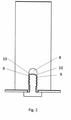
- Figure 2 shows the state of the art when a screw 3 is directly inserted or screwed into a hole 8 of the insulating material 1.
- Line 5 now shows the outline of the screw 3 pointing towards the other electrical potential of line 6. Beside the sharp edges 9 of the end of the thread of the screw, there are additional triple points 10 exposed to the other electrical potential.
- partial discharges are likely to occur first when the overall dimensions are small compared to the applied voltage.
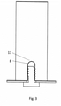
- Figure 3 shows the solution that is proposed in this invention. Due to the added conductivity of the hole 8, the line 5 shows now the relatively large radius of the hole 8. Any triple points in the region around the screw 3 are avoided. There are still sharp edges of the screw, but these are not critical from the electrical point of view, as they are shielded by the ground plate 4 and by the more exposed area 11 of the hole 8.
- the conductive layer at the inside of the hole 8 needs to be electrically connected to the potential of the plate 4, which can be e.g. the ground potential or any other potential.
- This connection can be realised by the conductive screw and / or by pressing the plate 4 to a conductive region at the collar of the hole 8. In the latter case, the proposed principle also works with electrically non-conductive screws.
- the proposed method can be applied to all kinds of casted parts in MV CBs or switchgears, like e.g. bushings or poles.
- the conductive material can be deposed metals layers, or conductive varnishes, or conductive foils.
Landscapes
- Patch Boards (AREA)
- Insulating Bodies (AREA)
Claims (3)
- Système de fixation, comprenant :- un boîtier isolant d'un pôle de commutation moyenne ou haute tension ;- une ou plusieurs vis ; et- un support ou un autre boîtier ;
dans lequel le boîtier isolant comprend un ou plusieurs trous ;
dans lequel une surface interne du trou ou de chacun des trous est rendue conductrice ;
dans lequel la surface interne du trou ou de chacun des trous comprend une couche conductrice ;
dans lequel la couche conductrice est configurée pour se raccorder à un potentiel de terre ; et
dans lequel la ou les vis fixent le boîtier isolant au support ou à l'autre boîtier par le biais du ou des trous. - Système de fixation selon la revendication 1, dans lequel la couche conductrice est configurée pour se raccorder à un potentiel de terre par le biais d'une autre pièce qui est directement raccordée à un potentiel de terre, ou dans lequel la couche conductrice est configurée pour se raccorder à un potentiel de terre par le biais du ou des vis.
- Système de fixation selon la revendication 1, dans lequel la couche conductrice est une couche métallique conductrice, une feuille conductrice ou un vernis conducteur.
Priority Applications (6)
| Application Number | Priority Date | Filing Date | Title |
|---|---|---|---|
| EP17207827.1A EP3499537B1 (fr) | 2017-12-15 | 2017-12-15 | Système de fixation à utiliser pour la commutation de pôles à tension moyenne ou élevée |
| ES17207827T ES2912119T3 (es) | 2017-12-15 | 2017-12-15 | Sistema de fijación en uso para polos de conmutación de media o alta tensión |
| PCT/EP2018/084999 WO2019115785A1 (fr) | 2017-12-15 | 2018-12-14 | Système de fixation servant à des pôles de commutation moyenne ou haute tension |
| RU2020123182A RU2741073C1 (ru) | 2017-12-15 | 2018-12-14 | Система фиксации для полюсов переключателей среднего или высокого напряжения |
| CN201880080383.4A CN111801759A (zh) | 2017-12-15 | 2018-12-14 | 用于中压或高压开关极的固定系统 |
| US16/899,599 US11322864B2 (en) | 2017-12-15 | 2020-06-12 | Fixation system that serves to ground an insulated housing |
Applications Claiming Priority (1)
| Application Number | Priority Date | Filing Date | Title |
|---|---|---|---|
| EP17207827.1A EP3499537B1 (fr) | 2017-12-15 | 2017-12-15 | Système de fixation à utiliser pour la commutation de pôles à tension moyenne ou élevée |
Publications (2)
| Publication Number | Publication Date |
|---|---|
| EP3499537A1 EP3499537A1 (fr) | 2019-06-19 |
| EP3499537B1 true EP3499537B1 (fr) | 2022-02-09 |
Family
ID=60673734
Family Applications (1)
| Application Number | Title | Priority Date | Filing Date |
|---|---|---|---|
| EP17207827.1A Active EP3499537B1 (fr) | 2017-12-15 | 2017-12-15 | Système de fixation à utiliser pour la commutation de pôles à tension moyenne ou élevée |
Country Status (6)
| Country | Link |
|---|---|
| US (1) | US11322864B2 (fr) |
| EP (1) | EP3499537B1 (fr) |
| CN (1) | CN111801759A (fr) |
| ES (1) | ES2912119T3 (fr) |
| RU (1) | RU2741073C1 (fr) |
| WO (1) | WO2019115785A1 (fr) |
Families Citing this family (1)
| Publication number | Priority date | Publication date | Assignee | Title |
|---|---|---|---|---|
| EP4542606A1 (fr) | 2023-10-18 | 2025-04-23 | Abb Schweiz Ag | Installation de commutation basse tension ou installation de commutation moyenne tension ou installation de commutation haute tension |
Citations (1)
| Publication number | Priority date | Publication date | Assignee | Title |
|---|---|---|---|---|
| US5458512A (en) * | 1993-08-18 | 1995-10-17 | Daiichi Denso Buhin Co., Inc. | Mounting and grounding connectors for electrical components |
Family Cites Families (14)
| Publication number | Priority date | Publication date | Assignee | Title |
|---|---|---|---|---|
| JPH08130387A (ja) * | 1994-11-02 | 1996-05-21 | Fujitsu Ltd | 回路ユニットのシールド構造 |
| FR2748352B1 (fr) * | 1996-05-03 | 1998-07-17 | Arnould App Electr | Socle de branchement pour reseau de transmission, en particulier pour reseau telephonique ou informatique |
| JP3570891B2 (ja) * | 1998-05-18 | 2004-09-29 | アルプス電気株式会社 | 送受信ユニット |
| CN201122498Y (zh) * | 2007-10-08 | 2008-09-24 | 特变电工衡阳变压器有限公司 | 一种新型的铁心拉带锁紧装置 |
| US8231080B2 (en) * | 2009-02-26 | 2012-07-31 | The Boeing Company | Distributing power in systems having a composite structure |
| CN201858224U (zh) * | 2010-10-15 | 2011-06-08 | 中国西电电气股份有限公司 | 一种金属部件间的连接结构 |
| US8471166B1 (en) * | 2011-01-24 | 2013-06-25 | Michael David Glaser | Double break vacuum interrupter |
| US8497446B1 (en) * | 2011-01-24 | 2013-07-30 | Michael David Glaser | Encapsulated vacuum interrupter with grounded end cup and drive rod |
| WO2014102699A1 (fr) * | 2012-12-24 | 2014-07-03 | Abb Technology Ltd | Ensemble pôle d'un disjoncteur dans un appareillage de commutation isolé par air |
| CN203774066U (zh) * | 2014-04-17 | 2014-08-13 | 浙江银马电气有限公司 | 干式变压器 |
| CN204088021U (zh) * | 2014-08-20 | 2015-01-07 | 黄有茂 | 一种防止局部放电的干式变压器 |
| RU154884U1 (ru) * | 2014-12-03 | 2015-09-10 | Закрытое акционерное общество "Производственное объединение Электротехник" | Выключатель путевой |
| RU155329U1 (ru) * | 2015-01-30 | 2015-10-10 | Закрытое акционерное общество "Производственное объединение Электротехник" | Контактный блок выключателя путевого |
| CN106159395B (zh) * | 2015-04-16 | 2021-01-08 | 深圳市大富科技股份有限公司 | 腔体滤波器、双工器和射频拉远设备 |
-
2017
- 2017-12-15 EP EP17207827.1A patent/EP3499537B1/fr active Active
- 2017-12-15 ES ES17207827T patent/ES2912119T3/es active Active
-
2018
- 2018-12-14 WO PCT/EP2018/084999 patent/WO2019115785A1/fr not_active Ceased
- 2018-12-14 RU RU2020123182A patent/RU2741073C1/ru active
- 2018-12-14 CN CN201880080383.4A patent/CN111801759A/zh active Pending
-
2020
- 2020-06-12 US US16/899,599 patent/US11322864B2/en active Active
Patent Citations (1)
| Publication number | Priority date | Publication date | Assignee | Title |
|---|---|---|---|---|
| US5458512A (en) * | 1993-08-18 | 1995-10-17 | Daiichi Denso Buhin Co., Inc. | Mounting and grounding connectors for electrical components |
Also Published As
| Publication number | Publication date |
|---|---|
| RU2741073C1 (ru) | 2021-01-22 |
| ES2912119T3 (es) | 2022-05-24 |
| CN111801759A (zh) | 2020-10-20 |
| US20200313317A1 (en) | 2020-10-01 |
| EP3499537A1 (fr) | 2019-06-19 |
| WO2019115785A1 (fr) | 2019-06-20 |
| US11322864B2 (en) | 2022-05-03 |
Similar Documents
| Publication | Publication Date | Title |
|---|---|---|
| KR101693454B1 (ko) | 모선 접속 장치 및 그것을 이용한 스위치 기어 | |
| US20150244156A1 (en) | Integrated compact bushing structure combining the functionality of primary contact with a current transformer primary conductor and a post insulator | |
| US11901709B2 (en) | Gas-insulated switchgear | |
| EP2819143A1 (fr) | Disjoncteur à vide de type réservoir | |
| JP6563160B1 (ja) | 母線接続装置 | |
| US11322864B2 (en) | Fixation system that serves to ground an insulated housing | |
| JP2009022115A (ja) | 固体絶縁スイッチギヤおよびその試験方法 | |
| CN102388514A (zh) | 连接气体绝缘开关柜与空气绝缘开关柜的套管 | |
| WO2004114491A3 (fr) | Disjoncteur avec isolateurs de traversee colles | |
| WO2022069971A1 (fr) | Embout isolant à capteur | |
| KR20020032345A (ko) | 가스 절연 개폐장치 | |
| CN1461507A (zh) | 母线连接装置 | |
| CA2877412A1 (fr) | Isolant en forme de disque pour appareillage de connexion a isolation gazeuse | |
| JP4190320B2 (ja) | スイッチギヤ | |
| TWI378475B (fr) | ||
| JP2716210B2 (ja) | スイッチ | |
| WO2013125554A1 (fr) | Appareillage de commutation isolé au gaz et barre omnibus isolée au gaz | |
| CN111029207B (zh) | 带有用于衬套的布置的开关设备 | |
| KR100584877B1 (ko) | 가스개폐기용 부싱 | |
| CN114391104A (zh) | 用于测量功率开关装置中的导体处的电压电势的测量装置和相应的功率开关装置 | |
| US6987438B2 (en) | Bushing-type transformer for a switch gear unit | |
| US20060225913A1 (en) | Cast-resin insulator having reduced leakage path formation | |
| EP2117014B1 (fr) | Contact de traversée haute tension, traversée haute tension comprenant ledit contact et dispositif haute tension comprenant une traversée dotée dudit contact | |
| JPH0749690Y2 (ja) | 碍子,碍管の破損防止装置 | |
| EP4542606A1 (fr) | Installation de commutation basse tension ou installation de commutation moyenne tension ou installation de commutation haute tension |
Legal Events
| Date | Code | Title | Description |
|---|---|---|---|
| PUAI | Public reference made under article 153(3) epc to a published international application that has entered the european phase |
Free format text: ORIGINAL CODE: 0009012 |
|
| STAA | Information on the status of an ep patent application or granted ep patent |
Free format text: STATUS: THE APPLICATION HAS BEEN PUBLISHED |
|
| AK | Designated contracting states |
Kind code of ref document: A1 Designated state(s): AL AT BE BG CH CY CZ DE DK EE ES FI FR GB GR HR HU IE IS IT LI LT LU LV MC MK MT NL NO PL PT RO RS SE SI SK SM TR |
|
| AX | Request for extension of the european patent |
Extension state: BA ME |
|
| STAA | Information on the status of an ep patent application or granted ep patent |
Free format text: STATUS: REQUEST FOR EXAMINATION WAS MADE |
|
| 17P | Request for examination filed |
Effective date: 20191209 |
|
| RBV | Designated contracting states (corrected) |
Designated state(s): AL AT BE BG CH CY CZ DE DK EE ES FI FR GB GR HR HU IE IS IT LI LT LU LV MC MK MT NL NO PL PT RO RS SE SI SK SM TR |
|
| STAA | Information on the status of an ep patent application or granted ep patent |
Free format text: STATUS: EXAMINATION IS IN PROGRESS |
|
| 17Q | First examination report despatched |
Effective date: 20210303 |
|
| GRAP | Despatch of communication of intention to grant a patent |
Free format text: ORIGINAL CODE: EPIDOSNIGR1 |
|
| STAA | Information on the status of an ep patent application or granted ep patent |
Free format text: STATUS: GRANT OF PATENT IS INTENDED |
|
| GRAJ | Information related to disapproval of communication of intention to grant by the applicant or resumption of examination proceedings by the epo deleted |
Free format text: ORIGINAL CODE: EPIDOSDIGR1 |
|
| STAA | Information on the status of an ep patent application or granted ep patent |
Free format text: STATUS: EXAMINATION IS IN PROGRESS |
|
| INTG | Intention to grant announced |
Effective date: 20210803 |
|
| GRAP | Despatch of communication of intention to grant a patent |
Free format text: ORIGINAL CODE: EPIDOSNIGR1 |
|
| STAA | Information on the status of an ep patent application or granted ep patent |
Free format text: STATUS: GRANT OF PATENT IS INTENDED |
|
| INTC | Intention to grant announced (deleted) | ||
| INTG | Intention to grant announced |
Effective date: 20210927 |
|
| GRAS | Grant fee paid |
Free format text: ORIGINAL CODE: EPIDOSNIGR3 |
|
| GRAA | (expected) grant |
Free format text: ORIGINAL CODE: 0009210 |
|
| STAA | Information on the status of an ep patent application or granted ep patent |
Free format text: STATUS: THE PATENT HAS BEEN GRANTED |
|
| AK | Designated contracting states |
Kind code of ref document: B1 Designated state(s): AL AT BE BG CH CY CZ DE DK EE ES FI FR GB GR HR HU IE IS IT LI LT LU LV MC MK MT NL NO PL PT RO RS SE SI SK SM TR |
|
| RAP3 | Party data changed (applicant data changed or rights of an application transferred) |
Owner name: ABB SCHWEIZ AG |
|
| REG | Reference to a national code |
Ref country code: GB Ref legal event code: FG4D |
|
| REG | Reference to a national code |
Ref country code: CH Ref legal event code: EP Ref country code: AT Ref legal event code: REF Ref document number: 1468018 Country of ref document: AT Kind code of ref document: T Effective date: 20220215 |
|
| REG | Reference to a national code |
Ref country code: IE Ref legal event code: FG4D |
|
| REG | Reference to a national code |
Ref country code: DE Ref legal event code: R096 Ref document number: 602017053121 Country of ref document: DE |
|
| REG | Reference to a national code |
Ref country code: ES Ref legal event code: FG2A Ref document number: 2912119 Country of ref document: ES Kind code of ref document: T3 Effective date: 20220524 |
|
| REG | Reference to a national code |
Ref country code: LT Ref legal event code: MG9D |
|
| REG | Reference to a national code |
Ref country code: NL Ref legal event code: MP Effective date: 20220209 |
|
| REG | Reference to a national code |
Ref country code: AT Ref legal event code: MK05 Ref document number: 1468018 Country of ref document: AT Kind code of ref document: T Effective date: 20220209 |
|
| PG25 | Lapsed in a contracting state [announced via postgrant information from national office to epo] |
Ref country code: SE Free format text: LAPSE BECAUSE OF FAILURE TO SUBMIT A TRANSLATION OF THE DESCRIPTION OR TO PAY THE FEE WITHIN THE PRESCRIBED TIME-LIMIT Effective date: 20220209 Ref country code: RS Free format text: LAPSE BECAUSE OF FAILURE TO SUBMIT A TRANSLATION OF THE DESCRIPTION OR TO PAY THE FEE WITHIN THE PRESCRIBED TIME-LIMIT Effective date: 20220209 Ref country code: PT Free format text: LAPSE BECAUSE OF FAILURE TO SUBMIT A TRANSLATION OF THE DESCRIPTION OR TO PAY THE FEE WITHIN THE PRESCRIBED TIME-LIMIT Effective date: 20220609 Ref country code: NO Free format text: LAPSE BECAUSE OF FAILURE TO SUBMIT A TRANSLATION OF THE DESCRIPTION OR TO PAY THE FEE WITHIN THE PRESCRIBED TIME-LIMIT Effective date: 20220509 Ref country code: NL Free format text: LAPSE BECAUSE OF FAILURE TO SUBMIT A TRANSLATION OF THE DESCRIPTION OR TO PAY THE FEE WITHIN THE PRESCRIBED TIME-LIMIT Effective date: 20220209 Ref country code: LT Free format text: LAPSE BECAUSE OF FAILURE TO SUBMIT A TRANSLATION OF THE DESCRIPTION OR TO PAY THE FEE WITHIN THE PRESCRIBED TIME-LIMIT Effective date: 20220209 Ref country code: HR Free format text: LAPSE BECAUSE OF FAILURE TO SUBMIT A TRANSLATION OF THE DESCRIPTION OR TO PAY THE FEE WITHIN THE PRESCRIBED TIME-LIMIT Effective date: 20220209 Ref country code: BG Free format text: LAPSE BECAUSE OF FAILURE TO SUBMIT A TRANSLATION OF THE DESCRIPTION OR TO PAY THE FEE WITHIN THE PRESCRIBED TIME-LIMIT Effective date: 20220509 |
|
| PG25 | Lapsed in a contracting state [announced via postgrant information from national office to epo] |
Ref country code: PL Free format text: LAPSE BECAUSE OF FAILURE TO SUBMIT A TRANSLATION OF THE DESCRIPTION OR TO PAY THE FEE WITHIN THE PRESCRIBED TIME-LIMIT Effective date: 20220209 Ref country code: LV Free format text: LAPSE BECAUSE OF FAILURE TO SUBMIT A TRANSLATION OF THE DESCRIPTION OR TO PAY THE FEE WITHIN THE PRESCRIBED TIME-LIMIT Effective date: 20220209 Ref country code: GR Free format text: LAPSE BECAUSE OF FAILURE TO SUBMIT A TRANSLATION OF THE DESCRIPTION OR TO PAY THE FEE WITHIN THE PRESCRIBED TIME-LIMIT Effective date: 20220510 Ref country code: FI Free format text: LAPSE BECAUSE OF FAILURE TO SUBMIT A TRANSLATION OF THE DESCRIPTION OR TO PAY THE FEE WITHIN THE PRESCRIBED TIME-LIMIT Effective date: 20220209 Ref country code: AT Free format text: LAPSE BECAUSE OF FAILURE TO SUBMIT A TRANSLATION OF THE DESCRIPTION OR TO PAY THE FEE WITHIN THE PRESCRIBED TIME-LIMIT Effective date: 20220209 |
|
| PG25 | Lapsed in a contracting state [announced via postgrant information from national office to epo] |
Ref country code: IS Free format text: LAPSE BECAUSE OF FAILURE TO SUBMIT A TRANSLATION OF THE DESCRIPTION OR TO PAY THE FEE WITHIN THE PRESCRIBED TIME-LIMIT Effective date: 20220609 |
|
| PG25 | Lapsed in a contracting state [announced via postgrant information from national office to epo] |
Ref country code: SM Free format text: LAPSE BECAUSE OF FAILURE TO SUBMIT A TRANSLATION OF THE DESCRIPTION OR TO PAY THE FEE WITHIN THE PRESCRIBED TIME-LIMIT Effective date: 20220209 Ref country code: SK Free format text: LAPSE BECAUSE OF FAILURE TO SUBMIT A TRANSLATION OF THE DESCRIPTION OR TO PAY THE FEE WITHIN THE PRESCRIBED TIME-LIMIT Effective date: 20220209 Ref country code: RO Free format text: LAPSE BECAUSE OF FAILURE TO SUBMIT A TRANSLATION OF THE DESCRIPTION OR TO PAY THE FEE WITHIN THE PRESCRIBED TIME-LIMIT Effective date: 20220209 Ref country code: EE Free format text: LAPSE BECAUSE OF FAILURE TO SUBMIT A TRANSLATION OF THE DESCRIPTION OR TO PAY THE FEE WITHIN THE PRESCRIBED TIME-LIMIT Effective date: 20220209 Ref country code: DK Free format text: LAPSE BECAUSE OF FAILURE TO SUBMIT A TRANSLATION OF THE DESCRIPTION OR TO PAY THE FEE WITHIN THE PRESCRIBED TIME-LIMIT Effective date: 20220209 Ref country code: CZ Free format text: LAPSE BECAUSE OF FAILURE TO SUBMIT A TRANSLATION OF THE DESCRIPTION OR TO PAY THE FEE WITHIN THE PRESCRIBED TIME-LIMIT Effective date: 20220209 |
|
| REG | Reference to a national code |
Ref country code: DE Ref legal event code: R097 Ref document number: 602017053121 Country of ref document: DE |
|
| PG25 | Lapsed in a contracting state [announced via postgrant information from national office to epo] |
Ref country code: AL Free format text: LAPSE BECAUSE OF FAILURE TO SUBMIT A TRANSLATION OF THE DESCRIPTION OR TO PAY THE FEE WITHIN THE PRESCRIBED TIME-LIMIT Effective date: 20220209 |
|
| PLBE | No opposition filed within time limit |
Free format text: ORIGINAL CODE: 0009261 |
|
| STAA | Information on the status of an ep patent application or granted ep patent |
Free format text: STATUS: NO OPPOSITION FILED WITHIN TIME LIMIT |
|
| 26N | No opposition filed |
Effective date: 20221110 |
|
| PG25 | Lapsed in a contracting state [announced via postgrant information from national office to epo] |
Ref country code: SI Free format text: LAPSE BECAUSE OF FAILURE TO SUBMIT A TRANSLATION OF THE DESCRIPTION OR TO PAY THE FEE WITHIN THE PRESCRIBED TIME-LIMIT Effective date: 20220209 |
|
| REG | Reference to a national code |
Ref country code: CH Ref legal event code: PL |
|
| GBPC | Gb: european patent ceased through non-payment of renewal fee |
Effective date: 20221215 |
|
| REG | Reference to a national code |
Ref country code: BE Ref legal event code: MM Effective date: 20221231 |
|
| PG25 | Lapsed in a contracting state [announced via postgrant information from national office to epo] |
Ref country code: LU Free format text: LAPSE BECAUSE OF NON-PAYMENT OF DUE FEES Effective date: 20221215 |
|
| PG25 | Lapsed in a contracting state [announced via postgrant information from national office to epo] |
Ref country code: LI Free format text: LAPSE BECAUSE OF NON-PAYMENT OF DUE FEES Effective date: 20221231 Ref country code: IE Free format text: LAPSE BECAUSE OF NON-PAYMENT OF DUE FEES Effective date: 20221215 Ref country code: GB Free format text: LAPSE BECAUSE OF NON-PAYMENT OF DUE FEES Effective date: 20221215 Ref country code: CH Free format text: LAPSE BECAUSE OF NON-PAYMENT OF DUE FEES Effective date: 20221231 |
|
| PG25 | Lapsed in a contracting state [announced via postgrant information from national office to epo] |
Ref country code: BE Free format text: LAPSE BECAUSE OF NON-PAYMENT OF DUE FEES Effective date: 20221231 |
|
| PG25 | Lapsed in a contracting state [announced via postgrant information from national office to epo] |
Ref country code: HU Free format text: LAPSE BECAUSE OF FAILURE TO SUBMIT A TRANSLATION OF THE DESCRIPTION OR TO PAY THE FEE WITHIN THE PRESCRIBED TIME-LIMIT; INVALID AB INITIO Effective date: 20171215 |
|
| PG25 | Lapsed in a contracting state [announced via postgrant information from national office to epo] |
Ref country code: CY Free format text: LAPSE BECAUSE OF FAILURE TO SUBMIT A TRANSLATION OF THE DESCRIPTION OR TO PAY THE FEE WITHIN THE PRESCRIBED TIME-LIMIT Effective date: 20220209 |
|
| PG25 | Lapsed in a contracting state [announced via postgrant information from national office to epo] |
Ref country code: MK Free format text: LAPSE BECAUSE OF FAILURE TO SUBMIT A TRANSLATION OF THE DESCRIPTION OR TO PAY THE FEE WITHIN THE PRESCRIBED TIME-LIMIT Effective date: 20220209 |
|
| PG25 | Lapsed in a contracting state [announced via postgrant information from national office to epo] |
Ref country code: MC Free format text: LAPSE BECAUSE OF FAILURE TO SUBMIT A TRANSLATION OF THE DESCRIPTION OR TO PAY THE FEE WITHIN THE PRESCRIBED TIME-LIMIT Effective date: 20220209 |
|
| PG25 | Lapsed in a contracting state [announced via postgrant information from national office to epo] |
Ref country code: MC Free format text: LAPSE BECAUSE OF FAILURE TO SUBMIT A TRANSLATION OF THE DESCRIPTION OR TO PAY THE FEE WITHIN THE PRESCRIBED TIME-LIMIT Effective date: 20220209 |
|
| PG25 | Lapsed in a contracting state [announced via postgrant information from national office to epo] |
Ref country code: MT Free format text: LAPSE BECAUSE OF FAILURE TO SUBMIT A TRANSLATION OF THE DESCRIPTION OR TO PAY THE FEE WITHIN THE PRESCRIBED TIME-LIMIT Effective date: 20220209 |
|
| PG25 | Lapsed in a contracting state [announced via postgrant information from national office to epo] |
Ref country code: TR Free format text: LAPSE BECAUSE OF FAILURE TO SUBMIT A TRANSLATION OF THE DESCRIPTION OR TO PAY THE FEE WITHIN THE PRESCRIBED TIME-LIMIT Effective date: 20220209 |
|
| PGFP | Annual fee paid to national office [announced via postgrant information from national office to epo] |
Ref country code: DE Payment date: 20251211 Year of fee payment: 9 |
|
| PGFP | Annual fee paid to national office [announced via postgrant information from national office to epo] |
Ref country code: IT Payment date: 20251223 Year of fee payment: 9 |
|
| PGFP | Annual fee paid to national office [announced via postgrant information from national office to epo] |
Ref country code: FR Payment date: 20251229 Year of fee payment: 9 |
|
| PGFP | Annual fee paid to national office [announced via postgrant information from national office to epo] |
Ref country code: ES Payment date: 20260130 Year of fee payment: 9 |