EP3499604A1 - Stromversorgungsvorrichtung - Google Patents
Stromversorgungsvorrichtung Download PDFInfo
- Publication number
- EP3499604A1 EP3499604A1 EP17839012.6A EP17839012A EP3499604A1 EP 3499604 A1 EP3499604 A1 EP 3499604A1 EP 17839012 A EP17839012 A EP 17839012A EP 3499604 A1 EP3499604 A1 EP 3499604A1
- Authority
- EP
- European Patent Office
- Prior art keywords
- container
- power
- electricity storage
- battery
- power supply
- Prior art date
- Legal status (The legal status is an assumption and is not a legal conclusion. Google has not performed a legal analysis and makes no representation as to the accuracy of the status listed.)
- Withdrawn
Links
Images




Classifications
-
- H—ELECTRICITY
- H02—GENERATION; CONVERSION OR DISTRIBUTION OF ELECTRIC POWER
- H02J—ELECTRIC POWER NETWORKS; CIRCUIT ARRANGEMENTS OR SYSTEMS FOR SUPPLYING OR DISTRIBUTING ELECTRIC POWER; SYSTEMS FOR STORING ELECTRIC ENERGY
- H02J3/00—Circuit arrangements for AC mains or AC distribution networks
- H02J3/28—Arrangements for balancing of the load in networks by storage of energy
- H02J3/32—Arrangements for balancing of the load in networks by storage of energy using batteries or super capacitors with converting means
-
- H—ELECTRICITY
- H01—ELECTRIC ELEMENTS
- H01M—PROCESSES OR MEANS, e.g. BATTERIES, FOR THE DIRECT CONVERSION OF CHEMICAL ENERGY INTO ELECTRICAL ENERGY
- H01M10/00—Secondary cells; Manufacture thereof
- H01M10/42—Methods or arrangements for servicing or maintenance of secondary cells or secondary half-cells
- H01M10/44—Methods for charging or discharging
- H01M10/441—Methods for charging or discharging for several batteries or cells simultaneously or sequentially
-
- H—ELECTRICITY
- H01—ELECTRIC ELEMENTS
- H01M—PROCESSES OR MEANS, e.g. BATTERIES, FOR THE DIRECT CONVERSION OF CHEMICAL ENERGY INTO ELECTRICAL ENERGY
- H01M10/00—Secondary cells; Manufacture thereof
- H01M10/05—Accumulators with non-aqueous electrolyte
- H01M10/052—Li-accumulators
- H01M10/0525—Rocking-chair batteries, i.e. batteries with lithium insertion or intercalation in both electrodes; Lithium-ion batteries
-
- H—ELECTRICITY
- H01—ELECTRIC ELEMENTS
- H01M—PROCESSES OR MEANS, e.g. BATTERIES, FOR THE DIRECT CONVERSION OF CHEMICAL ENERGY INTO ELECTRICAL ENERGY
- H01M10/00—Secondary cells; Manufacture thereof
- H01M10/42—Methods or arrangements for servicing or maintenance of secondary cells or secondary half-cells
- H01M10/44—Methods for charging or discharging
-
- H—ELECTRICITY
- H01—ELECTRIC ELEMENTS
- H01M—PROCESSES OR MEANS, e.g. BATTERIES, FOR THE DIRECT CONVERSION OF CHEMICAL ENERGY INTO ELECTRICAL ENERGY
- H01M50/00—Constructional details or processes of manufacture of the non-active parts of electrochemical cells other than fuel cells, e.g. hybrid cells
- H01M50/20—Mountings; Secondary casings or frames; Racks, modules or packs; Suspension devices; Shock absorbers; Transport or carrying devices; Holders
- H01M50/204—Racks, modules or packs for multiple batteries or multiple cells
-
- H—ELECTRICITY
- H01—ELECTRIC ELEMENTS
- H01M—PROCESSES OR MEANS, e.g. BATTERIES, FOR THE DIRECT CONVERSION OF CHEMICAL ENERGY INTO ELECTRICAL ENERGY
- H01M50/00—Constructional details or processes of manufacture of the non-active parts of electrochemical cells other than fuel cells, e.g. hybrid cells
- H01M50/20—Mountings; Secondary casings or frames; Racks, modules or packs; Suspension devices; Shock absorbers; Transport or carrying devices; Holders
- H01M50/218—Mountings; Secondary casings or frames; Racks, modules or packs; Suspension devices; Shock absorbers; Transport or carrying devices; Holders characterised by the material
- H01M50/22—Mountings; Secondary casings or frames; Racks, modules or packs; Suspension devices; Shock absorbers; Transport or carrying devices; Holders characterised by the material of the casings or racks
- H01M50/222—Inorganic material
- H01M50/224—Metals
-
- H—ELECTRICITY
- H01—ELECTRIC ELEMENTS
- H01M—PROCESSES OR MEANS, e.g. BATTERIES, FOR THE DIRECT CONVERSION OF CHEMICAL ENERGY INTO ELECTRICAL ENERGY
- H01M50/00—Constructional details or processes of manufacture of the non-active parts of electrochemical cells other than fuel cells, e.g. hybrid cells
- H01M50/20—Mountings; Secondary casings or frames; Racks, modules or packs; Suspension devices; Shock absorbers; Transport or carrying devices; Holders
- H01M50/298—Mountings; Secondary casings or frames; Racks, modules or packs; Suspension devices; Shock absorbers; Transport or carrying devices; Holders characterised by the wiring of battery packs
-
- H—ELECTRICITY
- H02—GENERATION; CONVERSION OR DISTRIBUTION OF ELECTRIC POWER
- H02J—ELECTRIC POWER NETWORKS; CIRCUIT ARRANGEMENTS OR SYSTEMS FOR SUPPLYING OR DISTRIBUTING ELECTRIC POWER; SYSTEMS FOR STORING ELECTRIC ENERGY
- H02J3/00—Circuit arrangements for AC mains or AC distribution networks
- H02J3/38—Arrangements for feeding a single network from two or more generators or sources in parallel; Arrangements for feeding already energised networks from additional generators or sources in parallel
-
- H—ELECTRICITY
- H02—GENERATION; CONVERSION OR DISTRIBUTION OF ELECTRIC POWER
- H02J—ELECTRIC POWER NETWORKS; CIRCUIT ARRANGEMENTS OR SYSTEMS FOR SUPPLYING OR DISTRIBUTING ELECTRIC POWER; SYSTEMS FOR STORING ELECTRIC ENERGY
- H02J9/00—Circuit arrangements for emergency or stand-by power supply, e.g. for emergency lighting
- H02J9/04—Circuit arrangements for emergency or stand-by power supply, e.g. for emergency lighting in which the distribution system is disconnected from the normal source and connected to a standby source
- H02J9/06—Circuit arrangements for emergency or stand-by power supply, e.g. for emergency lighting in which the distribution system is disconnected from the normal source and connected to a standby source with automatic change-over, e.g. UPS systems
- H02J9/061—Circuit arrangements for emergency or stand-by power supply, e.g. for emergency lighting in which the distribution system is disconnected from the normal source and connected to a standby source with automatic change-over, e.g. UPS systems for DC powered loads
-
- H—ELECTRICITY
- H01—ELECTRIC ELEMENTS
- H01M—PROCESSES OR MEANS, e.g. BATTERIES, FOR THE DIRECT CONVERSION OF CHEMICAL ENERGY INTO ELECTRICAL ENERGY
- H01M2220/00—Batteries for particular applications
- H01M2220/10—Batteries in stationary systems, e.g. emergency power source in plant
-
- H—ELECTRICITY
- H01—ELECTRIC ELEMENTS
- H01M—PROCESSES OR MEANS, e.g. BATTERIES, FOR THE DIRECT CONVERSION OF CHEMICAL ENERGY INTO ELECTRICAL ENERGY
- H01M50/00—Constructional details or processes of manufacture of the non-active parts of electrochemical cells other than fuel cells, e.g. hybrid cells
- H01M50/20—Mountings; Secondary casings or frames; Racks, modules or packs; Suspension devices; Shock absorbers; Transport or carrying devices; Holders
- H01M50/251—Mountings; Secondary casings or frames; Racks, modules or packs; Suspension devices; Shock absorbers; Transport or carrying devices; Holders specially adapted for stationary devices, e.g. power plant buffering or backup power supplies
-
- Y—GENERAL TAGGING OF NEW TECHNOLOGICAL DEVELOPMENTS; GENERAL TAGGING OF CROSS-SECTIONAL TECHNOLOGIES SPANNING OVER SEVERAL SECTIONS OF THE IPC; TECHNICAL SUBJECTS COVERED BY FORMER USPC CROSS-REFERENCE ART COLLECTIONS [XRACs] AND DIGESTS
- Y02—TECHNOLOGIES OR APPLICATIONS FOR MITIGATION OR ADAPTATION AGAINST CLIMATE CHANGE
- Y02E—REDUCTION OF GREENHOUSE GAS [GHG] EMISSIONS, RELATED TO ENERGY GENERATION, TRANSMISSION OR DISTRIBUTION
- Y02E60/00—Enabling technologies; Technologies with a potential or indirect contribution to GHG emissions mitigation
- Y02E60/10—Energy storage using batteries
Definitions
- the present technology relates to a power supply apparatus using, for example, lithium ion secondary batteries.
- an electricity storage system as a power supply apparatus by using a large number of electricity storage modules each having a plurality of unit batteries (also referred to as battery cells) connected in series.
- the electricity storage system can supply power to loads such as a lighting device in a factory at the time of a power failure and can be used for leveling power loads.
- a system (to be referred to as a container type electricity storage system as appropriate) in which a plurality of electricity storage modules is mounted on battery racks, and the battery racks on which the electricity storage modules are mounted, an AC/DC converter, a control unit, and the like are housed in a container.
- An AC/DC converter is one of the constituent elements of an electricity storage system.
- the AC/DC converter is a circuit device having both the function of a converter for converting an alternate current into a direct current and the function of an inverter for generating an alternate current from a direction current.
- noise is often generated accompanying a switching operation for high power, and noise is generated in the power line.
- a control operation may not be performed normally due to the influence of noise generated in the AC/DC converter.
- Patent Document 1 describes a vehicle secondary battery system including a secondary battery, a battery controller, a power switching circuit, and an AC/DC inverter.
- Patent Document 1 Japanese Patent Application Laid-Open No. 2014-027852
- Patent Document 1 does not relate to a container type electricity storage system, but is a vehicle secondary battery system. Problems in the container type electricity storage system are not described in Patent Document 1.
- an object of the present technology is to provide a power supply apparatus that prevents electric shock and prevents control operation from being affected by noise generated in an AC/DC converter or the like.
- the present technology is a power supply apparatus including a container made of a conductive material, a battery rack made of a conductive material housed in the container and insulated from the container, a plurality of electricity storage modules mounted on the battery rack and having grounded portions connected to the battery rack, and a grounding means for connecting the battery rack to ground outside the container.
- the present technology is configured to insulate the container from the battery rack and connect the battery rack to ground outside the container. This makes it possible to perform grounding independently of the AC/DC converter that becomes a noise source. Therefore, it is possible to prevent noise from propagating to an electricity storage module M via ground and malfunction due to the influence of noise. In addition, because the grounded portion of the electricity storage module is connected to ground outside the container via the battery rack, it is possible to prevent floating capacitance from occurring and to prevent an electric shock even if a user mistakenly touches the electricity storage module. Note that each effect described herein is not necessarily limited and may be any of the effects described in the present technique.
- Embodiments described below are preferable specific examples of the present technology, and various technically preferable limitations are imposed on the embodiments. However, in the following description, the scope of the present technology is not limited to these embodiments, unless there is a statement that limits the present technology in particular.
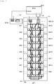
- FIG. 1 is a block diagram showing an example of the configuration of an electricity storage system according to one embodiment of the present technique.
- the electricity storage system according to an embodiment of the present technology includes an electricity storage device including a plurality of electricity storage modules, for example, 16 electricity storage modules M1 to M16 and a battery management unit BMU, a concentrator (BMU hub) HUB connected to the plurality of battery management units BMU via communication wiring Lc that is a communication path, an AC/DC converter INV (Power Conditioning System), and a system controller SYS.
- the battery management unit BMU that is a common controller is provided for the electricity storage modules M1 to M16.
- An electricity storage device including electricity storage modules M and the battery management unit BMU is referred to as a string ST.
- 14 strings ST 1 to ST 14 connected in parallel are connected to the AC/DC converter INV.
- each string ST will be referred to as a string ST as appropriate.
- the number of electricity storage modules or strings and the connection form of strings are not limited to those described above, and various settings can be made.
- the electricity storage modules M1 to M16 are connected in series. When it is unnecessary to distinguish each electricity storage module, each electricity storage module will be referred to as an electricity storage module M as appropriate.
- the connection form of the electricity storage modules M can be changed as appropriate. For example, two electricity storage modules connected in series may be connected in parallel, and eight parallel connections may be connected in series.
- power is supplied from the outside 1, and power for charging is supplied from the outside 1 to the electricity storage module M through a power line via the AC/DC converter INV.
- the outside 1 is a load, an AC power system and the like, and is set in accordance with the usage of the electricity storage system.
- the outside 1 is a 400-V three-phase three-wire power line in a factory.
- the DC power supplied from the electricity storage module M is converted to AC power and supplied to the outside 1.
- the AC power supplied from the outside 1 is converted into DC power and supplied to the electricity storage module M to charge the electricity storage module M.
- RS-232C Recommended Standard 232 version C
- RS-485 Controller Area Network
- CAN Controller Area Network
- the electricity storage module M includes an exterior case and a battery block or the like accommodated in the exterior case.
- the exterior case for example, it is desirable to use a material having high conductivity and emissivity.
- a material having high conductivity and emissivity By using a material having high conductivity and emissivity, excellent heat dissipation properties in the exterior case can be obtained.
- the opening portion of the exterior case can be minimized or eliminated, and high dust and drip resistance can be achieved.
- a material such as aluminum or an aluminum alloy, copper, a copper alloy, or the like is used as the exterior case.
- This exterior case serves as the grounded portion of a charging module M.
- a plurality of (for example, 16) lithium ion secondary batteries are connected in parallel in a battery block.
- a plurality of battery blocks is connected in series.
- the number of battery blocks and the connection form can be changed as appropriate.
- a power storage element such as a secondary battery other than a lithium ion secondary battery may be used.
- the output voltage of each lithium ion secondary battery is 3.2 V
- the battery management unit BMU that is a high-order common controller is provided for a plurality of electricity storage modules M.
- the battery management unit BMU collects data from each electricity storage module M. That is, the battery management unit BMU acquires data concerning the voltage, State Of Charge (SOC), charging current, discharge current, and battery temperature of each battery cell of the battery unit of each electricity storage module M by communication.
- the electricity storage module M and the battery management unit BMU perform bidirectional communication complying with a standard such as I2C, System Management Bus (SMBus), Serial Peripheral Interface (SPI), or Controller Area Network (CAN), which is a serial communication standard. Communication may be wired or wireless.
- SMB System Management Bus
- SPI Serial Peripheral Interface
- CAN Controller Area Network
- the battery management unit BMU controls charge permission or charge prohibition of the plurality of electricity storage modules M.
- the battery management unit BMU receives a command from the concentrator HUB by communication, and controls charge permission or charge prohibition.
- the battery management unit BMU transmits a charge permission command to the electricity storage module M for which charge permission is determined.
- the electricity storage module M turns on a charging switch element. However, when conditions of overcharge or the like of the battery are satisfied, the charging switch element is turned off.
- the electricity storage module M that has received no charge permission command turns off the charging switch element.
- the electricity storage module M has a battery unit having a plurality of lithium ion secondary batteries serially connected. Cell balance control is performed on each lithium ion secondary battery.
- the electricity storage module M further includes a voltage detection unit for detecting the voltage between the terminals of the battery unit, a temperature detection unit for detecting the temperature of the battery unit, and a current detection unit. The detected voltage, temperature, and current are converted into digital data and supplied to a battery monitor.
- the battery monitor monitors the digital voltage data and the digital temperature data to monitor the presence or absence of abnormality of the battery. For example, when the voltage indicated by digital voltage data is a voltage serving as a criterion for overcharge or a voltage serving as a criterion for overdischarge, an abnormality notification signal indicating the presence or possibility of an abnormality.
- the battery monitor also generates an abnormality notification signal when the temperature of the battery or the temperature of the entire electricity storage module M is higher than a threshold value.
- the battery monitor monitors digital current data. When the current value indicated by digital current data is larger than a threshold value, the battery monitor generates an abnormality notification signal.
- the abnormality notification signal generated by the battery monitor is transmitted to the battery management unit BMU by the communication function of the battery monitor.
- the battery monitor monitors the presence or absence of the above-mentioned abnormality and transmits digital voltage data and digital current data to the battery management unit BMU by communication. Further, the battery management unit BMU and the concentrator HUB communicate with each other to transmit the voltage data, current data, temperature data, and the like of each electricity storage module M to the concentrator HUB.
- the battery management unit BMU includes switches such as a Module controller Unit (MCU), a charge switch, and a discharge switch.
- the MCU is constituted by a Central Processing Unit (CPU) or the like having a communication function and the like and controls each electricity storage module M.
- CPU Central Processing Unit
- the battery management unit BMU notifies the concentration device HUB of the abnormality by using the communication function.
- the concentrator HUB sends a command to the battery management unit BMU by communication and appropriately performs control on the string ST such as stopping charging or discharging.
- the battery management unit BMU and the concentrator HUB are connected to each other via the communication wiring Lc.
- the plurality of battery management units BMU and the electricity storage module M are connected to each other via the communication wiring Lc.
- As the communication wiring Lc CAN, RS 232C, RS 485, or the like is used.
- the concentrator HUB communicates with the battery management unit BMU and monitors the states of a plurality of strings ST (a plurality of electricity storage modules M). Further, the concentrator HUB notifies the system controller SYS and the AC/DC converter INV of the state of the plurality of strings ST (the plurality of electricity storage modules M). In addition, the concentrator HUB receives commands from the system controller SYS and the AC/DC converter INV by communication and gives a command to the battery management unit BMU by communication to control the battery management unit BMU. Note that the concentrator HUB may have a control function and monitor and control a plurality of strings ST (a plurality of electricity storage modules M).
- the concentrator HUB holds, for example, connection information such as the number of strings ST connected in series, the number of strings ST connected in parallel, the total number of strings ST connected to each other, the number of electricity storage modules M of each string connected in series and/or the number of electricity storage modules M of each string connected in parallel, the number of the electricity storage modules M connected to each other.
- This connection information is set, for example, by an operator (user) who operates the user interface ((UI), not shown) of the concentrator HUB or sends connection information from the system controller SYS to the concentrator HUB.
- the concentrator HUB may hold the electricity storage module information associated with the present voltage, current, temperature, and the like of each electricity storage module M.
- the electricity storage module information is acquired by, for example, the concentrator HUB communicating with the battery management unit BMU.
- the concentrator HUB communicates with each of the battery management units BMU to monitor whether the voltage of each string ST has reached a predetermined voltage (a voltage lower than the upper limit voltage by a predetermined voltage or a voltage lower than the lower limit voltage by a predetermined voltage).
- a predetermined voltage a voltage lower than the upper limit voltage by a predetermined voltage or a voltage lower than the lower limit voltage by a predetermined voltage.
- the concentrator HUB communicates with each battery management unit BMU and issues a current value change instruction.
- the battery management unit BMU that has received the instruction from the concentrator HUB controls to change the current value flowing through the string ST. As a result, a current value is limited.
- the power consumption of the load connected to the outside 1 is monitored, and when the power load becomes large, the output power of the electricity storage module is supplied to the load,in addition to power from a system power, so as to level the power load.
- the system power is cut off and power is supplied from the electricity storage module to the load.
- FIG. 2 shows the interior of the container type electricity storage system having a conductive container 11 divided into two parts by a longitudinal division line. There is a passage of a width that allows a person to walk in the center of the container type electricity storage system, and the configuration shown in FIG. 2A and the configuration shown in FIG. 2B face each other across this passage.
- Strings ST1 to ST7 are provided on the side shown in FIG. 2A
- strings ST8 to ST14 are provided on the opposite side shown in FIG. 2B .
- the plurality of battery racks can be mechanically and electrically coupled to each other.
- the AC/DC converter INV, the DC input/output board 12, and the like are housed in the container 11.
- a wiring duct is provided on the ceiling portion of the container 11.
- DC power wiring Lp, the communication wiring Lc, and the like are passed through this wiring duct.
- the container 11 is connected to ground via a grounding means 13.
- the electricity storage module M of each string ST is placed on the shelf board of the battery rack and is electrically connected to the shelf board.
- the battery rack of each string ST is electrically connected to the container 11 and is grounded via the container 11.
- the AC/DC converter INV and a DC input/output board 12 are also electrically connected to the container 11 and grounded via the container 11.
- FIG. 3 shows a conventional configuration example relating to the string ST 1.
- the other strings ST2 to ST14 have the same configuration as that of the string ST1.
- the grounded portions of the electricity storage modules M 1 to M 16 are electrically connected to the shelf board of the battery rack 14.
- a grounding wire 15 of the battery rack 14 is connected to the container 11.
- the container 11 is connected to ground via the grounding means 13 as described above.
- the electricity storage modules M1 to M16 are connected in series, and the + side and the - side of the series connection are connected to the battery management unit BMU.
- the battery management unit BMU and the AC/DC converter INV are connected to each other via the DC power wiring Lp.
- the communication terminals of the electricity storage modules M1 to M16 are sequentially connected and connected to the communication terminal of the battery management unit BMU.
- the battery management unit BMU and the system controller SYS are connected to each other via the communication wiring Lc. Note that FIG. 3 omits the illustration of the concentrator HUB for collecting the communication wiring Lc of a plurality of strings.
- the grounded portion of the electricity storage module M is connected to ground via the battery rack 14 and the container 11.
- a floating capacitance is formed between the grounded portion of the electricity storage module M and ground, and there is a possibility of causing an electric shock when the electricity storage module M is accidentally touched.
- noise generated by the AC/DC converter INV or the like propagates from the DC power wiring Lp to the communication wiring Lc or may propagate to a control unit such as the battery management unit BMU of the electricity storage module M via grounding wiring to affect a control operation.
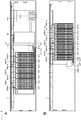
- FIG. 4 shows the interior of the container type electricity storage system having the container 11 divided into two parts by a longitudinal division line. There is a passage of a width that allows a person to walk in the center of the container type electricity storage system, and the configuration shown in FIG. 4A and the configuration shown in FIG. 4B face each other across this passage.
- the strings ST1 to ST7 are provided on the side shown in FIG. 4A
- the strings ST8 to ST14 are provided on the opposite side shown in FIG. 4B .
- the plurality of battery racks can be mechanically connected to each other, but are electrically insulated from each other.
- the AC/DC converter INV, the DC input/output board 12, and the like are housed in the container 11.
- a wiring duct is provided on the ceiling portion of the container 11.
- DC power wiring Lp, the communication wiring Lc, and the like are passed through this wiring duct.
- the distances between the direct current power wiring Lp and the communication wiring Lc are made as large as possible so that noise on the direct current power wiring Lp does not jump into the communication wiring Lc.
- the respective grounded portions of the AC/DC converter INV and the DC input/output board 12 are connected to ground outside the container 11.
- the container 11 is not grounded.
- the container 11 may be grounded so that the grounded portions of the AC / DC converter INV and the DC input/output board 12 are connected to the container 11.
- the battery rack 14 is insulated from the container 11 and further insulated from other adjacent battery racks 14.
- the battery rack 14 can be insulated by using an insulating plate, an insulating sheet, or the like.
- FIG. 5 shows the string ST1.
- the other strings ST2 to ST14 have the same configuration as that of the string ST1.
- the electricity storage module M of each string ST is placed on the shelf board of the battery rack and the grounded portions of the electricity storage modules M1 to M16 are electrically connected to the shelf board.
- the sixteen shelf boards of the battery rack 14 are connected to a ground wire Le1.
- ground wires Le1 to Le7 led out from the strings ST1 to ST7 extend to a grounding box 21a and are converted into one ground wire LE1 in the grounding box 21a.
- ground wires Le8 to Le14 led out from each of the strings ST8 to ST14 extend to a grounding box 21b, and are converted into one ground wire LE2 in the grounding box 21b.
- the ground wires LE1 and LE2 are led out to the outside of the container 11 and connected to ground outside the container 11. Accordingly, the grounded portions of the battery rack 14, the AC/DC converter INV, and the DC input/output board 12 are commonly connected to ground (same potential) outside the container.
- the electricity storage modules M1 to M16 are connected in series, and the + side and the - side of the series connection are connected to the battery management unit BMU.
- the battery management unit BMU and the AC/DC converter INV are connected to each other via the DC power wiring Lp.
- the communication terminals of the electricity storage modules M1 to M16 are sequentially connected and connected to the communication terminal of the battery management unit BMU.
- the battery management unit BMU and the system controller SYS are connected to each other via the communication wiring Lc. Note that FIG. 3 omits the illustration of the concentrator HUB for collecting the communication wiring Lc of a plurality of strings.
- the container 11 and the battery rack 14 are insulated from each other, and ground outside the battery rack 14 and the container 11 is connected to ground outside the container 11 via the ground wires Le1 to Le14 and the ground wires LE1 and LE2. Accordingly, because it is possible to perform grounding independently of the AC/DC converter INV that is a noise source, it is possible to prevent noise from propagating to the electricity storage module M via ground, thereby preventing the noise from affecting control communication to cause malfunction. In particular, providing the ground wire Le independently for each string can suppress the propagation of noise between strings. In addition, because the grounded portion of the electricity storage module M is connected to ground outside the container 11 via the battery rack 14, it is possible to prevent floating capacitance from occurring and to prevent an electric shock even if a user mistakenly touches the storage module.
- an electricity storage system 9100 for a house 9001 power is supplied from a centralized power system 9002 such as thermal power generation 9002a, nuclear power generation 9002b, or hydraulic power generation 9002c to an electricity storage device 9003 via a power network 9009, an information network 9012, a smart meter 9007, a power hub 9008, and the like.
- a power network 9009 an information network 9012, a smart meter 9007, a power hub 9008, and the like.
- power is supplied from an independent power supply such as a household power generator 9004 to the electricity storage device 9003.
- the power supplied to the electricity storage device 9003 is stored.
- the power to be used in the house 9001 is supplied using the electricity storage device 9003.
- a similar electricity storage system can be used not only for the house 9001 but also for a building.
- the house 9001 is provided with the power generator 9004, a power consumption device 9005, the electricity storage device 9003, a control device 9010 for controlling each device, the smart meter 9007, and sensors 9011 for acquiring various types of information.
- the respective devices are connected via the power network 9009 and an information network 9012.
- a solar battery, a fuel cell, or the like is used as the power generator 9004, and the generated power is supplied to the power consumption device 9005 and/or the electricity storage device 9003.
- the power consumption device 9005 includes a refrigerator 9005a, an air conditioner 9005b, a television receiver 9005c, and a bath 9005d.
- the power consumption device 9005 includes an electrically powered vehicle 9006.
- the electrically powered vehicle 9006 includes an electric vehicle 9006a, a hybrid car 9006b, and an electric motorcycle 9006c.
- the above-described battery unit according to the present technology is applied to the electricity storage device 9003.
- the electricity storage device 9003 is formed from a secondary battery or a capacitor.
- the electricity storage device 9003 is formed from a lithium-ion battery.
- the lithium ion battery may be stationary or may be used in the electrically powered vehicle 9006.
- the smart meter 9007 has a function of measuring the usage amount of commercial power and transmitting the measured usage amount to the power company.
- the power network 9009 may use any one or a combination of DC power feed, AC power feed, and non-contact power feed.
- the various sensors 9011 include, for example, a human sensor, an illuminance sensor, an object detection sensor, a power consumption sensor, a vibration sensor, a contact sensor, a temperature sensor, and an infrared sensor.
- the information acquired by the various sensors 9011 is transmitted to the control device 9010.
- the control device 9010 can grasp the state of the weather, the state of a person and the like and minimize energy consumption by automatically controlling the power consumption device 9005. Further, the control device 9010 can transmit information on the house 9001 to an external power company or the like via the Internet.
- the power hub 9008 performs processing such as branching of power lines and DC-AC conversion.
- Communication methods of the information network 9012 connected to the control device 9010 include a method using a communication interface such as a universal synchronous receiver-transmitter (UART) and a method using a sensor network based on a wireless communication standard such as Bluetooth (registered trademark), ZigBee (registered trademark), or Wi-Fi.
- the Bluetooth (registered trademark) system is applied to multimedia communication and can perform one-to-many connection communication.
- ZigBee (registered trademark) uses the physical layer of the institute of electrical and electronics engineers (IEEE) 802.15.4.
- IEEE 802.15.4 is the name of a short-range wireless network standard called personal area network (PAN) or wireless (W) PAN.
- the control device 9010 is connected to an external server 9013.
- the server 9013 may be managed by any of the house 9001, a power company, and a service provider.
- the information transmitted and received by the server 9013 includes, for example, power consumption information, life pattern information, power rate, weather information, natural disaster information, and power trade information. These pieces of information may be transmitted and received from a power consuming device (for example, a television receiver) in the home, but may be transmitted and received from a device outside the home (for example, a cellular phone). These pieces of information may be displayed on a device having a display function, for example, a television receiver, a cellular phone, or personal digital assistants (PDA).
- PDA personal digital assistants
- the control device 9010 that controls each unit is formed from a central processing unit (CPU), a random access memory (RAM), a read only memory (ROM), and the like, and is accommodated in the electricity storage device 9003 in this example.
- the control device 9010 is connected to the power storage device 9003, the household power generator 9004, the power consumption device 9005, the various types of sensors 9011, and the server 9013 via the information network 9012, and has, for example, a function of adjusting the usage amount of commercial power and the power generation amount.
- the control device 9010 may have, for example, a function of conducting power trading on the power market.
- the electricity storage device 9003 can store not only the power generated by the centralized power system 9002 such as the thermal power generation 9002a, the nuclear power generation 9002b, or the hydraulic power generation 9002c, but also the power generated by the household power generator 9004 (solar power generation and wind power generation). Therefore, even if the power generated by the household power generator 9004 fluctuates, it is possible to perform control so as to make the amount of power sent to the outside constant or discharge as necessary.
- the power storage device 9003 can be used in the following manner.
- the power obtained by photovoltaic power generation is stored in the power storage device 9003. At night, low-rate midnight power is stored in the power storage device 9003.
- the power stored in the power storage device 9003 is discharged and used in the daytime which is the time zone during which the electricity rate is high.
- control device 9010 may be accommodated in the electricity storage device 9003 or may be formed independently.
- the electricity storage system 9100 may be used for a plurality of homes in an apartment house, or may be used for a plurality of detached houses.
- the present technique is not limited to the one embodiment described above, and various modifications based on the technical idea of the present technique are possible.
- the battery units 7 are connected in series and in parallel, they may be connected only in series or in parallel.
- the configurations, methods, processes, shapes, materials, numerical values and the like mentioned in the above embodiments are merely examples, and if necessary, different configurations, methods, processes, shapes, materials, numerical values, and the like may be used.
Landscapes
- Engineering & Computer Science (AREA)
- Chemical & Material Sciences (AREA)
- General Chemical & Material Sciences (AREA)
- Electrochemistry (AREA)
- Chemical Kinetics & Catalysis (AREA)
- Power Engineering (AREA)
- Manufacturing & Machinery (AREA)
- Materials Engineering (AREA)
- Emergency Management (AREA)
- Business, Economics & Management (AREA)
- Inorganic Chemistry (AREA)
- Charge And Discharge Circuits For Batteries Or The Like (AREA)
- Supply And Distribution Of Alternating Current (AREA)
- Secondary Cells (AREA)
- Battery Mounting, Suspending (AREA)
Applications Claiming Priority (2)
| Application Number | Priority Date | Filing Date | Title |
|---|---|---|---|
| JP2016157234A JP6686785B2 (ja) | 2016-08-10 | 2016-08-10 | 電力供給装置 |
| PCT/JP2017/018947 WO2018029937A1 (ja) | 2016-08-10 | 2017-05-22 | 電力供給装置 |
Publications (2)
| Publication Number | Publication Date |
|---|---|
| EP3499604A1 true EP3499604A1 (de) | 2019-06-19 |
| EP3499604A4 EP3499604A4 (de) | 2020-04-01 |
Family
ID=61162103
Family Applications (1)
| Application Number | Title | Priority Date | Filing Date |
|---|---|---|---|
| EP17839012.6A Withdrawn EP3499604A4 (de) | 2016-08-10 | 2017-05-22 | Stromversorgungsvorrichtung |
Country Status (4)
| Country | Link |
|---|---|
| US (1) | US11183727B2 (de) |
| EP (1) | EP3499604A4 (de) |
| JP (1) | JP6686785B2 (de) |
| WO (1) | WO2018029937A1 (de) |
Families Citing this family (10)
| Publication number | Priority date | Publication date | Assignee | Title |
|---|---|---|---|---|
| DE102018114462A1 (de) * | 2018-06-15 | 2019-12-19 | Liebherr-Components Biberach Gmbh | Energiespeichervorrichtung |
| KR102381692B1 (ko) * | 2019-02-21 | 2022-03-31 | 주식회사 엘지에너지솔루션 | 배터리 랙 및 이를 포함하는 전력 저장 장치 |
| DE102019204034A1 (de) * | 2019-03-25 | 2020-10-01 | Siemens Aktiengesellschaft | Hochspannungs-Batteriespeicher mit hoher Leistungsdichte |
| KR20210030090A (ko) | 2019-09-09 | 2021-03-17 | 주식회사 엘지화학 | 배터리 랙 및 이를 포함하는 전력 저장 장치 |
| EP4386932A4 (de) * | 2022-01-19 | 2025-08-13 | Lg Energy Solution Ltd | Energiespeichersystem |
| AU2023208591A1 (en) | 2022-01-19 | 2024-04-18 | Lg Energy Solution, Ltd. | Battery system |
| CN218257821U (zh) * | 2022-06-06 | 2023-01-10 | 宁德时代新能源科技股份有限公司 | 电池仓及换电站 |
| KR102463223B1 (ko) * | 2022-07-20 | 2022-11-09 | 주식회사 태일시스템 | 무감전 비상전원 시스템 |
| CN119968734A (zh) * | 2022-09-30 | 2025-05-09 | 株式会社杰士汤浅国际 | 蓄电系统以及保护单元 |
| US12463455B2 (en) * | 2022-12-09 | 2025-11-04 | Fuji Electric Co., Ltd. | Uninterruptible power supply device and control module for uninterruptible power supply device |
Family Cites Families (7)
| Publication number | Priority date | Publication date | Assignee | Title |
|---|---|---|---|---|
| JP2013038885A (ja) * | 2011-08-06 | 2013-02-21 | Takayasu Kanemura | 自家発電システム |
| JP5849665B2 (ja) * | 2011-12-07 | 2016-02-03 | 株式会社Ihi | 蓄電システム |
| EP2800229A4 (de) * | 2011-12-26 | 2015-08-26 | Hitachi Ltd | Batteriesystem |
| EP2806501A4 (de) * | 2012-01-20 | 2015-09-30 | Yazaki Corp | Erdverbindungsstruktur und herstellungsverfahren dafür |
| US9570732B2 (en) * | 2013-11-22 | 2017-02-14 | C&C Power, Inc. | Battery system safety shield and method |
| JP6268520B2 (ja) * | 2013-12-20 | 2018-01-31 | パナソニックIpマネジメント株式会社 | 蓄電制御ユニット及びそれを用いた発電コンテナ |
| JP6455282B2 (ja) * | 2015-03-30 | 2019-01-23 | 株式会社Gsユアサ | コンテナ型蓄電ユニット |
-
2016
- 2016-08-10 JP JP2016157234A patent/JP6686785B2/ja active Active
-
2017
- 2017-05-22 WO PCT/JP2017/018947 patent/WO2018029937A1/ja not_active Ceased
- 2017-05-22 EP EP17839012.6A patent/EP3499604A4/de not_active Withdrawn
-
2019
- 2019-02-08 US US16/271,440 patent/US11183727B2/en active Active
Also Published As
| Publication number | Publication date |
|---|---|
| JP6686785B2 (ja) | 2020-04-22 |
| JP2018026255A (ja) | 2018-02-15 |
| US20190181406A1 (en) | 2019-06-13 |
| WO2018029937A1 (ja) | 2018-02-15 |
| EP3499604A4 (de) | 2020-04-01 |
| US11183727B2 (en) | 2021-11-23 |
Similar Documents
| Publication | Publication Date | Title |
|---|---|---|
| US11183727B2 (en) | Power supply apparatus | |
| US11050259B2 (en) | Power supply device and control device | |
| CN106415972B (zh) | 供电装置和供电方法 | |
| KR101320670B1 (ko) | 엘이디 조명의 충전시스템 및 정전감지 장치 | |
| US9608451B2 (en) | Electric power supplying apparatus, electric power supplying method, inverter, and electric vehicle | |
| EP2632016B1 (de) | Batteriepack, verfahren zu seiner ladung/entladung und stromverbrauchende vorrichtung | |
| CN102569705B (zh) | 蓄电设备、连接设备、蓄电系统、电子装置、和电动车辆 | |
| EP2337178A2 (de) | Energiespeichersystem eines Appartementgebäudes, integriertes Energieverwaltungssystem und Steuerverfahren für das System | |
| CN108886263B (zh) | 电力供给装置、电力供给方法及蓄电装置 | |
| EP3930134A1 (de) | System aus batterieanordnungen | |
| US20190157867A1 (en) | Plug-In Distributed Energy Resource | |
| EP2882074B1 (de) | Verwaltungsverfahren, steuerungsvorrichtung und elektrische speichervorrichtung | |
| EP3518384A1 (de) | Stromversorgungsvorrichtung stromspeichervorrichtung | |
| US11165105B2 (en) | Power supply device, power storage device, electronic device, and power system | |
| US9929571B1 (en) | Integrated energy storage system | |
| KR101395427B1 (ko) | 엘이디 조명의 충전시스템 | |
| JP2014147278A (ja) | 電源システムおよび蓄電型電源装置 | |
| US20250125627A1 (en) | Energy management systems | |
| JPWO2018230234A1 (ja) | 電力供給装置 | |
| JP2015208204A (ja) | 電力供給制御装置 | |
| WO2024238717A1 (en) | Battery systems with thermal fuse for enhanced thermal safety | |
| JP5886586B2 (ja) | Catvシステム用電源装置 |
Legal Events
| Date | Code | Title | Description |
|---|---|---|---|
| STAA | Information on the status of an ep patent application or granted ep patent |
Free format text: STATUS: THE INTERNATIONAL PUBLICATION HAS BEEN MADE |
|
| PUAI | Public reference made under article 153(3) epc to a published international application that has entered the european phase |
Free format text: ORIGINAL CODE: 0009012 |
|
| STAA | Information on the status of an ep patent application or granted ep patent |
Free format text: STATUS: REQUEST FOR EXAMINATION WAS MADE |
|
| 17P | Request for examination filed |
Effective date: 20190208 |
|
| AK | Designated contracting states |
Kind code of ref document: A1 Designated state(s): AL AT BE BG CH CY CZ DE DK EE ES FI FR GB GR HR HU IE IS IT LI LT LU LV MC MK MT NL NO PL PT RO RS SE SI SK SM TR |
|
| AX | Request for extension of the european patent |
Extension state: BA ME |
|
| DAV | Request for validation of the european patent (deleted) | ||
| DAX | Request for extension of the european patent (deleted) | ||
| A4 | Supplementary search report drawn up and despatched |
Effective date: 20200303 |
|
| RIC1 | Information provided on ipc code assigned before grant |
Ipc: H01M 2/10 20060101AFI20200226BHEP Ipc: H02J 3/32 20060101ALI20200226BHEP Ipc: H02J 3/38 20060101ALI20200226BHEP Ipc: H01M 10/44 20060101ALI20200226BHEP |
|
| STAA | Information on the status of an ep patent application or granted ep patent |
Free format text: STATUS: EXAMINATION IS IN PROGRESS |
|
| 17Q | First examination report despatched |
Effective date: 20220204 |
|
| REG | Reference to a national code |
Ref country code: DE Ref legal event code: R079 Free format text: PREVIOUS MAIN CLASS: H01M0002100000 Ipc: H02J0003380000 |
|
| GRAP | Despatch of communication of intention to grant a patent |
Free format text: ORIGINAL CODE: EPIDOSNIGR1 |
|
| STAA | Information on the status of an ep patent application or granted ep patent |
Free format text: STATUS: GRANT OF PATENT IS INTENDED |
|
| RIC1 | Information provided on ipc code assigned before grant |
Ipc: H01M 50/251 20210101ALN20230912BHEP Ipc: H01M 50/204 20210101ALI20230912BHEP Ipc: H01M 50/298 20210101ALI20230912BHEP Ipc: H01M 50/224 20210101ALI20230912BHEP Ipc: H02J 3/32 20060101ALI20230912BHEP Ipc: H02J 3/38 20060101AFI20230912BHEP |
|
| INTG | Intention to grant announced |
Effective date: 20230926 |
|
| STAA | Information on the status of an ep patent application or granted ep patent |
Free format text: STATUS: THE APPLICATION IS DEEMED TO BE WITHDRAWN |
|
| 18D | Application deemed to be withdrawn |
Effective date: 20240207 |