EP3499623B1 - Elektrochemischer reaktor mit protonenaustauschmembran für hohe temperaturen, die für lagerung bei niedrigen temperaturen geeignet ist - Google Patents
Elektrochemischer reaktor mit protonenaustauschmembran für hohe temperaturen, die für lagerung bei niedrigen temperaturen geeignet ist Download PDFInfo
- Publication number
- EP3499623B1 EP3499623B1 EP18208316.2A EP18208316A EP3499623B1 EP 3499623 B1 EP3499623 B1 EP 3499623B1 EP 18208316 A EP18208316 A EP 18208316A EP 3499623 B1 EP3499623 B1 EP 3499623B1
- Authority
- EP
- European Patent Office
- Prior art keywords
- flow
- cooling fluid
- manifold
- seal
- flow channel
- Prior art date
- Legal status (The legal status is an assumption and is not a legal conclusion. Google has not performed a legal analysis and makes no representation as to the accuracy of the status listed.)
- Active
Links
Images


Classifications
-
- H—ELECTRICITY
- H01—ELECTRIC ELEMENTS
- H01M—PROCESSES OR MEANS, e.g. BATTERIES, FOR THE DIRECT CONVERSION OF CHEMICAL ENERGY INTO ELECTRICAL ENERGY
- H01M8/00—Fuel cells; Manufacture thereof
- H01M8/02—Details
- H01M8/0202—Collectors; Separators, e.g. bipolar separators; Interconnectors
- H01M8/0258—Collectors; Separators, e.g. bipolar separators; Interconnectors characterised by the configuration of channels, e.g. by the flow field of the reactant or coolant
- H01M8/0263—Collectors; Separators, e.g. bipolar separators; Interconnectors characterised by the configuration of channels, e.g. by the flow field of the reactant or coolant having meandering or serpentine paths
-
- H—ELECTRICITY
- H01—ELECTRIC ELEMENTS
- H01M—PROCESSES OR MEANS, e.g. BATTERIES, FOR THE DIRECT CONVERSION OF CHEMICAL ENERGY INTO ELECTRICAL ENERGY
- H01M8/00—Fuel cells; Manufacture thereof
- H01M8/02—Details
- H01M8/0271—Sealing or supporting means around electrodes, matrices or membranes
- H01M8/0276—Sealing means characterised by their form
-
- H—ELECTRICITY
- H01—ELECTRIC ELEMENTS
- H01M—PROCESSES OR MEANS, e.g. BATTERIES, FOR THE DIRECT CONVERSION OF CHEMICAL ENERGY INTO ELECTRICAL ENERGY
- H01M8/00—Fuel cells; Manufacture thereof
- H01M8/02—Details
- H01M8/0202—Collectors; Separators, e.g. bipolar separators; Interconnectors
- H01M8/0247—Collectors; Separators, e.g. bipolar separators; Interconnectors characterised by the form
-
- H—ELECTRICITY
- H01—ELECTRIC ELEMENTS
- H01M—PROCESSES OR MEANS, e.g. BATTERIES, FOR THE DIRECT CONVERSION OF CHEMICAL ENERGY INTO ELECTRICAL ENERGY
- H01M8/00—Fuel cells; Manufacture thereof
- H01M8/02—Details
- H01M8/0202—Collectors; Separators, e.g. bipolar separators; Interconnectors
- H01M8/0267—Collectors; Separators, e.g. bipolar separators; Interconnectors having heating or cooling means, e.g. heaters or coolant flow channels
-
- H—ELECTRICITY
- H01—ELECTRIC ELEMENTS
- H01M—PROCESSES OR MEANS, e.g. BATTERIES, FOR THE DIRECT CONVERSION OF CHEMICAL ENERGY INTO ELECTRICAL ENERGY
- H01M8/00—Fuel cells; Manufacture thereof
- H01M8/02—Details
- H01M8/0271—Sealing or supporting means around electrodes, matrices or membranes
- H01M8/0273—Sealing or supporting means around electrodes, matrices or membranes with sealing or supporting means in the form of a frame
-
- H—ELECTRICITY
- H01—ELECTRIC ELEMENTS
- H01M—PROCESSES OR MEANS, e.g. BATTERIES, FOR THE DIRECT CONVERSION OF CHEMICAL ENERGY INTO ELECTRICAL ENERGY
- H01M8/00—Fuel cells; Manufacture thereof
- H01M8/02—Details
- H01M8/0271—Sealing or supporting means around electrodes, matrices or membranes
- H01M8/0276—Sealing means characterised by their form
- H01M8/0278—O-rings
-
- H—ELECTRICITY
- H01—ELECTRIC ELEMENTS
- H01M—PROCESSES OR MEANS, e.g. BATTERIES, FOR THE DIRECT CONVERSION OF CHEMICAL ENERGY INTO ELECTRICAL ENERGY
- H01M8/00—Fuel cells; Manufacture thereof
- H01M8/02—Details
- H01M8/0271—Sealing or supporting means around electrodes, matrices or membranes
- H01M8/028—Sealing means characterised by their material
-
- H—ELECTRICITY
- H01—ELECTRIC ELEMENTS
- H01M—PROCESSES OR MEANS, e.g. BATTERIES, FOR THE DIRECT CONVERSION OF CHEMICAL ENERGY INTO ELECTRICAL ENERGY
- H01M8/00—Fuel cells; Manufacture thereof
- H01M8/10—Fuel cells with solid electrolytes
- H01M8/1004—Fuel cells with solid electrolytes characterised by membrane-electrode assemblies [MEA]
-
- H—ELECTRICITY
- H01—ELECTRIC ELEMENTS
- H01M—PROCESSES OR MEANS, e.g. BATTERIES, FOR THE DIRECT CONVERSION OF CHEMICAL ENERGY INTO ELECTRICAL ENERGY
- H01M8/00—Fuel cells; Manufacture thereof
- H01M8/10—Fuel cells with solid electrolytes
- H01M8/1007—Fuel cells with solid electrolytes with both reactants being gaseous or vaporised
-
- H—ELECTRICITY
- H01—ELECTRIC ELEMENTS
- H01M—PROCESSES OR MEANS, e.g. BATTERIES, FOR THE DIRECT CONVERSION OF CHEMICAL ENERGY INTO ELECTRICAL ENERGY
- H01M8/00—Fuel cells; Manufacture thereof
- H01M8/24—Grouping of fuel cells, e.g. stacking of fuel cells
- H01M8/2465—Details of groupings of fuel cells
- H01M8/2483—Details of groupings of fuel cells characterised by internal manifolds
-
- Y—GENERAL TAGGING OF NEW TECHNOLOGICAL DEVELOPMENTS; GENERAL TAGGING OF CROSS-SECTIONAL TECHNOLOGIES SPANNING OVER SEVERAL SECTIONS OF THE IPC; TECHNICAL SUBJECTS COVERED BY FORMER USPC CROSS-REFERENCE ART COLLECTIONS [XRACs] AND DIGESTS
- Y02—TECHNOLOGIES OR APPLICATIONS FOR MITIGATION OR ADAPTATION AGAINST CLIMATE CHANGE
- Y02E—REDUCTION OF GREENHOUSE GAS [GHG] EMISSIONS, RELATED TO ENERGY GENERATION, TRANSMISSION OR DISTRIBUTION
- Y02E60/00—Enabling technologies; Technologies with a potential or indirect contribution to GHG emissions mitigation
- Y02E60/30—Hydrogen technology
- Y02E60/50—Fuel cells
Definitions
- the invention relates to electrochemical reactors with a proton exchange membrane, such as electrolysers for the production of dihydrogen by electrolysis of water, or fuel cells for the production of electricity.
- Proton exchange membrane electrochemical reactors are used at an operating temperature below 300 ° C.
- the proton exchange membrane forms a solid electrolyte.
- polybenzimidazole type membranes loaded with phosphoric acid are generally used.
- a fuel cell usually includes a stack of elementary cells in which an electrochemical reaction takes place between two reagents which are introduced continuously.
- the fuel is brought into contact with the anode, the oxidant is brought into contact with the cathode.
- the reaction is subdivided into two half-reactions, which take place on the one hand at the anode / membrane interface and on the other hand at the cathode / membrane interface.
- Half-reactions can only take place if there is an ionic conductor between the two electrodes and an electronic conductor.
- the fluids are brought into contact with the reaction zones from inlet and outlet manifolds which generally pass right through the stack.
- the fluids are generally guided between a collector and their reaction zone by flow channels of a bipolar plate, also having an electrical conduction function and a function of transmission of a clamping force of the cell stack.
- Each collector is surrounded by a seal avoiding the mixing of the various fluids circulating in the fuel cell.
- Each cell has injection means through the seals to bring the fluid concerned, from the manifold to the reaction zone.
- a peripheral seal is placed at the periphery of each bipolar plate and thus surrounds a middle part of the stack including the reaction zone and the flow collectors. This peripheral seal seals the various flow circuits between them and vis-à-vis the outside.
- Such a fuel cell therefore uses at least two different types of seals: the peripheral seals and the seals surrounding the flow collectors.
- the internal temperature of the fuel cell is regulated at its usual operating temperature, since the heat losses from the electrochemical reaction are much greater than the heat exchanges at its periphery.
- An internal temperature of the fuel cell is therefore lower than its usual operating temperature only outside of its operation: during shutdown, storage or maintenance phases for example.
- the invention aims to solve one or more of these drawbacks.
- the invention thus relates to an electrochemical reactor, as defined in the appended claims.
- the invention also relates to a system as defined in the appended claims.
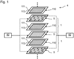
- the figure 1 is a schematic exploded perspective view of a stack of cells 1 of a fuel cell 4.
- the fuel cell 4 comprises several cells 1 superimposed.
- Cells 1 are of the proton exchange membrane or polymer electrolyte membrane type.
- the fuel cell 4 comprises a fuel source 40.
- the fuel source 40 here supplies dihydrogen to an inlet of each cell 1.
- the fuel cell 4 also includes a fuel source 42.
- the fuel source 42 here supplies air an inlet to each cell 1, the oxygen in the air being used as an oxidant.
- Each cell 1 also includes exhaust channels.
- One or more cells 1 also have a cooling circuit for the reactive zone.
- Each cell 1 comprises a membrane / electrodes 110 or AME 110 assembly.
- a membrane / electrodes 110 assembly comprises a solid electrolyte 113, a cathode (not shown) and an anode 111 placed on either side of the electrolyte and fixed on this electrolyte 113.
- the electrolyte layer 113 forms a membrane allowing proton conduction while being impermeable to the gases present in the cell.
- the electrolyte layer also prevents passage of electrons between the anode 111 and the cathode.
- the electrolyte 113 is here configured to be used at an operating temperature greater than 100 ° C., typically an operating temperature of 180 ° C.
- Such an electrolyte 113 can for example be made of polybenzimidazole (PBI) doped with phosphoric acid
- a bipolar plate 5 is placed between each pair of adjacent AMEs.
- a bipolar plate 5 forms a reagent flow guide.
- Each bipolar plate 5 here defines channels anode flow channels and cathode flow channels on opposite external faces.
- Bipolar plates 5 also define coolant flow channels between two successive membrane / electrode assemblies.
- the bipolar plates 5 can each be formed in a manner known per se from two conductive metal sheets assembled, for example from stainless steel, or from titanium alloy, aluminum alloy, nickel alloy or tantalum alloy. Each sheet then defines a respective external face.
- the bipolar plates 5 can also be obtained by any other method, for example molding or injection from carbon-polymer composites. The bipolar plates 5 can thus also be formed in one piece.
- Each cell 1 may further comprise a gas diffusion layer (not shown) disposed between the anode and a bipolar plate, and another gas diffusion layer disposed between the cathode and another bipolar plate.
- the membrane / electrode assemblies 110 may include reinforcements, not illustrated here.
- the bipolar plates 5 have in particular a function for guiding the flow of reagents on either side of the AME 110.
- the dihydrogen is ionized to produce protons which cross the AME 110.
- the electrons produced by this reaction are collected by a bipolar plate 5.
- the electrons produced are then applied to an electric charge connected to the fuel cell 4 to form an electric current.
- oxygen is reduced and reacts with the protons to form water.
- the reactions at the anode and the cathode are governed as follows: 2 H 2 ⁇ 4 H + + 4 e - at the anode; 4 H + + 4 e - + O 2 ⁇ 2 H 2 O at the cathode.
- a cell 1 of the fuel cell 4 usually generates a DC voltage between the anode and the cathode of the order of 1V.
- the oxidant source 42 typically comprises a compressor for introducing air at a given pressure at the inlet of the cells 1.
- a compressor receives, for example, an air pressure setpoint, the air pressure being able to be regulated by a variable compressor speed.
- the stack of bipolar plates 5 and of membrane / electrode assemblies 110 is intended to form a plurality of flow collectors.
- respective orifices are provided through the bipolar plates 5 and through the membrane / electrode assemblies 110.
- the orifices of the bipolar plates 5 and of the membrane / electrode assemblies 110 are arranged opposite so as to form the different flow collectors.
- the figure 2 is a schematic top view of a bipolar plate 5 given by way of example, for a fuel cell according to an embodiment of the invention.
- a sheet 50 of the bipolar plate 5 is thus illustrated in top view, provided with different seals. The seals are pressed against an AME 110, not shown in this figure.
- the bipolar plates 5 thus have orifices 591 and 592 at a first longitudinal end, and orifices 595 and 596 at a second longitudinal end.
- the bipolar plates 5 In a central region 52, the bipolar plates 5 have an orifice 593 near the orifices 591 and 592, and an orifice 594 near the orifices 595 and 596.
- the orifices 591 to 596 are surrounded by seals 511 to 516 respectively.
- the orifice 591 is used for example to form a fuel supply manifold
- the orifice 596 is used for example to form a manifold for evacuating combustion residues and unused fuel.
- the orifice 593 is used for example to form a coolant supply manifold for the central region 52
- the orifice 594 is used for example to form a manifold for discharging this coolant.
- the orifice 592 is used, for example, to form a collector for supplying oxidant
- the orifice 595 is used, for example, to form a collector for discharging produced water and unused oxidant.
- the central region 52 generally corresponds to a reactive region of the fuel cell.
- the central zone 52 comprises flow channels 522 illustrated diagrammatically, for example anodic flow channels delimited by walls 521.
- a peripheral seal 517 surrounds all of the orifices or collectors 591 to 596 and the middle part 52.
- a seal 518 surrounds the middle part 52.
- An intermediate zone 57 is thus formed between the seals 517 and 518, the orifices 591, 592, 595 and 596 crossing the intermediate zone 57.
- the seals 511 to 518 are compressed between a sheet 50 of the bipolar plate 5 and an AME.
- the bipolar plate 5 has substantially a rectangular shape.
- the seals 517 and 518 here also have a rectangular shape, which will be used to detail a simple configuration of the invention.
- the coolant flow circuits 53, 54, 55 and 56 are configured to form a thermal gradient between the peripheral seal 517 and the intermediate seal 518, when the fuel cell 4 is in operation.
- Each of the flow circuits 53 to 56 comprises on the one hand a flow channel extending along the peripheral seal 517, on the other hand a flow channel extending along the intermediate seal 518, and a another flow channel connecting these.
- the schematic configuration of the flow circuit 54 is illustrated in figure 3 .
- the flow circuit 54 has a flow channel 541, having a first end 546 connected to a coolant intake manifold 597, and a second end 547 opposite the end 546.
- the flow channel 541 extends parallel to one side of the peripheral seal 517, adjacent thereto.
- the flow circuit 54 also includes a flow channel 545, having a first end 548 connected to a coolant exhaust manifold 598, and a second end 549 opposite the end 548.
- the flow channel 545 extends parallel to one side of the intermediate seal 518, adjacent to it.
- the flow circuit 54 also includes a flow channel 543, connecting the end 547 to the end 549.
- the flow channel 543 is separated from the flow channel 541 by a wall 542.
- the wall 542 prevents in particular the flow passing directly from the end 546 to the end 549.
- the flow channel 543 is separated from the flow channel 545 by a wall 544.
- the wall 544 prevents in particular the flow from passing directly from the end 547 towards end 548.
- the coolant flow collectors are connected to a cooling and injection circuit.
- the cooling circuit is in particular configured to cool the cooling fluid taken from a collector 598 via an exchanger, and configured to drive this cooling fluid from the exchanger to the collector 597.
- a coolant is introduced at low temperature into the cooling circuits 53 to 57 via the collectors 597.
- the coolant passes through the flow channels along the seal 517, and thus cool the seal 517 for the maintain at the temperature included in the range of use of its material.
- the seal 517 thus retains its sealing properties even when the fuel cell 4 is in operation.
- the peripheral seal 517 and the intermediate seal 518 are advantageously made of different materials, having different temperature ranges of use.
- the material of the peripheral seal 517 includes for example a temperature of -20 ° C in its range of use, or even -60 ° C in its range of use, in order to be able to store the fuel cell 4 at low temperature, without problem of sealing vis-à-vis the environment.
- the material of the intermediate seal 518 includes, for example, a temperature of 180 ° C. in its range of use, or even a temperature of 200 ° C. in its range of use. Such a temperature corresponds to an operating temperature of certain high temperature fuel cells.
- the operating temperature of the fuel cell 4 should for example be higher than the glass transition temperature of the seal 518, and lower than its destruction temperature.
- the invention thus proves to be particularly suitable for electrochemical reactors operating at a temperature above 100 ° C., for which the operating temperature is therefore very different from the storage temperature for which these electrochemical reactors must be sized.
- the invention thus makes it possible to produce seals 517 and 518 in different materials, having different temperature ranges of use.
- a greater number of materials is available on the one hand for the seal 517, and on the other hand for the seal 518.
- This in particular makes it possible to have more technological choices for the seals 517 and 518, in order to respond chemical compatibility, mechanical properties, or even lifespan requirements.
- the seals 511, 512, 515 and 516 are advantageously made of the same material as the seal 517.
- the flow circuits 53 to 56 are configured to have a cumulative length of the sections along the joint 517 (sections extending from one end connected to a manifold 597 at an opposite end) extending over at least 60% of the length of the peripheral joint. Such a dimension makes it possible to guarantee optimal cooling of the seal 517 to guarantee its sealing.
- the collectors 598 are advantageously surrounded by seals made of the same material as the intermediate seal 518.
- seals 518 may prove to be leaktight at a very low storage temperature of the fuel cell 4.
- the fuel cell 4 does not however present a risk of external pollution, due to the presence of the seal 517 for which this temperature is within its range of use.
- the cooling fluid circulating in the circuits 53 to 56 is compatible with the other flow circuits, namely the flow circuits of reagents or the flow circuits of other heat transfer fluids.
- This cooling fluid can for example be air or water.
- air as a cooling fluid advantageously makes it possible to collect any oxidant leaks at the periphery of the middle zone 52. Depleted air recovered from an exhaust manifold (typically including between them 8 and 12% of said oxygen) is particularly suitable, due to the low risk of ignition with a leak of dihydrogen fuel.
- the figure 4 schematically illustrates an example of a cooling and injection circuit 6 of cooling fluid according to a variant of the invention.
- the cooling and injection circuit 6 is connected to a stack 11 of electrochemical cells.
- the cooling and injection circuit 6 here comprises an independent cooling and injection circuit for the coolant of the seals 517 and 518.
- the cooling and injection circuit 6 here comprises another independent cooling and injection circuit for the cooling fluid of the middle zone 52. This configuration typically corresponds to that detailed with reference to the figure 2 .
- the cooling fluid for the central zone 52 may be different from that used for the seals 517 and 518.
- the cooling and injection circuit 6 is applied here for a liquid cooling fluid.
- the cooling circuit for the seals 517 and 518 here comprises a pump 61, the inlet of which is connected to the manifold 598.
- the cooling circuit for the seals 517 and 518 also comprises a heat exchanger 62, the inlet of which is connected to the outlet of the pump 61.
- the outlet of the exchanger 62 is connected to the collector 597.
- the heat exchanger 62 is intended to dissipate the heat of the coolant recovered from a collector 598.
- the coolant introduced into a manifold 597 therefore makes it possible then to cool the peripheral seal 517 to keep it within its operating temperature range.
- the cooling circuit for the middle zone 52 here comprises a pump 63 whose input is connected to the manifold 594.
- the cooling circuit for the middle zone 52 also comprises a heat exchanger 64, whose input is connected to the output of the pump 63.
- the output of the exchanger 64 is connected to the manifold 593.
- the figure 5 schematically illustrates an example of a cooling and injection circuit 6 of cooling fluid according to another variant of the invention.
- the cooling and injection circuit 6 is connected to a stack 11 of electrochemical cells.
- the cooling and injection circuit 6 here comprises a cooling and injection circuit for the coolant of the seals 517 and 518, connected to the cooling and injection circuit for the middle zone 52.
- the coolant for the central zone 52 is here identical to that used for the seals 517 and 518.
- the circuits 53 to 56 are connected to the collector 594 rather than to the collector 598.
- the cooling and injection circuit 6 is applied here for a liquid cooling fluid.
- the collector 598 collects liquid for cooling the seals 517 and 518 and coolant for the central zone 52.
- the circuit 6 comprises a pump 63 whose inlet is connected to the collector 598.
- the circuit 6 also comprises an exchanger thermal 64, the input of which is connected to the output of the pump 63.
- the output of the exchanger thermal 64 is connected to the collector 593, via a first branch. This first branch is intended to conduct coolant to the middle zone 52 in the stack 11.
- the outlet of the heat exchanger 64 is also connected to the manifold 597, via a second branch. This second branch is intended to conduct coolant for the joints 517 and 518 in the stack 11.
- This second branch including a heat exchanger 62 disposed between the manifold 597 and the outlet of the heat exchanger 64.
- the outlet of the exchanger 62 is connected to the collector 597.
- the heat exchanger 62 is intended to dissipate the heat of the coolant recovered from a collector 598.
- the coolant introduced at the level of a collector 597 therefore makes it possible then to cool the peripheral seal 517 in order to maintain it within its operating temperature range.
- Such a configuration makes it possible in particular to benefit from a heat exchanger 64 having a larger dimension than the heat exchanger 62, and thus making it possible to achieve high cooling of the coolant.
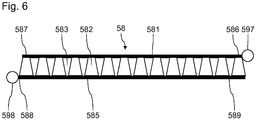
- the figure 6 schematically illustrates an intermediate cooling circuit 58 for a fuel cell 4 according to another embodiment of the invention.
- the flow circuit 58 includes a flow channel 581,
- the circuit 58 (other circuits 58 can be distributed around the intermediate seal 518) has a first end 586 connected to the coolant intake manifold 597, and a second end 587 opposite the end 586.
- the channel d flow 581 extends parallel to one side of the peripheral seal 517, adjacent thereto.
- the flow circuit 58 also includes a flow channel 585, having a first end 588 connected to the coolant exhaust manifold 598, and a second end 589 opposite the end 588.
- the flow channel 585 extends parallel to one side of the intermediate seal 588, adjacent to it.
- the end 586 of the flow channel 581 is positioned near the second end 589 of the second flow channel 585.
- flow channels 583 are provided between the flow channels 581 and 585. These flow channels 583 are distributed along the first flow channel 581 and each connect the flow channel 581 to the flow channel 585, so that a fluid introduced at the level of the manifold 597 must pass through a channel d flow 583 to join manifold 598. Channels 583 are configured to induce pressure drops in a flow of fluid between the flow channels 581 and 585, in order to favor the formation of a temperature gradient between these flow channels 581 and 585.
- the flow channels 583 are here delimited by walls 582 positioned between the channels 581 and 585, so as to limit the section of the channels 583. The walls 582 here form a gradual narrowing of the section starting from the channel 581 towards the channel 585.
- the collectors 591, 592, 595 and 596 are positioned in the intermediate zone 57. It is however also possible to envisage collectors 591, 592, 595 and 596 surrounded by the seal 518.
- the seals 511, 512, 515 and 516 are then made of the same material as the seal 518. If these seals 511, 512, 515 and 516 are not leaktight at a storage temperature, provision may be made for the flow channels intended to be crossed by reagents to be purged beforehand before proceeding with the storage of the fuel cell 4, and therefore before cooling these joints to a temperature below their range of use.
- the invention has been described for an example in which the coolant flow channels for the seals 517 and 518 are positioned on an external face of the bipolar plate 5. It can also be provided that such flow channels are formed on the two external faces of the bipolar plate 5. It can also be provided that these cooling flow channels of the seals 517 and 518 are formed inside the bipolar plate, in a sealed manner with respect to the flow channels coolant in the active area disposed in the middle area 52.
- the invention has been described previously for application to fuel cells.
- the invention is of course also applicable to other electrochemical reactors with a proton exchange membrane, for example electrolysers.
- the bipolar plates 5 can be replaced by polarized flow guides at respective electrolysis voltages.
- the invention has been described previously for a fuel cell supplied with dihydrogen fuel.
- the invention is of course also applicable to fuel cells using other types of fuel, for example methanol.
- the coolant passing through the cooling circuits 53 to 56 can be one of the reactants passing through the central zone 52. It can then be provided that one of the reactants is introduced into the circuits 53 to 56 via a manifold 597 , recovered at a collector 598, then reintroduced at the collector 591 or 592 if necessary. We can also provide that one of the reagents is recovered from the collector 595 or 596 if necessary, then introduced into the circuits 53 to 56 via a collector 597, after having passed through a heat exchanger. A water recovery device can be included in circuit 6 if it is desired to reintroduce only the gas phase at a reagent outlet.
Landscapes
- Life Sciences & Earth Sciences (AREA)
- Engineering & Computer Science (AREA)
- Manufacturing & Machinery (AREA)
- Sustainable Development (AREA)
- Sustainable Energy (AREA)
- Chemical & Material Sciences (AREA)
- Chemical Kinetics & Catalysis (AREA)
- Electrochemistry (AREA)
- General Chemical & Material Sciences (AREA)
- Fuel Cell (AREA)
- Electrolytic Production Of Non-Metals, Compounds, Apparatuses Therefor (AREA)
Claims (13)
- Elektrochemischer Reaktor (4), der Folgendes beinhaltet:- eine Strömungsführung (5);- eine Membran-Elektroden-Einheit (110);- eine Umfangsdichtung (517), die zwischen der Strömungsführung (5) und der Membran-Elektroden-Einheit (110) angeordnet ist;dadurch gekennzeichnet, dass er ferner Folgendes beinhaltet:- eine Zwischendichtung (518), die zwischen der Strömungsführung (5) und der Membran-Elektroden-Einheit (110) angeordnet ist, wobei die Zwischendichtung von der Umfangsdichtung (517) umgeben ist und eine reaktive Zone (52) des elektrochemischen Reaktors umgibt;- mindestens einen ersten Strömungsweg (54) eines Kühlfluids, der zwischen der Umfangsdichtung (517) und der Zwischendichtung (518) angeordnet ist, wobei der Strömungsweg Folgendes beinhaltet:- einen ersten Strömungskanal (541), der sich entlang der Umfangsdichtung (517) zwischen einem ersten Ende (546), das mit einem ersten Kühlfluidsammler (597) verbunden ist, und einem zweiten, dem ersten entgegengesetzten Ende (547) erstreckt;- einen zweiten Strömungskanal (545), der sich entlang der Zwischendichtung (518) zwischen einem ersten Ende (548), das mit einem zweiten Kühlfluidsammler (598) verbunden ist, und einem zweiten, dem ersten entgegengesetzten Ende (549) erstreckt; und- entweder einen dritten Strömungskanal (543), der das jeweilige zweite Ende (547, 549) des ersten und des zweiten Strömungskanals (541, 545) miteinander verbindet, sodass ein im Bereich des ersten Sammlers eingespeistes Fluid den dritten Strömungskanal (543) durchqueren muss, um den zweiten Sammler zu erreichen;- oder vierte Strömungskanäle (583), die entlang dem ersten Strömungskanal (581) verteilt sind und jeweils den ersten Strömungskanal mit dem zweiten Strömungskanal (585) verbinden, sodass ein im Bereich des ersten Sammlers (597) eingespeistes Fluid einen vierten Strömungskanal (583) durchqueren muss, um den zweiten Sammler (598) zu erreichen, wobei das erste Ende (586) des ersten Strömungskanals in der Nähe des zweiten Endes (589) des zweiten Strömungskanals (585) positioniert ist, wobei die vierten Strömungskanäle dazu konfiguriert sind, Druckverluste in einer Fluidströmung zwischen dem ersten und dem zweiten Strömungskanal hervorzurufen.
- Elektrochemischer Reaktor (4) nach Anspruch 1, wobei die Umfangsdichtung (517) und die Zwischendichtung (518) aus unterschiedlichen Materialien bestehen, wobei das Material der Umfangsdichtung (517) eine Temperatur von -20 °C in seinem Einsatzbereich umfasst, wobei das Material der Zwischendichtung (518) eine Temperatur von 180 °C in seinem Einsatzbereich umfasst.
- Elektrochemischer Reaktor (4) nach Anspruch 1 oder 2, wobei fünfte Kühlfluidströmungskanäle im Inneren der Bipolarplatte (5) in der Vertikalen der reaktiven Zone (52) bereitgestellt sind, wobei der Kühlfluidströmungsweg (53) und die fünften Kühlfluidströmungskanäle ein gleiches Kühlfluid umfassen.
- Elektrochemischer Reaktor (4) nach den Ansprüchen 2 und 3, wobei die fünften Kühlfluidströmungskanäle mit einem dritten und einem vierten Sammler (593, 594), die sich in der reaktiven Zone (52) befinden, in Kommunikation stehen, wobei der dritte und der vierte Sammler von Dichtungen (513, 514) umgeben sind, die aus dem gleichen Material wie die Zwischendichtung (518) gebildet sind.
- Elektrochemischer Reaktor (4) nach einem der vorhergehenden Ansprüche, wobei der Kühlfluidströmungsweg (53) ein Kühlfluid umfasst, das aus der Gruppe ausgewählt ist, die aus Luft, Diwasserstoff, Wasser und Glykol besteht.
- Elektrochemischer Reaktor (4) nach einem der vorhergehenden Ansprüche, wobei sich der erste Sammler (597) näher an der Umfangsdichtung (517) als an der Zwischendichtung (518) befindet.
- Elektrochemischer Reaktor (4) nach einem der vorhergehenden Ansprüche, wobei sich der zweite Sammler (598) näher an der Zwischendichtung (518) als an der Umfangsdichtung (517) befindet.
- Elektrochemischer Reaktor (4) nach einem der vorhergehenden Ansprüche, der mehrere zwischen der Umfangsdichtung (517) und der Zwischendichtung (518) angeordnete Kühlfluidströmungswege (54, 55, 56) beinhaltet, die dem ersten Kühlfluidströmungsweg (54) ähnlich sind, wobei die kumulierte Länge der ersten Strömungskanäle dieser Strömungswege mindestens gleich 60 % der Länge der Umfangsdichtung (517) ist.
- Elektrochemischer Reaktor nach einem der vorhergehenden Ansprüche, wobei der erste Strömungskanal (541) zwischen der Umfangsdichtung (517) und dem zweiten Strömungskanal (545) angeordnet ist.
- System, das einen elektrochemischen Reaktor nach einem der vorhergehenden Ansprüche umfasst, das ferner einen Kompressor (61), der mit dem ersten und dem zweiten Sammler (597, 598) verbunden ist, beinhaltet, wobei der Kompressor dazu konfiguriert ist, Druckluft in den ersten Sammler einzuspeisen.
- System nach Anspruch 10, das ferner einen Wärmetauscher (62) beinhaltet, der einen Eingang, der mit einem Ausgang des Kompressors verbunden ist, und einen Ausgang, der mit dem ersten Kühlfluidsammler verbunden ist, aufweist.
- System nach Anspruch 11, wobei der Eingang des Kompressors (62) mit einem Auslasssammler eines kathodischen Reaktanten verbunden ist.
- System nach Anspruch 10, 11 oder 12, wobei das Kühlfluid Luft ist, wobei die Kühlfluidströmung durch den ersten Strömungskanal einen Druckverlust aufweist, der kleiner als der der Kühlfluidströmung durch die vierten Strömungskanäle (583) ist.
Applications Claiming Priority (1)
| Application Number | Priority Date | Filing Date | Title |
|---|---|---|---|
| FR1762067A FR3074970B1 (fr) | 2017-12-13 | 2017-12-13 | Reacteur electrochimique a membrane echangeuse de protons a haute temperature adapte pour stockage basse temperature |
Publications (2)
| Publication Number | Publication Date |
|---|---|
| EP3499623A1 EP3499623A1 (de) | 2019-06-19 |
| EP3499623B1 true EP3499623B1 (de) | 2020-06-03 |
Family
ID=61913281
Family Applications (1)
| Application Number | Title | Priority Date | Filing Date |
|---|---|---|---|
| EP18208316.2A Active EP3499623B1 (de) | 2017-12-13 | 2018-11-26 | Elektrochemischer reaktor mit protonenaustauschmembran für hohe temperaturen, die für lagerung bei niedrigen temperaturen geeignet ist |
Country Status (4)
| Country | Link |
|---|---|
| US (1) | US10797326B2 (de) |
| EP (1) | EP3499623B1 (de) |
| JP (1) | JP2019149367A (de) |
| FR (1) | FR3074970B1 (de) |
Families Citing this family (2)
| Publication number | Priority date | Publication date | Assignee | Title |
|---|---|---|---|---|
| FR3076953A1 (fr) * | 2018-01-18 | 2019-07-19 | Commissariat A L'energie Atomique Et Aux Energies Alternatives | Ensemble de cellules pour adaptation de puissance de reacteurs electrochimiques |
| JP2023538306A (ja) * | 2020-08-14 | 2023-09-07 | オーミアム インターナショナル, インコーポレイテッド | ハイブリッド双極プレートおよびそれを作製する方法 |
Family Cites Families (13)
| Publication number | Priority date | Publication date | Assignee | Title |
|---|---|---|---|---|
| US6423439B1 (en) * | 1997-07-16 | 2002-07-23 | Ballard Power Systems Inc. | Membrane electrode assembly for an electrochemical fuel cell |
| US7459227B2 (en) * | 2003-04-18 | 2008-12-02 | General Motors Corporation | Stamped fuel cell bipolar plate |
| CA2479325C (en) * | 2003-08-28 | 2010-08-10 | Honda Motor Co., Ltd. | Fuel cell having closure seal |
| US7067214B2 (en) * | 2003-10-27 | 2006-06-27 | Utc Fuel Cells, Llc | PEM fuel cell stack assembly with isolated internal coolant manifold |
| US7306874B2 (en) * | 2003-11-20 | 2007-12-11 | General Motors Corporation | PEM fuel cell stack with coated flow distribution network |
| US7226687B2 (en) * | 2004-05-08 | 2007-06-05 | Meacham G B Kirby | Fuel cell assemblies using metallic bipolar separators |
| JP4562501B2 (ja) * | 2004-11-25 | 2010-10-13 | 本田技研工業株式会社 | 燃料電池 |
| FR2902930B1 (fr) * | 2006-06-21 | 2009-11-27 | Commissariat Energie Atomique | Plaque bipolaire pour pile a combustible, et pile a combustible a distribution de fluide amelioree mettant en oeuvre de telles plaques |
| JP5318382B2 (ja) * | 2007-08-07 | 2013-10-16 | 本田技研工業株式会社 | 燃料電池スタック |
| US8785068B2 (en) * | 2009-03-18 | 2014-07-22 | Honda Motor Co., Ltd. | Fuel cell |
| CA2866798C (en) | 2012-03-09 | 2017-07-04 | Nissan Motor Co., Ltd. | Seal plate and fuel cell stack using the same |
| FR2997562B1 (fr) | 2012-10-30 | 2017-01-13 | Michelin & Cie | Plaque bipolaire pour pile a combustible |
| FR3014246B1 (fr) * | 2013-12-04 | 2016-01-01 | Commissariat Energie Atomique | Joint d'etancheite pour dispositif electrochimique, procede de fabrication et d'assemblage du joint et ce dispositif. |
-
2017
- 2017-12-13 FR FR1762067A patent/FR3074970B1/fr not_active Expired - Fee Related
-
2018
- 2018-11-26 EP EP18208316.2A patent/EP3499623B1/de active Active
- 2018-12-06 US US16/211,774 patent/US10797326B2/en active Active
- 2018-12-10 JP JP2018230685A patent/JP2019149367A/ja active Pending
Non-Patent Citations (1)
| Title |
|---|
| None * |
Also Published As
| Publication number | Publication date |
|---|---|
| US10797326B2 (en) | 2020-10-06 |
| US20190181462A1 (en) | 2019-06-13 |
| JP2019149367A (ja) | 2019-09-05 |
| FR3074970B1 (fr) | 2019-12-06 |
| FR3074970A1 (fr) | 2019-06-14 |
| EP3499623A1 (de) | 2019-06-19 |
Similar Documents
| Publication | Publication Date | Title |
|---|---|---|
| EP3171441B1 (de) | Bipolare platten zur begrenzung der umgehung der strömungskanäle durch die reagenzien | |
| EP3170220B1 (de) | Bipolare platte für elektrochemischen reaktor mit kompaktem homogenisierungsbereich und geringer druckdifferenz | |
| EP3171440B1 (de) | Bipolare platten zur begrenzung der umgehung der strömungskanäle durch die reagenzien | |
| EP3175502B1 (de) | Elektrochemischer reaktor, der den ladungsverlust der homogeneisierenden zonen der kathode/ der anode ausgleicht | |
| EP3499623B1 (de) | Elektrochemischer reaktor mit protonenaustauschmembran für hohe temperaturen, die für lagerung bei niedrigen temperaturen geeignet ist | |
| EP3171439A1 (de) | Bipolare platten zur begrenzung der umgehung der strömungskanäle durch die reagenzien | |
| EP3514875B1 (de) | Anordnung von zellen für die leistungsanpassung von elektrochemischen reaktoren | |
| EP3195391B1 (de) | Brennstoffzelle zur erkennung eines schadstoffes | |
| EP3686976A1 (de) | Bipolarplatte zum homogenisieren der temperaturen von kühlflüssigkeit | |
| EP3499625B1 (de) | Brennstoffzellensystem mit polymerelektrolytmembran und verringerter brenngas-leckage | |
| EP3195392B1 (de) | Fluidverteilerplatte für elektrochemischen reaktor und anordnung enthaltend die selbige | |
| EP3103154B1 (de) | Verfahren zum vereinfachten stapeln von membran-elektroden-einheiten | |
| FR3092203A1 (fr) | Plaque bipolaire pour homogeneiser la temperature de liquide de refroidissement | |
| WO2014122186A1 (fr) | Ame muni d'un renfort et d'un joint | |
| EP4020646B1 (de) | Brennstoffzelle mit mehrfacheinspritzung und vereinfachter herstellung | |
| FR2956522A1 (fr) | Ensemble de plaques de pile a combustible, cellules et pile a combustible ainsi obtenues | |
| EP4592049A1 (de) | Verfahren zum bilden und polymerisieren einer dichtung auf einer metallplatte | |
| WO2025257283A1 (fr) | Dispositif électrochimique, ensemble comprenant plusieurs dispositifs électrochimiques, véhicule automobile et procédé d'assemblage du dispositif électrochimique | |
| WO2025098669A1 (fr) | Empilement de cellules de pile à combustible et pile à combustible comprenant un tel empilement | |
| FR3091416A1 (fr) | Plaque bipolaire a zone d’homogeneisation limitant les debits de court-circuit | |
| WO2017032939A1 (fr) | Pile a combustible pour optimiser l'humidification de l'air | |
| FR3059473A1 (fr) | Pile a combustible a circuit de refroidissement integre et procede de fabrication associe |
Legal Events
| Date | Code | Title | Description |
|---|---|---|---|
| PUAI | Public reference made under article 153(3) epc to a published international application that has entered the european phase |
Free format text: ORIGINAL CODE: 0009012 |
|
| STAA | Information on the status of an ep patent application or granted ep patent |
Free format text: STATUS: REQUEST FOR EXAMINATION WAS MADE |
|
| 17P | Request for examination filed |
Effective date: 20181126 |
|
| AK | Designated contracting states |
Kind code of ref document: A1 Designated state(s): AL AT BE BG CH CY CZ DE DK EE ES FI FR GB GR HR HU IE IS IT LI LT LU LV MC MK MT NL NO PL PT RO RS SE SI SK SM TR |
|
| AX | Request for extension of the european patent |
Extension state: BA ME |
|
| GRAP | Despatch of communication of intention to grant a patent |
Free format text: ORIGINAL CODE: EPIDOSNIGR1 |
|
| STAA | Information on the status of an ep patent application or granted ep patent |
Free format text: STATUS: GRANT OF PATENT IS INTENDED |
|
| INTG | Intention to grant announced |
Effective date: 20200103 |
|
| GRAS | Grant fee paid |
Free format text: ORIGINAL CODE: EPIDOSNIGR3 |
|
| GRAA | (expected) grant |
Free format text: ORIGINAL CODE: 0009210 |
|
| STAA | Information on the status of an ep patent application or granted ep patent |
Free format text: STATUS: THE PATENT HAS BEEN GRANTED |
|
| AK | Designated contracting states |
Kind code of ref document: B1 Designated state(s): AL AT BE BG CH CY CZ DE DK EE ES FI FR GB GR HR HU IE IS IT LI LT LU LV MC MK MT NL NO PL PT RO RS SE SI SK SM TR |
|
| REG | Reference to a national code |
Ref country code: GB Ref legal event code: FG4D Free format text: NOT ENGLISH |
|
| REG | Reference to a national code |
Ref country code: CH Ref legal event code: EP Ref country code: AT Ref legal event code: REF Ref document number: 1277972 Country of ref document: AT Kind code of ref document: T Effective date: 20200615 |
|
| REG | Reference to a national code |
Ref country code: DE Ref legal event code: R096 Ref document number: 602018005076 Country of ref document: DE |
|
| REG | Reference to a national code |
Ref country code: LT Ref legal event code: MG4D |
|
| PG25 | Lapsed in a contracting state [announced via postgrant information from national office to epo] |
Ref country code: SE Free format text: LAPSE BECAUSE OF FAILURE TO SUBMIT A TRANSLATION OF THE DESCRIPTION OR TO PAY THE FEE WITHIN THE PRESCRIBED TIME-LIMIT Effective date: 20200603 Ref country code: NO Free format text: LAPSE BECAUSE OF FAILURE TO SUBMIT A TRANSLATION OF THE DESCRIPTION OR TO PAY THE FEE WITHIN THE PRESCRIBED TIME-LIMIT Effective date: 20200903 Ref country code: GR Free format text: LAPSE BECAUSE OF FAILURE TO SUBMIT A TRANSLATION OF THE DESCRIPTION OR TO PAY THE FEE WITHIN THE PRESCRIBED TIME-LIMIT Effective date: 20200904 Ref country code: FI Free format text: LAPSE BECAUSE OF FAILURE TO SUBMIT A TRANSLATION OF THE DESCRIPTION OR TO PAY THE FEE WITHIN THE PRESCRIBED TIME-LIMIT Effective date: 20200603 Ref country code: LT Free format text: LAPSE BECAUSE OF FAILURE TO SUBMIT A TRANSLATION OF THE DESCRIPTION OR TO PAY THE FEE WITHIN THE PRESCRIBED TIME-LIMIT Effective date: 20200603 |
|
| REG | Reference to a national code |
Ref country code: NL Ref legal event code: MP Effective date: 20200603 |
|
| PG25 | Lapsed in a contracting state [announced via postgrant information from national office to epo] |
Ref country code: LV Free format text: LAPSE BECAUSE OF FAILURE TO SUBMIT A TRANSLATION OF THE DESCRIPTION OR TO PAY THE FEE WITHIN THE PRESCRIBED TIME-LIMIT Effective date: 20200603 Ref country code: RS Free format text: LAPSE BECAUSE OF FAILURE TO SUBMIT A TRANSLATION OF THE DESCRIPTION OR TO PAY THE FEE WITHIN THE PRESCRIBED TIME-LIMIT Effective date: 20200603 Ref country code: HR Free format text: LAPSE BECAUSE OF FAILURE TO SUBMIT A TRANSLATION OF THE DESCRIPTION OR TO PAY THE FEE WITHIN THE PRESCRIBED TIME-LIMIT Effective date: 20200603 Ref country code: BG Free format text: LAPSE BECAUSE OF FAILURE TO SUBMIT A TRANSLATION OF THE DESCRIPTION OR TO PAY THE FEE WITHIN THE PRESCRIBED TIME-LIMIT Effective date: 20200903 |
|
| REG | Reference to a national code |
Ref country code: AT Ref legal event code: MK05 Ref document number: 1277972 Country of ref document: AT Kind code of ref document: T Effective date: 20200603 |
|
| PG25 | Lapsed in a contracting state [announced via postgrant information from national office to epo] |
Ref country code: AL Free format text: LAPSE BECAUSE OF FAILURE TO SUBMIT A TRANSLATION OF THE DESCRIPTION OR TO PAY THE FEE WITHIN THE PRESCRIBED TIME-LIMIT Effective date: 20200603 Ref country code: NL Free format text: LAPSE BECAUSE OF FAILURE TO SUBMIT A TRANSLATION OF THE DESCRIPTION OR TO PAY THE FEE WITHIN THE PRESCRIBED TIME-LIMIT Effective date: 20200603 |
|
| PG25 | Lapsed in a contracting state [announced via postgrant information from national office to epo] |
Ref country code: EE Free format text: LAPSE BECAUSE OF FAILURE TO SUBMIT A TRANSLATION OF THE DESCRIPTION OR TO PAY THE FEE WITHIN THE PRESCRIBED TIME-LIMIT Effective date: 20200603 Ref country code: SM Free format text: LAPSE BECAUSE OF FAILURE TO SUBMIT A TRANSLATION OF THE DESCRIPTION OR TO PAY THE FEE WITHIN THE PRESCRIBED TIME-LIMIT Effective date: 20200603 Ref country code: PT Free format text: LAPSE BECAUSE OF FAILURE TO SUBMIT A TRANSLATION OF THE DESCRIPTION OR TO PAY THE FEE WITHIN THE PRESCRIBED TIME-LIMIT Effective date: 20201006 Ref country code: ES Free format text: LAPSE BECAUSE OF FAILURE TO SUBMIT A TRANSLATION OF THE DESCRIPTION OR TO PAY THE FEE WITHIN THE PRESCRIBED TIME-LIMIT Effective date: 20200603 Ref country code: RO Free format text: LAPSE BECAUSE OF FAILURE TO SUBMIT A TRANSLATION OF THE DESCRIPTION OR TO PAY THE FEE WITHIN THE PRESCRIBED TIME-LIMIT Effective date: 20200603 Ref country code: IT Free format text: LAPSE BECAUSE OF FAILURE TO SUBMIT A TRANSLATION OF THE DESCRIPTION OR TO PAY THE FEE WITHIN THE PRESCRIBED TIME-LIMIT Effective date: 20200603 Ref country code: AT Free format text: LAPSE BECAUSE OF FAILURE TO SUBMIT A TRANSLATION OF THE DESCRIPTION OR TO PAY THE FEE WITHIN THE PRESCRIBED TIME-LIMIT Effective date: 20200603 Ref country code: CZ Free format text: LAPSE BECAUSE OF FAILURE TO SUBMIT A TRANSLATION OF THE DESCRIPTION OR TO PAY THE FEE WITHIN THE PRESCRIBED TIME-LIMIT Effective date: 20200603 |
|
| PG25 | Lapsed in a contracting state [announced via postgrant information from national office to epo] |
Ref country code: PL Free format text: LAPSE BECAUSE OF FAILURE TO SUBMIT A TRANSLATION OF THE DESCRIPTION OR TO PAY THE FEE WITHIN THE PRESCRIBED TIME-LIMIT Effective date: 20200603 Ref country code: SK Free format text: LAPSE BECAUSE OF FAILURE TO SUBMIT A TRANSLATION OF THE DESCRIPTION OR TO PAY THE FEE WITHIN THE PRESCRIBED TIME-LIMIT Effective date: 20200603 Ref country code: IS Free format text: LAPSE BECAUSE OF FAILURE TO SUBMIT A TRANSLATION OF THE DESCRIPTION OR TO PAY THE FEE WITHIN THE PRESCRIBED TIME-LIMIT Effective date: 20201003 |
|
| REG | Reference to a national code |
Ref country code: DE Ref legal event code: R097 Ref document number: 602018005076 Country of ref document: DE |
|
| PLBE | No opposition filed within time limit |
Free format text: ORIGINAL CODE: 0009261 |
|
| STAA | Information on the status of an ep patent application or granted ep patent |
Free format text: STATUS: NO OPPOSITION FILED WITHIN TIME LIMIT |
|
| PG25 | Lapsed in a contracting state [announced via postgrant information from national office to epo] |
Ref country code: DK Free format text: LAPSE BECAUSE OF FAILURE TO SUBMIT A TRANSLATION OF THE DESCRIPTION OR TO PAY THE FEE WITHIN THE PRESCRIBED TIME-LIMIT Effective date: 20200603 |
|
| 26N | No opposition filed |
Effective date: 20210304 |
|
| PG25 | Lapsed in a contracting state [announced via postgrant information from national office to epo] |
Ref country code: SI Free format text: LAPSE BECAUSE OF FAILURE TO SUBMIT A TRANSLATION OF THE DESCRIPTION OR TO PAY THE FEE WITHIN THE PRESCRIBED TIME-LIMIT Effective date: 20200603 |
|
| PG25 | Lapsed in a contracting state [announced via postgrant information from national office to epo] |
Ref country code: MC Free format text: LAPSE BECAUSE OF FAILURE TO SUBMIT A TRANSLATION OF THE DESCRIPTION OR TO PAY THE FEE WITHIN THE PRESCRIBED TIME-LIMIT Effective date: 20200603 |
|
| PG25 | Lapsed in a contracting state [announced via postgrant information from national office to epo] |
Ref country code: LU Free format text: LAPSE BECAUSE OF NON-PAYMENT OF DUE FEES Effective date: 20201126 |
|
| REG | Reference to a national code |
Ref country code: BE Ref legal event code: MM Effective date: 20201130 |
|
| PG25 | Lapsed in a contracting state [announced via postgrant information from national office to epo] |
Ref country code: IE Free format text: LAPSE BECAUSE OF NON-PAYMENT OF DUE FEES Effective date: 20201126 |
|
| PG25 | Lapsed in a contracting state [announced via postgrant information from national office to epo] |
Ref country code: TR Free format text: LAPSE BECAUSE OF FAILURE TO SUBMIT A TRANSLATION OF THE DESCRIPTION OR TO PAY THE FEE WITHIN THE PRESCRIBED TIME-LIMIT Effective date: 20200603 Ref country code: MT Free format text: LAPSE BECAUSE OF FAILURE TO SUBMIT A TRANSLATION OF THE DESCRIPTION OR TO PAY THE FEE WITHIN THE PRESCRIBED TIME-LIMIT Effective date: 20200603 Ref country code: CY Free format text: LAPSE BECAUSE OF FAILURE TO SUBMIT A TRANSLATION OF THE DESCRIPTION OR TO PAY THE FEE WITHIN THE PRESCRIBED TIME-LIMIT Effective date: 20200603 |
|
| PG25 | Lapsed in a contracting state [announced via postgrant information from national office to epo] |
Ref country code: MK Free format text: LAPSE BECAUSE OF FAILURE TO SUBMIT A TRANSLATION OF THE DESCRIPTION OR TO PAY THE FEE WITHIN THE PRESCRIBED TIME-LIMIT Effective date: 20200603 |
|
| REG | Reference to a national code |
Ref country code: CH Ref legal event code: PL |
|
| PG25 | Lapsed in a contracting state [announced via postgrant information from national office to epo] |
Ref country code: BE Free format text: LAPSE BECAUSE OF NON-PAYMENT OF DUE FEES Effective date: 20201130 |
|
| GBPC | Gb: european patent ceased through non-payment of renewal fee |
Effective date: 20221126 |
|
| PG25 | Lapsed in a contracting state [announced via postgrant information from national office to epo] |
Ref country code: LI Free format text: LAPSE BECAUSE OF NON-PAYMENT OF DUE FEES Effective date: 20220630 Ref country code: CH Free format text: LAPSE BECAUSE OF NON-PAYMENT OF DUE FEES Effective date: 20220630 |
|
| PG25 | Lapsed in a contracting state [announced via postgrant information from national office to epo] |
Ref country code: GB Free format text: LAPSE BECAUSE OF NON-PAYMENT OF DUE FEES Effective date: 20221126 |
|
| PGFP | Annual fee paid to national office [announced via postgrant information from national office to epo] |
Ref country code: DE Payment date: 20251118 Year of fee payment: 8 |
|
| PGFP | Annual fee paid to national office [announced via postgrant information from national office to epo] |
Ref country code: FR Payment date: 20251125 Year of fee payment: 8 |