EP3499660A1 - Anordnung, umfassend eine tragschiene, eine abdeckung und eine haltereinrichtung, sowie verteilerkasten - Google Patents
Anordnung, umfassend eine tragschiene, eine abdeckung und eine haltereinrichtung, sowie verteilerkasten Download PDFInfo
- Publication number
- EP3499660A1 EP3499660A1 EP18206992.2A EP18206992A EP3499660A1 EP 3499660 A1 EP3499660 A1 EP 3499660A1 EP 18206992 A EP18206992 A EP 18206992A EP 3499660 A1 EP3499660 A1 EP 3499660A1
- Authority
- EP
- European Patent Office
- Prior art keywords
- rail
- holder
- base part
- cover
- rails
- Prior art date
- Legal status (The legal status is an assumption and is not a legal conclusion. Google has not performed a legal analysis and makes no representation as to the accuracy of the status listed.)
- Granted
Links
Images


Classifications
-
- H—ELECTRICITY
- H02—GENERATION; CONVERSION OR DISTRIBUTION OF ELECTRIC POWER
- H02B—BOARDS, SUBSTATIONS OR SWITCHING ARRANGEMENTS FOR THE SUPPLY OR DISTRIBUTION OF ELECTRIC POWER
- H02B1/00—Frameworks, boards, panels, desks, casings; Details of substations or switching arrangements
- H02B1/015—Boards, panels, desks; Parts thereof or accessories therefor
- H02B1/06—Boards, panels, desks; Parts thereof or accessories therefor having associated enclosures, e.g. for preventing access to live parts
-
- H—ELECTRICITY
- H02—GENERATION; CONVERSION OR DISTRIBUTION OF ELECTRIC POWER
- H02B—BOARDS, SUBSTATIONS OR SWITCHING ARRANGEMENTS FOR THE SUPPLY OR DISTRIBUTION OF ELECTRIC POWER
- H02B1/00—Frameworks, boards, panels, desks, casings; Details of substations or switching arrangements
- H02B1/015—Boards, panels, desks; Parts thereof or accessories therefor
- H02B1/04—Mounting thereon of switches or of other devices in general, the switch or device having, or being without, casing
- H02B1/052—Mounting on rails
-
- H—ELECTRICITY
- H02—GENERATION; CONVERSION OR DISTRIBUTION OF ELECTRIC POWER
- H02B—BOARDS, SUBSTATIONS OR SWITCHING ARRANGEMENTS FOR THE SUPPLY OR DISTRIBUTION OF ELECTRIC POWER
- H02B1/00—Frameworks, boards, panels, desks, casings; Details of substations or switching arrangements
- H02B1/20—Bus-bar or other wiring layouts, e.g. in cubicles, in switchyards
- H02B1/202—Cable lay-outs
-
- H—ELECTRICITY
- H02—GENERATION; CONVERSION OR DISTRIBUTION OF ELECTRIC POWER
- H02B—BOARDS, SUBSTATIONS OR SWITCHING ARRANGEMENTS FOR THE SUPPLY OR DISTRIBUTION OF ELECTRIC POWER
- H02B1/00—Frameworks, boards, panels, desks, casings; Details of substations or switching arrangements
- H02B1/26—Casings; Parts thereof or accessories therefor
- H02B1/40—Wall-mounted casings; Parts thereof or accessories therefor
- H02B1/42—Mounting of devices therein
Definitions
- the invention relates to an arrangement comprising at least one support rail for receiving switches and / or devices, a cover for at least partially covering the support rail and a holding device for the cover.
- the invention also relates to a distribution box of the electrical installation with an arrangement comprising at least one support rail for receiving switches and / or devices, a cover for at least partially covering the rail and a holding device for the cover.
- Arrangements of the type mentioned are used for example in consumer units.
- they find use in a distribution box of the electrical installation, and preferably in a distribution box for installation in a wall opening.
- a plurality of devices or switches are mounted on mounting rails, such as top hat rails, wherein the support or top hat rails are preferably arranged in parallel.
- the devices are, for example, miniature circuit breakers, residual current circuit breakers, switching relays, time relays or other known installation devices for mounting on mounting rails in installation distributions.
- the devices or switches must be wired or cabled.
- the cables can run in wiring areas under the support rails or top hat rails.
- the top hat rails and the devices or switches are protected by a cover against unintentional access.
- the cover is by a holding device held.
- the DE 10 2016 124 609 A1 shows a distribution box for installation in a wall opening, with a box bottom and with vertically extending from the edge of the box bottom vertical side walls, wherein parallel to each one of the vertical side walls, a fastening strip for attaching at least one DIN rail at a distance from the vertical Side wall is arranged, whereby between the support rail or DIN rail and the adjacent side wall extending parallel to the vertical side wall wiring channel for guiding in the distribution box on and led out cables is formed.
- the holding device for holding the cover for at least partially covering the support rail is usually attached to known distribution boxes on the vertical side walls of the distribution box.
- the invention is therefore based on the object of specifying an arrangement with a cover and mounting rails, in which mounted on the support or DIN rails switch and / devices can be provided as easily as possible with cables.
- the above object is achieved by an arrangement with the features of claim 1.
- the above-mentioned arrangement is characterized in that the holding device is formed in two parts and has a base part and a holder, wherein the holder is at least partially removable from the base part to provide a mounting space.
- the base part of the support or DIN rail is assigned, and the holder is removable from the base part as a whole.
- a mounting space can be released by the holder is removed.
- the holder is no longer present as a disturbing element in the wiring.
- the base part is attached laterally on the support or DIN rail and / or on one end of the support rail or DIN rail, wherein the holder is attached to the base part.
- An attachment to the end of a DIN rail allows a quick installation and easy accessibility of the base part.
- An attached holder is easily removable from a base part, preferably without tools, removable and re-attachable.
- the removal of the holder from the base part preferably takes place essentially in a direction which is oriented orthogonally to the longitudinal extent of the carrier or Hutsut rail so as not to be attached to components of the arrangement.
- the holder is assigned to a free area detachable. Once the holder is removed from the open area, the outdoor area is part of a mounting space or becomes the mounting space for laterally inserting cables into wiring areas under a DIN rail. So a person can easily make wiring or wiring.
- the mounting space allows a lateral penetration under a rail in a wiring area. So a cable can be pushed from above, so coming from the devices or switches, laterally under a DIN rail.
- the mounting space extends between two rails, wherein the ends of the rails facing the mounting space and / or wherein the rails are aligned with each other.
- a gap between two rails can be generated, through which a person mounting can reach through to be able to reach from the side under a hat rail or both top hat rails.
- a consumer unit in particular a distribution box of the electrical installation, preferably comprises an arrangement of the type described here.
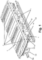
- Fig. 1 shows a detail of an arrangement of a consumer unit, here a distribution box, comprising at least one fastening strips 9, 9a fixed mounting rail 1, namely a DIN rail, for receiving switches and / or devices 2, a cover 3 for at least partially covering the support rail 1 and a holding device 4 for the cover 3.
- a distribution box comprising at least one fastening strips 9, 9a fixed mounting rail 1, namely a DIN rail, for receiving switches and / or devices 2, a cover 3 for at least partially covering the support rail 1 and a holding device 4 for the cover 3.
- the arrangement shown is intended to be arranged in a distribution box of the electrical installation, in particular in a distribution box for installation in a wall opening.
- a distribution box has a box bottom and vertically extending side walls from the edge of the box bottom. Both are not shown here for the sake of clarity.
- the arrangement shown has two mutually parallel spaced mounting strips 9, 9a, executed here in the form of a perforated strip.
- the at least one support rail 1 is by means of rail support 10 to the fixing strips 9, 9a attached.
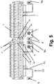
- a rail carrier 10 has, as in FIG. 5 can be seen, essentially a C-profile, the first short leg is attached to the mounting bar 9, here in the example by a screw fastening. On the second short leg, the support rail 1 is attached.
- the long, middle leg of the C-profile ensures that the mounting rail 1 is spaced from a plane spanned by the fastening strips 9, 9a level. If the fastening strips 9, 9a are attached to the floor of a distribution box, this thus causes free space to form between the support rail 1 and the floor of the distribution box. In this example, leads can be laid.
- the arrangement comprising the fastening strips 9, the mounting rails 1 fastened thereto and the cover fastened to the mounting rails 1 can also be used in consumer units of a different design, for example in a distribution box for surface mounting or in a free-standing distribution cabinet.
- FIG. 1 four mounting rails 1, shown here as four DIN rails shown, on which devices 2 are mounted.
- the devices 2 pass through the cover 3 at provided recesses.
- the cover 3 is preferably made of a plastic.
- the holding device 4 fixes the cover 3 in such a way that it can not fall down or be removed without loosening screws or other means.
- the cover 3 is fixed by means of the holding device 4 to the support rails 1 and is thus part of a unitary assembly that can be used in the distribution box as a whole.
- the holding device 4 is formed in two parts.
- the holding device 4 has a base part 4a and a holder 4b, wherein the holder 4b is at least partially removable from the base part 4a to provide a mounting space 7. The removal can be done without tools.
- Fig. 2 shows in the upper view the arrangement according to Fig. 1 without cover 3 and bottom right a detailed view of the base part 4a and the holder 4b.
- Fig. 3 shows the left arrangement with devices 2 without cover 3 and right a detail view of a holder 4b, which is mounted on a base part 4a.
- the base part 4a is laterally mounted on a rail 1, namely on the end of the rail 1, wherein the holder 4b is attached to the base part 4a.
- the rail 1 is designed as a DIN rail.
- the rail 1 is another rail 1 collinear aligned opposite, wherein between the rails 1, the base parts 4a and the holder 4b are arranged.
- Fig. 4 shows on the left the arrangement according to Fig. 3 and on the right a detailed view of a base part 4a, from which a holder 4b is removed.
- the base part 4a is assigned to the mounting rail 1, namely the DIN rail, and the holder 4b is removed from the base part 4a as a whole. So an assembly room 7 is created.
- Fig. 5 shows in a further view schematically an arrangement with on rails 1, namely DIN rails, mounted devices 2, wherein a holder 4b is mounted on a base part 4a and wherein the holder 4b is associated with a free area 5, from which it can be removed to a mounting space 7 to create.
- the free area 5 occupied by the holder 4b.
- the mounting rails 1 are attached to rail supports 10, and these are attached to mounting strips 9, 9a, screwed here.
- a base part 4a is attached and on each base part a holder 4b is attached.
- Each holder 4b is assigned to its free area 5 detachably.
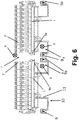
- Fig. 6 shows the arrangement according to Fig. 5 , wherein the holders 4b are removed and the respective free area 5 has become part of a relatively large mounting space 7 for lateral wiring.
- the relatively large mounting space 7 is provided for lateral wiring.
- cables 6, coming from above in the plane of the drawing can be inserted laterally under a DIN rail.
- the cables 6 can be inserted into a wiring area 8 under a DIN rail or under two DIN rails.
- the wiring region 8 is bounded laterally, in the area pointing away from the narrow end of the support rail 1, by the long leg 11 of the rail support 10.
- the rail supports 10 thus effectively form a cable channel for the cables or wires or cabling introduced through the mounting space 7 when the holders 4b are removed.
- Fig. 6 shows that the mounting space 7 allows a lateral penetration under two rails 1 in wiring areas 8.
- the mounting space 7 extends between two rails 1, wherein the ends of the rails 1 face the mounting space 7 and wherein the rails 1 are aligned with each other.
- the illustrated arrangement according to the invention can be advantageously used when two such arrangements are laterally juxtaposed in a larger distribution box to accommodate a larger number of devices 2 in the distribution box.
- the arrangement according to the invention then makes it possible, as in the FIG. 6 to see that even in the area between the two juxtaposed arrangements in a simple manner, a wiring or a laying of cables is possible.
- ⁇ U> REFERENCE LIST ⁇ / u> 1 DIN rail, DIN rail 2 device 3 cover 4 holder 4a Base part of 4 4b Holder of 4 5 outdoor Space 6 electric wire 7 mounting space 8th Wiring area under 1 9, 9a mounting strip 10 rail support 11 Long thigh
Landscapes
- Engineering & Computer Science (AREA)
- Power Engineering (AREA)
- Insertion, Bundling And Securing Of Wires For Electric Apparatuses (AREA)
- Installation Of Indoor Wiring (AREA)
- Distribution Board (AREA)
Abstract
Description
- Die Erfindung betrifft eine Anordnung, umfassend mindestens eine Tragschiene zur Aufnahme von Schaltern und/ oder Geräten, eine Abdeckung zur zumindest abschnittsweisen Bedeckung der Tragschiene und eine Halteeinrichtung für die Abdeckung.
- Die Erfindung betrifft auch einen Verteilerkasten der Elektroinstallation mit einer Anordnung, umfassend mindestens eine Tragschiene zur Aufnahme von Schaltern und/ oder Geräten, eine Abdeckung zur zumindest abschnittsweisen Bedeckung der Schiene und eine Halteeinrichtung für die Abdeckung.
- Anordnungen der genannten Art finden beispielsweise in Verbrauchereinheiten Verwendung. Insbesondere finden sie Verwendung in einem Verteilerkasten der Elektroinstallation, und dabei vorzugsweise in einem Verteilerkasten zum Einbau in eine Wandöffnung.
- In einem solchen Verteilerkasten sind auf Tragschienen, beispielsweise Hutschienen, eine Vielzahl von Geräten oder Schaltern montiert, wobei die Trag- bzw. Hutschienen bevorzugt parallel angeordnet sind. Bei den Geräten handelt es sich beispielsweise um Leitungsschutzschalter, Fehlerstromschutzschalter, Schaltrelais, Zeitrelais oder andere bekannte Installationsgeräte zur Montage auf Tragschienen in Installationsverteilungen.
- Die Geräte oder Schalter müssen verdrahtet bzw. verkabelt werden. Die Kabel können in Verdrahtungsbereichen unter den Trag- bzw. Hutschienen verlaufen. Die Trag- bzw. Hutschienen und die Geräte oder Schalter sind durch eine Abdeckung vor ungewolltem Zugriff geschützt. Die Abdeckung wird dabei durch eine Halteeinrichtung gehalten.
- Die
DE 10 2016 124 609 A1 zeigt einen Verteilerkasten zum Einbau in eine Wandöffnung, mit einem Kastenboden und mit sich vom Rand des Kastenbodens aus senkrecht erstreckenden vertikalen Seitenwänden, wobei parallel zu jeweils einer der vertikalen Seitenwände eine Befestigungsleiste zur Befestigung wenigstens einer Trag- bzw. Hutschiene in einem Abstand zu der vertikalen Seitenwand angeordnet ist, wodurch zwischen der Trag- bzw. Hutschiene und der benachbarten Seitenwand ein parallel zur vertikalen Seitenwand verlaufender Verdrahtungskanal zur Führung von in den Verteilerkasten zu- und herausgeführten Kabeln gebildet ist. Die Halteeinrichtung zur Halterung der Abdeckung zur zumindest abschnittsweisen Bedeckung der Tragschiene ist bei bekannten Verteilerkästen meistens an den vertikalen Seitenwänden des Verteilerkastens befestigt. - Es sind auch bereits Halteeinrichtungen bekannt, welche in einem seitlichen Bereich zwischen einem Ende der Trag- bzw. Hutschiene und einer Gehäusewand, insbesondere einer vertikalen Seitenwand, einer Verbrauchereinheit bzw. eines Verteilerkastens montiert sind. Hierdurch wird jedoch wertvoller Montageraum, der bei der Verkabelungen benötigt wird, in ungünstiger Weise ausgefüllt bzw. blockiert.
- Der Erfindung liegt daher die Aufgabe zugrunde, eine Anordnung mit einer Abdeckung und Tragschienen anzugeben, bei welcher auf den Trag- bzw. Hutschienen montierte Schalter und/ Geräte möglichst problemlos mit Kabeln versehen werden können.
- Erfindungsgemäß wird die voranstehende Aufgabe durch eine Anordnung mit den Merkmalen des Patentanspruchs 1 gelöst. Danach ist die eingangs genannte Anordnung dadurch gekennzeichnet, dass die Halteeinrichtung zweiteilig ausgebildet ist und ein Basisteil und einen Halter aufweist, wobei der Halter zumindest teilweise vom Basisteil zur Schaffung eines Montageraums entfernbar ist.
- Erfindungsgemäß ist zunächst erkannt worden, dass in Anordnungen des Stands der Technik dringend benötigter Montageraum häufig in ungünstiger Weise blockiert ist. Darauf ist erkannt worden, dass die Halteeinrichtung einer Abdeckung Potential bietet, Montageraum bereit zu stellen. Schließlich ist erkannt worden, dass ein Halter, der von einem Basisteil reversibel zumindest abschnittsweise oder als Ganzes abgenommen werden kann, wertvollen Montageraum freigeben kann. Durch das Entfernen des Halters entsteht ein freier Bereich zur seitlich durchgeführten Verdrahtung von Geräten. Kabel können seitlich in Verdrahtungsbereiche eingeführt werden, die unter den Trag- bzw. Hutschienen liegen sollen.
- Vorteilhaft ist das Basisteil der Trag- bzw. Hutschiene zugeordnet, und der Halter ist vom Basisteil als Ganzes entfernbar. Hierdurch kann ein Montageraum freigegeben werden, indem der Halter entfernt wird. Der Halter liegt nicht mehr als störendes Element bei der Verdrahtung vor.
- Weiter vorteilhaft ist das Basisteil seitlich auf der Trag- bzw. Hutschiene und/ oder auf einem Ende der Trag- bzw. Hutschiene aufgesteckt, wobei der Halter auf das Basisteil aufgesteckt ist. Ein Aufstecken auf das Ende einer Trag- bzw. Hutschiene erlaubt eine rasche Montage und leichte Zugänglichkeit des Basisteils. Ein aufgesteckter Halter ist leicht von einem Basisteil, bevorzugt ohne Werkzeugeinsatz, abziehbar und wieder aufsteckbar.
- Das Abziehen des Halters vom Basisteil erfolgt bevorzugt im Wesentlichen in einer Richtung, die orthogonal zur Längserstreckung der Trag- bzw. Hutsutschiene orientiert ist, um nicht an Komponenten der Anordnung hängen zu bleiben.
- Vorteilhaft ist der Halter einem Freibereich abnehmbar zugeordnet. Sobald der Halter aus dem Freibereich entfernt ist, ist der Freibereich Teil eines Montageraums oder wird zum Montageraum, um Kabel seitlich in Verdrahtungsbereiche unter einer Hutschiene einzuführen. So kann eine Person leicht Verkabelungen bzw. Verdrahtungen vornehmen.
- Vorteilhaft ermöglicht der Montageraum einen seitlichen Durchgriff unter eine Schiene in einen Verdrahtungsbereich. So kann ein Kabel von oben, also von den Geräten oder Schaltern herkommend, seitlich unter eine Hutschiene geschoben werden.
- Weiter vorteilhaft erstreckt sich der Montageraum zwischen zwei Schienen, wobei die Enden der Schienen dem Montageraum zugewandt sind und/ oder wobei die Schienen miteinander fluchten. So kann ein Zwischenraum zwischen zwei Schienen erzeugt werden, durch den eine montierende Person hindurch greifen kann, um von der Seite kommend unter eine Hutschiene oder beide Hutschienen greifen zu können.
- Bevorzugt umfasst eine Verbrauchereinheit, insbesondere ein Verteilerkasten der Elektroinstallation, eine Anordnung der hier beschriebenen Art.
- In der Zeichnung zeigen
- Fig. 1
- eine perspektivische Ansicht einer Anordnung, umfassend eine Abdeckung und mehrere Trag- bzw. Hutschienen, welche unter der Abdeckung angeordnet sind, sowie ein Basisteil und einen Halter einer Halteeinrichtung,
- Fig. 2
- oben eine perspektivische Ansicht der Anordnung gemäß
Fig. 1 ohne Abdeckung und rechts eine Detailansicht des Basisteils und des Halters, - Fig. 3
- links eine perspektivische Ansicht einer Anordnung ohne Abdeckung und rechts eine Detailansicht eines Halters, der auf einem Basisteil aufgesteckt ist,
- Fig. 4
- links die Anordnung gemäß
Fig. 3 und rechts eine Detailansicht eines Basisteils, von dem ein Halter entfernt ist, so dass ein Montageraum geschaffen ist, - Fig. 5
- eine Ansicht einer Anordnung mit auf Trag- bzw. Hutschienen montierten Geräten in Blickrichtung orthogonal zur Längserstreckung der Hutschienen, wobei ein Halter auf ein Basisteil aufgesteckt ist und wobei der Halter einem Freibereich zugeordnet ist, aus dem er entnehmbar ist, um einen Montageraum zu schaffen, und
- Fig. 6
- die Anordnung gemäß
Fig. 5 , wobei der Halter entfernt ist und der Freibereich Teil eines Montageraums zur seitlichen Verdrahtung geworden ist. -
Fig. 1 zeigt ausschnittsweise eine Anordnung einer Verbrauchereinheit, hier eines Verteilerkastens, umfassend mindestens eine an Befestigungsleisten 9, 9a befestigte Tragschiene 1, nämlich eine Hutschiene, zur Aufnahme von Schaltern und/ oder Geräten 2, eine Abdeckung 3 zur zumindest abschnittsweisen Bedeckung der Tragschiene 1 und eine Halteeinrichtung 4 für die Abdeckung 3. - Die dargestellte Anordnung ist dazu vorgesehen, um in einem Verteilerkasten der Elektroinstallation angeordnet zu sein, insbesondere in einem Verteilerkasten zum Einbau in eine Wandöffnung. Ein solcher Verteilerkasten hat einen Kastenboden und sich vom Rand des Kastenbodens aus senkrecht erstreckende Seitenwände. Beides ist hier der Übersichtlichkeit halber nicht dargestellt. Die dargestellt Anordnung besitzt zwei parallel zueinander in einem Abstand angeordnete Befestigungsleisten 9, 9a, hier in Form einer Lochleiste ausgeführt.
- Die wenigstens eine Tragschiene 1 ist mittels Schienenträger 10 an den Befestigungsleisten 9, 9a befestigt. Ein Schienenträger 10 hat, wie beispielsweise in
Figur 5 zu erkennen ist, im Wesentlichen ein C-Profil, dessen erster kurzer Schenkel an der Befestigungsleiste 9 befestigt ist, hier im Beispiel durch eine Schraubbefestigung. An dem zweiten kurzen Schenkel ist die Tragschiene 1 befestigt. Der lange, mittlere Schenkel des C-Profils sorgt dafür, dass die Tragschiene 1 von einer durch die Befestigungsleisten 9, 9a aufgespannten Ebene beabstandet ist. Wenn die Befestigungsleisten 9, 9a am Boden einer Verteilerkastens angebracht sind, ist dadurch also bewirkt, dass zwischen der Tragschiene 1 und dem Boden des Verteilerkastens ein freier Raum entsteht. In diesem können beispielsweise Zuleitungen verlegt werden. - Die Anordnung, umfassend die Befestigungsleisten 9, die daran befestigten Tragschienen 1 und die an den Tragschienen 1 befestigte Abdeckung kann auch in anders ausgebildete Verbrauchereinheiten eingesetzt werden, beispielsweise in einen Verteilerkasten zur Aufputzmontage oder in einen frei stehenden Verteilerschrank.
- Konkret sind hier in
Figur 1 vier Tragschienen 1, hier als vier Hutschienen ausgebildet, gezeigt, auf denen Geräte 2 montiert sind. Die Geräte 2 durchgreifen die Abdeckung 3 an dafür vorgesehenen Ausnehmungen. Die Abdeckung 3 ist bevorzugt aus einem Kunststoff gefertigt. Die Halteeinrichtung 4 fixiert die Abdeckung 3 derart, dass diese nicht herabfallen oder ohne Lösen von Schrauben oder anderen Mitteln abgenommen werden kann. Die Abdeckung 3 ist mittels der Halteeinrichtung 4 an den Tragschienen 1 befestigt und ist damit Teil einer einheitlichen Baugruppe, die in den Verteilerkasten als Ganzes eingesetzt werden kann. - Die Halteeinrichtung 4 ist zweiteilig ausgebildet. Die Halteeinrichtung 4 weist ein Basisteil 4a und einen Halter 4b auf, wobei der Halter 4b zumindest teilweise vom Basisteil 4a zur Schaffung eines Montageraums 7 entfernbar ist. Das Entfernen kann ohne Werkzeugeinsatz erfolgen.
-
Fig. 2 zeigt in der oberen Ansicht die Anordnung gemäßFig. 1 ohne Abdeckung 3 und rechts unten eine Detailansicht des Basisteils 4a und des Halters 4b. -
Fig. 3 zeigt links die Anordnung mit Geräten 2 ohne Abdeckung 3 und rechts eine Detailansicht eines Halters 4b, der auf einem Basisteil 4a aufgesteckt ist. Das Basisteil 4a ist seitlich auf einer Schiene 1, nämlich auf dem Ende der Schiene 1 aufgesteckt, wobei der Halter 4b auf das Basisteil 4a aufgesteckt ist. Die Schiene 1 ist als Hutschiene ausgestaltet. Der Schiene 1 liegt eine weitere Schiene 1 kollinear fluchtend gegenüber, wobei zwischen den Schienen 1 die Basisteile 4a und die Halter 4b angeordnet sind. -
Fig. 4 zeigt links die Anordnung gemäßFig. 3 und rechts eine Detailansicht eines Basisteils 4a, von dem ein Halter 4b entfernt ist. Das Basisteil 4a ist der Tragschiene 1, nämlich der Hutschiene, zugeordnet und der Halter 4b ist vom Basisteil 4a als Ganzes entfernt. So ist ein Montageraum 7 geschaffen. -
Fig. 5 zeigt in einer weiteren Ansicht schematisch eine Anordnung mit auf Tragschienen 1, nämlich Hutschienen, montierten Geräten 2, wobei ein Halter 4b auf ein Basisteil 4a aufgesteckt ist und wobei der Halter 4b einem Freibereich 5 zugeordnet ist, aus dem er entnehmbar ist, um einen Montageraum 7 zu schaffen. In der Konfiguration wie inFigur 5 dargestellt ist der Freibereich 5 mit dem Halter 4b belegt. Wenn der Halter 4b von dem Basisteil 4a entfernt wird, dann wird der Freibereich 5 frei und es kann in der dann entstehenden Verdrahtungs-Konfiguration durch den Freibereich 5 eine seitliche Verdrahtung vorgenommen werden, sieheFigur 6 . Die Tragschienen 1 sind an Schienenträgern 10 befestigt, und diese sind an Befestigungsleisten 9, 9a befestigt, hier angeschraubt. - Konkret sind zwei miteinander fluchtende und kollinear angeordnete Hutschienen gezeigt, deren Enden sich gegenüberliegen. Auf jedem Ende ist ein Basisteil 4a aufgesteckt und auf jedem Basisteil ist ein Halter 4b aufgesteckt. Jeder Halter 4b ist seinem Freibereich 5 abnehmbar zugeordnet.
-
Fig. 6 zeigt die Anordnung gemäßFig. 5 , wobei die Halter 4b entfernt sind und der jeweilige Freibereich 5 Teil eines relativ großen Montageraums 7 zur seitlichen Verdrahtung geworden ist. - Es sind schematisch Kabel 6 dargestellt. Der relativ große Montageraum 7 ist zur seitlichen Verdrahtung vorgesehen. Bei entferntem Halter 4b bzw. bei entfernten Haltern 4b können hier Kabel 6, in der Zeichenebene von oben kommend, unter einer Hutschiene seitlich eingeführt werden. Die Kabel 6 können in einen Verdrahtungsbereich 8 unter einer Hutschiene bzw. unter zwei Hutschienen eingeführt werden. Der Verdrahtungsbereich 8 wird dabei seitlich, in dem von dem schmalen Ende der Tragschiene 1 weg weisenden Bereich, von dem langen Schenkel 11 des Schienenträgers 10 begrenzt. Die Schienenträger 10 bilden somit gewissermaßen einen Kabelkanal für die durch den Montageraum 7 bei abgenommenen Haltern 4b eingeführten Kabel bzw. Drähte bzw. Verkabelungen.
-
Fig. 6 zeigt, dass der Montageraum 7 einen seitlichen Durchgriff unter zwei Schienen 1 in Verdrahtungsbereiche 8 ermöglicht. Der Montageraum 7 erstreckt sich zwischen zwei Schienen 1, wobei die Enden der Schienen 1 dem Montageraum 7 zugewandt sind und wobei die Schienen 1 miteinander fluchten. - Die dargestellte erfindungsgemäße Anordnung kann in vorteilhafter Weise dazu verwendet werden, wenn in einen größeren Verteilerkasten zwei solcher Anordnungen seitlich aneinander gereiht eingesetzt werden, um eine größere Anzahl von Geräten 2 in dem Verteilerkasten unterzubringen. Die erfindungsgemäße Anordnung ermöglicht es dann, wie in der
Figur 6 zu sehen, dass auch im Bereich zwischen den beiden aneinander gereihten Anordnungen auf einfach Art und Weise eine Verdrahtung oder eine Verlegung von Kabeln ermöglicht ist.Bezugszeichenliste 1 Tragschiene, Hutschiene 2 Gerät 3 Abdeckung 4 Halteeinrichtung 4a Basisteil von 4 4b Halter von 4 5 Freibereich 6 Kabel 7 Montageraum 8 Verdrahtungsbereich unter 1 9, 9a Befestigungsleiste 10 Schienenträger 11 Langer Schenkel
Claims (9)
- Anordnung, umfassend mindestens eine Tragschiene (1) zur Aufnahme von Schaltern und/ oder Geräten (2), eine Abdeckung (3) zur zumindest abschnittsweisen Bedeckung der Tragschiene (1) und eine Halteeinrichtung (4) für die Abdeckung (3),
dadurch gekennzeichnet, dass die Halteeinrichtung (4) zweiteilig ausgebildet ist und ein Basisteil (4a) und einen Halter (4b) für die Abdeckung (3) aufweist, wobei der Halter (4b) zumindest teilweise vom Basisteil (4a) zur Schaffung eines Montageraums (7) entfernbar ist. - Anordnung nach Anspruch 1, dadurch gekennzeichnet, dass das Basisteil (4a) der Tragschiene (1) zugeordnet ist und der Halter (4b) vom Basisteil (4a) als Ganzes entfernbar ist.
- Anordnung nach Anspruch 1 oder 2, dadurch gekennzeichnet, dass das Basisteil (4a) seitlich auf der Tragschiene (1) und/ oder auf einem Ende der Tragschiene (1) aufgesteckt ist, wobei der Halter (4b) auf das Basisteil (4a) aufgesteckt ist.
- Anordnung nach einem der voranstehenden Ansprüche, dadurch gekennzeichnet, dass der Halter (4b) einem Freibereich (5) abnehmbar zugeordnet ist.
- Anordnung nach einem der voranstehenden Ansprüche, dadurch gekennzeichnet, dass der Montageraum (7) einen seitlichen Durchgriff unter eine Schiene (1) in einen Verdrahtungsbereich (8) ermöglicht.
- Anordnung nach einem der voranstehenden Ansprüche, dadurch gekennzeichnet, dass der Montageraum (7) sich zwischen zwei Schienen (1) erstreckt, wobei die Enden der Schienen (1) dem Montageraum (7) zugewandt sind und/ oder wobei die Schienen (1) miteinander fluchten.
- Anordnung nach einem der vorigen Ansprüche, dadurch gekennzeichnet, dass die Anordnung zwei Befestigungsleisten (9, 9a) umfasst, und Schienenträger (10), wobei die wenigstens eine Tragschiene (1) mittels der Schienenträger (10) an den Befestigungsleisten (9, 9a) befestigt ist.
- Anordnung nach Anspruch 7, dadurch gekennzeichnet, dass der Schienenträger (10) ein C-Profil aufweist, dessen erster kurzer Schenkel an der Befestigungsleiste (9) befestigt ist, an dessen zweitem kurzen Schenkel die Tragschiene (1) befestigt ist, und dessen mittlerer Schenkel eine Beabstandung der Tragschiene (1) von einer durch die Befestigungsleisten (9, 9a) aufgespannten Ebene bewirkt.
- Verteilerkasten der Elektroinstallation, umfassend eine Anordnung nach einem der voranstehenden Ansprüche.
Applications Claiming Priority (1)
| Application Number | Priority Date | Filing Date | Title |
|---|---|---|---|
| DE102017130232.8A DE102017130232A1 (de) | 2017-12-15 | 2017-12-15 | Anordnung, umfassend eine Schiene und eine Abdeckung |
Publications (2)
| Publication Number | Publication Date |
|---|---|
| EP3499660A1 true EP3499660A1 (de) | 2019-06-19 |
| EP3499660B1 EP3499660B1 (de) | 2021-09-01 |
Family
ID=64362414
Family Applications (1)
| Application Number | Title | Priority Date | Filing Date |
|---|---|---|---|
| EP18206992.2A Active EP3499660B1 (de) | 2017-12-15 | 2018-11-19 | Anordnung, die eine erste und eine zweite tragschiene, eine abdeckung und eine erste und eine zweite halteeinrichtung umfasst, sowie verteilerkasten |
Country Status (3)
| Country | Link |
|---|---|
| EP (1) | EP3499660B1 (de) |
| DE (1) | DE102017130232A1 (de) |
| PT (1) | PT3499660T (de) |
Citations (10)
| Publication number | Priority date | Publication date | Assignee | Title |
|---|---|---|---|---|
| FR2308277A1 (fr) * | 1975-04-14 | 1976-11-12 | Merlin Gerin | Dispositif de fixation du capot d'un coffret electrique |
| EP0028553A1 (de) * | 1979-11-06 | 1981-05-13 | Merlin Gerin | Niederspannungsverteilerkasten mit Erhöhungssockel |
| EP0123788A2 (de) * | 1983-02-04 | 1984-11-07 | Gustav Hensel KG | Elektrisches Installationsgerät |
| FR2634326A1 (fr) * | 1988-07-12 | 1990-01-19 | Nozick Jacques | Coffret de repartition |
| US5683005A (en) * | 1996-02-27 | 1997-11-04 | Federal-Hoffman, Inc. | Adjustable mounting system |
| US6246004B1 (en) * | 1997-03-27 | 2001-06-12 | Gino Faccin | Electrical wiring frame |
| WO2004109883A1 (de) * | 2003-06-07 | 2004-12-16 | Hager Electro Gmbh | Kleinverteiler |
| EP1744427A1 (de) * | 2005-07-12 | 2007-01-17 | Legrand France | Gehäuse eines elektrischen Gerätes mit verstellbarer Tiefe |
| FR2956257A1 (fr) * | 2010-02-09 | 2011-08-12 | Legrand France | Organe de pre-assemblage d'un chassis d'appareil electrique sur une goulotte electrique, appareil electrique comportant un tel organe de pre -assemblage, et procede de fixation d'un tel organe de pre-assemblage sur le chassis d'un tel appareil electrique |
| DE102016124609A1 (de) | 2016-12-16 | 2018-06-21 | Abb Schweiz Ag | Verteilerkasten zum Einbau in eine Wandöffnung |
-
2017
- 2017-12-15 DE DE102017130232.8A patent/DE102017130232A1/de not_active Withdrawn
-
2018
- 2018-11-19 EP EP18206992.2A patent/EP3499660B1/de active Active
- 2018-11-19 PT PT18206992T patent/PT3499660T/pt unknown
Patent Citations (10)
| Publication number | Priority date | Publication date | Assignee | Title |
|---|---|---|---|---|
| FR2308277A1 (fr) * | 1975-04-14 | 1976-11-12 | Merlin Gerin | Dispositif de fixation du capot d'un coffret electrique |
| EP0028553A1 (de) * | 1979-11-06 | 1981-05-13 | Merlin Gerin | Niederspannungsverteilerkasten mit Erhöhungssockel |
| EP0123788A2 (de) * | 1983-02-04 | 1984-11-07 | Gustav Hensel KG | Elektrisches Installationsgerät |
| FR2634326A1 (fr) * | 1988-07-12 | 1990-01-19 | Nozick Jacques | Coffret de repartition |
| US5683005A (en) * | 1996-02-27 | 1997-11-04 | Federal-Hoffman, Inc. | Adjustable mounting system |
| US6246004B1 (en) * | 1997-03-27 | 2001-06-12 | Gino Faccin | Electrical wiring frame |
| WO2004109883A1 (de) * | 2003-06-07 | 2004-12-16 | Hager Electro Gmbh | Kleinverteiler |
| EP1744427A1 (de) * | 2005-07-12 | 2007-01-17 | Legrand France | Gehäuse eines elektrischen Gerätes mit verstellbarer Tiefe |
| FR2956257A1 (fr) * | 2010-02-09 | 2011-08-12 | Legrand France | Organe de pre-assemblage d'un chassis d'appareil electrique sur une goulotte electrique, appareil electrique comportant un tel organe de pre -assemblage, et procede de fixation d'un tel organe de pre-assemblage sur le chassis d'un tel appareil electrique |
| DE102016124609A1 (de) | 2016-12-16 | 2018-06-21 | Abb Schweiz Ag | Verteilerkasten zum Einbau in eine Wandöffnung |
Also Published As
| Publication number | Publication date |
|---|---|
| PT3499660T (pt) | 2021-10-25 |
| EP3499660B1 (de) | 2021-09-01 |
| DE102017130232A1 (de) | 2019-06-19 |
Similar Documents
| Publication | Publication Date | Title |
|---|---|---|
| EP3117112B1 (de) | Befestigungssystem zum montieren von geräten, insbesondere elektrogeräten | |
| EP1226639B1 (de) | Stromschienenanordung für ein elektrisches schaltfeld | |
| EP2171817B1 (de) | Vorrichtung zum anordnen und befestigen von elektrischen einheiten insbesondere in einem schaltschrank, sowie ein montagesystem mit einer solchen vorrichtung | |
| EP3906599B1 (de) | Kabelrinne mit einem schutzleiterhalter | |
| DE10007470C2 (de) | Schaltschrank | |
| DE102014115986A1 (de) | Vorrichtung zur Stromversorgung von an einem Regal anzuordnenden Stromverbrauchern | |
| EP3461376A1 (de) | Einrichtung zur warenpräsentation und adapter für eine solche einrichtung | |
| DE102005043878A1 (de) | Stromschienenanschlussmodul | |
| DE102018121744A1 (de) | Regalsystem mit elektrifiziertem Boden | |
| DE102016124609A1 (de) | Verteilerkasten zum Einbau in eine Wandöffnung | |
| EP2381549A1 (de) | Kabelführungsvorrichtung und Kabelrinne | |
| EP3499660B1 (de) | Anordnung, die eine erste und eine zweite tragschiene, eine abdeckung und eine erste und eine zweite halteeinrichtung umfasst, sowie verteilerkasten | |
| WO2007134559A1 (de) | Kabelhalter und anordnung mit einem kabelhalter | |
| DE102019108788A1 (de) | Umlenkvorrichtung | |
| CH648174A5 (en) | Wiring frame with U-shaped assembly hoop | |
| DE19713948C2 (de) | Innenausbau für Schaltschränke | |
| DE102006015317A1 (de) | Geräteeinbausatz zur Anordnung eines Gerätes in einer elektrischen Schaltanlage | |
| EP3965240A1 (de) | Vorrichtung zur befestigung und verdrahtung von elektrischen einheiten in einem schaltschrank | |
| DE69619021T2 (de) | Gehäuse eines elektrischen Gerätes | |
| WO1990005400A1 (de) | Vorrichtung zum führen und festhalten von leitungen, schläuchen und dgl. in schaltschränken | |
| DE102019119116A1 (de) | Anordnung zur verteilung von gasförmigen und flüssigen medien in einem labor | |
| DE2812089C2 (de) | Schraub- und lotbare Befestigungsvorrichtung fur elektrische Leiter | |
| DE19739610C1 (de) | Elektro-Verteiler für Wohnungen und Gewerbe mit einer Profilschiene | |
| DE1465555A1 (de) | Stromverteilungstafel | |
| DE2418028A1 (de) | Anschlussvorrichtung fuer elektrische verteilerkaesten |
Legal Events
| Date | Code | Title | Description |
|---|---|---|---|
| PUAI | Public reference made under article 153(3) epc to a published international application that has entered the european phase |
Free format text: ORIGINAL CODE: 0009012 |
|
| STAA | Information on the status of an ep patent application or granted ep patent |
Free format text: STATUS: THE APPLICATION HAS BEEN PUBLISHED |
|
| AK | Designated contracting states |
Kind code of ref document: A1 Designated state(s): AL AT BE BG CH CY CZ DE DK EE ES FI FR GB GR HR HU IE IS IT LI LT LU LV MC MK MT NL NO PL PT RO RS SE SI SK SM TR |
|
| AX | Request for extension of the european patent |
Extension state: BA ME |
|
| STAA | Information on the status of an ep patent application or granted ep patent |
Free format text: STATUS: REQUEST FOR EXAMINATION WAS MADE |
|
| 17P | Request for examination filed |
Effective date: 20191202 |
|
| RBV | Designated contracting states (corrected) |
Designated state(s): AL AT BE BG CH CY CZ DE DK EE ES FI FR GB GR HR HU IE IS IT LI LT LU LV MC MK MT NL NO PL PT RO RS SE SI SK SM TR |
|
| STAA | Information on the status of an ep patent application or granted ep patent |
Free format text: STATUS: EXAMINATION IS IN PROGRESS |
|
| 17Q | First examination report despatched |
Effective date: 20200422 |
|
| GRAP | Despatch of communication of intention to grant a patent |
Free format text: ORIGINAL CODE: EPIDOSNIGR1 |
|
| STAA | Information on the status of an ep patent application or granted ep patent |
Free format text: STATUS: GRANT OF PATENT IS INTENDED |
|
| RIC1 | Information provided on ipc code assigned before grant |
Ipc: H02B 1/42 20060101ALI20210316BHEP Ipc: H02B 1/20 20060101ALI20210316BHEP Ipc: H02B 1/06 20060101ALI20210316BHEP Ipc: H02B 1/052 20060101ALI20210316BHEP Ipc: H02B 1/44 20060101AFI20210316BHEP |
|
| INTG | Intention to grant announced |
Effective date: 20210414 |
|
| GRAJ | Information related to disapproval of communication of intention to grant by the applicant or resumption of examination proceedings by the epo deleted |
Free format text: ORIGINAL CODE: EPIDOSDIGR1 |
|
| STAA | Information on the status of an ep patent application or granted ep patent |
Free format text: STATUS: EXAMINATION IS IN PROGRESS |
|
| GRAP | Despatch of communication of intention to grant a patent |
Free format text: ORIGINAL CODE: EPIDOSNIGR1 |
|
| INTC | Intention to grant announced (deleted) | ||
| RAP3 | Party data changed (applicant data changed or rights of an application transferred) |
Owner name: ABB SCHWEIZ AG |
|
| STAA | Information on the status of an ep patent application or granted ep patent |
Free format text: STATUS: GRANT OF PATENT IS INTENDED |
|
| GRAJ | Information related to disapproval of communication of intention to grant by the applicant or resumption of examination proceedings by the epo deleted |
Free format text: ORIGINAL CODE: EPIDOSDIGR1 |
|
| GRAP | Despatch of communication of intention to grant a patent |
Free format text: ORIGINAL CODE: EPIDOSNIGR1 |
|
| STAA | Information on the status of an ep patent application or granted ep patent |
Free format text: STATUS: EXAMINATION IS IN PROGRESS |
|
| GRAJ | Information related to disapproval of communication of intention to grant by the applicant or resumption of examination proceedings by the epo deleted |
Free format text: ORIGINAL CODE: EPIDOSDIGR1 |
|
| GRAP | Despatch of communication of intention to grant a patent |
Free format text: ORIGINAL CODE: EPIDOSNIGR1 |
|
| STAA | Information on the status of an ep patent application or granted ep patent |
Free format text: STATUS: GRANT OF PATENT IS INTENDED |
|
| GRAS | Grant fee paid |
Free format text: ORIGINAL CODE: EPIDOSNIGR3 |
|
| INTG | Intention to grant announced |
Effective date: 20210624 |
|
| GRAA | (expected) grant |
Free format text: ORIGINAL CODE: 0009210 |
|
| STAA | Information on the status of an ep patent application or granted ep patent |
Free format text: STATUS: THE PATENT HAS BEEN GRANTED |
|
| INTC | Intention to grant announced (deleted) | ||
| INTG | Intention to grant announced |
Effective date: 20210716 |
|
| AK | Designated contracting states |
Kind code of ref document: B1 Designated state(s): AL AT BE BG CH CY CZ DE DK EE ES FI FR GB GR HR HU IE IS IT LI LT LU LV MC MK MT NL NO PL PT RO RS SE SI SK SM TR |
|
| REG | Reference to a national code |
Ref country code: GB Ref legal event code: FG4D Free format text: NOT ENGLISH |
|
| REG | Reference to a national code |
Ref country code: CH Ref legal event code: EP Ref country code: AT Ref legal event code: REF Ref document number: 1427213 Country of ref document: AT Kind code of ref document: T Effective date: 20210915 |
|
| REG | Reference to a national code |
Ref country code: DE Ref legal event code: R096 Ref document number: 502018006812 Country of ref document: DE |
|
| REG | Reference to a national code |
Ref country code: IE Ref legal event code: FG4D Free format text: LANGUAGE OF EP DOCUMENT: GERMAN |
|
| REG | Reference to a national code |
Ref country code: PT Ref legal event code: SC4A Ref document number: 3499660 Country of ref document: PT Date of ref document: 20211025 Kind code of ref document: T Free format text: AVAILABILITY OF NATIONAL TRANSLATION Effective date: 20211018 |
|
| REG | Reference to a national code |
Ref country code: LT Ref legal event code: MG9D |
|
| REG | Reference to a national code |
Ref country code: NL Ref legal event code: MP Effective date: 20210901 |
|
| PG25 | Lapsed in a contracting state [announced via postgrant information from national office to epo] |
Ref country code: NO Free format text: LAPSE BECAUSE OF FAILURE TO SUBMIT A TRANSLATION OF THE DESCRIPTION OR TO PAY THE FEE WITHIN THE PRESCRIBED TIME-LIMIT Effective date: 20211201 Ref country code: BG Free format text: LAPSE BECAUSE OF FAILURE TO SUBMIT A TRANSLATION OF THE DESCRIPTION OR TO PAY THE FEE WITHIN THE PRESCRIBED TIME-LIMIT Effective date: 20211201 Ref country code: LT Free format text: LAPSE BECAUSE OF FAILURE TO SUBMIT A TRANSLATION OF THE DESCRIPTION OR TO PAY THE FEE WITHIN THE PRESCRIBED TIME-LIMIT Effective date: 20210901 Ref country code: SE Free format text: LAPSE BECAUSE OF FAILURE TO SUBMIT A TRANSLATION OF THE DESCRIPTION OR TO PAY THE FEE WITHIN THE PRESCRIBED TIME-LIMIT Effective date: 20210901 Ref country code: RS Free format text: LAPSE BECAUSE OF FAILURE TO SUBMIT A TRANSLATION OF THE DESCRIPTION OR TO PAY THE FEE WITHIN THE PRESCRIBED TIME-LIMIT Effective date: 20210901 Ref country code: FI Free format text: LAPSE BECAUSE OF FAILURE TO SUBMIT A TRANSLATION OF THE DESCRIPTION OR TO PAY THE FEE WITHIN THE PRESCRIBED TIME-LIMIT Effective date: 20210901 Ref country code: ES Free format text: LAPSE BECAUSE OF FAILURE TO SUBMIT A TRANSLATION OF THE DESCRIPTION OR TO PAY THE FEE WITHIN THE PRESCRIBED TIME-LIMIT Effective date: 20210901 Ref country code: HR Free format text: LAPSE BECAUSE OF FAILURE TO SUBMIT A TRANSLATION OF THE DESCRIPTION OR TO PAY THE FEE WITHIN THE PRESCRIBED TIME-LIMIT Effective date: 20210901 |
|
| PG25 | Lapsed in a contracting state [announced via postgrant information from national office to epo] |
Ref country code: PL Free format text: LAPSE BECAUSE OF FAILURE TO SUBMIT A TRANSLATION OF THE DESCRIPTION OR TO PAY THE FEE WITHIN THE PRESCRIBED TIME-LIMIT Effective date: 20210901 Ref country code: LV Free format text: LAPSE BECAUSE OF FAILURE TO SUBMIT A TRANSLATION OF THE DESCRIPTION OR TO PAY THE FEE WITHIN THE PRESCRIBED TIME-LIMIT Effective date: 20210901 Ref country code: GR Free format text: LAPSE BECAUSE OF FAILURE TO SUBMIT A TRANSLATION OF THE DESCRIPTION OR TO PAY THE FEE WITHIN THE PRESCRIBED TIME-LIMIT Effective date: 20211202 |
|
| PG25 | Lapsed in a contracting state [announced via postgrant information from national office to epo] |
Ref country code: IS Free format text: LAPSE BECAUSE OF FAILURE TO SUBMIT A TRANSLATION OF THE DESCRIPTION OR TO PAY THE FEE WITHIN THE PRESCRIBED TIME-LIMIT Effective date: 20220101 Ref country code: SM Free format text: LAPSE BECAUSE OF FAILURE TO SUBMIT A TRANSLATION OF THE DESCRIPTION OR TO PAY THE FEE WITHIN THE PRESCRIBED TIME-LIMIT Effective date: 20210901 Ref country code: SK Free format text: LAPSE BECAUSE OF FAILURE TO SUBMIT A TRANSLATION OF THE DESCRIPTION OR TO PAY THE FEE WITHIN THE PRESCRIBED TIME-LIMIT Effective date: 20210901 Ref country code: RO Free format text: LAPSE BECAUSE OF FAILURE TO SUBMIT A TRANSLATION OF THE DESCRIPTION OR TO PAY THE FEE WITHIN THE PRESCRIBED TIME-LIMIT Effective date: 20210901 Ref country code: NL Free format text: LAPSE BECAUSE OF FAILURE TO SUBMIT A TRANSLATION OF THE DESCRIPTION OR TO PAY THE FEE WITHIN THE PRESCRIBED TIME-LIMIT Effective date: 20210901 Ref country code: EE Free format text: LAPSE BECAUSE OF FAILURE TO SUBMIT A TRANSLATION OF THE DESCRIPTION OR TO PAY THE FEE WITHIN THE PRESCRIBED TIME-LIMIT Effective date: 20210901 Ref country code: CZ Free format text: LAPSE BECAUSE OF FAILURE TO SUBMIT A TRANSLATION OF THE DESCRIPTION OR TO PAY THE FEE WITHIN THE PRESCRIBED TIME-LIMIT Effective date: 20210901 Ref country code: AL Free format text: LAPSE BECAUSE OF FAILURE TO SUBMIT A TRANSLATION OF THE DESCRIPTION OR TO PAY THE FEE WITHIN THE PRESCRIBED TIME-LIMIT Effective date: 20210901 |
|
| REG | Reference to a national code |
Ref country code: DE Ref legal event code: R097 Ref document number: 502018006812 Country of ref document: DE |
|
| PG25 | Lapsed in a contracting state [announced via postgrant information from national office to epo] |
Ref country code: MC Free format text: LAPSE BECAUSE OF FAILURE TO SUBMIT A TRANSLATION OF THE DESCRIPTION OR TO PAY THE FEE WITHIN THE PRESCRIBED TIME-LIMIT Effective date: 20210901 |
|
| REG | Reference to a national code |
Ref country code: CH Ref legal event code: PL |
|
| PLBE | No opposition filed within time limit |
Free format text: ORIGINAL CODE: 0009261 |
|
| STAA | Information on the status of an ep patent application or granted ep patent |
Free format text: STATUS: NO OPPOSITION FILED WITHIN TIME LIMIT |
|
| PG25 | Lapsed in a contracting state [announced via postgrant information from national office to epo] |
Ref country code: LU Free format text: LAPSE BECAUSE OF NON-PAYMENT OF DUE FEES Effective date: 20211119 Ref country code: IT Free format text: LAPSE BECAUSE OF FAILURE TO SUBMIT A TRANSLATION OF THE DESCRIPTION OR TO PAY THE FEE WITHIN THE PRESCRIBED TIME-LIMIT Effective date: 20210901 Ref country code: DK Free format text: LAPSE BECAUSE OF FAILURE TO SUBMIT A TRANSLATION OF THE DESCRIPTION OR TO PAY THE FEE WITHIN THE PRESCRIBED TIME-LIMIT Effective date: 20210901 Ref country code: BE Free format text: LAPSE BECAUSE OF NON-PAYMENT OF DUE FEES Effective date: 20211130 |
|
| REG | Reference to a national code |
Ref country code: BE Ref legal event code: MM Effective date: 20211130 |
|
| 26N | No opposition filed |
Effective date: 20220602 |
|
| PG25 | Lapsed in a contracting state [announced via postgrant information from national office to epo] |
Ref country code: SI Free format text: LAPSE BECAUSE OF FAILURE TO SUBMIT A TRANSLATION OF THE DESCRIPTION OR TO PAY THE FEE WITHIN THE PRESCRIBED TIME-LIMIT Effective date: 20210901 Ref country code: LI Free format text: LAPSE BECAUSE OF NON-PAYMENT OF DUE FEES Effective date: 20211130 Ref country code: CH Free format text: LAPSE BECAUSE OF NON-PAYMENT OF DUE FEES Effective date: 20211130 |
|
| PG25 | Lapsed in a contracting state [announced via postgrant information from national office to epo] |
Ref country code: IE Free format text: LAPSE BECAUSE OF NON-PAYMENT OF DUE FEES Effective date: 20211119 |
|
| PG25 | Lapsed in a contracting state [announced via postgrant information from national office to epo] |
Ref country code: FR Free format text: LAPSE BECAUSE OF NON-PAYMENT OF DUE FEES Effective date: 20211130 |
|
| PG25 | Lapsed in a contracting state [announced via postgrant information from national office to epo] |
Ref country code: CY Free format text: LAPSE BECAUSE OF FAILURE TO SUBMIT A TRANSLATION OF THE DESCRIPTION OR TO PAY THE FEE WITHIN THE PRESCRIBED TIME-LIMIT Effective date: 20210901 |
|
| GBPC | Gb: european patent ceased through non-payment of renewal fee |
Effective date: 20221119 |
|
| PG25 | Lapsed in a contracting state [announced via postgrant information from national office to epo] |
Ref country code: HU Free format text: LAPSE BECAUSE OF FAILURE TO SUBMIT A TRANSLATION OF THE DESCRIPTION OR TO PAY THE FEE WITHIN THE PRESCRIBED TIME-LIMIT; INVALID AB INITIO Effective date: 20181119 |
|
| PG25 | Lapsed in a contracting state [announced via postgrant information from national office to epo] |
Ref country code: GB Free format text: LAPSE BECAUSE OF NON-PAYMENT OF DUE FEES Effective date: 20221119 |
|
| PG25 | Lapsed in a contracting state [announced via postgrant information from national office to epo] |
Ref country code: MK Free format text: LAPSE BECAUSE OF FAILURE TO SUBMIT A TRANSLATION OF THE DESCRIPTION OR TO PAY THE FEE WITHIN THE PRESCRIBED TIME-LIMIT Effective date: 20210901 |
|
| PG25 | Lapsed in a contracting state [announced via postgrant information from national office to epo] |
Ref country code: MT Free format text: LAPSE BECAUSE OF FAILURE TO SUBMIT A TRANSLATION OF THE DESCRIPTION OR TO PAY THE FEE WITHIN THE PRESCRIBED TIME-LIMIT Effective date: 20210901 |
|
| REG | Reference to a national code |
Ref country code: AT Ref legal event code: MM01 Ref document number: 1427213 Country of ref document: AT Kind code of ref document: T Effective date: 20231119 |
|
| PG25 | Lapsed in a contracting state [announced via postgrant information from national office to epo] |
Ref country code: AT Free format text: LAPSE BECAUSE OF NON-PAYMENT OF DUE FEES Effective date: 20231119 |
|
| PG25 | Lapsed in a contracting state [announced via postgrant information from national office to epo] |
Ref country code: AT Free format text: LAPSE BECAUSE OF NON-PAYMENT OF DUE FEES Effective date: 20231119 |
|
| PGFP | Annual fee paid to national office [announced via postgrant information from national office to epo] |
Ref country code: PT Payment date: 20251106 Year of fee payment: 8 |
|
| PG25 | Lapsed in a contracting state [announced via postgrant information from national office to epo] |
Ref country code: TR Free format text: LAPSE BECAUSE OF FAILURE TO SUBMIT A TRANSLATION OF THE DESCRIPTION OR TO PAY THE FEE WITHIN THE PRESCRIBED TIME-LIMIT Effective date: 20210901 |
|
| PGFP | Annual fee paid to national office [announced via postgrant information from national office to epo] |
Ref country code: DE Payment date: 20251119 Year of fee payment: 8 |
|
| PGFP | Annual fee paid to national office [announced via postgrant information from national office to epo] |
Ref country code: AT Payment date: 20260410 Year of fee payment: 5 |