EP3499660B1 - Agencement comprenant un premier et un second rails support, un couvercle et un premier et un second dispositifs support, et boîtier de distribution - Google Patents
Agencement comprenant un premier et un second rails support, un couvercle et un premier et un second dispositifs support, et boîtier de distribution Download PDFInfo
- Publication number
- EP3499660B1 EP3499660B1 EP18206992.2A EP18206992A EP3499660B1 EP 3499660 B1 EP3499660 B1 EP 3499660B1 EP 18206992 A EP18206992 A EP 18206992A EP 3499660 B1 EP3499660 B1 EP 3499660B1
- Authority
- EP
- European Patent Office
- Prior art keywords
- support rail
- holder
- base part
- rail
- support
- Prior art date
- Legal status (The legal status is an assumption and is not a legal conclusion. Google has not performed a legal analysis and makes no representation as to the accuracy of the status listed.)
- Active
Links
Images


Classifications
-
- H—ELECTRICITY
- H02—GENERATION; CONVERSION OR DISTRIBUTION OF ELECTRIC POWER
- H02B—BOARDS, SUBSTATIONS OR SWITCHING ARRANGEMENTS FOR THE SUPPLY OR DISTRIBUTION OF ELECTRIC POWER
- H02B1/00—Frameworks, boards, panels, desks, casings; Details of substations or switching arrangements
- H02B1/015—Boards, panels, desks; Parts thereof or accessories therefor
- H02B1/06—Boards, panels, desks; Parts thereof or accessories therefor having associated enclosures, e.g. for preventing access to live parts
-
- H—ELECTRICITY
- H02—GENERATION; CONVERSION OR DISTRIBUTION OF ELECTRIC POWER
- H02B—BOARDS, SUBSTATIONS OR SWITCHING ARRANGEMENTS FOR THE SUPPLY OR DISTRIBUTION OF ELECTRIC POWER
- H02B1/00—Frameworks, boards, panels, desks, casings; Details of substations or switching arrangements
- H02B1/015—Boards, panels, desks; Parts thereof or accessories therefor
- H02B1/04—Mounting thereon of switches or of other devices in general, the switch or device having, or being without, casing
- H02B1/052—Mounting on rails
-
- H—ELECTRICITY
- H02—GENERATION; CONVERSION OR DISTRIBUTION OF ELECTRIC POWER
- H02B—BOARDS, SUBSTATIONS OR SWITCHING ARRANGEMENTS FOR THE SUPPLY OR DISTRIBUTION OF ELECTRIC POWER
- H02B1/00—Frameworks, boards, panels, desks, casings; Details of substations or switching arrangements
- H02B1/20—Bus-bar or other wiring layouts, e.g. in cubicles, in switchyards
- H02B1/202—Cable lay-outs
-
- H—ELECTRICITY
- H02—GENERATION; CONVERSION OR DISTRIBUTION OF ELECTRIC POWER
- H02B—BOARDS, SUBSTATIONS OR SWITCHING ARRANGEMENTS FOR THE SUPPLY OR DISTRIBUTION OF ELECTRIC POWER
- H02B1/00—Frameworks, boards, panels, desks, casings; Details of substations or switching arrangements
- H02B1/26—Casings; Parts thereof or accessories therefor
- H02B1/40—Wall-mounted casings; Parts thereof or accessories therefor
- H02B1/42—Mounting of devices therein
Definitions
- the invention relates to an arrangement according to the preamble of claim 1.
- An arrangement of this type is from the FR 2 634 326 A1 known, there is a removable holder designed as a side of a hood.
- the EP 1 744 427 A1 shows that support rails extend between two side wings that form a frame. From the EP 0 028 553 A1 it is known to pivot a plate away from a base.
- Arrangements of the type mentioned are used, for example, in consumer units.
- they are used in a distribution box for electrical installations, and preferably in a distribution box for installation in a wall opening.
- a large number of devices or switches are mounted on mounting rails, for example top hat rails, the mounting rails or top hat rails preferably being arranged in parallel.
- the devices are, for example, line circuit breakers, residual current circuit breakers, switching relays, timing relays or other known installation devices for mounting on mounting rails in installation distributions.
- the devices or switches must be wired or wired.
- the cables can run in wiring areas under the mounting rails or top hat rails.
- the mounting or top hat rails and the devices or switches are protected against unauthorized access by a cover. The cover is thereby through a Holding device held.
- the DE 10 2016 124 609 A1 shows a junction box for installation in a wall opening, with a box bottom and with vertical side walls extending vertically from the edge of the box bottom, with a fastening strip parallel to each of the vertical side walls for fastening at least one support or top hat rail at a distance from the vertical one Side wall is arranged, whereby between the support or top hat rail and the adjacent side wall, a wiring duct running parallel to the vertical side wall is formed for guiding cables fed into and out of the junction box.
- the holding device for holding the cover for at least partially covering the support rail is mostly attached to the vertical side walls of the junction box.
- the invention is therefore based on the object of specifying an arrangement with a cover and mounting rails, in which switches and / devices mounted on the mounting rails or top-hat rails can be provided with cables as easily as possible.
- the base part is assigned to the support or top-hat rail, and the holder can be removed as a whole from the base part. This enables a mounting space to be released by removing the holder.
- the holder is no longer a disruptive element in the wiring.
- the base part is placed on the side of the support or top hat rail and / or on one end of the support or top hat rail, the holder being pushed onto the base part. Plugging onto the end of a mounting or top hat rail allows quick assembly and easy access to the base part. An attached holder can easily be pulled off and re-attached from a base part, preferably without the use of tools.
- the retainer is preferably withdrawn from the base part essentially in a direction that is orthogonal to the longitudinal extension of the support or. DIN rail is oriented so as not to get caught on components of the arrangement.
- the holder is advantageously assigned to a free area such that it can be removed. As soon as the holder is removed from the free area, the free area is part of an assembly space or becomes an assembly space in order to introduce cables laterally into wiring areas under a top-hat rail. So one person can easily do cabling or wiring.
- the assembly space enables lateral access under a rail into a wiring area.
- a cable can be slid sideways under a top-hat rail from above, i.e. coming from the devices or switches.
- the assembly space extends between two rails, with the ends of the rails facing the assembly space and / or with the rails being aligned with one another. In this way, an intermediate space can be created between two rails, through which an assembling person can reach in order to be able to reach under a top-hat rail or both top-hat rails when coming from the side.
- a consumer unit in particular a distribution box for the electrical installation, preferably comprises an arrangement of the type described here.
- Fig. 1 shows a detail of an arrangement of a consumer unit, here a distribution box, comprising a mounting rail 1 attached to mounting strips 9, 9a, namely a top-hat rail, for receiving switches and / or devices 2, a cover 3 for at least partially covering the mounting rail 1 and a holding device 4 for the cover 3.
- a distribution box comprising a mounting rail 1 attached to mounting strips 9, 9a, namely a top-hat rail, for receiving switches and / or devices 2, a cover 3 for at least partially covering the mounting rail 1 and a holding device 4 for the cover 3.
- the arrangement shown is intended to be arranged in a junction box of the electrical installation, in particular in a junction box for installation in a wall opening.
- a junction box has a box bottom and side walls extending perpendicularly from the edge of the box bottom. For the sake of clarity, neither is shown here.
- the arrangement shown has two fastening strips 9, 9a arranged parallel to one another at a distance, here designed in the form of a perforated strip.
- the mounting rail 1 is attached to the fastening strips by means of rail supports 10 9, 9a attached.
- a rail support 10 has, as for example in FIG Figure 5 can be seen, essentially a C-profile, the first short leg of which is fastened to the fastening strip 9, here in the example by a screw fastening.
- the support rail 1 is attached to the second short leg.
- the long, middle leg of the C-profile ensures that the support rail 1 is spaced apart from a plane spanned by the fastening strips 9, 9a. If the fastening strips 9, 9a are attached to the bottom of a distribution box, this has the effect that a free space is created between the support rail 1 and the bottom of the distribution box. In this, for example, supply lines can be laid.
- the arrangement comprising the fastening strips 9, the mounting rails 1 attached to them and the cover attached to the mounting rails 1 can also be used in differently designed consumer units, for example in a distribution box for surface mounting or in a free-standing distribution cabinet.
- FIG. 1 For brevity, here in Figure 1 four mounting rails 1, designed here as four top-hat rails, are shown, on which devices 2 are mounted.
- the devices 2 reach through the cover 3 at recesses provided for this purpose.
- the cover 3 is preferably made of a plastic.
- the holding device 4 fixes the cover 3 in such a way that it cannot fall down or can be removed without loosening screws or other means.
- the cover 3 is fastened to the mounting rails 1 by means of the holding device 4 and is therefore part of a uniform assembly that can be inserted as a whole in the distribution box.
- the holding device 4 is designed in two parts.
- the holding device 4 has a base part 4a and a holder 4b, the holder 4b being at least partially removable from the base part 4a to create an assembly space 7. It can be removed without the use of tools.
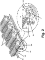
- Fig. 2 shows in the top view the arrangement according to Fig. 1 without cover 3 and at the bottom right a detailed view of the base part 4a and of the holder 4b.
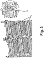
- Fig. 3 shows on the left the arrangement with devices 2 without cover 3 and on the right a detailed view of a holder 4b which is attached to a base part 4a.
- the base part 4a is placed laterally on a rail 1, namely on the end of the rail 1, the holder 4b being pushed onto the base part 4a.
- the rail 1 is designed as a top-hat rail.
- Another rail 1 lies collinearly in alignment with the rail 1 opposite, wherein the base parts 4a and the holder 4b are arranged between the rails 1.
- Fig. 4 shows on the left the arrangement according to Fig. 3 and on the right a detailed view of a base part 4a from which a holder 4b has been removed.
- the base part 4a is assigned to the support rail 1, namely the top-hat rail, and the holder 4b is removed as a whole from the base part 4a.
- An assembly space 7 is thus created.
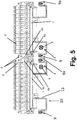
- Fig. 5 shows in a further view, schematically, an arrangement with devices 2 mounted on mounting rails 1, namely top-hat rails, with a holder 4b being attached to a base part 4a and with the holder 4b being assigned to a free area 5, from which it can be removed, around a mounting space 7 to create.
- the free area 5 is shown occupied by the holder 4b.
- the mounting rails 1 are fastened to rail supports 10, and these are fastened to fastening strips 9, 9a, here screwed on.
- top-hat rails that are aligned with one another and arranged collinearly are shown, the ends of which are opposite one another.
- a base part 4a is attached to each end and a holder 4b is attached to each base part.
- Each holder 4b is assigned to its free area 5 in a removable manner.
- Fig. 6 shows the arrangement according to Fig. 5 , wherein the holders 4b are removed and the respective free area 5 has become part of a relatively large assembly space 7 for lateral wiring.
- Cables 6 are shown schematically.
- the relatively large assembly space 7 is provided for wiring from the side.
- cables 6, coming from above in the plane of the drawing can be inserted laterally under a top-hat rail.
- the cables 6 can be introduced into a wiring area 8 under a top-hat rail or under two top-hat rails.
- the wiring area 8 is laterally bounded by the long leg 11 of the rail support 10 in the area facing away from the narrow end of the support rail 1.
- the rail supports 10 thus form, so to speak, a cable duct for the cables or wires or cabling introduced through the assembly space 7 with the holders 4b removed.
- Fig. 6 shows that the assembly space 7 enables lateral access under two rails 1 in wiring areas 8.
- the mounting space 7 extends between two rails 1, the ends of the rails 1 facing the mounting space 7 and the rails 1 being aligned with one another.
- two sets, each with a support rail and a holding device, are preferably used in a row side by side in order to accommodate a larger number of devices 2 in the distribution box. This makes it possible, as in Figure 6 it can be seen that wiring or the laying of cables is also possible in a simple manner in the area between two such sets.
Landscapes
- Engineering & Computer Science (AREA)
- Power Engineering (AREA)
- Installation Of Indoor Wiring (AREA)
- Distribution Board (AREA)
- Insertion, Bundling And Securing Of Wires For Electric Apparatuses (AREA)
Claims (6)
- Agencement, comportant- un premier rail de support (1) servant à la réception d'appareils (2),- un deuxième rail de support (1) servant à la réception d'appareils (2),- des zones de câblage (8) servant au câblage des appareils (2) étant situées en dessous des rails de support (1),- un couvercle (3) servant à recouvrir le rail de support (1) au moins dans certaines parties et- un premier dispositif de retenue (4) pour le couvercle (3), lequel se trouve à une extrémité du premier rail de support (1) et à l'aide duquel le couvercle (3) est fixé au premier rail de support (1),- le premier dispositif de retenue (4) étant réalisé en deux parties et comprenant une première partie de base (4a) et un premier support (4b) pour le couvercle (3),- le premier support (4b) pouvant être retiré au moins partiellement de la partie de base (4a) pour créer un espace de montage (7) entre les rails de support (1),- la première partie de base (4a) étant associée au premier rail de support (1), c'est-à-dire étant enfichée latéralement sur le premier rail de support (1) et/ou sur une extrémité du premier rail de support (1),- le premier support (4b) pouvant être retiré de la première partie de base (4a) comme un tout et le premier support (4b) étant enfiché sur la première partie de base (4a) ,- un deuxième dispositif de retenue (4), lequel se trouve à une extrémité du deuxième rail de support (1) et à l'aide duquel le couvercle (3) est fixé au deuxième rail de support (1),- le deuxième dispositif de retenue (4) étant réalisé en deux parties et comprenant une deuxième partie de base (4a) et un deuxième support (4b) pour le couvercle (3),- le deuxième support (4b) pouvant être retiré au moins partiellement de la deuxième partie de base (4a) pour créer un espace de montage (7) entre les rails de support (1),- la deuxième partie de base (4a) étant associée au deuxième rail de support (1), c'est-à-dire étant enfichée latéralement sur le deuxième rail de support (1) et/ou sur une extrémité du deuxième rail de support (1),- le deuxième support (4b) pouvant être retiré de la deuxième partie de base (4a) comme un tout et le deuxième support (4b) étant enfiché sur la deuxième partie de base (4a),caractérisé en ce que- l'espace de montage (7) entre les rails de support (1) s'étend entre le premier et le deuxième rail de support (1),- la première partie de base (4a), la deuxième partie de base (4a), le premier support (4b) et le deuxième support (4b) étant disposés entre le premier et le deuxième rail de support (1),- les extrémités du premier et du deuxième rail de support (1) étant tournées vers l'espace de montage (7) entre les rails de support (1) et/ou le premier et le deuxième rail de support (1) étant alignés l'un avec l'autre.
- Agencement selon la revendication 1, chacun des premier et deuxième supports (4b) étant associé de manière amovible à une zone libre (5).
- Agencement selon l'une des revendications précédentes, l'espace de montage (7) entre les rails de support (1) permettant une pénétration latérale en dessous du premier rail de support (1) dans une zone de câblage (8), de sorte qu'un câble peut être glissé par le haut, c'est-à-dire en provenance des appareils (2), latéralement en dessous du premier rail de support (1).
- Agencement selon l'une des revendications précédentes, l'agencement comportant deux baguettes de fixation (9, 9a), et des supports de rail (10), le premier rail de support (1) étant fixé aux baguettes de fixation (9, 9a) au moyen des supports de rails (10).
- Agencement selon la revendication 4, chacun des supports de rail (10) comprenant un profilé en C dont la première branche courte est fixée à la baguette de fixation (9), à la deuxième branche courte duquel le premier rail de support (1) est fixé, et dont la branche centrale produit un espacement du premier rail de support (1) par rapport à plan défini par les baguettes de fixation (9, 9a).
- Coffret de distribution d'une installation électrique, comportant un agencement selon l'une des revendications précédentes.
Applications Claiming Priority (1)
| Application Number | Priority Date | Filing Date | Title |
|---|---|---|---|
| DE102017130232.8A DE102017130232A1 (de) | 2017-12-15 | 2017-12-15 | Anordnung, umfassend eine Schiene und eine Abdeckung |
Publications (2)
| Publication Number | Publication Date |
|---|---|
| EP3499660A1 EP3499660A1 (fr) | 2019-06-19 |
| EP3499660B1 true EP3499660B1 (fr) | 2021-09-01 |
Family
ID=64362414
Family Applications (1)
| Application Number | Title | Priority Date | Filing Date |
|---|---|---|---|
| EP18206992.2A Active EP3499660B1 (fr) | 2017-12-15 | 2018-11-19 | Agencement comprenant un premier et un second rails support, un couvercle et un premier et un second dispositifs support, et boîtier de distribution |
Country Status (3)
| Country | Link |
|---|---|
| EP (1) | EP3499660B1 (fr) |
| DE (1) | DE102017130232A1 (fr) |
| PT (1) | PT3499660T (fr) |
Family Cites Families (10)
| Publication number | Priority date | Publication date | Assignee | Title |
|---|---|---|---|---|
| FR2308277A1 (fr) * | 1975-04-14 | 1976-11-12 | Merlin Gerin | Dispositif de fixation du capot d'un coffret electrique |
| FR2469028A1 (fr) * | 1979-11-06 | 1981-05-08 | Merlin Gerin | Socle de rehaussement pour coffret electrique de repartition basse tension |
| DE3303764A1 (de) * | 1983-02-04 | 1984-08-09 | Gustav Hensel Kg, 5940 Lennestadt | Elektrisches installationsgeraet |
| FR2634326B1 (fr) * | 1988-07-12 | 1990-10-12 | Nozick Jacques | Coffret de repartition |
| US5683005A (en) * | 1996-02-27 | 1997-11-04 | Federal-Hoffman, Inc. | Adjustable mounting system |
| FR2761569B1 (fr) * | 1997-03-27 | 1999-06-11 | Gino Faccin | Chassis de cablage electrique |
| DE10325938B4 (de) * | 2003-06-07 | 2016-07-28 | Hager Electro Gmbh | Kleinverteiler |
| FR2888680B1 (fr) * | 2005-07-12 | 2010-04-16 | Legrand France | Coffret pour appareillages electriques a profondeur variable |
| FR2956257B1 (fr) * | 2010-02-09 | 2015-05-15 | Legrand France | Organe de pre-assemblage d'un chassis d'appareil electrique sur une goulotte electrique, appareil electrique comportant un tel organe de pre -assemblage, et procede de fixation d'un tel organe de pre-assemblage sur le chassis d'un tel appareil electrique |
| DE102016124609A1 (de) | 2016-12-16 | 2018-06-21 | Abb Schweiz Ag | Verteilerkasten zum Einbau in eine Wandöffnung |
-
2017
- 2017-12-15 DE DE102017130232.8A patent/DE102017130232A1/de not_active Withdrawn
-
2018
- 2018-11-19 PT PT18206992T patent/PT3499660T/pt unknown
- 2018-11-19 EP EP18206992.2A patent/EP3499660B1/fr active Active
Also Published As
| Publication number | Publication date |
|---|---|
| PT3499660T (pt) | 2021-10-25 |
| EP3499660A1 (fr) | 2019-06-19 |
| DE102017130232A1 (de) | 2019-06-19 |
Similar Documents
| Publication | Publication Date | Title |
|---|---|---|
| EP3117112B1 (fr) | Système de fixation servant à monter des appareils, en particulier des appareils électriques | |
| EP2171817B1 (fr) | Dispositif pour installer et fixer des unités électriques, en particulier dans une armoire de distribution, ainsi que système de montage comportant un tel dispositif | |
| EP3906599B1 (fr) | Chemin de câbles pourvu d'un porte-conducteur de protection | |
| DE10007470C2 (de) | Schaltschrank | |
| DE102014115986A1 (de) | Vorrichtung zur Stromversorgung von an einem Regal anzuordnenden Stromverbrauchern | |
| DE102009006730B3 (de) | Vorrichtung zum Halten und Festklemmen mehrerer Schirmkabel | |
| EP1764872B1 (fr) | Module de raccordement avec barre omnibus | |
| EP1999830B1 (fr) | Module de montage destine a installer un appareil dans une installation de commutation electrique | |
| DE10001185C1 (de) | Vorrichtung zum Befestigen einer Traschiene an Rahmenschenkeln eines Schaltschrank-Rahmengestelles | |
| DE2251020C3 (de) | Anschlußvorrichtung | |
| EP2240985B1 (fr) | Boite d'installation electrique, notamment boite de distribution, pour montage apparent | |
| EP3499660B1 (fr) | Agencement comprenant un premier et un second rails support, un couvercle et un premier et un second dispositifs support, et boîtier de distribution | |
| DE3601988C2 (fr) | ||
| DE102016107055B4 (de) | Potentialausgleichsklemme | |
| WO2007134559A1 (fr) | Support de câble et dispositif à support de câble | |
| DE102021114977A1 (de) | Zählerplatz mit einem Zählerfeld | |
| EP3965240A1 (fr) | Dispositif de fixation et de câblage des unités électriques dans une armoire de distribution | |
| CH648174A5 (en) | Wiring frame with U-shaped assembly hoop | |
| DE19713948C2 (de) | Innenausbau für Schaltschränke | |
| EP3454441B1 (fr) | Boîtier de connexion électrique | |
| DE19859716A1 (de) | Schaltschrank-Montagesystem | |
| CH716408A2 (de) | Anordnung zur Zufuhr von gasförmigen und/oder flüssigen Medien zur Arbeitsplätzen in einem Labor. | |
| EP0921595A2 (fr) | Boíte de jonction | |
| DE1173564C2 (de) | Traggeruest bzw. Tragrahmen fuer elektrische Geraete | |
| DE19739610C1 (de) | Elektro-Verteiler für Wohnungen und Gewerbe mit einer Profilschiene |
Legal Events
| Date | Code | Title | Description |
|---|---|---|---|
| PUAI | Public reference made under article 153(3) epc to a published international application that has entered the european phase |
Free format text: ORIGINAL CODE: 0009012 |
|
| STAA | Information on the status of an ep patent application or granted ep patent |
Free format text: STATUS: THE APPLICATION HAS BEEN PUBLISHED |
|
| AK | Designated contracting states |
Kind code of ref document: A1 Designated state(s): AL AT BE BG CH CY CZ DE DK EE ES FI FR GB GR HR HU IE IS IT LI LT LU LV MC MK MT NL NO PL PT RO RS SE SI SK SM TR |
|
| AX | Request for extension of the european patent |
Extension state: BA ME |
|
| STAA | Information on the status of an ep patent application or granted ep patent |
Free format text: STATUS: REQUEST FOR EXAMINATION WAS MADE |
|
| 17P | Request for examination filed |
Effective date: 20191202 |
|
| RBV | Designated contracting states (corrected) |
Designated state(s): AL AT BE BG CH CY CZ DE DK EE ES FI FR GB GR HR HU IE IS IT LI LT LU LV MC MK MT NL NO PL PT RO RS SE SI SK SM TR |
|
| STAA | Information on the status of an ep patent application or granted ep patent |
Free format text: STATUS: EXAMINATION IS IN PROGRESS |
|
| 17Q | First examination report despatched |
Effective date: 20200422 |
|
| GRAP | Despatch of communication of intention to grant a patent |
Free format text: ORIGINAL CODE: EPIDOSNIGR1 |
|
| STAA | Information on the status of an ep patent application or granted ep patent |
Free format text: STATUS: GRANT OF PATENT IS INTENDED |
|
| RIC1 | Information provided on ipc code assigned before grant |
Ipc: H02B 1/42 20060101ALI20210316BHEP Ipc: H02B 1/20 20060101ALI20210316BHEP Ipc: H02B 1/06 20060101ALI20210316BHEP Ipc: H02B 1/052 20060101ALI20210316BHEP Ipc: H02B 1/44 20060101AFI20210316BHEP |
|
| INTG | Intention to grant announced |
Effective date: 20210414 |
|
| GRAJ | Information related to disapproval of communication of intention to grant by the applicant or resumption of examination proceedings by the epo deleted |
Free format text: ORIGINAL CODE: EPIDOSDIGR1 |
|
| STAA | Information on the status of an ep patent application or granted ep patent |
Free format text: STATUS: EXAMINATION IS IN PROGRESS |
|
| GRAP | Despatch of communication of intention to grant a patent |
Free format text: ORIGINAL CODE: EPIDOSNIGR1 |
|
| INTC | Intention to grant announced (deleted) | ||
| RAP3 | Party data changed (applicant data changed or rights of an application transferred) |
Owner name: ABB SCHWEIZ AG |
|
| STAA | Information on the status of an ep patent application or granted ep patent |
Free format text: STATUS: GRANT OF PATENT IS INTENDED |
|
| GRAJ | Information related to disapproval of communication of intention to grant by the applicant or resumption of examination proceedings by the epo deleted |
Free format text: ORIGINAL CODE: EPIDOSDIGR1 |
|
| GRAP | Despatch of communication of intention to grant a patent |
Free format text: ORIGINAL CODE: EPIDOSNIGR1 |
|
| STAA | Information on the status of an ep patent application or granted ep patent |
Free format text: STATUS: EXAMINATION IS IN PROGRESS |
|
| GRAJ | Information related to disapproval of communication of intention to grant by the applicant or resumption of examination proceedings by the epo deleted |
Free format text: ORIGINAL CODE: EPIDOSDIGR1 |
|
| GRAP | Despatch of communication of intention to grant a patent |
Free format text: ORIGINAL CODE: EPIDOSNIGR1 |
|
| STAA | Information on the status of an ep patent application or granted ep patent |
Free format text: STATUS: GRANT OF PATENT IS INTENDED |
|
| GRAS | Grant fee paid |
Free format text: ORIGINAL CODE: EPIDOSNIGR3 |
|
| INTG | Intention to grant announced |
Effective date: 20210624 |
|
| GRAA | (expected) grant |
Free format text: ORIGINAL CODE: 0009210 |
|
| STAA | Information on the status of an ep patent application or granted ep patent |
Free format text: STATUS: THE PATENT HAS BEEN GRANTED |
|
| INTC | Intention to grant announced (deleted) | ||
| INTG | Intention to grant announced |
Effective date: 20210716 |
|
| AK | Designated contracting states |
Kind code of ref document: B1 Designated state(s): AL AT BE BG CH CY CZ DE DK EE ES FI FR GB GR HR HU IE IS IT LI LT LU LV MC MK MT NL NO PL PT RO RS SE SI SK SM TR |
|
| REG | Reference to a national code |
Ref country code: GB Ref legal event code: FG4D Free format text: NOT ENGLISH |
|
| REG | Reference to a national code |
Ref country code: CH Ref legal event code: EP Ref country code: AT Ref legal event code: REF Ref document number: 1427213 Country of ref document: AT Kind code of ref document: T Effective date: 20210915 |
|
| REG | Reference to a national code |
Ref country code: DE Ref legal event code: R096 Ref document number: 502018006812 Country of ref document: DE |
|
| REG | Reference to a national code |
Ref country code: IE Ref legal event code: FG4D Free format text: LANGUAGE OF EP DOCUMENT: GERMAN |
|
| REG | Reference to a national code |
Ref country code: PT Ref legal event code: SC4A Ref document number: 3499660 Country of ref document: PT Date of ref document: 20211025 Kind code of ref document: T Free format text: AVAILABILITY OF NATIONAL TRANSLATION Effective date: 20211018 |
|
| REG | Reference to a national code |
Ref country code: LT Ref legal event code: MG9D |
|
| REG | Reference to a national code |
Ref country code: NL Ref legal event code: MP Effective date: 20210901 |
|
| PG25 | Lapsed in a contracting state [announced via postgrant information from national office to epo] |
Ref country code: NO Free format text: LAPSE BECAUSE OF FAILURE TO SUBMIT A TRANSLATION OF THE DESCRIPTION OR TO PAY THE FEE WITHIN THE PRESCRIBED TIME-LIMIT Effective date: 20211201 Ref country code: BG Free format text: LAPSE BECAUSE OF FAILURE TO SUBMIT A TRANSLATION OF THE DESCRIPTION OR TO PAY THE FEE WITHIN THE PRESCRIBED TIME-LIMIT Effective date: 20211201 Ref country code: LT Free format text: LAPSE BECAUSE OF FAILURE TO SUBMIT A TRANSLATION OF THE DESCRIPTION OR TO PAY THE FEE WITHIN THE PRESCRIBED TIME-LIMIT Effective date: 20210901 Ref country code: SE Free format text: LAPSE BECAUSE OF FAILURE TO SUBMIT A TRANSLATION OF THE DESCRIPTION OR TO PAY THE FEE WITHIN THE PRESCRIBED TIME-LIMIT Effective date: 20210901 Ref country code: RS Free format text: LAPSE BECAUSE OF FAILURE TO SUBMIT A TRANSLATION OF THE DESCRIPTION OR TO PAY THE FEE WITHIN THE PRESCRIBED TIME-LIMIT Effective date: 20210901 Ref country code: FI Free format text: LAPSE BECAUSE OF FAILURE TO SUBMIT A TRANSLATION OF THE DESCRIPTION OR TO PAY THE FEE WITHIN THE PRESCRIBED TIME-LIMIT Effective date: 20210901 Ref country code: ES Free format text: LAPSE BECAUSE OF FAILURE TO SUBMIT A TRANSLATION OF THE DESCRIPTION OR TO PAY THE FEE WITHIN THE PRESCRIBED TIME-LIMIT Effective date: 20210901 Ref country code: HR Free format text: LAPSE BECAUSE OF FAILURE TO SUBMIT A TRANSLATION OF THE DESCRIPTION OR TO PAY THE FEE WITHIN THE PRESCRIBED TIME-LIMIT Effective date: 20210901 |
|
| PG25 | Lapsed in a contracting state [announced via postgrant information from national office to epo] |
Ref country code: PL Free format text: LAPSE BECAUSE OF FAILURE TO SUBMIT A TRANSLATION OF THE DESCRIPTION OR TO PAY THE FEE WITHIN THE PRESCRIBED TIME-LIMIT Effective date: 20210901 Ref country code: LV Free format text: LAPSE BECAUSE OF FAILURE TO SUBMIT A TRANSLATION OF THE DESCRIPTION OR TO PAY THE FEE WITHIN THE PRESCRIBED TIME-LIMIT Effective date: 20210901 Ref country code: GR Free format text: LAPSE BECAUSE OF FAILURE TO SUBMIT A TRANSLATION OF THE DESCRIPTION OR TO PAY THE FEE WITHIN THE PRESCRIBED TIME-LIMIT Effective date: 20211202 |
|
| PG25 | Lapsed in a contracting state [announced via postgrant information from national office to epo] |
Ref country code: IS Free format text: LAPSE BECAUSE OF FAILURE TO SUBMIT A TRANSLATION OF THE DESCRIPTION OR TO PAY THE FEE WITHIN THE PRESCRIBED TIME-LIMIT Effective date: 20220101 Ref country code: SM Free format text: LAPSE BECAUSE OF FAILURE TO SUBMIT A TRANSLATION OF THE DESCRIPTION OR TO PAY THE FEE WITHIN THE PRESCRIBED TIME-LIMIT Effective date: 20210901 Ref country code: SK Free format text: LAPSE BECAUSE OF FAILURE TO SUBMIT A TRANSLATION OF THE DESCRIPTION OR TO PAY THE FEE WITHIN THE PRESCRIBED TIME-LIMIT Effective date: 20210901 Ref country code: RO Free format text: LAPSE BECAUSE OF FAILURE TO SUBMIT A TRANSLATION OF THE DESCRIPTION OR TO PAY THE FEE WITHIN THE PRESCRIBED TIME-LIMIT Effective date: 20210901 Ref country code: NL Free format text: LAPSE BECAUSE OF FAILURE TO SUBMIT A TRANSLATION OF THE DESCRIPTION OR TO PAY THE FEE WITHIN THE PRESCRIBED TIME-LIMIT Effective date: 20210901 Ref country code: EE Free format text: LAPSE BECAUSE OF FAILURE TO SUBMIT A TRANSLATION OF THE DESCRIPTION OR TO PAY THE FEE WITHIN THE PRESCRIBED TIME-LIMIT Effective date: 20210901 Ref country code: CZ Free format text: LAPSE BECAUSE OF FAILURE TO SUBMIT A TRANSLATION OF THE DESCRIPTION OR TO PAY THE FEE WITHIN THE PRESCRIBED TIME-LIMIT Effective date: 20210901 Ref country code: AL Free format text: LAPSE BECAUSE OF FAILURE TO SUBMIT A TRANSLATION OF THE DESCRIPTION OR TO PAY THE FEE WITHIN THE PRESCRIBED TIME-LIMIT Effective date: 20210901 |
|
| REG | Reference to a national code |
Ref country code: DE Ref legal event code: R097 Ref document number: 502018006812 Country of ref document: DE |
|
| PG25 | Lapsed in a contracting state [announced via postgrant information from national office to epo] |
Ref country code: MC Free format text: LAPSE BECAUSE OF FAILURE TO SUBMIT A TRANSLATION OF THE DESCRIPTION OR TO PAY THE FEE WITHIN THE PRESCRIBED TIME-LIMIT Effective date: 20210901 |
|
| REG | Reference to a national code |
Ref country code: CH Ref legal event code: PL |
|
| PLBE | No opposition filed within time limit |
Free format text: ORIGINAL CODE: 0009261 |
|
| STAA | Information on the status of an ep patent application or granted ep patent |
Free format text: STATUS: NO OPPOSITION FILED WITHIN TIME LIMIT |
|
| PG25 | Lapsed in a contracting state [announced via postgrant information from national office to epo] |
Ref country code: LU Free format text: LAPSE BECAUSE OF NON-PAYMENT OF DUE FEES Effective date: 20211119 Ref country code: IT Free format text: LAPSE BECAUSE OF FAILURE TO SUBMIT A TRANSLATION OF THE DESCRIPTION OR TO PAY THE FEE WITHIN THE PRESCRIBED TIME-LIMIT Effective date: 20210901 Ref country code: DK Free format text: LAPSE BECAUSE OF FAILURE TO SUBMIT A TRANSLATION OF THE DESCRIPTION OR TO PAY THE FEE WITHIN THE PRESCRIBED TIME-LIMIT Effective date: 20210901 Ref country code: BE Free format text: LAPSE BECAUSE OF NON-PAYMENT OF DUE FEES Effective date: 20211130 |
|
| REG | Reference to a national code |
Ref country code: BE Ref legal event code: MM Effective date: 20211130 |
|
| 26N | No opposition filed |
Effective date: 20220602 |
|
| PG25 | Lapsed in a contracting state [announced via postgrant information from national office to epo] |
Ref country code: SI Free format text: LAPSE BECAUSE OF FAILURE TO SUBMIT A TRANSLATION OF THE DESCRIPTION OR TO PAY THE FEE WITHIN THE PRESCRIBED TIME-LIMIT Effective date: 20210901 Ref country code: LI Free format text: LAPSE BECAUSE OF NON-PAYMENT OF DUE FEES Effective date: 20211130 Ref country code: CH Free format text: LAPSE BECAUSE OF NON-PAYMENT OF DUE FEES Effective date: 20211130 |
|
| PG25 | Lapsed in a contracting state [announced via postgrant information from national office to epo] |
Ref country code: IE Free format text: LAPSE BECAUSE OF NON-PAYMENT OF DUE FEES Effective date: 20211119 |
|
| PG25 | Lapsed in a contracting state [announced via postgrant information from national office to epo] |
Ref country code: FR Free format text: LAPSE BECAUSE OF NON-PAYMENT OF DUE FEES Effective date: 20211130 |
|
| PG25 | Lapsed in a contracting state [announced via postgrant information from national office to epo] |
Ref country code: CY Free format text: LAPSE BECAUSE OF FAILURE TO SUBMIT A TRANSLATION OF THE DESCRIPTION OR TO PAY THE FEE WITHIN THE PRESCRIBED TIME-LIMIT Effective date: 20210901 |
|
| GBPC | Gb: european patent ceased through non-payment of renewal fee |
Effective date: 20221119 |
|
| PG25 | Lapsed in a contracting state [announced via postgrant information from national office to epo] |
Ref country code: HU Free format text: LAPSE BECAUSE OF FAILURE TO SUBMIT A TRANSLATION OF THE DESCRIPTION OR TO PAY THE FEE WITHIN THE PRESCRIBED TIME-LIMIT; INVALID AB INITIO Effective date: 20181119 |
|
| PG25 | Lapsed in a contracting state [announced via postgrant information from national office to epo] |
Ref country code: GB Free format text: LAPSE BECAUSE OF NON-PAYMENT OF DUE FEES Effective date: 20221119 |
|
| PG25 | Lapsed in a contracting state [announced via postgrant information from national office to epo] |
Ref country code: MK Free format text: LAPSE BECAUSE OF FAILURE TO SUBMIT A TRANSLATION OF THE DESCRIPTION OR TO PAY THE FEE WITHIN THE PRESCRIBED TIME-LIMIT Effective date: 20210901 |
|
| PG25 | Lapsed in a contracting state [announced via postgrant information from national office to epo] |
Ref country code: MT Free format text: LAPSE BECAUSE OF FAILURE TO SUBMIT A TRANSLATION OF THE DESCRIPTION OR TO PAY THE FEE WITHIN THE PRESCRIBED TIME-LIMIT Effective date: 20210901 |
|
| REG | Reference to a national code |
Ref country code: AT Ref legal event code: MM01 Ref document number: 1427213 Country of ref document: AT Kind code of ref document: T Effective date: 20231119 |
|
| PG25 | Lapsed in a contracting state [announced via postgrant information from national office to epo] |
Ref country code: AT Free format text: LAPSE BECAUSE OF NON-PAYMENT OF DUE FEES Effective date: 20231119 |
|
| PG25 | Lapsed in a contracting state [announced via postgrant information from national office to epo] |
Ref country code: AT Free format text: LAPSE BECAUSE OF NON-PAYMENT OF DUE FEES Effective date: 20231119 |
|
| PGFP | Annual fee paid to national office [announced via postgrant information from national office to epo] |
Ref country code: PT Payment date: 20251106 Year of fee payment: 8 |
|
| PG25 | Lapsed in a contracting state [announced via postgrant information from national office to epo] |
Ref country code: TR Free format text: LAPSE BECAUSE OF FAILURE TO SUBMIT A TRANSLATION OF THE DESCRIPTION OR TO PAY THE FEE WITHIN THE PRESCRIBED TIME-LIMIT Effective date: 20210901 |
|
| PGFP | Annual fee paid to national office [announced via postgrant information from national office to epo] |
Ref country code: DE Payment date: 20251119 Year of fee payment: 8 |
|
| PGFP | Annual fee paid to national office [announced via postgrant information from national office to epo] |
Ref country code: AT Payment date: 20260410 Year of fee payment: 5 |