EP3499663A1 - Dispositif comportant un boîtier d'installation - Google Patents
Dispositif comportant un boîtier d'installation Download PDFInfo
- Publication number
- EP3499663A1 EP3499663A1 EP18190183.6A EP18190183A EP3499663A1 EP 3499663 A1 EP3499663 A1 EP 3499663A1 EP 18190183 A EP18190183 A EP 18190183A EP 3499663 A1 EP3499663 A1 EP 3499663A1
- Authority
- EP
- European Patent Office
- Prior art keywords
- installation housing
- connection channel
- connecting channel
- arrangement according
- installation
- Prior art date
- Legal status (The legal status is an assumption and is not a legal conclusion. Google has not performed a legal analysis and makes no representation as to the accuracy of the status listed.)
- Granted
Links
Images





Classifications
-
- H—ELECTRICITY
- H02—GENERATION; CONVERSION OR DISTRIBUTION OF ELECTRIC POWER
- H02G—INSTALLATION OF ELECTRIC CABLES OR LINES, OR OF COMBINED OPTICAL AND ELECTRIC CABLES OR LINES
- H02G3/00—Installations of electric cables or lines or protective tubing therefor in or on buildings, equivalent structures or vehicles
- H02G3/02—Details
- H02G3/08—Distribution boxes; Connection or junction boxes
-
- H—ELECTRICITY
- H02—GENERATION; CONVERSION OR DISTRIBUTION OF ELECTRIC POWER
- H02G—INSTALLATION OF ELECTRIC CABLES OR LINES, OR OF COMBINED OPTICAL AND ELECTRIC CABLES OR LINES
- H02G3/00—Installations of electric cables or lines or protective tubing therefor in or on buildings, equivalent structures or vehicles
- H02G3/02—Details
- H02G3/08—Distribution boxes; Connection or junction boxes
- H02G3/12—Distribution boxes; Connection or junction boxes for flush mounting
-
- H—ELECTRICITY
- H02—GENERATION; CONVERSION OR DISTRIBUTION OF ELECTRIC POWER
- H02G—INSTALLATION OF ELECTRIC CABLES OR LINES, OR OF COMBINED OPTICAL AND ELECTRIC CABLES OR LINES
- H02G3/00—Installations of electric cables or lines or protective tubing therefor in or on buildings, equivalent structures or vehicles
- H02G3/02—Details
- H02G3/04—Protective tubing or conduits, e.g. cable ladders or cable troughs
- H02G3/0462—Tubings, i.e. having a closed section
- H02G3/0487—Tubings, i.e. having a closed section with a non-circular cross-section
-
- H—ELECTRICITY
- H02—GENERATION; CONVERSION OR DISTRIBUTION OF ELECTRIC POWER
- H02G—INSTALLATION OF ELECTRIC CABLES OR LINES, OR OF COMBINED OPTICAL AND ELECTRIC CABLES OR LINES
- H02G3/00—Installations of electric cables or lines or protective tubing therefor in or on buildings, equivalent structures or vehicles
- H02G3/02—Details
- H02G3/06—Joints for connecting lengths of protective tubing or channels, to each other or to casings, e.g. to distribution boxes; Ensuring electrical continuity in the joint
- H02G3/0616—Joints for connecting tubing to casing
-
- H—ELECTRICITY
- H02—GENERATION; CONVERSION OR DISTRIBUTION OF ELECTRIC POWER
- H02G—INSTALLATION OF ELECTRIC CABLES OR LINES, OR OF COMBINED OPTICAL AND ELECTRIC CABLES OR LINES
- H02G3/00—Installations of electric cables or lines or protective tubing therefor in or on buildings, equivalent structures or vehicles
- H02G3/02—Details
- H02G3/08—Distribution boxes; Connection or junction boxes
- H02G3/086—Assembled boxes
-
- H—ELECTRICITY
- H02—GENERATION; CONVERSION OR DISTRIBUTION OF ELECTRIC POWER
- H02B—BOARDS, SUBSTATIONS OR SWITCHING ARRANGEMENTS FOR THE SUPPLY OR DISTRIBUTION OF ELECTRIC POWER
- H02B1/00—Frameworks, boards, panels, desks, casings; Details of substations or switching arrangements
- H02B1/26—Casings; Parts thereof or accessories therefor
- H02B1/30—Cabinet-type casings; Parts thereof or accessories therefor
- H02B1/308—Mounting of cabinets together
-
- H—ELECTRICITY
- H02—GENERATION; CONVERSION OR DISTRIBUTION OF ELECTRIC POWER
- H02G—INSTALLATION OF ELECTRIC CABLES OR LINES, OR OF COMBINED OPTICAL AND ELECTRIC CABLES OR LINES
- H02G3/00—Installations of electric cables or lines or protective tubing therefor in or on buildings, equivalent structures or vehicles
- H02G3/02—Details
- H02G3/08—Distribution boxes; Connection or junction boxes
- H02G3/081—Bases, casings or covers
-
- H—ELECTRICITY
- H02—GENERATION; CONVERSION OR DISTRIBUTION OF ELECTRIC POWER
- H02G—INSTALLATION OF ELECTRIC CABLES OR LINES, OR OF COMBINED OPTICAL AND ELECTRIC CABLES OR LINES
- H02G3/00—Installations of electric cables or lines or protective tubing therefor in or on buildings, equivalent structures or vehicles
- H02G3/02—Details
- H02G3/08—Distribution boxes; Connection or junction boxes
- H02G3/081—Bases, casings or covers
- H02G3/083—Inlets
Definitions
- the invention relates to an arrangement comprising at least two installation housing, wherein each installation housing has a base body with an interior and wherein the base body and / or the interior spaces are interconnected by at least one connecting channel.
- a first wall box has laterally a shape which can be brought into contact with a corresponding shape of a second wall box lined up with the first wall box.
- the two formations together form a substantially horizontally oriented connection channel in a juxtaposed configuration of the wall boxes.
- Cables or lines may be routed through the horizontal connection channel to interconnect electrical components within an installation enclosure, wall box, or junction box.
- the invention is therefore the object of several installation housing as possible easily and independently of their number and the spatial conditions to connect.
- the above object is achieved by an arrangement with the features of the protection claim 1. Thereafter, the above-mentioned arrangement is characterized in that the connecting channel is formed as a separate element to the basic elements or at least partially formed by a separate element.
- the prior art installation housings have only lateral formations, but no formations on a top or bottom side.
- a separate element can be used as a connection channel or to provide a connection channel.
- a separate element may be spatially arranged in a variety of positions.
- the separate element is not designed to be fixed to side walls, but can also be arranged on undersides or tops of an installation housing, wall box or distribution box.
- a plurality of installation housings can be connected to each other in a plurality of spatial directions by connecting channels.
- the installation housing can be networked together depending on the structural conditions.
- Cables or lines can be routed through the horizontal connection channel be used to interconnect electrical components within an installation housing, wall box or distributor housing.
- an installation housing may be formed as a wall box or distribution box. It is also conceivable that the connecting channels are arranged in a slope to a floor, which differs from a horizontal or vertical orientation.
- At least one element is arranged on a lower side and / or an upper side of an installation housing in order to form at least one vertically extending connecting channel.
- installation housing can be arranged to save space on each other.
- At least one element is arranged on one side of an installation housing, which opens into a bottom or top of the installation housing to form at least one horizontally extending connection channel.
- installation housing can also be arranged side by side.
- connection channels It is also advantageous to provide the vertically extending connection channel, a first element is provided and to create the horizontal connection channel, a second element, wherein the first and the second element are identical.
- a person installing can very flexibly use elements to create connection channels. It is not necessary to know in advance of an assembly activity how many horizontal and how many vertical connection channels should be created.
- the element consists of only two parts.
- a connection channel can be generated relatively easily and with a low component component.
- the parts are designed as half shells.
- a connecting channel can be created, which is substantially rectangular in cross section.
- the connecting channel is made of two half-shells which can be joined together to form a rectangular channel.
- the element consists of two identical parts. Two identical parts facilitate storage. The identical parts are each partially complementary to each other, so that they are easily connected to each other.
- the element advantageously consists of two parts which can be locked together. As a result, a reversible attachment of the parts is possible. The parts can also be joined together without tools.
- the element can be connected or connected to an adapter part.
- the adapter part makes it possible to connect the element to an installation housing which is not directly connectable to the element.
- the adapter part is preferably configured as a component that is present separately from the element.
- the adapter part connects the element and an installation housing together when a vertical connection channel is formed.
- a vertical connection channel can be created at a portion of the installation housing which is not directly connectable to the element.
- a horizontal connection channel can be created by direct connection of the element to an installation housing.
- the adapter part is applied to a strain relief comb of an installation housing.
- the adapter part is preferably designed as a claw part.
- An attached claw part can be plugged for connection in the vertical direction on a Switzerlandentlastungkamm of the installation housing.
- Fig. 1 shows an assembly comprising three installation housing 1a, 1b, 1c, wherein each installation housing 1a, 1b, 1c, a base body 2a, 2b, 2c having an interior, not shown, and wherein the base body 2a, 2b, 2c and the interior spaces through at least one connecting channel 3, 4 are interconnected.
- Each connecting channel 3, 4 is designed as a separate element 5 to the basic bodies 2a, 2b, 2c.
- 4 lines can be guided from one interior to another.
- An element 5 is arranged on an underside of a first installation housing 1a and at the same time on an upper side of a further installation housing 1c form at least one vertically extending connection channel 4.
- At least one further element 5 is arranged on one side of the first installation housing 1 a, which opens into a lower side or upper side of this installation housing 1 a in order to form the horizontally extending connecting channel 3.
- the side from which the horizontal connection channel 3 protrudes is a substantially vertically extending side of the installation housing 1a.
- a first element 5 is provided and to create the horizontal connection channel 3, a second element 5 is provided, wherein the first and the second element 5 are identical.
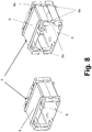
- Fig. 8 and 9 show that the element 5 consists of only two parts 6.
- the element 5 consists of only two identical parts 6.
- the element 5 consists concretely of two parts 6, which are latched together.
- 6 latching tongues 6a are provided on each part, which are latched with complementary to these locking means 6b on the respective other part 6.
- two locking tongues 6a and two locking means 6b are provided on each part 6.
- Fig. 8 and 9 show that the parts 6 form a connecting channel 3 or 4 with a substantially rectangular internal cross-sectional area.
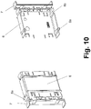
- Fig. 10 shows that the element 5 is connectable or connected to an adapter part 7.
- the adapter part 7 connects the element 5 and the installation housing 1 c with each other when a vertical connection channel 4 is formed.
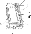
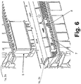
- the adapter part 7 is applied to a strain relief comb 8 of the installation housing 1c. This is in Fig. 1 . Fig. 2 . Fig. 4 . Fig. 5 and Fig. 6 shown.
- Fig. 2 shows a detail view of the vertical connection channel 4 according to Fig. 1 , wherein the adapter part 7 is attached to the strain relief comb 8 of the vertically adjacent installation housing 1c.
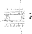
- Fig. 3 shows a detail view of the horizontal connection channel 3 according to Fig. 1 ,
- Fig. 4 shows the arrangement according to Fig. 1 which has three installation housings 1a, 1b, 1c, wherein a first installation housing 1a is connectable by a vertical connection channel 4 and a horizontal connection channel 3 to a below-adjacent or laterally adjacent installation housing 1c, 1b.
- a first installation housing 1a is connectable by a vertical connection channel 4 and a horizontal connection channel 3 to a below-adjacent or laterally adjacent installation housing 1c, 1b.
- the element 5 for forming the horizontal connection channel 3 and in a lower detail view of the element 5 for forming the vertical connection channel 4 is shown.
- Fig. 5 left shows a detail view of the element 5 for forming the vertical connection channel 4 according to Fig. 4 , wherein the adapter part 7 is already attached to the strain relief comb 8 of the vertically adjacent installation housing 1c.
- the element 5 is already arranged on the first installation housing 1a.
- On the right is a detailed view of the element 5 for forming the horizontal connection channel 3 according to Fig. 4 illustrated, wherein the element 5 is already arranged on the first installation housing 1a.
- Fig. 6 shows a detailed view of the element 5 for forming the vertical connection channel 4 according to Fig. 4 wherein the adapter part 7 is already attached to the strain relief comb 8 of the vertically adjacent installation housing 1c and wherein the element 5 is already arranged on the first installation housing 1a.
- Fig. 7 shows a detailed view of the element 5 for forming the horizontal connection channel 3 according to Fig. 4 wherein the element 5 is already arranged on the first installation housing 1a.
Landscapes
- Engineering & Computer Science (AREA)
- Architecture (AREA)
- Civil Engineering (AREA)
- Structural Engineering (AREA)
- Casings For Electric Apparatus (AREA)
- Light Guides In General And Applications Therefor (AREA)
Applications Claiming Priority (1)
| Application Number | Priority Date | Filing Date | Title |
|---|---|---|---|
| DE202017107663.6U DE202017107663U1 (de) | 2017-12-15 | 2017-12-15 | Anordnung, umfassend Installationsgehäuse |
Publications (2)
| Publication Number | Publication Date |
|---|---|
| EP3499663A1 true EP3499663A1 (fr) | 2019-06-19 |
| EP3499663B1 EP3499663B1 (fr) | 2023-05-10 |
Family
ID=61082630
Family Applications (1)
| Application Number | Title | Priority Date | Filing Date |
|---|---|---|---|
| EP18190183.6A Active EP3499663B1 (fr) | 2017-12-15 | 2018-08-22 | Dispositif comportant un boîtier d'installation |
Country Status (4)
| Country | Link |
|---|---|
| EP (1) | EP3499663B1 (fr) |
| DE (1) | DE202017107663U1 (fr) |
| PL (1) | PL3499663T3 (fr) |
| RU (1) | RU2690954C1 (fr) |
Citations (7)
| Publication number | Priority date | Publication date | Assignee | Title |
|---|---|---|---|---|
| FR2738961A1 (fr) * | 1995-09-15 | 1997-03-21 | Alombard Sa | Boite universelle a entraxes multiples et utilisation des boites universelles pour former des blocs modulaires |
| US20030079894A1 (en) * | 2001-11-01 | 2003-05-01 | Weise Gary K. | High volume, high utility junction box |
| EP1835587A1 (fr) * | 2006-03-10 | 2007-09-19 | Schneider Electric Industries Sas | Boîte pour enceinte de tableau |
| DE202008015310U1 (de) * | 2008-11-19 | 2010-04-08 | Weidmüller Interface GmbH & Co. KG | Baugruppe aus zwei oder mehr Anschlussvorrichtungen zur Realisierung von Abzweigungen an durchgehenden Leitern |
| GB2507715A (en) * | 2012-09-04 | 2014-05-14 | Sidi Mohamed Ilias Berhili | Back Box Installation System |
| GB2526766A (en) * | 2014-02-27 | 2015-12-09 | Richard Smith | Easy click box |
| DE102015113900A1 (de) * | 2015-08-21 | 2017-02-23 | Abb Ag | Anordnung aus Installationsgehäusen und Installationsgehäuse |
Family Cites Families (3)
| Publication number | Priority date | Publication date | Assignee | Title |
|---|---|---|---|---|
| RU61955U1 (ru) * | 2006-11-20 | 2007-03-10 | Мария Владимировна Чеклецова | Короб для прокладки кабеля и монтажа электроустановочных изделий |
| DE102010055663A1 (de) * | 2010-12-22 | 2012-06-28 | Schneider Electric Industries Sas | Wandeinsatz |
| DE102013221122A1 (de) * | 2013-10-17 | 2015-04-23 | Hager Electro Gmbh & Co. Kg | Verbindungselement, Kastenteil und Bausatz zur Bildung eines in eine Wandnische einzubauenden Kastens |
-
2017
- 2017-12-15 DE DE202017107663.6U patent/DE202017107663U1/de active Active
-
2018
- 2018-08-22 PL PL18190183.6T patent/PL3499663T3/pl unknown
- 2018-08-22 EP EP18190183.6A patent/EP3499663B1/fr active Active
- 2018-09-21 RU RU2018133480A patent/RU2690954C1/ru active
Patent Citations (7)
| Publication number | Priority date | Publication date | Assignee | Title |
|---|---|---|---|---|
| FR2738961A1 (fr) * | 1995-09-15 | 1997-03-21 | Alombard Sa | Boite universelle a entraxes multiples et utilisation des boites universelles pour former des blocs modulaires |
| US20030079894A1 (en) * | 2001-11-01 | 2003-05-01 | Weise Gary K. | High volume, high utility junction box |
| EP1835587A1 (fr) * | 2006-03-10 | 2007-09-19 | Schneider Electric Industries Sas | Boîte pour enceinte de tableau |
| DE202008015310U1 (de) * | 2008-11-19 | 2010-04-08 | Weidmüller Interface GmbH & Co. KG | Baugruppe aus zwei oder mehr Anschlussvorrichtungen zur Realisierung von Abzweigungen an durchgehenden Leitern |
| GB2507715A (en) * | 2012-09-04 | 2014-05-14 | Sidi Mohamed Ilias Berhili | Back Box Installation System |
| GB2526766A (en) * | 2014-02-27 | 2015-12-09 | Richard Smith | Easy click box |
| DE102015113900A1 (de) * | 2015-08-21 | 2017-02-23 | Abb Ag | Anordnung aus Installationsgehäusen und Installationsgehäuse |
Also Published As
| Publication number | Publication date |
|---|---|
| EP3499663B1 (fr) | 2023-05-10 |
| PL3499663T3 (pl) | 2024-01-03 |
| RU2690954C1 (ru) | 2019-06-07 |
| DE202017107663U1 (de) | 2018-01-15 |
Similar Documents
| Publication | Publication Date | Title |
|---|---|---|
| EP2091105A2 (fr) | Boîtier électronique pouvant être joint | |
| DE112015000589T5 (de) | Erdungsanschlusseinheit | |
| DE69507450T2 (de) | Modulare elektrische Reihenklemmenanordnung | |
| DE112012006722T5 (de) | Verbinderabdeckung und Verbinder-Verbindungsvorrichtung | |
| DE102014115986A1 (de) | Vorrichtung zur Stromversorgung von an einem Regal anzuordnenden Stromverbrauchern | |
| EP3172804B1 (fr) | Cadre de retenue pour modules de connecteurs et/ou connecteurs | |
| EP2248504A1 (fr) | Unité d'alimentation médicale dotée de modules encastrables | |
| DE69009183T2 (de) | Befestigungsmittel. | |
| EP3281253B1 (fr) | Système de rangement en nid d'abeille | |
| EP2681805B1 (fr) | Système de connecteurs enfichables fixés sur des rails de montage | |
| EP3499663B1 (fr) | Dispositif comportant un boîtier d'installation | |
| DE102019107991B4 (de) | Batterieanordnung | |
| EP3312518A1 (fr) | Dispositif de montage du distributeur de fluide | |
| WO2020052920A1 (fr) | Traversée murale pour câbles | |
| DE102005016760B4 (de) | Anordnung elektrischer bzw. elektronischer Geräte | |
| EP3419128A1 (fr) | Multiprise pour une boîte de distribution | |
| DE9315131U1 (de) | Geräteschrank | |
| DE102017115013B3 (de) | Kontaktträgeranordnung und Verfahren zur Montage der Kontaktträgeranordnung | |
| DE102018117125A1 (de) | Zählerfeld mit Modulen | |
| DE102016122969A1 (de) | Anschlussbox für ein system eines luftfahrzeugs | |
| DE7736836U1 (de) | Arbeitstisch mit Kabelkanälen | |
| DE60308458T3 (de) | Installationsdose für elektrische Geräte | |
| DE3727833C2 (fr) | ||
| EP2418746A2 (fr) | Boîtier d'appareillage pour appareils dýinstallation | |
| EP2639910A2 (fr) | Boîtier encastrable pour canaux d'intégration d'appareil et canal d'intégration d'appareils doté de celui-ci |
Legal Events
| Date | Code | Title | Description |
|---|---|---|---|
| PUAI | Public reference made under article 153(3) epc to a published international application that has entered the european phase |
Free format text: ORIGINAL CODE: 0009012 |
|
| STAA | Information on the status of an ep patent application or granted ep patent |
Free format text: STATUS: THE APPLICATION HAS BEEN PUBLISHED |
|
| AK | Designated contracting states |
Kind code of ref document: A1 Designated state(s): AL AT BE BG CH CY CZ DE DK EE ES FI FR GB GR HR HU IE IS IT LI LT LU LV MC MK MT NL NO PL PT RO RS SE SI SK SM TR |
|
| AX | Request for extension of the european patent |
Extension state: BA ME |
|
| STAA | Information on the status of an ep patent application or granted ep patent |
Free format text: STATUS: REQUEST FOR EXAMINATION WAS MADE |
|
| 17P | Request for examination filed |
Effective date: 20191202 |
|
| RBV | Designated contracting states (corrected) |
Designated state(s): AL AT BE BG CH CY CZ DE DK EE ES FI FR GB GR HR HU IE IS IT LI LT LU LV MC MK MT NL NO PL PT RO RS SE SI SK SM TR |
|
| STAA | Information on the status of an ep patent application or granted ep patent |
Free format text: STATUS: EXAMINATION IS IN PROGRESS |
|
| 17Q | First examination report despatched |
Effective date: 20201210 |
|
| GRAP | Despatch of communication of intention to grant a patent |
Free format text: ORIGINAL CODE: EPIDOSNIGR1 |
|
| STAA | Information on the status of an ep patent application or granted ep patent |
Free format text: STATUS: GRANT OF PATENT IS INTENDED |
|
| RIC1 | Information provided on ipc code assigned before grant |
Ipc: H02G 3/08 20060101ALN20230125BHEP Ipc: H05K 5/00 20060101ALN20230125BHEP Ipc: H02B 1/30 20060101ALN20230125BHEP Ipc: H02G 3/12 20060101ALI20230125BHEP Ipc: H02G 3/06 20060101ALI20230125BHEP Ipc: H02G 3/04 20060101AFI20230125BHEP |
|
| INTG | Intention to grant announced |
Effective date: 20230209 |
|
| GRAS | Grant fee paid |
Free format text: ORIGINAL CODE: EPIDOSNIGR3 |
|
| GRAA | (expected) grant |
Free format text: ORIGINAL CODE: 0009210 |
|
| STAA | Information on the status of an ep patent application or granted ep patent |
Free format text: STATUS: THE PATENT HAS BEEN GRANTED |
|
| RAP3 | Party data changed (applicant data changed or rights of an application transferred) |
Owner name: ABB SCHWEIZ AG |
|
| AK | Designated contracting states |
Kind code of ref document: B1 Designated state(s): AL AT BE BG CH CY CZ DE DK EE ES FI FR GB GR HR HU IE IS IT LI LT LU LV MC MK MT NL NO PL PT RO RS SE SI SK SM TR |
|
| REG | Reference to a national code |
Ref country code: GB Ref legal event code: FG4D Free format text: NOT ENGLISH |
|
| RIN1 | Information on inventor provided before grant (corrected) |
Inventor name: ROTH, MICHAEL Inventor name: KILGUS, KAI |
|
| REG | Reference to a national code |
Ref country code: AT Ref legal event code: REF Ref document number: 1567679 Country of ref document: AT Kind code of ref document: T Effective date: 20230515 Ref country code: CH Ref legal event code: EP |
|
| REG | Reference to a national code |
Ref country code: DE Ref legal event code: R096 Ref document number: 502018012106 Country of ref document: DE |
|
| REG | Reference to a national code |
Ref country code: IE Ref legal event code: FG4D Free format text: LANGUAGE OF EP DOCUMENT: GERMAN |
|
| REG | Reference to a national code |
Ref country code: LT Ref legal event code: MG9D |
|
| REG | Reference to a national code |
Ref country code: NL Ref legal event code: MP Effective date: 20230510 |
|
| PG25 | Lapsed in a contracting state [announced via postgrant information from national office to epo] |
Ref country code: SE Free format text: LAPSE BECAUSE OF FAILURE TO SUBMIT A TRANSLATION OF THE DESCRIPTION OR TO PAY THE FEE WITHIN THE PRESCRIBED TIME-LIMIT Effective date: 20230510 Ref country code: PT Free format text: LAPSE BECAUSE OF FAILURE TO SUBMIT A TRANSLATION OF THE DESCRIPTION OR TO PAY THE FEE WITHIN THE PRESCRIBED TIME-LIMIT Effective date: 20230911 Ref country code: NO Free format text: LAPSE BECAUSE OF FAILURE TO SUBMIT A TRANSLATION OF THE DESCRIPTION OR TO PAY THE FEE WITHIN THE PRESCRIBED TIME-LIMIT Effective date: 20230810 Ref country code: NL Free format text: LAPSE BECAUSE OF FAILURE TO SUBMIT A TRANSLATION OF THE DESCRIPTION OR TO PAY THE FEE WITHIN THE PRESCRIBED TIME-LIMIT Effective date: 20230510 Ref country code: ES Free format text: LAPSE BECAUSE OF FAILURE TO SUBMIT A TRANSLATION OF THE DESCRIPTION OR TO PAY THE FEE WITHIN THE PRESCRIBED TIME-LIMIT Effective date: 20230510 |
|
| PG25 | Lapsed in a contracting state [announced via postgrant information from national office to epo] |
Ref country code: RS Free format text: LAPSE BECAUSE OF FAILURE TO SUBMIT A TRANSLATION OF THE DESCRIPTION OR TO PAY THE FEE WITHIN THE PRESCRIBED TIME-LIMIT Effective date: 20230510 Ref country code: LV Free format text: LAPSE BECAUSE OF FAILURE TO SUBMIT A TRANSLATION OF THE DESCRIPTION OR TO PAY THE FEE WITHIN THE PRESCRIBED TIME-LIMIT Effective date: 20230510 Ref country code: LT Free format text: LAPSE BECAUSE OF FAILURE TO SUBMIT A TRANSLATION OF THE DESCRIPTION OR TO PAY THE FEE WITHIN THE PRESCRIBED TIME-LIMIT Effective date: 20230510 Ref country code: IS Free format text: LAPSE BECAUSE OF FAILURE TO SUBMIT A TRANSLATION OF THE DESCRIPTION OR TO PAY THE FEE WITHIN THE PRESCRIBED TIME-LIMIT Effective date: 20230910 Ref country code: HR Free format text: LAPSE BECAUSE OF FAILURE TO SUBMIT A TRANSLATION OF THE DESCRIPTION OR TO PAY THE FEE WITHIN THE PRESCRIBED TIME-LIMIT Effective date: 20230510 Ref country code: GR Free format text: LAPSE BECAUSE OF FAILURE TO SUBMIT A TRANSLATION OF THE DESCRIPTION OR TO PAY THE FEE WITHIN THE PRESCRIBED TIME-LIMIT Effective date: 20230811 |
|
| PG25 | Lapsed in a contracting state [announced via postgrant information from national office to epo] |
Ref country code: FI Free format text: LAPSE BECAUSE OF FAILURE TO SUBMIT A TRANSLATION OF THE DESCRIPTION OR TO PAY THE FEE WITHIN THE PRESCRIBED TIME-LIMIT Effective date: 20230510 |
|
| PG25 | Lapsed in a contracting state [announced via postgrant information from national office to epo] |
Ref country code: SK Free format text: LAPSE BECAUSE OF FAILURE TO SUBMIT A TRANSLATION OF THE DESCRIPTION OR TO PAY THE FEE WITHIN THE PRESCRIBED TIME-LIMIT Effective date: 20230510 |
|
| PG25 | Lapsed in a contracting state [announced via postgrant information from national office to epo] |
Ref country code: SM Free format text: LAPSE BECAUSE OF FAILURE TO SUBMIT A TRANSLATION OF THE DESCRIPTION OR TO PAY THE FEE WITHIN THE PRESCRIBED TIME-LIMIT Effective date: 20230510 Ref country code: SK Free format text: LAPSE BECAUSE OF FAILURE TO SUBMIT A TRANSLATION OF THE DESCRIPTION OR TO PAY THE FEE WITHIN THE PRESCRIBED TIME-LIMIT Effective date: 20230510 Ref country code: RO Free format text: LAPSE BECAUSE OF FAILURE TO SUBMIT A TRANSLATION OF THE DESCRIPTION OR TO PAY THE FEE WITHIN THE PRESCRIBED TIME-LIMIT Effective date: 20230510 Ref country code: EE Free format text: LAPSE BECAUSE OF FAILURE TO SUBMIT A TRANSLATION OF THE DESCRIPTION OR TO PAY THE FEE WITHIN THE PRESCRIBED TIME-LIMIT Effective date: 20230510 Ref country code: DK Free format text: LAPSE BECAUSE OF FAILURE TO SUBMIT A TRANSLATION OF THE DESCRIPTION OR TO PAY THE FEE WITHIN THE PRESCRIBED TIME-LIMIT Effective date: 20230510 Ref country code: CZ Free format text: LAPSE BECAUSE OF FAILURE TO SUBMIT A TRANSLATION OF THE DESCRIPTION OR TO PAY THE FEE WITHIN THE PRESCRIBED TIME-LIMIT Effective date: 20230510 |
|
| REG | Reference to a national code |
Ref country code: DE Ref legal event code: R097 Ref document number: 502018012106 Country of ref document: DE |
|
| PG25 | Lapsed in a contracting state [announced via postgrant information from national office to epo] |
Ref country code: MC Free format text: LAPSE BECAUSE OF FAILURE TO SUBMIT A TRANSLATION OF THE DESCRIPTION OR TO PAY THE FEE WITHIN THE PRESCRIBED TIME-LIMIT Effective date: 20230510 |
|
| PLBE | No opposition filed within time limit |
Free format text: ORIGINAL CODE: 0009261 |
|
| STAA | Information on the status of an ep patent application or granted ep patent |
Free format text: STATUS: NO OPPOSITION FILED WITHIN TIME LIMIT |
|
| REG | Reference to a national code |
Ref country code: CH Ref legal event code: PL |
|
| PG25 | Lapsed in a contracting state [announced via postgrant information from national office to epo] |
Ref country code: MC Free format text: LAPSE BECAUSE OF FAILURE TO SUBMIT A TRANSLATION OF THE DESCRIPTION OR TO PAY THE FEE WITHIN THE PRESCRIBED TIME-LIMIT Effective date: 20230510 |
|
| PG25 | Lapsed in a contracting state [announced via postgrant information from national office to epo] |
Ref country code: LU Free format text: LAPSE BECAUSE OF NON-PAYMENT OF DUE FEES Effective date: 20230822 |
|
| 26N | No opposition filed |
Effective date: 20240213 |
|
| GBPC | Gb: european patent ceased through non-payment of renewal fee |
Effective date: 20230822 |
|
| PG25 | Lapsed in a contracting state [announced via postgrant information from national office to epo] |
Ref country code: LU Free format text: LAPSE BECAUSE OF NON-PAYMENT OF DUE FEES Effective date: 20230822 Ref country code: CH Free format text: LAPSE BECAUSE OF NON-PAYMENT OF DUE FEES Effective date: 20230831 |
|
| PG25 | Lapsed in a contracting state [announced via postgrant information from national office to epo] |
Ref country code: SI Free format text: LAPSE BECAUSE OF FAILURE TO SUBMIT A TRANSLATION OF THE DESCRIPTION OR TO PAY THE FEE WITHIN THE PRESCRIBED TIME-LIMIT Effective date: 20230510 |
|
| REG | Reference to a national code |
Ref country code: BE Ref legal event code: MM Effective date: 20230831 |
|
| REG | Reference to a national code |
Ref country code: IE Ref legal event code: MM4A |
|
| PG25 | Lapsed in a contracting state [announced via postgrant information from national office to epo] |
Ref country code: SI Free format text: LAPSE BECAUSE OF FAILURE TO SUBMIT A TRANSLATION OF THE DESCRIPTION OR TO PAY THE FEE WITHIN THE PRESCRIBED TIME-LIMIT Effective date: 20230510 Ref country code: IT Free format text: LAPSE BECAUSE OF FAILURE TO SUBMIT A TRANSLATION OF THE DESCRIPTION OR TO PAY THE FEE WITHIN THE PRESCRIBED TIME-LIMIT Effective date: 20230510 |
|
| PG25 | Lapsed in a contracting state [announced via postgrant information from national office to epo] |
Ref country code: IE Free format text: LAPSE BECAUSE OF NON-PAYMENT OF DUE FEES Effective date: 20230822 |
|
| PG25 | Lapsed in a contracting state [announced via postgrant information from national office to epo] |
Ref country code: GB Free format text: LAPSE BECAUSE OF NON-PAYMENT OF DUE FEES Effective date: 20230822 |
|
| PG25 | Lapsed in a contracting state [announced via postgrant information from national office to epo] |
Ref country code: IE Free format text: LAPSE BECAUSE OF NON-PAYMENT OF DUE FEES Effective date: 20230822 Ref country code: GB Free format text: LAPSE BECAUSE OF NON-PAYMENT OF DUE FEES Effective date: 20230822 Ref country code: FR Free format text: LAPSE BECAUSE OF NON-PAYMENT OF DUE FEES Effective date: 20230831 |
|
| PG25 | Lapsed in a contracting state [announced via postgrant information from national office to epo] |
Ref country code: BE Free format text: LAPSE BECAUSE OF NON-PAYMENT OF DUE FEES Effective date: 20230831 |
|
| REG | Reference to a national code |
Ref country code: AT Ref legal event code: MM01 Ref document number: 1567679 Country of ref document: AT Kind code of ref document: T Effective date: 20230822 |
|
| PG25 | Lapsed in a contracting state [announced via postgrant information from national office to epo] |
Ref country code: AT Free format text: LAPSE BECAUSE OF NON-PAYMENT OF DUE FEES Effective date: 20230822 |
|
| PG25 | Lapsed in a contracting state [announced via postgrant information from national office to epo] |
Ref country code: AT Free format text: LAPSE BECAUSE OF NON-PAYMENT OF DUE FEES Effective date: 20230822 |
|
| PG25 | Lapsed in a contracting state [announced via postgrant information from national office to epo] |
Ref country code: BG Free format text: LAPSE BECAUSE OF FAILURE TO SUBMIT A TRANSLATION OF THE DESCRIPTION OR TO PAY THE FEE WITHIN THE PRESCRIBED TIME-LIMIT Effective date: 20230510 |
|
| PG25 | Lapsed in a contracting state [announced via postgrant information from national office to epo] |
Ref country code: BG Free format text: LAPSE BECAUSE OF FAILURE TO SUBMIT A TRANSLATION OF THE DESCRIPTION OR TO PAY THE FEE WITHIN THE PRESCRIBED TIME-LIMIT Effective date: 20230510 |
|
| PG25 | Lapsed in a contracting state [announced via postgrant information from national office to epo] |
Ref country code: CY Free format text: LAPSE BECAUSE OF FAILURE TO SUBMIT A TRANSLATION OF THE DESCRIPTION OR TO PAY THE FEE WITHIN THE PRESCRIBED TIME-LIMIT; INVALID AB INITIO Effective date: 20180822 |
|
| PG25 | Lapsed in a contracting state [announced via postgrant information from national office to epo] |
Ref country code: HU Free format text: LAPSE BECAUSE OF FAILURE TO SUBMIT A TRANSLATION OF THE DESCRIPTION OR TO PAY THE FEE WITHIN THE PRESCRIBED TIME-LIMIT; INVALID AB INITIO Effective date: 20180822 |
|
| REG | Reference to a national code |
Ref country code: DE Ref legal event code: R082 Ref document number: 502018012106 Country of ref document: DE Representative=s name: ZIMMERMANN & PARTNER PATENTANWAELTE MBB, DE |
|
| PGFP | Annual fee paid to national office [announced via postgrant information from national office to epo] |
Ref country code: DE Payment date: 20250820 Year of fee payment: 8 |
|
| PGFP | Annual fee paid to national office [announced via postgrant information from national office to epo] |
Ref country code: PL Payment date: 20250816 Year of fee payment: 8 |
|
| PG25 | Lapsed in a contracting state [announced via postgrant information from national office to epo] |
Ref country code: TR Free format text: LAPSE BECAUSE OF FAILURE TO SUBMIT A TRANSLATION OF THE DESCRIPTION OR TO PAY THE FEE WITHIN THE PRESCRIBED TIME-LIMIT Effective date: 20230510 |