EP3500192B1 - Dispositif de traitement d'ablation sélective de tissu - Google Patents
Dispositif de traitement d'ablation sélective de tissu Download PDFInfo
- Publication number
- EP3500192B1 EP3500192B1 EP17816314.3A EP17816314A EP3500192B1 EP 3500192 B1 EP3500192 B1 EP 3500192B1 EP 17816314 A EP17816314 A EP 17816314A EP 3500192 B1 EP3500192 B1 EP 3500192B1
- Authority
- EP
- European Patent Office
- Prior art keywords
- lumen
- surgical instrument
- tissue
- terminal end
- fluid
- Prior art date
- Legal status (The legal status is an assumption and is not a legal conclusion. Google has not performed a legal analysis and makes no representation as to the accuracy of the status listed.)
- Active
Links
Images




Classifications
-
- A—HUMAN NECESSITIES
- A61—MEDICAL OR VETERINARY SCIENCE; HYGIENE
- A61B—DIAGNOSIS; SURGERY; IDENTIFICATION
- A61B17/00—Surgical instruments, devices or methods
- A61B17/32—Surgical cutting instruments
- A61B17/320016—Endoscopic cutting instruments, e.g. arthroscopes, resectoscopes
-
- A—HUMAN NECESSITIES
- A61—MEDICAL OR VETERINARY SCIENCE; HYGIENE
- A61B—DIAGNOSIS; SURGERY; IDENTIFICATION
- A61B17/00—Surgical instruments, devices or methods
- A61B17/32—Surgical cutting instruments
- A61B17/3203—Fluid jet cutting instruments
-
- A—HUMAN NECESSITIES
- A61—MEDICAL OR VETERINARY SCIENCE; HYGIENE
- A61B—DIAGNOSIS; SURGERY; IDENTIFICATION
- A61B17/00—Surgical instruments, devices or methods
- A61B17/00234—Surgical instruments, devices or methods for minimally invasive surgery
-
- A—HUMAN NECESSITIES
- A61—MEDICAL OR VETERINARY SCIENCE; HYGIENE
- A61B—DIAGNOSIS; SURGERY; IDENTIFICATION
- A61B2217/00—General characteristics of surgical instruments
- A61B2217/002—Auxiliary appliance
- A61B2217/005—Auxiliary appliance with suction drainage system
Definitions
- the present disclosure relates to a surgical device for soft tissue treatment, including devices and methods for selectively cutting and removing tissues.
- Tendon injuries are commonly caused by repeated tendon strain, and can range from simple micro tears with inflammation to complete tears and ruptures.
- Healthy tendons include mature, highly-organized, type I collagen fibers, which are capable of withstanding relatively large tensile loads.
- a typical tendon injury, or tendinopathy may be marked by an increased presence of immature, type III collagen, characterized by a loose fibril organization. Increased type III collagen disrupts type I collagen alignment, potentially leading to a loss in strength and increased water retention of the tendon, which in turn, contributes to the cycle of injury and may lead to painful nerve impingement.
- minimally invasive devices and techniques for selectively removing soft tissues or portions of soft tissue, like type III collagen, while leaving healthy tissue undisturbed are desired.
- Conventional minimally invasive techniques may be performed using multiple instruments and entry points into the body. Such techniques may also require various compounds or equipment to enable visualization of a surgical site.
- a device that may reduce the number of entry points or instruments used, safely dislodge and remove pathologic tissue while leaving healthy, native tissues undisturbed, would provide significant advantages to surgeons and patients. Examples of such devices are provided in US5766194A and US2002/0111579A1 .
- US5318518A1 relates to an irrigating catheter which can emit a strong jet to produce a suction effect.
- the present disclosure provides surgical devices and methods for selectively treating soft tissue.
- a surgical instrument in accordance with the claimed invention, includes a handle located at a proximal end of the surgical instrument adapted to be gripped by a user; and an insertion end.
- the insertion end includes a first lumen extending along a longitudinal axis of the surgical instrument.
- the first lumen has a distal end comprising a closed distal terminal end portion and an open proximal end portion attached to the handle.
- An inner bore of the first lumen extends from the open proximal terminal end portion of the first lumen to the closed distal terminal end portion of the first lumen.
- the first lumen also includes only one nozzle formed in a side wall proximate to the closed distal terminal end portion, the nozzle being configured to enable a jet of fluid to exit the nozzle.
- the jet of fluid can selectively cut tissue and can provide a suction force to remove and/or evacuate tissue.
- the insertion end additionally includes a second lumen extending parallel to the first lumen along the longitudinal axis.
- the second lumen has a distal end comprising a closed distal terminal end portion and an open proximal end portion attached to the handle.
- An inner bore of the second lumen extends from the open proximal terminal end portion of the second lumen to the closed distal terminal end portion of the second lumen.
- the inner bore of the second lumen has an inner diameter greater than an inner diameter of the first lumen.
- the first lumen is connected to the second lumen from the proximal end of the insertion end to the closed distal terminal ends of the first lumen and the second lumen.
- the second lumen also includes an aperture formed in a side wall of the second lumen such that the portion of the side wall of the second lumen forming the aperture is disposed abutting and opposite the side wall of the first lumen forming the nozzle to receive therein the jet of fluid exiting the nozzle.
- the first lumen is directly connected to the second lumen from the proximal end of the insertion end to the closed distal terminal end portions of the first lumen and the second lumen, the connection interrupted by the aperture.
- the closed terminal end of the first lumen is located proximal to the closed distal terminal end of the second lumen.
- a method of using a surgical instrument includes selecting a water jet cutting or suction force level on a surgical instrument to provide an adjustable cutting and suction force level; and inserting the surgical instrument into a surgical site.
- the method also includes creating the cutting and suction force with the surgical instrument within the surgical site by operation of the surgical instrument with the selected cutting and suction force level.
- the cutting and suction force is created by pumping a fluid through a nozzle of a first lumen of the surgical instrument into an aperture of a second lumen of the surgical instrument.
- the method further selectively cuts, a first tissue type from multiple (two or more) tissue types within the surgical site and evacuates, by the suction force, the cut first tissue type from the surgical site through the second lumen of the surgical instrument.
- Embodiments of the present surgical instruments and methods allow for selective removal of tissue from a surgical site that limits the number of entry points and/or amount of foreign compound introduced into the body.
- the surgical instrument is configured to create a cutting and suction force between a first lumen and second lumen.
- the cutting and suction force selectively removes a specified tissue type from the surgical site, and the level of force may be adjusted to target a certain soft tissue by setting the fluid pressure travelling through a first lumen.
- the removed tissue is evacuated with a moving fluid through the second lumen. As such the water jet results in a cutting force and suction force, thereby allowing cutting and removal of tissue with one device.
- Fig. 1 is a perspective view of a surgical instrument 100 according to an exemplary embodiment.
- the surgical instrument 100 includes an insertion end 110 attached to a handle 120.
- the insertion end 110 includes a first lumen 113 and a second lumen 116 extending through or otherwise attached to the handle 120.
- the first lumen 113 and the second lumen 116 are depicted and described further in accord with Figs. 2 and 3 , respectively.
- the handle 120 and/or lumens are connected to a pump assembly 130.
- the pump assembly 130 provides a jet of fluid travelling distally along first lumen 113.
- lumen as used herein will be understood to refer to a structure that includes a wall with an open passageway therethrough. Although lumen may otherwise refer to an opening or passage within a tube, it will be understood in the present disclosure to refer to the physical tube or structure itself, and the "first lumen” and “second lumen” will be understood to also include an “inner bore” as discussed below.
- first lumen 113 and second lumen 116 are illustrated as straight tubes or rod-like structures, other shapes may be used.
- the lumens may be curved or angled to allow access to specific anatomic locations.
- other configurations may be included.
- a user may adjust the pressure of the jet of fluid with an adjustor 135.
- the jet of fluid is provided through a supply line 140.
- the jet force is used to cut or resect tissue in a surgical site. Further, the level of force, which can be set by the adjustor 135, can determine the type of tissue cut and removed within the surgical site. The cutting and removal of tissue is discussed with more detail below. Cut tissue is evacuated with a moving fluid at the insertion end 110, through the second lumen 116 and/or handle 120, to the evacuation lumen 150.
- the pump assembly 130 may be any power source connectable to the open proximal terminal end of the first lumen 113 that is suitable to create the suction force at an aperture or opening 118 of the second lumen 116.
- the aperture or opening 118 is depicted and described further in accord with Fig. 3 .
- the pump assembly 130 may be a pump cartridge, peristaltic pump, a configuration with a piston for pumping the jet of fluid through the surgical instrument 100, or any other pump suitable for generation of the jet.
- the piston may be powered by a transmission or any other suitable powering means.
- the pump assembly 130 delivers a pressurized jet of fluid.
- the jet of fluid is water.
- the pump assembly 130 may pump a fluid into the first lumen 113 to form the jet of fluid exiting a nozzle or opening 115.
- the nozzle or opening 115 is depicted and described further in accord with Fig. 2 .
- the supply line 140 may include an inlet line adapted to connect with a fluid source.
- the supply line includes a spike or other connector (e.g., Luer, threaded, or other connector) to attach to a fluid source.
- the fluid source is an IV bag of fluid.
- the supply line 140 may further include a line clamp 141 configured to stop flow of the fluid from the fluid source.
- the supply line 140 may be composed of high pressure tubing.
- the amount of cutting and suction force generated in the surgical instrument 100 may be controllable by a user of the surgical instrument. In one embodiment, the amount of cutting and suction force produced in the surgical instrument 100 may be controlled by the user of the surgical instrument through a console 125.
- the console 125 may be a computing device or a mechanical device.
- a console 125 may include an adjustor 135 operable to control the pressure of the fluid provided to the first lumen 113. The pressure of fluid travelling through the first lumen 113 can affect or determine the amount of force generated between the first lumen 113 and second lumen 116.
- the adjustor 125 may be a keypad in digital or mechanical communication with the pump assembly 130 and able to send commands to the pump assembly 130.
- the console 125 may be a user interface provided by a tablet or other computing device, and the adjustor 135 may be a user interface element displayed thereon that is operable to accept commands for controlling the pump assembly 130.
- the adjustor 135 may be a mechanical device such as a clamp or similar device operable on the fluid line being provided to the surgical instrument 100 without the use of a console 125. The adjustor 135 is discussed further below.
- the surgical instrument 100 may be configured to operate with only a pre-determined amount of water jet force and the force in such a case may not be adjustable by a user of the surgical instrument.
- a controller is placed elsewhere to enable more convenient access to a user.
- the handle 120 is equipped with controllers 121, which allow manual adjustment directly by a user (e.g., by controlling a valve or other mechanism within the device).
- the instrument 100 can include other control mechanisms, e.g., foot pedals, to allow control without interruption of a procedure by the user holding the instrument 100.
- Fig. 2 is a side view with hidden lines visible of a first lumen 113 of the surgical instrument 100 according to an exemplary embodiment.
- the first lumen 113 extends along a longitudinal axis of the surgical instrument 100 from a proximal end 112 of the handle 120 to a distal end 111 of the surgical instrument 100.
- Inner bore 114 of the first lumen 113 extends from an open proximal terminal end of the first lumen 113 to a closed distal terminal end of the first lumen 113.
- the first lumen 113 guides fluid from the pump assembly 130 to the nozzle or opening 115.
- the nozzle or opening 115 is formed in a side wall proximate to the closed distal terminal end of the first lumen 113.
- the inner diameter of the first lumen 113 is 0.33 mm. In some embodiments, the diameter of the nozzle or opening 115 is 0.20 mm. In certain embodiments, the distal end of the nozzle or opening 115 is disposed 0.38 mm from the distal end of the first lumen 113, but variations may be made depending on the specific instrument size.
- the open proximal terminal end of the first lumen 113 may be connectable to an energy source console.
- the energy source console is configurable to drive the surgical instrument 100 with an adjustable energy flow to adjust the cutting and suction force.
- the energy source console includes the pump assembly 130, supply line 140, and the adjustor 135.
- Fig. 3 is a side view with hidden lines visible of a second lumen 116 of the surgical instrument 100 according to an exemplary embodiment.
- the second lumen 116 includes an aperture or opening 118 configured to receive the jet of fluid travelling through nozzle or opening 115 of the first lumen 113.
- the inner diameter of the second lumen 116 is 1.27 mm. In another embodiment, the aperture or opening 118 is 1.65 mm in length. In another embodiment, the distal end of the aperture or opening 118 is disposed 2.06 mm from the distal end of the second lumen 116.
- the open proximal terminal end of the second lumen 116 is connectable to the evacuation lumen 150.
- the second lumen 116 is connected to the evacuation lumen 150 through the handle 120, as depicted in Fig. 1 . Tissue and fluid received by the second lumen 116 is transported to the evacuation lumen 150.
- the evacuation lumen 150 is in communication with a receptacle for storing biological materials such as tissue and fluid.
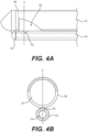
- Fig. 4A is a side view with hidden lines visible of an assembled first lumen 113 and second lumen 116 of the surgical instrument 100 according to the present invention.
- the second lumen 116 is disposed parallel to the first lumen 113 such that the aperture or opening 118 is disposed across from or otherwise aligned with the nozzle or opening 115 and configured to receive the jet of fluid.
- the second lumen 116 extends parallel to the first lumen 113 along the longitudinal axis of the surgical instrument 100, an inner bore 117 of the second lumen 116 extending from an open proximal terminal end of the second lumen 116 to a closed distal terminal end of the second lumen 116.
- the jet of fluid passing through nozzle 115 to aperture 118 enables the generation of a cutting and suction force. Creation of the cutting suction force is described in more detail below.
- Fig. 48 is a cross-section view of an assembled first lumen 113 and second lumen 116 of the surgical instrument 100 according to the present invention.
- the inner bore 117 of the second lumen 116 has an inner diameter greater than an inner diameter of the first lumen 113.
- the width of nozzle or opening 115 is smaller than the width of the aperture or opening 118.
- the first lumen 113 is connected to the second lumen 116 by mechanical fixation, e.g., by welding, clamping, or forming as a unitary structure.
- Fig. 5 is a side view of the distal terminal end 111 of the surgical instrument 100 according to an exemplary embodiment.
- Distal terminal ends 510 and 520 of the first lumen 113 and the second lumen 116, respectively, are closed.
- the closed distal terminal end 510 of the first lumen 113 is shaped to assist moving the insertion end 110 through tissue of a patient.
- the insertion end 110 may be inserted through dermal, fascial, muscular, adipose, or connective tissue (or any other anatomically reasonable tissue) to reach a surgical site.
- the closed distal terminal end 520 of the second lumen 116 extends further than the closed distal terminal end of the first lumen 113.
- the closed distal terminal end 520 of the second lumen 116 is pointed or beveled.
- the insertion end 110 may be guided with the aid of ultrasound or other suitable imaging techniques.
- ultrasound may be used to identify pathologic tissue in a joint or other structure without the aid of fluids.
- Pathologic tissue may be scar tissue, diseased tissue, dead tissue, inflamed tissue, or otherwise undesirable tissue.
- the insertion end 110 may be guided to the pathologic tissue to remove the identified tissue with a suction force.
- the pathologic tissue is type III collagen.
- diseased tissue or tissue otherwise desirable to remove is identified in an elbow joint or other musculo-skeletal structure.
- the angle of the nozzle or opening 115, alignment of insertion end 110 and aperture or opening 118, with relation to second lumen 116 and the surgical site prevents dense tissue from being cut and removed by surgical instrument 100 because, in certain cases, it is too fibrous or is otherwise not as easily cut or removed as other tissue.
- type I collagen has a highly aligned and densely packed structure, capable of withstanding high tensile forces.
- type III collagen is less uniformly aligned and is not capable of withstanding large mechanical forces. As such, type III collagen may be removed at suction levels that may leave nearby type I collagen undisturbed.
- the surgical instrument 100 is suitable for use in different types of living tissue. In certain embodiments, the surgical instrument 100 is suitable for use in human tissue. In some embodiments, the surgical instrument 100 is suitable for use in joints or other musculo-skeletal structures.
- the surgical instrument 100 may be used to remove pathologic tissue from joints.
- the surgical instrument 100 may be used to remove pathologic tissue from tendons in elbow joints.
- the suction force can be adjusted to draw in or remove only selected tissue types, such as type III collagen or other tissue that is potentially pathologic, without disturbing other tissue types in the surgical site, such as type I collagen of healthy tendons.
- different types of tissue withstand different thresholds of cutting and/or suction force, so by controlling the water jet force the types of tissue being removed from the surgical site can be controlled.
- the surgical instrument 100 may be utilized to remove pathologic tissue from different areas of the body, including without limitation, elbow, shoulder, knee, hip, ankle, or wrist joints. In one embodiment, the surgical instrument 100 may be utilized for removal of soft tissue in orthopedic procedures.
- Fig. 6 is a side view with hidden lines visible of a jet of fluid 610 traveling through the surgical instrument 100 according to an exemplary embodiment.
- the water jet force 620 is created when the jet of fluid 610 enters the aperture or opening 118 from the nozzle or opening 115.
- the jet of fluid 610 is a type of fluid capable of being pressurized and dispersed through the nozzle 115.
- the fluid is water.
- the jet of fluid 610 may leave the nozzle or opening 115 at a 55° angle relative to the opposing aperture or opening 118 of the second lumen 116 of the surgical instrument 100.
- the jet of fluid 610 provided through supply line 140 may have a pressure set using the adjustor 135 and console 125 (or other control means) to produce an adequate cutting and/or suction at the distal end 111 to safely resect pathologic tissue.
- the pressure of the jet of fluid 610 can be about, more than about, or less than 0.06, 1.38, 2.76, 4.14, 5.52, 6.90, 13.79, 17.24, 20.68, 24.13, 27.58, 31.03, 34.47,
- the cutting and/ or suction force may be increased by increasing the pressure of the jet of fluid 610.
- the pressure of the jet of fluid 610 may be increased or decreased by a user of the surgical instrument 100 via an adjustor 135.
- the adjustor may be a manual tab for adjusting a power level of the surgical instrument 100, such as a wheel, knob, or lever.
- the adjustor 135 has a fixed number of settings designating predetermined pressures for the jet of fluid 610.
- Table 1 illustrates exemplary pressure levels for water within the jet. Table 1: Exemplary power levels and corresponding average pressures Power Level Average Pressure (MPa) 1 16.51 2 24.64 3 33.65 4 43.05 5 52.83 6 62.59 7 72.38 8 82.87 9 90.20 10 96.97
- the pressure of the jet of fluid 610 pumped through the surgical instrument 100 ranges from 16.51 MPa to 96.97 MPa. In another embodiment, the pressure of the jet of fluid 610 ranges from 16.51 MPa to 82.87 MPa, or from 13.79 to 82.74 MPa. It will be appreciated that other pressure ranges of greater and lesser values are also within the scope of the present disclosure.
- the adjustor 135 may include an adjustment means for adjusting the pressure of the jet of fluid through the pump assembly 130.
- the adjustment means may be at least one knob, button, lever, keypad, or any other suitable means for adjusting the pressure of the jet of fluid 610.
- the adjustment means enables a user of the surgical instrument 100 to select a predetermined power level of pressure. In certain embodiments, the user can select one of ten power levels. In one embodiment, the surgical instrument 100 is configured to provide a predetermined pressure and does not include an adjustor.
- Fig. 7 is a flowchart depicting an exemplary sequence in a method of removing a selected tissue from a surgical site according to an exemplary embodiment not forming part of the claimed invention.
- the method begins after a surgical site is selected at Step 710 when a water force level is selected by a user of the surgical instrument.
- a water force level is selected by a user of the surgical instrument.
- the user may use an adjustor on the surgical instrument 100 to select a pre-determined power level.
- a suitable surgical site may be a joint in a patient.
- the surgical site is an elbow joint.
- the water force level can be selected after at least a first tissue type is identified within the surgical site so that an appropriate suction force level is determined, or based on expected levels for known tissue types.
- the tissue type may be identified through ultrasound or other suitable imaging techniques, or by surgical experience or visual inspection. In some embodiments, multiple tissue types are identified.
- a surgical instrument 100 is inserted into the surgical site.
- an incision or puncture is made in a surgical site to allow insertion of the surgical instrument.
- the surgical instrument 100 may be shaped to move through tissue of a patient.
- a closed distal terminal end 520 of the second lumen 116 of the surgical instrument 100 is shaped to move through tissue of a patient.
- a cutting and suction force is created within the surgical site using the surgical instrument 100 with the selected water force level.
- the water force is created by pumping a fluid through the surgical instrument 100.
- the water force is created by pumping a fluid through a nozzle or opening 115 of a first lumen 113 of the surgical instrument 100 into an aperture or opening 118 of a second lumen 116 of the surgical instrument 100.
- the fluid is a jet of water 610.
- the pressure of the jet of water 610 may be adjusted to control the strength of the cutting or suction force.
- the first tissue type is selectively cut or resected from the surgical site as a result of operation of the surgical instrument 100 with the selected cutting or suction force level.
- type III collagen can be removed from an elbow joint without removing type I collagen tissue by creating a cutting and/or suction force of sufficient strength to resect type III collagen without resecting type I collagen.
- the cut or resected first tissue type is evacuated from the surgical site.
- the cut or resected first tissue type is evacuated from the surgical site with fluid.
- the cut or resected first tissue type and the fluid are evacuated through the second lumen 116 of the surgical instrument 100 to an evacuation lumen 150.
- the tissue type(s) may be defined by a tissue density or other tissue property.
- tissue type if a tendon or other tissue has been damaged or is diseased, the tendon may include more than one type of tissue, as the term "tissue type" should be presently understood.
- the different tissue types may refer to healthy tissue and diseased tissue.
- different tissue types may be identified by variations in tissue density (e.g., due to damage, disease, inflammation, etc). For example, if diseased or damaged tissue is to be removed from within or surrounding a tendon, different tissue types may include tendinous tissue or scar or damaged tissue surrounding or within the tendon, and the tissue types may have variations in density.
- healthy tendon will be understood to have a first density while diseased tissue may have a second density, and as such, different tissues can be identified within a common anatomic structure (e.g., a single tendon), or in a separate structure (e.g., a tendon and surrounding or nearby scar).
- a healthy tissue may have densities, for example, from 1,900 kg/m 3 to approximately 1,700 kg/m 3
- a second tissue type associated with the same tendon, but being damaged or diseased may have a density, for example, from 1,100 kg/m 3 to approximately 1,400 kg/m 3 ; 1,200 kg/m 3 to approximately 1,350 kg/m 3 ; or other ranges therebetween.
- Calcific tendinopathy of the shoulder, elbow, knee or other joints may be treated.
- Calcific tendinopathy can include damaged tendon with areas of weakness, which can also lead to significant morbidity due to pain associated with damaged tissue. Accordingly, removal of tissue affected by such conditions can be beneficial.
- bovine flexor tendons from the ankle joint were harvested and characterized. Ultrasound was used to measure the density of the harvested tendon, which was measured to be approximately 1,900 kg/ms. Tendons were separated into three groups, and subjected to injections of clostridial collagenase type 1 (290 units/mg, SIGMA-ALDRICH CORP.) in a dose escalation study from 1, 10, and 50 mg/ml. No collagenase was administered to a fourth, control group.
- tendon density of the 1 mg/ml group dropped from approximately 1,900 kg/ms to approximately 1,500 kg/ms after 24 hours. 72 hours after collagenase injection, the density further decreased to approximately 1,400 kg/ms.
- the tendon group that was administered 50 mg/ml doses showed a similar pattern, resulting in complete degradation after 3 days.
- the 1, 10, 50 mg/ml, and control groups were treated using the disclosed device and methods at various pressure settings.
- the untreated, control tendon group was resistant to debridement of tissue up to the highest pressure setting. Additionally, neither tissue injury nor removal of any kind occurred.
- the 1 mg/ml group demonstrated similar results when treated with the disclosed device. Minimal tissue removal was observed, until the highest settings were tested. Removal of low density tissue was observed when the 10 and 50 mg/ml collagenase dosage tendon groups were treated with the disclosed device. Particularly, removal of tissue with densities less than around 1,200 to 1,300 kg/m 3 was achieved.
- the disclosed device was able to selectively resect tissues.
- the disclosed device exhibited the capability to safely remove lower-density soft tissue while leaving higher-density soft tissue unperturbed.
Landscapes
- Health & Medical Sciences (AREA)
- Surgery (AREA)
- Life Sciences & Earth Sciences (AREA)
- Engineering & Computer Science (AREA)
- Molecular Biology (AREA)
- Biomedical Technology (AREA)
- Heart & Thoracic Surgery (AREA)
- Medical Informatics (AREA)
- Nuclear Medicine, Radiotherapy & Molecular Imaging (AREA)
- Animal Behavior & Ethology (AREA)
- General Health & Medical Sciences (AREA)
- Public Health (AREA)
- Veterinary Medicine (AREA)
- Orthopedic Medicine & Surgery (AREA)
- Surgical Instruments (AREA)
- Dentistry (AREA)
- Mechanical Engineering (AREA)
Claims (13)
- Un instrument chirurgical (100) comprenant :un manche (120) situé à une extrémité proximale de l'instrument chirurgical adapté pour être saisi par un utilisateur ; une extrémité d'insertion (110) comprenant une première lumière (113) et une seconde lumière (116), la première lumière (113) et la seconde lumière (116) ayant chacune une extrémité distale comprenant une partie d'extrémité terminale distale fermée et une partie d'extrémité proximale ouverte fixée au manche ; la première lumière (113) s'étendant le long d'un axe longitudinal de l'instrument chirurgical (100), un alésage interne de la première lumière (113) s'étendant de la partie d'extrémité terminale proximale ouverte de la première lumière (113) à la partie d'extrémité terminale distale fermée de la première lumière (113), la première lumière (113) comprenant uniquement une buse (115) formée dans une paroi latérale à proximité de la partie d'extrémité terminale distale fermée, la buse (115) étant configurée pour permettre à un jet de fluide de sortir de la buse (115) ; et la seconde lumière (116) s'étendant parallèlement à la première lumière (113) le long de l'axe longitudinal, un alésage intérieur de la seconde lumière (116) s'étendant de la partie d'extrémité terminale proximale ouverte de la seconde lumière (116) à la partie d'extrémité terminale distale fermée de la seconde lumière (116), l'alésage intérieur de la seconde lumière (116) ayant un diamètre intérieur supérieur à un diamètre intérieur de la première lumière (113), la première lumière (113) est reliée à la seconde lumière (116) de l'extrémité proximale de l'extrémité d'insertion (110) aux parties d'extrémité terminale distale fermées de la première lumière (113) et de la seconde lumière (116), la seconde lumière (116) comprenant une ouverture (118) formée dans une paroi latérale de la seconde lumière (116) de telle sorte que la partie de la paroi latérale de la seconde lumière (116) formant l'ouverture (118) soit disposée en butée et à l'opposé de la paroi latérale de la première lumière (113) formant la buse (115) pour recevoir le jet de fluide à l'intérieur, dans laquelle la première lumière (113) est directement reliée à la seconde lumière (116) depuis l'extrémité proximale de l'extrémité d'insertion (110) jusqu'aux parties terminales distales fermées de la première lumière (113) et de la seconde lumière (116), la connexion étant interrompue par l'ouverture (118) ;dans lequel la partie terminale distale fermée de la première lumière (113) est située à proximité de la partie terminale distale fermée de la seconde lumière (116) ; et dans lequel l'instrument chirurgical (100) en fonctionnement fournit une force de coupe et d'aspiration formée au niveau de l'ouverture (118) de la seconde lumière (116), la force d'aspiration tirant sélectivement un premier type de tissu à partir d'une pluralité de types de tissus différents situés dans un site chirurgical dans l'ouverture (118) et la force de coupe coupant le premier type de tissu.
- L'instrument chirurgical (100) selon la revendication 1, comprenant en outre une source d'alimentation pouvant être connectée à la partie d'extrémité terminale proximale ouverte de la première lumière (113) pour créer la force de coupe et d'aspiration au niveau de l'ouverture de la seconde lumière (116).
- L'instrument chirurgical (100) selon la revendication 2, dans lequel la source d'alimentation est un ensemble de pompe (130) qui pompe un fluide dans la première lumière (113) pour former le jet de fluide sortant de la buse (115).
- L'instrument chirurgical (100) selon la revendication 3, dans lequel la diffusion du jet de fluide à travers la buse (115) de la première lumière dans l'ouverture de la seconde lumière (116) crée la force de coupe et d'aspiration.
- L'Instrument chirurgical (100) selon la revendication 4, dans lequel la pression du jet de fluide varie de 16,51 MPa à 96,97 MPa.
- L'instrument chirurgical (100) selon la revendication 5, dans lequel la pression du jet de fluide varie de 16,51 MPa à 82,88 MPa.
- L'instrument chirurgical (100) selon la revendication 1, dans lequel le fluide comprend de l'eau.
- L'instrument chirurgical (100) selon la revendication 1, dans lequel la partie terminale proximale ouverte est reliée à une console de source d'énergie (125).
- L'instrument chirurgical (100) selon la revendication 8, dans lequel la console de source d'énergie (125) est configurable pour entraîner l'instrument chirurgical (100) avec un flux d'énergie réglable pour régler la force de coupe et d'aspiration.
- L'instrument chirurgical (100) selon la revendication 1, dans lequel la partie terminale distale fermée de la seconde lumière (116) est formée de sorte à pouvoir se déplacer à travers le tissu d'un patient.
- L'instrument chirurgical (100) selon la revendication 1, dans lequel la buse (115) a un diamètre de 0,20 mm.
- L'instrument chirurgical (100) selon la revendication 1, dans lequel l'ouverture (118) est de 1,65 mm de longueur.
- L'instrument chirurgical (100) selon la revendication 1, dans lequel l'ouverture (118) s'étend latéralement plus loin que l'étendue latérale de la buse (115).
Applications Claiming Priority (2)
| Application Number | Priority Date | Filing Date | Title |
|---|---|---|---|
| US201662354515P | 2016-06-24 | 2016-06-24 | |
| PCT/US2017/039046 WO2017223479A1 (fr) | 2016-06-24 | 2017-06-23 | Dispositif de traitement d'ablation sélective de tissu |
Publications (4)
| Publication Number | Publication Date |
|---|---|
| EP3500192A1 EP3500192A1 (fr) | 2019-06-26 |
| EP3500192A4 EP3500192A4 (fr) | 2020-05-13 |
| EP3500192C0 EP3500192C0 (fr) | 2025-03-05 |
| EP3500192B1 true EP3500192B1 (fr) | 2025-03-05 |
Family
ID=60675722
Family Applications (1)
| Application Number | Title | Priority Date | Filing Date |
|---|---|---|---|
| EP17816314.3A Active EP3500192B1 (fr) | 2016-06-24 | 2017-06-23 | Dispositif de traitement d'ablation sélective de tissu |
Country Status (3)
| Country | Link |
|---|---|
| US (3) | US10485568B2 (fr) |
| EP (1) | EP3500192B1 (fr) |
| WO (1) | WO2017223479A1 (fr) |
Families Citing this family (4)
| Publication number | Priority date | Publication date | Assignee | Title |
|---|---|---|---|---|
| US10492821B2 (en) | 2016-06-24 | 2019-12-03 | Hydrocision, Inc. | Selective tissue removal treatment device |
| WO2017223479A1 (fr) * | 2016-06-24 | 2017-12-28 | Hydrocision, Inc. | Dispositif de traitement d'ablation sélective de tissu |
| EP3806766B1 (fr) * | 2018-06-14 | 2023-12-13 | Arrinex, Inc. | Systèmes d'administration de médicament pour traiter la cavité nasale |
| EP4613212A1 (fr) | 2024-03-07 | 2025-09-10 | Erbe Elektromedizin GmbH | Appareil et procédé de récupération de cellules en surface |
Citations (1)
| Publication number | Priority date | Publication date | Assignee | Title |
|---|---|---|---|---|
| US5318518A (en) * | 1991-08-14 | 1994-06-07 | Hp Medica Gesellschaft Mbh Fur Medizintechnische Systeme | Irrigating catheter |
Family Cites Families (86)
| Publication number | Priority date | Publication date | Assignee | Title |
|---|---|---|---|---|
| US1889425A (en) | 1931-03-02 | 1932-11-29 | C M Sorensen Co Inc | Medical douche |
| US1902418A (en) | 1931-11-02 | 1933-03-21 | Jensen Salsbery Lab Inc | Surgical instrument |
| US3565062A (en) | 1968-06-13 | 1971-02-23 | Ultrasonic Systems | Ultrasonic method and apparatus for removing cholesterol and other deposits from blood vessels and the like |
| US3590813A (en) | 1969-04-15 | 1971-07-06 | Sunbeam Corp | Oral hygiene appliance |
| US3818913A (en) | 1972-08-30 | 1974-06-25 | M Wallach | Surgical apparatus for removal of tissue |
| US3930505A (en) * | 1974-06-24 | 1976-01-06 | Hydro Pulse Corporation | Surgical apparatus for removal of tissue |
| US4137804A (en) | 1974-07-12 | 1979-02-06 | Gerber Garment Technology, Inc. | Fluid cutting jet receiver |
| US3965901A (en) | 1974-10-03 | 1976-06-29 | American Hospital Supply Corporation | Suction catheter |
| US4024866A (en) | 1974-12-02 | 1977-05-24 | Hydro Pulse Corporation | Surgical apparatus for removal of tissue |
| US4111490A (en) | 1975-09-05 | 1978-09-05 | Liesveld Daniel J | Method and apparatus for channel cutting of hard materials using high velocity fluid jets |
| US4368734A (en) | 1978-01-27 | 1983-01-18 | Surgical Design Corp. | Surgical instrument |
| US4282867A (en) | 1979-12-05 | 1981-08-11 | Christopher Edward | Cleaning fluid injection device |
| US4435902A (en) | 1980-12-16 | 1984-03-13 | Flow Industries, Inc. | Articulated boom water jet cutting apparatus |
| JPS59225049A (ja) | 1983-06-06 | 1984-12-18 | 株式会社 スギノマシン | 手術用ノズル装置 |
| DE8426270U1 (de) | 1984-09-06 | 1985-02-14 | Veltrup, Elmar Michael, Dipl.-Ing., 4150 Krefeld | Vorrichtung zum entfernen von festkoerpern oder ablagerungen aus koerpergefaessen |
| US4715848A (en) | 1985-04-15 | 1987-12-29 | Beroza Gregory A | Gastro-intestinal lavage system and method |
| US5135482A (en) | 1985-12-31 | 1992-08-04 | Arnold Neracher | Hydrodynamic device for the elimination of an organic deposit obstructing a vessel of a human body |
| US4694828A (en) | 1986-04-21 | 1987-09-22 | Eichenbaum Daniel M | Laser system for intraocular tissue removal |
| DE3715418A1 (de) | 1986-05-08 | 1987-11-12 | Olympus Optical Co | Lithotom |
| US4705500A (en) | 1986-07-17 | 1987-11-10 | Mentor O & O, Inc. | Ophthalmic aspirator-irrigator |
| US5057098A (en) | 1987-05-01 | 1991-10-15 | Ophthalmocare, Inc. | Apparatus and method for extracting cataract tissue |
| JPH01198539A (ja) | 1987-10-26 | 1989-08-10 | Marui Ika:Kk | 脳外科用ウオータージェットメス装置 |
| US4935006A (en) | 1987-11-12 | 1990-06-19 | Hasson Harrith M | Suction and irrigation device with right angle and oblique openings |
| SE462414B (sv) | 1988-11-15 | 1990-06-25 | Paal Svedman | Instrument foer avlaegsning av vaevnad |
| US5027792A (en) | 1989-03-17 | 1991-07-02 | Percutaneous Technologies, Inc. | Endoscopic revision hip surgery device |
| US5037431A (en) | 1989-11-03 | 1991-08-06 | The Curators Of The University Of Missouri | Surgical liquid lance apparatus |
| US5135484A (en) | 1990-05-09 | 1992-08-04 | Pioneering Technologies, Inc. | Method of removing plaque from vessels |
| US5195958A (en) | 1990-05-25 | 1993-03-23 | Phillips Edward H | Tool for laparoscopic surgery |
| DE4018736A1 (de) | 1990-06-12 | 1992-01-02 | Wigbert S Prof Dr Med Rau | Hochdruck-aspirationskatheter zur wiedereroeffnung von krankhaft verschlossenen gefaessen |
| CA2048120A1 (fr) | 1990-08-06 | 1992-02-07 | William J. Drasler | Methode et appareil de thrombectomie |
| US5250065A (en) | 1990-09-11 | 1993-10-05 | Mectra Labs, Inc. | Disposable lavage tip assembly |
| US5496267A (en) | 1990-11-08 | 1996-03-05 | Possis Medical, Inc. | Asymmetric water jet atherectomy |
| US5255017A (en) | 1990-12-03 | 1993-10-19 | Hewlett-Packard Company | Three dimensional nozzle orifice plates |
| US5242449A (en) | 1991-04-23 | 1993-09-07 | Allergan, Inc. | Ophthalmic instrument |
| AU656628B2 (en) | 1991-10-18 | 1995-02-09 | United States Surgical Corporation | Endoscopic surgical instrument for aspiration and irrigation |
| US5551448A (en) | 1991-10-18 | 1996-09-03 | United States Surgical Corporation | Endoscopic surgical instrument for aspiration and irrigation |
| DE9200452U1 (de) | 1992-01-16 | 1992-06-04 | Rau, Horst-Günter, Dr.med., 8000 München | Hochfrequenzstromunterstütztes Hochdruckflüssigkeitsstrahlschneidegerät |
| DE4200976C2 (de) | 1992-01-16 | 1995-08-24 | Andreas Pein | Vorrichtung zum Trennen einer biologischen Struktur, insbesondere des menschlichen Gewebes |
| DE4201992A1 (de) | 1992-01-25 | 1993-07-29 | Hp Medica Gmbh Fuer Medizintec | Hochdruck-fluessigkeitsdispensor zur abgabe von steriler fluessigkeit |
| US5217465A (en) | 1992-02-28 | 1993-06-08 | Alcon Surgical, Inc. | Flexible and steerable aspiration tip for microsurgery |
| US5322504A (en) | 1992-05-07 | 1994-06-21 | United States Surgical Corporation | Method and apparatus for tissue excision and removal by fluid jet |
| US5308673A (en) | 1992-05-07 | 1994-05-03 | Minnesota Mining And Manufacturing Company | Stitchbonded absorbent articles and method of making same |
| US5186714A (en) | 1992-05-18 | 1993-02-16 | Yab Revo-Tech Inc. | Multifunctional surgical instrument |
| US5230704A (en) | 1992-06-26 | 1993-07-27 | Biomedical Dynamics Corporation | Suction/irrigation instrument having reusable handle with disposable fluid path |
| US5620414A (en) | 1992-06-30 | 1997-04-15 | Campbell, Jr.; Robert M. | Apparatus and method for effecting surgical incision through use of a fluid jet |
| US5300022A (en) | 1992-11-12 | 1994-04-05 | Martin Klapper | Urinary catheter and bladder irrigation system |
| NL9300626A (nl) | 1993-04-13 | 1994-11-01 | Cordis Europ | Hydrodynamische zuigcatheter. |
| US5358473A (en) * | 1993-04-30 | 1994-10-25 | Mitchell Paul G | Apparatus and method for the removal of adherent viscoelastic material |
| NL9301181A (nl) | 1993-07-05 | 1995-02-01 | Cordis Europ | Werkwijze voor het vervaardigen van een catheter met ten minste één hoge-druklumen en catheter. |
| CA2127637C (fr) | 1993-07-26 | 2006-01-03 | Scott Bair | Instrument chirurgical de coupure a jet de liquide |
| US5476450A (en) | 1993-11-04 | 1995-12-19 | Ruggio; Joseph M. | Apparatus and method for aspirating intravascular, pulmonary and cardiac obstructions |
| US6135977A (en) | 1994-02-16 | 2000-10-24 | Possis Medical, Inc. | Rheolytic catheter |
| NL9401184A (nl) | 1994-07-19 | 1996-03-01 | Cordis Europ | Zuigcatheter. |
| US5527330A (en) | 1994-08-18 | 1996-06-18 | United States Surgical Corporation | Fluid cutting instrument |
| US5556406A (en) | 1994-09-12 | 1996-09-17 | Medjet Inc. | Corneal template and surgical procedure for refractive vision correction |
| US5591184A (en) | 1994-10-13 | 1997-01-07 | Sentinel Medical, Inc. | Fluid jet surgical cutting instrument |
| DE29501973U1 (de) | 1995-02-08 | 1995-04-06 | Pein, Andreas, 19061 Schwerin | Vorrichtung zum Trennen einer biologischen Struktur |
| US5944686A (en) | 1995-06-07 | 1999-08-31 | Hydrocision, Inc. | Instrument for creating a fluid jet |
| US6216573B1 (en) | 1995-06-07 | 2001-04-17 | Hydrocision, Inc. | Fluid jet cutting system |
| US5871462A (en) | 1995-06-07 | 1999-02-16 | Hydrocision, Inc. | Method for using a fluid jet cutting system |
| US5782795A (en) | 1995-06-30 | 1998-07-21 | Xomed Surgical Products, Inc. | Surgical suction cutting instrument with internal irrigation |
| FR2737103B1 (fr) | 1995-07-24 | 1997-10-03 | Saphir Medical Sa | Instrument chirurgical a jet de liquide, tel que bistouri a jet de liquide, a usage unique |
| US5667480A (en) | 1995-10-20 | 1997-09-16 | Ethicon Endo-Surgery, Inc. | Method and devices for endoscopic vessel harvesting |
| DE59705394D1 (de) | 1996-04-25 | 2001-12-20 | Storz Karl Gmbh & Co Kg | Chirurgisches instrumentensystem |
| NL1003056C2 (nl) | 1996-05-07 | 1997-11-10 | Cordis Europ | Zuigkatheter met hemostase-inrichting. |
| US5788667A (en) | 1996-07-19 | 1998-08-04 | Stoller; Glenn | Fluid jet vitrectomy device and method for use |
| US5766194A (en) * | 1996-12-23 | 1998-06-16 | Georgia Skin And Cancer Clinic, Pc | Surgical apparatus for tissue removal |
| AU2022199A (en) | 1997-12-31 | 1999-07-19 | Hydrocision, Inc. | Fluid jet cutting system for cardiac applications |
| FR2780268B1 (fr) | 1998-06-24 | 2000-09-29 | Saphir Medical Sa | Appareil de distribution a deux voies d'un liquide sterile de travail selon des sequences predeterminees pour des applications chirurgicales ou medicales a l'aide d'au moins une piece a main |
| US6280302B1 (en) | 1999-03-24 | 2001-08-28 | Flow International Corporation | Method and apparatus for fluid jet formation |
| US6375635B1 (en) | 1999-05-18 | 2002-04-23 | Hydrocision, Inc. | Fluid jet surgical instruments |
| US6511493B1 (en) | 2000-01-10 | 2003-01-28 | Hydrocision, Inc. | Liquid jet-powered surgical instruments |
| US6451017B1 (en) | 2000-01-10 | 2002-09-17 | Hydrocision, Inc. | Surgical instruments with integrated electrocautery |
| DE60221239T2 (de) | 2001-04-27 | 2008-04-10 | HydroCision, Inc., Billerica | Hochdruckeinwegpumpenkassette zur anwendung auf medizinischem gebiet |
| ATE367122T1 (de) | 2001-11-21 | 2007-08-15 | Hydrocision Inc | Chirurgische flüssigkeitsstrahlinstrumente mit entlang dem strahl ausgerichteten kanalöffnungen |
| US8162966B2 (en) | 2002-10-25 | 2012-04-24 | Hydrocision, Inc. | Surgical devices incorporating liquid jet assisted tissue manipulation and methods for their use |
| US20100331883A1 (en) | 2004-10-15 | 2010-12-30 | Schmitz Gregory P | Access and tissue modification systems and methods |
| DE102004057366B4 (de) | 2004-11-27 | 2009-04-09 | Erbe Elektromedizin Gmbh | Einrichtung für ein Wasserstrahlchirurgiegerät |
| US20060129086A1 (en) | 2004-12-13 | 2006-06-15 | Depuy Mitek, Inc. | Interchangeable tissue macerating and sculpting methods and devices |
| WO2006066160A1 (fr) | 2004-12-14 | 2006-06-22 | Hydrocision, Inc. | Instruments chirurgicaux a jet de liquide |
| KR20080098503A (ko) | 2006-01-24 | 2008-11-10 | 하이드로시젼, 인크 | 선택적으로 제어 가능한 형상을 갖는 말단부를 구비한 액체분사 수술 도구 |
| EP1834601A1 (fr) | 2006-03-16 | 2007-09-19 | Siemens Aktiengesellschaft | Dispositif de traitement d'une onde de choc, comprenant un casier avec couvercle coulissant |
| CN101460101A (zh) | 2006-04-25 | 2009-06-17 | 海德鲁西昂公司 | 电铸成形的液体射流外科器械 |
| US9433427B2 (en) * | 2014-04-08 | 2016-09-06 | Incuvate, Llc | Systems and methods for management of thrombosis |
| US20170312282A1 (en) | 2016-04-28 | 2017-11-02 | The Board Of Trustees Of The Leland Stanford Junior University | Tyrosine kinase inhibitor formulations for the treatment of mast cell-mediated inflammatory diseases and methods of use thereof |
| WO2017223479A1 (fr) * | 2016-06-24 | 2017-12-28 | Hydrocision, Inc. | Dispositif de traitement d'ablation sélective de tissu |
-
2017
- 2017-06-23 WO PCT/US2017/039046 patent/WO2017223479A1/fr not_active Ceased
- 2017-06-23 US US15/631,722 patent/US10485568B2/en active Active
- 2017-06-23 EP EP17816314.3A patent/EP3500192B1/fr active Active
-
2019
- 2019-10-20 US US16/658,107 patent/US11278305B2/en active Active
-
2022
- 2022-03-10 US US17/692,123 patent/US12478400B2/en active Active
Patent Citations (1)
| Publication number | Priority date | Publication date | Assignee | Title |
|---|---|---|---|---|
| US5318518A (en) * | 1991-08-14 | 1994-06-07 | Hp Medica Gesellschaft Mbh Fur Medizintechnische Systeme | Irrigating catheter |
Non-Patent Citations (1)
| Title |
|---|
| SONG XIAO-FEI ET AL: "Waterjet machining of biological tissues in medical surgeries: From soft tissue dissection to bone cutting", JOURNAL OF MANUFACTURING PROCESSES, vol. 107, 1 December 2023 (2023-12-01), US, pages 529 - 548, XP093129524, ISSN: 1526-6125, Retrieved from the Internet <URL:https://www.sciencedirect.com/science/article/pii/S1526612523010253/pdfft?md5=4790b53b64d863c4c89aca4827e45387&pid=1-s2.0-S1526612523010253-main.pdf> [retrieved on 20240209], DOI: 10.1016/j.jmapro.2023.10.067 * |
Also Published As
| Publication number | Publication date |
|---|---|
| US10485568B2 (en) | 2019-11-26 |
| EP3500192C0 (fr) | 2025-03-05 |
| EP3500192A1 (fr) | 2019-06-26 |
| US12478400B2 (en) | 2025-11-25 |
| EP3500192A4 (fr) | 2020-05-13 |
| US20220192694A1 (en) | 2022-06-23 |
| US20200046397A1 (en) | 2020-02-13 |
| US20170367724A1 (en) | 2017-12-28 |
| WO2017223479A1 (fr) | 2017-12-28 |
| US11278305B2 (en) | 2022-03-22 |
Similar Documents
| Publication | Publication Date | Title |
|---|---|---|
| US12478400B2 (en) | Selective tissue removal treatment device | |
| US10492821B2 (en) | Selective tissue removal treatment device | |
| DE60221693T2 (de) | Fettabsaugvorrichtungen und umgebende absaugsysteme | |
| US8366700B2 (en) | Liposuction of visceral fat using tissue liquefaction | |
| JP5489984B2 (ja) | 皮下脂肪を除去するための温水パルス送達式カニューレ型装置 | |
| US20050283216A1 (en) | Apparatus and method for displacing tissue obstructions | |
| DE202011003097U1 (de) | Multi-Ballon-Approximator zur Anastomisierung von Hohllumen | |
| US11904152B2 (en) | Infiltration cannula with dual angle configuration | |
| KR20160079960A (ko) | 내시경 시술용 인젝터 기구 | |
| US20080243102A1 (en) | Apparatus for segmental varicose sclerosis | |
| US20140188039A1 (en) | Liposuction of visceral fat using tissue liquefaction | |
| US20240189506A1 (en) | Infiltration cannula with dual angle configuration | |
| US20240261491A1 (en) | Devices for removal of visceral fat, and related systems and methods | |
| KR20210000199U (ko) | 다중 구조를 갖는 의료용 캐뉼라 | |
| JP5703030B2 (ja) | 組織液化を使用した内臓脂肪の脂肪吸引 | |
| US20140005594A1 (en) | Device and Method for Injecting Pulsed Steam Into a Human or Animal Vessel E.G. a Vein | |
| CA2415129C (fr) | Dispositif chirurgical d'extraction de cellules de tissu d'une structure biologique | |
| US20060106350A1 (en) | Apparatus and methods for treating undesired veins | |
| CN209770488U (zh) | 单管单腔的静脉剥脱器 | |
| CN209770489U (zh) | 静脉剥脱器 | |
| US20240341801A1 (en) | Fasciotomy knife and retractor and method of using same | |
| CN209770486U (zh) | 获取静脉移植物的静脉剥脱器 | |
| CN209770487U (zh) | 防误切割的静脉剥脱器 | |
| CN110141307A (zh) | 静脉剥脱器 | |
| JPH03178669A (ja) | 薬剤噴射注入装置 |
Legal Events
| Date | Code | Title | Description |
|---|---|---|---|
| STAA | Information on the status of an ep patent application or granted ep patent |
Free format text: STATUS: THE INTERNATIONAL PUBLICATION HAS BEEN MADE |
|
| PUAI | Public reference made under article 153(3) epc to a published international application that has entered the european phase |
Free format text: ORIGINAL CODE: 0009012 |
|
| STAA | Information on the status of an ep patent application or granted ep patent |
Free format text: STATUS: REQUEST FOR EXAMINATION WAS MADE |
|
| 17P | Request for examination filed |
Effective date: 20190410 |
|
| AK | Designated contracting states |
Kind code of ref document: A1 Designated state(s): AL AT BE BG CH CY CZ DE DK EE ES FI FR GB GR HR HU IE IS IT LI LT LU LV MC MK MT NL NO PL PT RO RS SE SI SK SM TR |
|
| AX | Request for extension of the european patent |
Extension state: BA ME |
|
| RIN1 | Information on inventor provided before grant (corrected) |
Inventor name: LEWIS, MARK Inventor name: DONNELLY, HOWARD W. Inventor name: MESSINA, LYNNE |
|
| DAV | Request for validation of the european patent (deleted) | ||
| DAX | Request for extension of the european patent (deleted) | ||
| A4 | Supplementary search report drawn up and despatched |
Effective date: 20200417 |
|
| RIC1 | Information provided on ipc code assigned before grant |
Ipc: A61B 17/3203 20060101AFI20200409BHEP |
|
| STAA | Information on the status of an ep patent application or granted ep patent |
Free format text: STATUS: EXAMINATION IS IN PROGRESS |
|
| 17Q | First examination report despatched |
Effective date: 20230613 |
|
| GRAP | Despatch of communication of intention to grant a patent |
Free format text: ORIGINAL CODE: EPIDOSNIGR1 |
|
| STAA | Information on the status of an ep patent application or granted ep patent |
Free format text: STATUS: GRANT OF PATENT IS INTENDED |
|
| INTG | Intention to grant announced |
Effective date: 20240927 |
|
| GRAS | Grant fee paid |
Free format text: ORIGINAL CODE: EPIDOSNIGR3 |
|
| GRAA | (expected) grant |
Free format text: ORIGINAL CODE: 0009210 |
|
| STAA | Information on the status of an ep patent application or granted ep patent |
Free format text: STATUS: THE PATENT HAS BEEN GRANTED |
|
| AK | Designated contracting states |
Kind code of ref document: B1 Designated state(s): AL AT BE BG CH CY CZ DE DK EE ES FI FR GB GR HR HU IE IS IT LI LT LU LV MC MK MT NL NO PL PT RO RS SE SI SK SM TR |
|
| REG | Reference to a national code |
Ref country code: GB Ref legal event code: FG4D |
|
| REG | Reference to a national code |
Ref country code: CH Ref legal event code: EP |
|
| REG | Reference to a national code |
Ref country code: IE Ref legal event code: FG4D |
|
| REG | Reference to a national code |
Ref country code: DE Ref legal event code: R096 Ref document number: 602017088186 Country of ref document: DE |
|
| U01 | Request for unitary effect filed |
Effective date: 20250404 |
|
| U07 | Unitary effect registered |
Designated state(s): AT BE BG DE DK EE FI FR IT LT LU LV MT NL PT RO SE SI Effective date: 20250411 |
|
| U20 | Renewal fee for the european patent with unitary effect paid |
Year of fee payment: 9 Effective date: 20250515 |
|
| PG25 | Lapsed in a contracting state [announced via postgrant information from national office to epo] |
Ref country code: RS Free format text: LAPSE BECAUSE OF FAILURE TO SUBMIT A TRANSLATION OF THE DESCRIPTION OR TO PAY THE FEE WITHIN THE PRESCRIBED TIME-LIMIT Effective date: 20250605 |
|
| PG25 | Lapsed in a contracting state [announced via postgrant information from national office to epo] |
Ref country code: ES Free format text: LAPSE BECAUSE OF FAILURE TO SUBMIT A TRANSLATION OF THE DESCRIPTION OR TO PAY THE FEE WITHIN THE PRESCRIBED TIME-LIMIT Effective date: 20250305 |
|
| PGFP | Annual fee paid to national office [announced via postgrant information from national office to epo] |
Ref country code: GB Payment date: 20250506 Year of fee payment: 9 |
|
| PG25 | Lapsed in a contracting state [announced via postgrant information from national office to epo] |
Ref country code: NO Free format text: LAPSE BECAUSE OF FAILURE TO SUBMIT A TRANSLATION OF THE DESCRIPTION OR TO PAY THE FEE WITHIN THE PRESCRIBED TIME-LIMIT Effective date: 20250605 |
|
| PG25 | Lapsed in a contracting state [announced via postgrant information from national office to epo] |
Ref country code: HR Free format text: LAPSE BECAUSE OF FAILURE TO SUBMIT A TRANSLATION OF THE DESCRIPTION OR TO PAY THE FEE WITHIN THE PRESCRIBED TIME-LIMIT Effective date: 20250305 |
|
| PG25 | Lapsed in a contracting state [announced via postgrant information from national office to epo] |
Ref country code: GR Free format text: LAPSE BECAUSE OF FAILURE TO SUBMIT A TRANSLATION OF THE DESCRIPTION OR TO PAY THE FEE WITHIN THE PRESCRIBED TIME-LIMIT Effective date: 20250606 |
|
| PGFP | Annual fee paid to national office [announced via postgrant information from national office to epo] |
Ref country code: IE Payment date: 20250515 Year of fee payment: 9 |
|
| PG25 | Lapsed in a contracting state [announced via postgrant information from national office to epo] |
Ref country code: SM Free format text: LAPSE BECAUSE OF FAILURE TO SUBMIT A TRANSLATION OF THE DESCRIPTION OR TO PAY THE FEE WITHIN THE PRESCRIBED TIME-LIMIT Effective date: 20250305 |
|
| PG25 | Lapsed in a contracting state [announced via postgrant information from national office to epo] |
Ref country code: PL Free format text: LAPSE BECAUSE OF FAILURE TO SUBMIT A TRANSLATION OF THE DESCRIPTION OR TO PAY THE FEE WITHIN THE PRESCRIBED TIME-LIMIT Effective date: 20250305 |
|
| PGFP | Annual fee paid to national office [announced via postgrant information from national office to epo] |
Ref country code: CH Payment date: 20250701 Year of fee payment: 9 |
|
| PG25 | Lapsed in a contracting state [announced via postgrant information from national office to epo] |
Ref country code: CZ Free format text: LAPSE BECAUSE OF FAILURE TO SUBMIT A TRANSLATION OF THE DESCRIPTION OR TO PAY THE FEE WITHIN THE PRESCRIBED TIME-LIMIT Effective date: 20250305 |
|
| PG25 | Lapsed in a contracting state [announced via postgrant information from national office to epo] |
Ref country code: SK Free format text: LAPSE BECAUSE OF FAILURE TO SUBMIT A TRANSLATION OF THE DESCRIPTION OR TO PAY THE FEE WITHIN THE PRESCRIBED TIME-LIMIT Effective date: 20250305 |
|
| PG25 | Lapsed in a contracting state [announced via postgrant information from national office to epo] |
Ref country code: IS Free format text: LAPSE BECAUSE OF FAILURE TO SUBMIT A TRANSLATION OF THE DESCRIPTION OR TO PAY THE FEE WITHIN THE PRESCRIBED TIME-LIMIT Effective date: 20250705 |
|
| PLBE | No opposition filed within time limit |
Free format text: ORIGINAL CODE: 0009261 |
|
| STAA | Information on the status of an ep patent application or granted ep patent |
Free format text: STATUS: NO OPPOSITION FILED WITHIN TIME LIMIT |
|
| REG | Reference to a national code |
Ref country code: CH Ref legal event code: L10 Free format text: ST27 STATUS EVENT CODE: U-0-0-L10-L00 (AS PROVIDED BY THE NATIONAL OFFICE) Effective date: 20260114 |
|
| PG25 | Lapsed in a contracting state [announced via postgrant information from national office to epo] |
Ref country code: MC Free format text: LAPSE BECAUSE OF FAILURE TO SUBMIT A TRANSLATION OF THE DESCRIPTION OR TO PAY THE FEE WITHIN THE PRESCRIBED TIME-LIMIT Effective date: 20250305 |
|
| 26N | No opposition filed |
Effective date: 20251208 |