EP3500731B1 - Dispositif de coupe et support pour celui-ci - Google Patents
Dispositif de coupe et support pour celui-ci Download PDFInfo
- Publication number
- EP3500731B1 EP3500731B1 EP17842195.4A EP17842195A EP3500731B1 EP 3500731 B1 EP3500731 B1 EP 3500731B1 EP 17842195 A EP17842195 A EP 17842195A EP 3500731 B1 EP3500731 B1 EP 3500731B1
- Authority
- EP
- European Patent Office
- Prior art keywords
- cutting
- axis
- base
- cutting assembly
- movable structure
- Prior art date
- Legal status (The legal status is an assumption and is not a legal conclusion. Google has not performed a legal analysis and makes no representation as to the accuracy of the status listed.)
- Active
Links
Images







Classifications
-
- E—FIXED CONSTRUCTIONS
- E21—EARTH OR ROCK DRILLING; MINING
- E21C—MINING OR QUARRYING
- E21C27/00—Machines which completely free the mineral from the seam
- E21C27/20—Mineral freed by means not involving slitting
- E21C27/22—Mineral freed by means not involving slitting by rotary drills with breaking-down means, e.g. wedge-shaped drills, i.e. the rotary axis of the tool carrier being substantially perpendicular to the working face, e.g. MARIETTA-type
-
- E—FIXED CONSTRUCTIONS
- E21—EARTH OR ROCK DRILLING; MINING
- E21C—MINING OR QUARRYING
- E21C25/00—Cutting machines, i.e. for making slits approximately parallel or perpendicular to the seam
- E21C25/16—Machines slitting solely by one or more rotating saws, cutting discs, or wheels
-
- E—FIXED CONSTRUCTIONS
- E21—EARTH OR ROCK DRILLING; MINING
- E21C—MINING OR QUARRYING
- E21C25/00—Cutting machines, i.e. for making slits approximately parallel or perpendicular to the seam
- E21C25/16—Machines slitting solely by one or more rotating saws, cutting discs, or wheels
- E21C25/18—Saws; Discs; Wheels
-
- E—FIXED CONSTRUCTIONS
- E21—EARTH OR ROCK DRILLING; MINING
- E21C—MINING OR QUARRYING
- E21C27/00—Machines which completely free the mineral from the seam
- E21C27/02—Machines which completely free the mineral from the seam solely by slitting
-
- E—FIXED CONSTRUCTIONS
- E21—EARTH OR ROCK DRILLING; MINING
- E21C—MINING OR QUARRYING
- E21C27/00—Machines which completely free the mineral from the seam
- E21C27/10—Machines which completely free the mineral from the seam by both slitting and breaking-down
- E21C27/12—Machines which completely free the mineral from the seam by both slitting and breaking-down breaking-down effected by acting on the vertical face of the mineral, e.g. by percussive tools
-
- E—FIXED CONSTRUCTIONS
- E21—EARTH OR ROCK DRILLING; MINING
- E21C—MINING OR QUARRYING
- E21C35/00—Details of, or accessories for, machines for slitting or completely freeing the mineral from the seam, not provided for in groups E21C25/00 - E21C33/00, E21C37/00 or E21C39/00
- E21C35/20—General features of equipment for removal of chippings, e.g. for loading on conveyor
-
- E—FIXED CONSTRUCTIONS
- E21—EARTH OR ROCK DRILLING; MINING
- E21D—SHAFTS; TUNNELS; GALLERIES; LARGE UNDERGROUND CHAMBERS
- E21D9/00—Tunnels or galleries, with or without linings; Methods or apparatus for making thereof; Layout of tunnels or galleries
- E21D9/10—Making by using boring or cutting machines
- E21D9/1006—Making by using boring or cutting machines with rotary cutting tools
-
- E—FIXED CONSTRUCTIONS
- E21—EARTH OR ROCK DRILLING; MINING
- E21D—SHAFTS; TUNNELS; GALLERIES; LARGE UNDERGROUND CHAMBERS
- E21D9/00—Tunnels or galleries, with or without linings; Methods or apparatus for making thereof; Layout of tunnels or galleries
- E21D9/10—Making by using boring or cutting machines
- E21D9/1006—Making by using boring or cutting machines with rotary cutting tools
- E21D9/1013—Making by using boring or cutting machines with rotary cutting tools on a tool-carrier supported by a movable boom
- E21D9/102—Making by using boring or cutting machines with rotary cutting tools on a tool-carrier supported by a movable boom by a longitudinally extending boom being pivotable about a vertical and a transverse axis
-
- E—FIXED CONSTRUCTIONS
- E21—EARTH OR ROCK DRILLING; MINING
- E21D—SHAFTS; TUNNELS; GALLERIES; LARGE UNDERGROUND CHAMBERS
- E21D9/00—Tunnels or galleries, with or without linings; Methods or apparatus for making thereof; Layout of tunnels or galleries
- E21D9/10—Making by using boring or cutting machines
- E21D9/1006—Making by using boring or cutting machines with rotary cutting tools
- E21D9/104—Cutting tool fixtures
- E21D9/1046—Vibrating
-
- E—FIXED CONSTRUCTIONS
- E21—EARTH OR ROCK DRILLING; MINING
- E21D—SHAFTS; TUNNELS; GALLERIES; LARGE UNDERGROUND CHAMBERS
- E21D9/00—Tunnels or galleries, with or without linings; Methods or apparatus for making thereof; Layout of tunnels or galleries
- E21D9/10—Making by using boring or cutting machines
- E21D9/1093—Devices for supporting, advancing or orientating the machine or the tool-carrier
Definitions
- the present disclosure relates to mining and excavation machines, and in particular to a cutting device for a mining or excavation machine.
- US 2014/077578 discloses an underground mining machine.
- Hard rock mining and excavation typically requires imparting large energy on a portion of a rock face in order to induce fracturing of the rock.
- One conventional technique includes operating a cutting head having multiple mining picks. Due to the hardness of the rock, the picks must be replaced frequently, resulting in extensive down time of the machine and mining operation.
- Another technique includes drilling multiple holes into a rock face, inserting explosive devices into the holes, and detonating the devices. The explosive forces fracture the rock, and the rock remains are then removed and the rock face is prepared for another drilling operation. This technique is time-consuming and exposes operators to significant risk of injury due to the use of explosives and the weakening of the surrounding rock structure.
- Yet another technique utilizes roller cutting element(s) that rolls or rotates about an axis that is parallel to the rock face, imparting large forces onto the rock to cause fracturing.
- a cutting assembly for a rock excavation machine having a frame is disclosed in claim 1. Further embodiments are disclosed in the dependent claims.
- embodiments of the invention may include hardware, software, and electronic components or modules that, for purposes of discussion, may be illustrated and described as if the majority of the components were implemented solely in hardware.
- aspects of the invention may be implemented in software (for example, stored on non-transitory computer-readable medium) executable by one or more processing units, such as a microprocessor, an application specific integrated circuits ("ASICs"), or another electronic device.
- processing units such as a microprocessor, an application specific integrated circuits ("ASICs"), or another electronic device.
- ASICs application specific integrated circuits
- controllers described in the specification may include one or more electronic processors or processing units, one or more computer-readable medium modules, one or more input/output interfaces, and various connections (for example, a system bus) connecting the components.
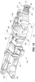
- FIGS. 1 and 2 illustrate an excavation machine or mining machine 10 including a chassis 14, a boom 18, a cutting head or cutting device 22 for engaging a rock face 30 ( FIG. 4 ), and a material gathering head or gathering device 34.
- the chassis 14 is supported on a crawler mechanism 42 for movement relative to a floor (not shown).
- the gathering device 34 includes a deck 50 and rotating arms 54. As the machine 10 advances, the cut material is urged onto the deck 50, and the rotating arms 54 move the cut material onto a conveyor 56 ( FIG. 1 ) for transporting the material to a rear end of the machine 10.
- the arms 54 may slide or wipe across a portion of the deck 50 (rather than rotating) to direct cut material onto the conveyor 56.
- the gathering device 34 may also include a pair of articulated arms 58, each of which supports a bucket 62.
- the articulated arms 58 and buckets 62 may remove material from an area in front of the machine 10 and may direct the material onto the deck 50.
- the boom 18 supports the cutting device 22.
- the boom 18 includes a first portion or base portion 70 and a second portion or wrist portion 74 supporting the cutting device 22.
- the base portion 70 includes a first end 82 coupled to the chassis 14 ( FIG. 2 ) and a second end 86, and the base portion 70 defines a base axis 90 extending between the first end 82 and the second end 86.
- the first end 82 is pivotable relative to the chassis 14 about a transverse axis 94 oriented perpendicular to the base axis 90.
- the transverse axis 94 may be offset from the base axis 90 such that the transverse axis 94 and base axis 90 do not intersect.
- the boom 18 is formed as a first structure 98 proximate the first end 82 and a second structure 100 proximate the second end 86.
- the first structure 98 is pivotable and includes an opening 102 receiving the second structure 100 in an extendable or telescoping manner.
- the first structure 98 is pivotable about the transverse axis 94 and may also be pivoted laterally about a vertical axis or slew axis 104 ( FIG. 1 ) (e.g., by rotation of a turntable coupling).
- the wrist portion 74 is coupled to the movable structure 100 and supported relative to the base portion 70.
- the wrist portion 74 may move or telescope with the second end 86 of the base portion 70, thereby selectively extending and retracting the wrist portion 74 in a direction parallel to the base axis 90.
- the second end 86 is extended and retracted by operation of one or more fluid actuators 164 (e.g., hydraulic cylinders - FIG. 8 ).
- the wrist portion 74 includes a first end 110 and a second end 114 and defines a wrist axis 76. In some embodiments, when the wrist portion 74 is in a rest position, the wrist axis 76 may be oriented substantially parallel to the base axis 90.
- the first end 110 of the wrist portion 74 is supported by the second end 86 of the base portion 70.
- the cutting device 22 is coupled to the second end 114 of the wrist portion 74.
- the cutting device 22 includes a cutting bit or cutting disc 166 having a peripheral edge 170, and a plurality of cutting bits 156 ( FIG. 6 ) positioned along the peripheral edge 170.
- the peripheral edge 170 defines a cutting plane 172, and the cutting disc 166 rotates about a cutter axis 174 ( FIG. 4 ).
- the cutting device 22 further includes a housing 178, an excitation element 150, and a shaft 152 removably coupled (e.g., by fasteners) to the excitation element 150.
- the cutting disc 166 is coupled (e.g., via fasteners) to a carrier 154 that is supported on an end of the shaft 152 for rotation (e.g., by roller bearings) about the cutter axis 174.
- the cutting disc 166 engages the carrier 154 along an inclined surface 182 forming an acute angle relative to the cutting plane 172.
- the cutting disc 166 abuts a surface 182 tapering inwardly toward the cutter axis 174 in a direction oriented away from the housing 178.
- the cutting disc 166 is supported for free rotation relative to the housing 178 (i.e., the cutting disc 166 is neither prevented from rotating nor positively driven to rotate except by induced oscillation).
- the end of the shaft 152 is formed as a stub or cantilevered shaft generally extending parallel to the cutter axis 174.
- the excitation element 150 may include an exciter shaft 158 and an eccentric mass 160 secured to the exciter shaft 158 for rotation with the exciter shaft 158.
- the exciter shaft 158 is driven by a motor 162 and is supported for rotation (e.g., by roller bearings).
- the rotation of the eccentric mass 160 induces an eccentric oscillation in the shaft 152, thereby inducing oscillation of the cutting disc 166.
- the structure of the cutting device 22 and excitation element 150 may be similar to the cutter head and excitation element described in U.S. Patent Application No.
- the cutting device 22 and excitation element 150 may be similar to the exciter member and cutting bit described in U.S. Publication No. 2014/0077578, published March 20, 2014 , the entire contents of which are hereby incorporated by reference.
- the cutter axis 174 is oriented at an angle 186 relative to a tangent of the rock face 30 at a contact point with the cutting disc 166.
- the angle 186 is between approximately 0 degrees and approximately 25 degrees. In some embodiments, the angle 186 is between approximately 1 degree and approximately 10 degrees. In some embodiments, the angle 186 is between approximately 3 degrees and approximately 7 degrees. In some embodiments, the angle 186 is approximately 5 degrees.
- the cutting device 22 engages the rock face 30 by undercutting the rock face 30. That is, a leading edge of the cutting disc 166 engages the rock face 30 such that the cutting disc 166 (e.g., the cutting plane 172) forms a low or small angle relative to the rock face 30 and traverses across a length of the rock face 30 in a cutting direction 190. Orienting the cutting disc 166 at an angle provides clearance between the rock face 30 and a trailing edge of the cutting disc 166 (i.e., a portion of the edge that is positioned behind the leading edge with respect to the cutting direction 190).
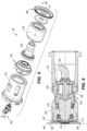
- the wrist portion 74 includes a universal joint or U-joint 128 coupling the first member 122 and the second member 126.
- the first member 122 includes a pair of parallel first lugs 132 and the second member 126 includes a pair of parallel second lugs 136.
- a first shaft 140 is positioned between the first lugs 132 and a second shaft 144 is positioned between the second lugs 136 and is coupled to the first shaft 140.
- the second shaft 144 is rigidly coupled to the first shaft 140.
- the first shaft 140 and second shaft 144 are positioned in a support member 142 and are supported for rotation relative to the lugs 132, 136 by bearings 202, 204, respectively.
- the first shaft 140 defines a first axis 196 that is substantially perpendicular to the wrist axis 76, and the second shaft 144 defines a second axis 198.
- the second axis 198 is substantially perpendicular to the cutter axis 174.
- the first axis 196 and the second axis 198 are oriented perpendicular to each other.
- the universal joint 128 allows the second member 126 to pivot relative to the first member 122 about the first axis 196 and the second axis 198.
- Other aspects of universal joints are understood by a person of ordinary skill in the art and are not discussed in further detail. Among other things, the incorporation of a universal joint permits the cutting device 22 to precess about the axes of the universal joint, and the joint is capable of transferring shear and torque loads.
- the wrist portion 74 further includes a suspension system for controlling movement of the second member 126 relative to the first member 122.
- the suspension system includes multiple fluid cylinders 148 (e.g., hydraulic cylinders).
- the fluid cylinders 148 maintain a desired offset angle between the first member 122 and the second member 126.
- the fluid cylinders 148 act similar to springs and counteract the reaction forces exerted on the cutting device 22 by the rock face 30.
- the suspension system includes four fluid cylinders 148 spaced apart from one another about the wrist axis 76 by an angular interval of approximately ninety degrees.
- the cylinders 148 extend in a direction that is generally parallel to the wrist axis 76, but the cylinders 148 are positioned proximate the end of each of the first shaft 140 and the second shaft 144.
- Each fluid cylinders 148 includes a first end coupled to the first member 122 and a second end coupled to the second member 126.
- the ends of each cylinder 148 may be connected to the first member 122 and the second member 126 by spherical couplings to permit pivoting movement.
- the suspension system transfers the cutting force as a moment across the universal joint 128, and controls the stiffness between the wrist portion 74 and the base portion 70.
- the suspension system may include fewer or more fluid actuators 148.
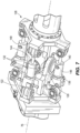
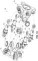
- the fluid actuators 148 may be positioned in a different configuration between the first member 122 and the second member 126 (e.g., see FIG. 11 , in which the hydraulic cylinders 148 are offset from the axes of the shafts 140, 144; stated another way, each cylinder 148 may extend between a corner of the first member 122 and a corresponding corner of the second member 126).
- the suspension system may incorporate one or more mechanical spring element(s), either instead of or in addition to the fluid cylinders 148.
- FIG. 12 shows another embodiment of the boom 418 including a wrist portion 474 which does not however fall under the scope of the claims.
- the wrist portion 474 may include a first member 522 that pivots about a first pivot pin 538 and a second member 526 that pivots about a second pivot pin 542 that is offset from the first pivot pin 538.
- the first member 522 and the second member 526 may pivot about perpendicular, offset axes.
- the first member 522 forms a first end of the wrist portion 474.
- the second member 526 forms the second end 514 of the wrist portion 474 and supports the cutting device 22.
- the first member 522 is coupled to the base portion 470 by the first pivot pin 538, and the second member 526 is coupled to the first member 522 by the second pivot pin 542.
- the first pivot pin 538 provides a first pivot axis 550 oriented perpendicular to the base axis 490 and permits the first member 522 to pivot relative to the base portion 470 in a plane containing axis 490.
- the second pivot pin 542 provides a second pivot axis 554 oriented transverse to the base axis 490 and perpendicular to the first pivot axis 550, permitting the second member 526 to pivot relative to the first member 522 in a vertical plane.
- the first member 522 is pivoted about the first pivot axis 550 by actuation of a first actuator 558
- the second member 526 is pivoted about the second pivot axis 554 by actuation of a second actuator 562.
- FIGS. 13 and 14 shows another embodiment of the boom 818 including a wrist portion 874 supported by multiple articulating boom portions, which does not however fall under the scope of the claims.
- a base portion 870 of the boom 818 includes a first member or first structure 898 and a second member or second structure 900 pivotably coupled to the first structure 898.
- the first structure 898 is supported on a slew coupling 906 for pivoting the boom 818 in a lateral plane about a slew axis 904.
- the first structure 898 is pivotable relative to the slew coupling 906 about a first axis 894 oriented transverse to the slew axis 904, and the second structure 900 is pivotable relative to the first structure 898 about a second axis 896 oriented parallel to the first axis 894.
- the slew coupling 906 may be driven to pivot by actuators (e.g., hydraulic cylinders - not shown).
- the first structure 898 is driven to pivot about the first axis 894 by first actuators 908, and the second structure 900 is driven to pivot about the second axis 896 by second actuators 912.
- the first axis 894 and second axis 896 both extend in a transverse orientation, thereby providing two independently articulating luff portions to provide significant versatility for pivoting the cutting device in a vertical plane.
- the first structure and second structure may pivot in a different manner.
- the wrist portion 874 is secured to an end of the second structure 900 distal from the first structure 898, and the cutting device 22 is supported by the wrist portion 874.
- the first member 122 of the wrist portion 74 is coupled to the movable structure 100 of the base portion 70.
- a fluid manifold 194 e.g., a sandwich manifold
- a linear actuator 164 e.g., a hydraulic piston-cylinder device
- One end (e.g., a rod end) of the linear actuator 164 may be connected to the first structure 98, and another end (e.g., a cylinder end) of the actuator 164 may be connected to the manifold 194.
- the linear actuator 164 may have cylinder chambers in fluid communication with the manifold 194.
- Extension of the linear actuator 164 causes extension of the movable structure 100 in a direction parallel to the boom axis 90, and retraction of the linear actuator 164 causes retraction of the movable structure 100 in a direction parallel to the boom axis 90.
- a sensor 168 is coupled between an outer surface of the first structure 98 and the manifold 194.
- the sensor 168 may include a transducer for measuring the stroke or position of the linear actuator 164 and the movable structure 100.
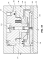
- the movable structure 100 is supported relative to the first structure 98 by bearing assemblies 172.
- eight bearing assemblies 172 are located in a common plane normal to the base axis 90, with two bearing assemblies 172 abutting each of the four sides of the movable structure 100.
- An additional set of eight bearing assemblies may be positioned in a similar manner in a second plane normal to the base axis 90 and offset from the plane illustrated in FIG. 9 .
- the base portion 70 may include fewer or more bearing assemblies 172, and the bearing assemblies 172 may be positioned in multiple planes along the length of the base axis 90.
- the bearing assemblies 172 may be positioned in a different manner.
- each bearing assembly 172 includes a main support 176 secured to the base portion 70 and a pad 180 abutting a surface of the movable structure 100.
- a spherical bearing member 184 is coupled to the main support 176 to permit pivoting movement of the pad 180 relative to the main support 176.
- the pad 180 includes one or more pockets or chambers or galleries 206 formed in a surface of the pad 180 adjacent the movable structure 100.
- the main support 176 includes a port 210 and a passage 214 providing communication between the port 210 and galleries 206.
- the port 210 may receive a lubricant (e.g.
- a hard, low-friction bearing surface 218 is secured to an outer surface of the movable structure 100.
- the bearing surface 218 may be removably secured to the movable structure 100 (e.g., by fasteners) or attached by fusion (e.g., welding).
- the bearing assemblies 172 provide a low-friction interface and are capable of transmitting large forces caused by the cutting operation.
- a shim pack 222 may be positioned between the main support 176 and the first structure 98 to adjust the position of the main support 176.
- a spring pack 226 may be positioned between the main support 176 and the spherical bearing member 184 to provide an initial load or preload to ensure that the pad 180 maintains positive contact with the movable structure 100 during operation. In other embodiments, other types of bearing assemblies may be used.
Landscapes
- Engineering & Computer Science (AREA)
- Mining & Mineral Resources (AREA)
- Geology (AREA)
- Life Sciences & Earth Sciences (AREA)
- General Life Sciences & Earth Sciences (AREA)
- Geochemistry & Mineralogy (AREA)
- Mechanical Engineering (AREA)
- Environmental & Geological Engineering (AREA)
- Earth Drilling (AREA)
- Working Measures On Existing Buildindgs (AREA)
- Processing Of Stones Or Stones Resemblance Materials (AREA)
- Crushing And Grinding (AREA)
- Shearing Machines (AREA)
Claims (13)
- Ensemble de coupe (10) pour une machine d'excavation de roche comprenant un châssis, l'ensemble de coupe comprenant :une flèche (18) comprenant une première partie (70) et une seconde partie (74), la première partie (70) étant conçue pour être supportée par le châssis, la seconde partie (74) étant accouplée de manière pivotante à la première partie (70) par un joint universel, la première partie (70) comprenant une base (98) et une structure mobile (100), la base (98) s'étendant le long d'un axe de base longitudinal (90), la structure mobile (100) étant accouplée à la seconde partie (74) par le joint universel (128), la structure mobile (100) étant supportée pour un mouvement par rapport à la base (98) dans une direction parallèle à l'axe de base longitudinal (90) ; etun dispositif (22) de coupe supporté par la seconde partie de la flèche (18).
- Ensemble de coupe selon la revendication 1, dans lequel le joint universel (128) comprend un premier arbre (140) accouplé à la première partie (70) et s'étendant le long d'un premier axe (196), le joint universel (128) comprenant en outre un second arbre (144) accouplé à la seconde partie (74) et s'étendant le long d'un second axe (198), le second arbre (144) étant accouplé de manière pivotante au premier arbre (140) pour permettre un mouvement de pivotement de la seconde partie (74) par rapport à la première partie (70) autour du premier axe (196) et autour du second axe (198).
- Ensemble de coupe selon la revendication 1, comprenant en outre au moins un élément de sollicitation (148) accouplé entre la première partie (70) et la seconde partie (74), ledit au moins un élément de sollicitation (148) sollicitant la seconde partie (74) vers une orientation prédéterminée par rapport à la première partie (70).
- Ensemble de coupe selon la revendication 3, dans lequel ledit au moins un élément de sollicitation (148) comprend une pluralité d'éléments de sollicitation (148) espacés les uns des autres autour de l'axe de base longitudinal (90).
- Ensemble de coupe selon la revendication 1, dans lequel le dispositif (22) de coupe comprend un disque de coupe (166) ayant un bord de coupe positionné dans un plan de coupe (172), le plan de coupe (172) étant orienté dans une direction sensiblement perpendiculaire à un axe longitudinal (76) de la seconde partie (74) de la flèche (18), une surface de base du disque de coupe (166) venant en butée contre une surface (182) d'un support (154) le long d'un plan formant un angle aigu par rapport au plan de coupe (172).
- Ensemble de coupe selon la revendication 1, dans lequel le dispositif (22) de coupe comprend un disque de coupe (166) et un dispositif (150) d'excitation ; le dispositif (150) d'excitation comprenant une masse excentrique (160) supportée pour une rotation de manière excentrique et positionnée à proximité du disque de coupe (166), dans laquelle la rotation de la masse excentrique (160) induit une oscillation du dispositif (22) de coupe.
- Ensemble de coupe selon la revendication 1, dans lequel
au moins un palier (172) supportant la structure mobile (100) pour un mouvement par rapport à la base (98), ledit au moins un palier (172) comprenant un support principal (172) et un patin (180), le support principal (176) étant fixé à la base (98), le patin (180) venant en butée contre une surface de la structure mobile (100). - Ensemble de coupe selon la revendication 7, dans lequel ledit au moins un palier (172) comprend un élément (184) ayant une surface sphérique pour permettre un mouvement de pivotement du patin (180) par rapport au support principal (176).
- Ensemble de coupe selon la revendication 7, dans lequel le tampon (180) comprend une poche positionnée adjacente à la surface de la structure mobile (100), la poche recevant un milieu lubrifiant pour faciliter le mouvement de la structure mobile (100) par rapport au tampon (180).
- Ensemble de coupe selon la revendication 9, dans lequel ledit au moins un palier (172) comprend un passage en communication fluidique avec la poche, le passage étant en communication fluidique avec un orifice d'entrée (210) positionné à proximité d'une surface extérieure de la base (98).
- Ensemble de coupe selon la revendication 7, dans lequel ledit au moins un palier (172) comprend en outre un élément de sollicitation (226) pour solliciter le tampon (180) contre la surface de la structure mobile (100).
- Ensemble de coupe selon la revendication 7, comprenant en outre un actionneur à fluide (164) s'étendant au moins partiellement à travers une chambre intérieure de la base (98) et la structure mobile (100), l'actionneur à fluide (164) comprenant une première extrémité accouplée à la base (98) et une seconde extrémité accouplée à la structure mobile (100), l'actionneur à fluide (164) pouvant être actionné pour déplacer la structure mobile (100) par rapport à la base (98).
- Ensemble de coupe selon la revendication 7, dans lequel ledit au moins un palier (172) comprend au moins un palier (172) supportant chaque côté de la structure mobile (100).
Priority Applications (1)
| Application Number | Priority Date | Filing Date | Title |
|---|---|---|---|
| EP25166756.4A EP4553272A3 (fr) | 2016-08-19 | 2017-08-18 | Dispositif de coupe et support pour celui-ci |
Applications Claiming Priority (4)
| Application Number | Priority Date | Filing Date | Title |
|---|---|---|---|
| US201662377150P | 2016-08-19 | 2016-08-19 | |
| US201662398834P | 2016-09-23 | 2016-09-23 | |
| US201662398717P | 2016-09-23 | 2016-09-23 | |
| PCT/US2017/047566 WO2018035436A1 (fr) | 2016-08-19 | 2017-08-18 | Dispositif de coupe et support pour celui-ci |
Related Child Applications (1)
| Application Number | Title | Priority Date | Filing Date |
|---|---|---|---|
| EP25166756.4A Division EP4553272A3 (fr) | 2016-08-19 | 2017-08-18 | Dispositif de coupe et support pour celui-ci |
Publications (3)
| Publication Number | Publication Date |
|---|---|
| EP3500731A1 EP3500731A1 (fr) | 2019-06-26 |
| EP3500731A4 EP3500731A4 (fr) | 2020-09-16 |
| EP3500731B1 true EP3500731B1 (fr) | 2025-04-02 |
Family
ID=61191397
Family Applications (2)
| Application Number | Title | Priority Date | Filing Date |
|---|---|---|---|
| EP17842195.4A Active EP3500731B1 (fr) | 2016-08-19 | 2017-08-18 | Dispositif de coupe et support pour celui-ci |
| EP25166756.4A Pending EP4553272A3 (fr) | 2016-08-19 | 2017-08-18 | Dispositif de coupe et support pour celui-ci |
Family Applications After (1)
| Application Number | Title | Priority Date | Filing Date |
|---|---|---|---|
| EP25166756.4A Pending EP4553272A3 (fr) | 2016-08-19 | 2017-08-18 | Dispositif de coupe et support pour celui-ci |
Country Status (11)
| Country | Link |
|---|---|
| US (3) | US10738608B2 (fr) |
| EP (2) | EP3500731B1 (fr) |
| CN (1) | CN109844262B (fr) |
| AU (3) | AU2017312142B2 (fr) |
| CA (1) | CA3033866A1 (fr) |
| CL (2) | CL2019000450A1 (fr) |
| FI (1) | FI3500731T3 (fr) |
| PE (1) | PE20190494A1 (fr) |
| PL (1) | PL3500731T3 (fr) |
| RU (1) | RU2752854C2 (fr) |
| WO (1) | WO2018035436A1 (fr) |
Families Citing this family (8)
| Publication number | Priority date | Publication date | Assignee | Title |
|---|---|---|---|---|
| PL3656977T3 (pl) | 2012-09-14 | 2024-03-04 | Joy Global Underground Mining Llc | Głowica wrębiarki do maszyny górniczej |
| FI3408499T3 (fi) | 2016-01-27 | 2023-06-05 | Joy Global Underground Mining Llc | Useilla leikkuripäillä varustettu kaivoskone |
| US10738608B2 (en) | 2016-08-19 | 2020-08-11 | Joy Global Underground Mining Llc | Cutting device and support for same |
| AU2017330401B2 (en) | 2016-09-23 | 2023-02-09 | Joy Global Underground Mining Llc | Machine supporting rock cutting device |
| FI3814608T3 (fi) * | 2018-07-25 | 2025-01-22 | Joy Global Underground Mining Llc | Kokoonpano kallioleikkausta varten |
| CN110857628B (zh) * | 2018-08-23 | 2025-11-25 | 上海创力集团股份有限公司 | 一种掘进机硬岩截割装置 |
| EP3656975B1 (fr) * | 2018-11-23 | 2023-04-26 | Sandvik Mining and Construction Tools AB | Coupe-disque pour machines d'alésage de tunnels et son procédé de fabrication |
| CN120858218A (zh) | 2023-01-20 | 2025-10-28 | 久益环球地下采矿有限责任公司 | 切割装置和用于切割装置的支撑件 |
Family Cites Families (161)
| Publication number | Priority date | Publication date | Assignee | Title |
|---|---|---|---|---|
| US1510628A (en) | 1924-10-07 | morgan | ||
| US1304352A (en) | 1919-05-20 | Appabatus foe mining | ||
| US1093787A (en) | 1909-10-30 | 1914-04-21 | Harry A Kuhn | Method of tunneling. |
| US1953326A (en) | 1913-06-23 | 1934-04-03 | Olive Eugenie Morgan | Method of mining coal |
| US1735583A (en) | 1913-07-05 | 1929-11-12 | Morgan Olive Eugene | Apparatus for mining coal |
| US1340731A (en) | 1913-08-04 | 1920-05-18 | Edmund C Morgan | Mining and loading machine |
| US2336335A (en) | 1942-08-13 | 1943-12-07 | John A Zublin | Rotary hammering bit |
| US2336337A (en) | 1942-08-13 | 1943-12-07 | John A Zublin | Heavy duty gyrating bit |
| US2466709A (en) | 1944-10-02 | 1949-04-12 | Richard D Karr | Tunneling machine |
| US2745651A (en) | 1947-07-08 | 1956-05-15 | Gewerk Eisenhuette Westfalia | Mining planer |
| US2517267A (en) | 1949-03-07 | 1950-08-01 | George C Watson | Attachment for the cutter bars of mining machines |
| US2756039A (en) | 1949-04-08 | 1956-07-24 | Joy Mfg Co | Guides for flexible elements of coal mining apparatus |
| US2654586A (en) * | 1950-02-04 | 1953-10-06 | Goodman Mfg Co | Digging machine for mining coal |
| US2619338A (en) | 1950-11-03 | 1952-11-25 | Goodman Mfg Co | Coal mining machine |
| US2619339A (en) | 1950-12-11 | 1952-11-25 | Goodman Mfg Co | Mining machine |
| US2659585A (en) | 1951-06-29 | 1953-11-17 | Goodman Mfg Co | Power drive connection for combined rotatable and oscillatable mining tools |
| US2776823A (en) | 1954-05-17 | 1957-01-08 | Joy Mfg Co | Rotating cutter and core breaker for continuous miner |
| US3197256A (en) | 1961-01-23 | 1965-07-27 | Goodman Mfg Co | Continuous mining machine with loading means |
| SU150061A1 (ru) | 1961-08-14 | 1961-11-30 | А.М. Чичота | Устройство дл проверки часовых механизмов и секундомеров |
| US3157437A (en) | 1962-09-19 | 1964-11-17 | Goodman Mfg Co | Continuous mining machine of the oscillating head type |
| GB1039981A (en) | 1963-10-02 | 1966-08-24 | Greenside Machine Co Ltd | Improvements in or relating to heading and ripping machines for mining |
| US3353871A (en) | 1964-08-05 | 1967-11-21 | Lee Norse Co | Continuous mining machine with oscillating rotary cutter heads |
| US3408109A (en) | 1965-07-09 | 1968-10-29 | Mining Progress Inc | Mining machine with rocker arm controlled front pusher plate |
| DE1257713B (de) | 1965-07-26 | 1968-01-04 | Bergwerksverband Gmbh | Antrieb fuer drehend arbeitende Bohrmaschinen zum Vortrieb von soehligen bis seigeren Grubenbauen |
| US3302974A (en) | 1966-02-18 | 1967-02-07 | Westinghouse Air Brake Co | Ripper type mining machine having oppositely moving oscillating ripper heads |
| DE1534648C3 (de) | 1966-03-19 | 1975-08-21 | Atlas Copco Mct Ab, Nacka (Schweden) | Vortriebsmaschine für Tunnels, Stollen, Kanäle od.dgl |
| US3355215A (en) | 1966-11-07 | 1967-11-28 | Smith Ind International Inc | Oscillating tunneling machine |
| GB1311094A (en) | 1969-03-25 | 1973-03-21 | Dubois M | Machine and process for digging undergrojnd galleries |
| SU619117A3 (ru) | 1969-08-06 | 1978-08-05 | Коул Индастри (Патентс) Лимитед (Фирма) | Исполнительный орган барабанного типа дл горной машины |
| US3647263A (en) | 1970-03-19 | 1972-03-07 | Atlas Copco Ab | Tunnelling machines and the like |
| DE2018778A1 (fr) | 1970-04-18 | 1971-12-30 | ||
| AU466244B2 (en) | 1970-08-18 | 1975-10-07 | James S. Robbins And Associates, Inc | Vibrator systems and rock cutter type utilization mechanisms |
| US3719404A (en) * | 1970-11-17 | 1973-03-06 | Kidde & Co Walter | Crane boom having universally swiveled wear pads |
| SU750061A1 (ru) | 1971-12-21 | 1980-07-23 | За витель А. Н. Супрунов | Исполнительный орган горного комбайна |
| SU514097A1 (ru) | 1973-04-10 | 1976-05-15 | Шахта "Нагорная" Комбината "Южкузбассуголь" | Проходческий комбайн |
| FR2229855B1 (fr) * | 1973-05-16 | 1977-10-07 | Eickhoff Geb | |
| US3840271A (en) | 1973-06-27 | 1974-10-08 | Robbins Co | Tunneling machine having swinging arms carrying cutter discs |
| LU68289A1 (fr) | 1973-08-22 | 1975-05-21 | ||
| LU68283A1 (fr) | 1973-08-22 | 1975-05-21 | ||
| US3922017A (en) | 1973-08-23 | 1975-11-25 | Caterpillar Tractor Co | Impact material fracturing device for excavators and the like |
| US3972571A (en) * | 1973-09-14 | 1976-08-03 | The Warner & Swasey Company | Boom slider assembly |
| US3966258A (en) | 1974-12-16 | 1976-06-29 | Joy Manufacturing Company | Mining boom linkage for separate sump and swing cutting |
| US4096917A (en) | 1975-09-29 | 1978-06-27 | Harris Jesse W | Earth drilling knobby bit |
| AT342537B (de) | 1976-05-13 | 1978-04-10 | Voest Ag | Schrammaschine |
| SU581263A1 (ru) | 1976-07-08 | 1977-11-25 | Научно-Исследовательский Горнорудный Институт | Исполнительный орган проходческого комбайна |
| US4087131A (en) | 1976-11-01 | 1978-05-02 | Rapidex, Inc. | Drag bit excavation |
| DE2809132A1 (de) | 1978-03-03 | 1979-09-06 | Gewerk Eisenhuette Westfalia | Bergbau-gewinnungsmaschine |
| DE2836131C2 (de) | 1978-08-18 | 1986-11-27 | Gewerkschaft Eisenhütte Westfalia GmbH, 4670 Lünen | Schildvortriebseinrichtung |
| JPS5540058U (fr) | 1978-09-07 | 1980-03-14 | ||
| US4230372A (en) * | 1978-12-04 | 1980-10-28 | H. B. Zachry Company | Dual rock cutter wheel trencher |
| SU804832A1 (ru) | 1978-12-06 | 1981-02-15 | Криворожский Ордена Трудового Красногознамени Горнорудный Институт | Исполнительный орган проходческогоКОМбАйНА |
| GB2037844B (en) | 1978-12-15 | 1982-10-13 | Coal Industry Patents Ltd | Cutter unit assemblies for excavating machines and to excavating machines including cutter unit assemblies |
| US4662684A (en) * | 1979-12-13 | 1987-05-05 | H. B. Zachery Corporation | Rotary rock and trench cutting saw |
| US4363519A (en) | 1980-10-14 | 1982-12-14 | Joy Manufacturing Company | Continuous mining machine |
| US4377311A (en) | 1981-02-04 | 1983-03-22 | Fox Manufacturing Company Pty. Limited | Multi-purpose mining machine |
| SU962626A1 (ru) | 1981-03-27 | 1982-09-30 | Тульский Ордена Трудового Красного Знамени Политехнический Институт | Исполнительный орган проходческого комбайна |
| US4372403A (en) | 1981-09-14 | 1983-02-08 | Beeman Archie W | Eccentric rotary bit |
| US4516807A (en) | 1981-10-13 | 1985-05-14 | Coal Industry (Patents) Limited | Fluid supply systems for rotary cutter heads for mining machines and rotary cutter heads comprising fluid supply systems |
| DE3235009A1 (de) * | 1982-01-29 | 1983-08-25 | Friedrich Wilhelm Paurat | Verfahren zum betrieb einer teilschnittmaschine und fuer das verfahren eingerichtete teilschnittmaschine |
| DE3327941A1 (de) | 1983-08-03 | 1985-02-21 | Gewerkschaft Eisenhütte Westfalia, 4670 Lünen | Abbau- und vortriebsmaschine |
| US4548442A (en) | 1983-12-06 | 1985-10-22 | The Robbins Company | Mobile mining machine and method |
| GB2152974B (en) | 1984-01-20 | 1987-05-07 | Coal Ind | Animal feeding bowls |
| JPS60181487A (ja) | 1984-02-24 | 1985-09-17 | 財団法人石炭技術研究所 | 負荷制御装置を有するダブルレンジング・ドラムカツタ |
| US4682819A (en) | 1984-03-12 | 1987-07-28 | Roger Masse | Method and apparatus for drilling hard material |
| DE3414195A1 (de) | 1984-04-14 | 1985-10-24 | Charbonnages De France, Paris | Drehkoerper eines schneidkopfes einer teilschnittvortriebsmaschine |
| US4664036A (en) | 1984-08-27 | 1987-05-12 | Si Handling Systems, Inc. | Conveyor having curved track section |
| GB8513772D0 (en) | 1985-05-31 | 1985-07-03 | Coal Industry Patents Ltd | Resultant velocity control |
| GB8528917D0 (en) | 1985-11-23 | 1986-01-02 | Minnovation Ltd | Mining machine |
| SU1328521A1 (ru) | 1986-03-31 | 1987-08-07 | Подмосковный Научно-Исследовательский И Проектно-Конструкторский Угольный Институт | Устройство дл подземной добычи полезного ископаемого |
| CH672908A5 (fr) | 1986-04-15 | 1990-01-15 | Bechem Hannelore | |
| AT386457B (de) | 1986-11-26 | 1988-08-25 | Voest Alpine Ag | Schraemmaschine |
| US4848486A (en) | 1987-06-19 | 1989-07-18 | Bodine Albert G | Method and apparatus for transversely boring the earthen formation surrounding a well to increase the yield thereof |
| DE3801219A1 (de) | 1987-07-08 | 1989-01-19 | Dosco Overseas Eng Ltd | Ausbruchverfahren- und vorrichtung |
| AU603431B2 (en) | 1987-10-28 | 1990-11-15 | Dosco Overseas Engineering Ltd | Apparatus for excavating a recess |
| GB2212836B (en) | 1987-11-25 | 1991-12-04 | Anderson Strathclyde Plc | Mining machine |
| CH677890A5 (de) | 1987-12-30 | 1991-07-15 | Hannelore Bechem | Exzenterantrieb fuer bohrwerkzeuge. |
| GB2214963B (en) | 1988-02-13 | 1992-05-06 | Gullick Dobson Ltd | Mine roof supports |
| JP2634655B2 (ja) * | 1988-11-30 | 1997-07-30 | 日本鉱機株式会社 | 軟岩用トンネル掘進機 |
| US5028092A (en) | 1989-04-05 | 1991-07-02 | Coski Enterprises, Ltd. | Impact kerfing rock cutter and method |
| AT392119B (de) | 1989-05-17 | 1991-01-25 | Voest Alpine Maschinenbau | Schraemmaschine |
| SU1712599A1 (ru) * | 1989-06-05 | 1992-02-15 | Научно-Исследовательский Горнорудный Институт | Горный комбайн |
| US4968098A (en) | 1989-09-11 | 1990-11-06 | Atlantic Richfield Company | Coal seam discontinuity sensor and method for coal mining apparatus |
| SU1744249A1 (ru) | 1989-12-05 | 1992-06-30 | Всесоюзный научно-исследовательский и проектно-конструкторский институт добычи угля гидравлическим способом | Опорно-подающее устройство горной машины |
| SU1731946A1 (ru) | 1990-02-22 | 1992-05-07 | Новомосковский филиал Московского химико-технологического института им.Д.И.Менделеева | Устройство управлени многоприводным механизмом подачи горной машины |
| CH684786A5 (de) | 1990-04-09 | 1994-12-30 | Bechem Hannelore | Exzenteraktivierte radial schwingende rotierende Werkzeughalter. |
| US5205612A (en) | 1990-05-17 | 1993-04-27 | Z C Mines Pty. Ltd. | Transport apparatus and method of forming same |
| US5087102A (en) | 1990-07-18 | 1992-02-11 | Kiefer Heinz E | Continuous mining machine |
| US5112111A (en) | 1990-12-10 | 1992-05-12 | Addington Resources, Inc. | Apparatus and method for continuous mining |
| DE4103544C1 (en) | 1991-02-06 | 1992-04-09 | Paurat Gmbh, 4223 Voerde, De | Deep mining heading-winning machine - has tracked propulsion system and slewing and ranging boom |
| US5210997A (en) | 1991-05-17 | 1993-05-18 | Mountcastle Jr Deliston L | Articulated boom tractor mounted cutter assembly |
| DE4123307C1 (fr) | 1991-07-13 | 1992-12-24 | O & K Orenstein & Koppel Ag, 1000 Berlin, De | |
| US5234257A (en) | 1991-10-11 | 1993-08-10 | The Robbins Company | Mobile mining machine having tilted swing axis and method |
| DE4440261C2 (de) | 1994-11-11 | 1997-04-30 | Wirth Co Kg Masch Bohr | Maschine zum Vortreiben von Strecken, Tunneln od. dgl. |
| CA2138461A1 (fr) | 1994-12-19 | 1996-06-20 | Jacques Andre Saint-Pierre | Commande automique d'une machine utilisee pour creuser des galeries en direction, des tunnels, des chambres et des cavernes, ou pour excavations du meme genre |
| CA2141984C (fr) | 1995-02-07 | 2002-11-26 | Herbert A. Smith | Systeme de commande continue pour materiel d'exploration miniere |
| US5601153A (en) | 1995-05-23 | 1997-02-11 | Smith International, Inc. | Rock bit nozzle diffuser |
| US5676125A (en) | 1995-06-23 | 1997-10-14 | Kelly; Patrick | Excavator mounted concrete saw |
| US5697733A (en) | 1996-01-11 | 1997-12-16 | Marsh, Jr.; Richard O. | Centrifugal force vibration apparatus and system |
| JP3168538B2 (ja) * | 1997-04-19 | 2001-05-21 | チャン リー ウー | 滑りベアリング及びその製造方法 |
| RU2142561C1 (ru) * | 1998-02-02 | 1999-12-10 | Атрушкевич Аркадий Анисимович | Проходческо-очистной комбайн |
| DE19900906A1 (de) | 1999-01-13 | 2000-07-20 | Bechem Hannelore | Rollenmeißel zum Schlitzen und Abtragen von Gestein, Mineralien etc. |
| AUPP822499A0 (en) * | 1999-01-20 | 1999-02-11 | Terratec Asia Pacific Pty Ltd | Oscillating & nutating disc cutter |
| AUPP846599A0 (en) | 1999-02-04 | 1999-02-25 | Sugden, David Burnet | Cutting device |
| WO2002001045A1 (fr) | 2000-06-28 | 2002-01-03 | Voest-Alpine Bergtechnik Gesellschaft M.B.H. | Machine d'extraction ou de creusement pour l'extraction de roches |
| RU2187640C1 (ru) | 2001-01-29 | 2002-08-20 | Читинский государственный технический университет | Исполнительный орган горного комбайна |
| SE522997C2 (sv) | 2001-02-23 | 2004-03-23 | Sandvik Ab | Verktygshuvud och verktyg |
| RU2209979C2 (ru) | 2001-07-23 | 2003-08-10 | Егошин Воля Васильевич | Проходческий агрегат |
| FI118306B (fi) | 2001-12-07 | 2007-09-28 | Sandvik Tamrock Oy | Menetelmä ja laitteisto kallionporauslaitteen toiminnan ohjaamiseksi |
| US6857706B2 (en) | 2001-12-10 | 2005-02-22 | Placer Dome Technical Services Limited | Mining method for steeply dipping ore bodies |
| AT413047B (de) | 2002-01-23 | 2005-10-15 | Voest Alpine Bergtechnik | Träger für eine fliegende schneiddiskenlagerung |
| AUPS186802A0 (en) | 2002-04-22 | 2002-05-30 | Odyssey Technology Pty Ltd | Oscillating disc cutter with speed controlling bearings |
| AUPS186902A0 (en) | 2002-04-22 | 2002-05-30 | Odyssey Technology Pty Ltd | Rock cutting machine |
| US7695071B2 (en) | 2002-10-15 | 2010-04-13 | Minister Of Natural Resources | Automated excavation machine |
| RU2276728C1 (ru) | 2004-12-16 | 2006-05-20 | Санкт-Петербургский государственный горный институт им. Г.В. Плеханова (Технический университет) | Способ удержания проходческой машины в заданном положении |
| WO2006075910A1 (fr) | 2005-01-14 | 2006-07-20 | Superior Highwall Miners, Inc. | Dispositif d'ancrage et procede de fixation d'une unite de lancement pour extraction en continu |
| US8079647B2 (en) | 2005-03-23 | 2011-12-20 | Longyear Tm, Inc. | Vibratory milling machine having linear reciprocating motion |
| US7490911B2 (en) | 2005-06-18 | 2009-02-17 | Dbt Gmbh | Drive device for rotating and oscillating a tool, and a compatible tool for mining |
| DE102006032680B4 (de) | 2006-07-13 | 2008-07-24 | Dbt Gmbh | Walzenladeantriebsbaugruppe und Führungsschuh hierfür |
| WO2008070829A2 (fr) | 2006-12-07 | 2008-06-12 | Nabors Global Holdings Ltd. | Procédés et appareil de forage automatisé basé sur la mse |
| DE202007001277U1 (de) | 2007-01-23 | 2008-03-13 | Dbt Gmbh | Führungsschuh für einen Walzenlader und Verschleißeinsätze für Führungsschuhe |
| RU2337756C1 (ru) | 2007-01-31 | 2008-11-10 | Константин Евсеевич Белоцерковский | Способ управления технологическими параметрами конусной дробилки |
| US7934776B2 (en) | 2007-08-31 | 2011-05-03 | Joy Mm Delaware, Inc. | Mining machine with driven disc cutters |
| US7703857B2 (en) | 2007-09-08 | 2010-04-27 | Joy Mm Delaware, Inc. | Continuous miner having a sumping frame |
| AT10343U1 (de) | 2007-11-15 | 2009-01-15 | Sandvik Mining & Constr Oy | Vortriebsmaschine |
| AT506501B1 (de) | 2008-02-15 | 2011-04-15 | Sandvik Mining & Constr Oy | Strecken-vortriebsmaschine |
| AU2009251268A1 (en) | 2008-05-26 | 2009-12-03 | 9Dot Solutions (Pty) Ltd | Mining machine and method of mining |
| US8469455B2 (en) | 2008-07-28 | 2013-06-25 | Eickhoff Bergbautechnik Gmbh | Method for controlling a cutting extraction machine |
| MX2010000225A (es) | 2008-08-09 | 2010-07-20 | Eickhoff Bergbautechnik Gmbh | Metodo y dispositivo para la supervision de una maquina para extraccion de cortes. |
| US8128323B2 (en) | 2009-04-14 | 2012-03-06 | Planet Products Corporation | Driven tool assembly |
| DE102009030130B9 (de) | 2009-06-24 | 2011-06-09 | Rag Aktiengesellschaft | Verfahren zur automatisierten Herstellung einer definierten Streböffnung durch neigungsgestützte Radarnavigation der Walze bei einem Walzenschrämlader und eine Vorrichtung hierfür |
| CL2009001978A1 (es) | 2009-10-20 | 2010-02-19 | Corporacion Nac Del Cobre De Chile | Sistema liberador y reductor de tamano del material contenido en puntos de extraccion en faenas mineras con explotacion por bloques, comprende un mecanismo rotor, un brazo extensible y un martillo picador, el mecanismo rotor se dispone para desplazarse sobre un par de vigas de soporte dispuestas en el piso o en el techo. |
| US8157331B2 (en) | 2009-11-16 | 2012-04-17 | Joy Mm Delaware, Inc. | Method for steering a mining machine cutter |
| US8636324B2 (en) | 2010-01-22 | 2014-01-28 | Joy Mm Delaware, Inc. | Mining machine with driven disc cutters |
| PL406775A1 (pl) * | 2011-05-16 | 2014-07-21 | Caterpillar Global Mining Europe Gmbh | Mobilna maszyna górnicza i sposób drążenia tuneli, korytarzy lub szybów, w szczególności w skale |
| CN103206213A (zh) | 2011-09-11 | 2013-07-17 | 刘素华 | 一种保持冲击机构垂直冲击的方法及实施该方法的垂直升降冲削采掘机 |
| CN102305067A (zh) | 2011-09-23 | 2012-01-04 | 李欣 | 一种掘进机机构 |
| SE537425C2 (sv) | 2011-09-27 | 2015-04-28 | Atlas Copco Rock Drills Ab | Anordning och förfarande för drivning av tunnlar, orter eller liknande |
| CN102513998A (zh) | 2011-12-28 | 2012-06-27 | 广西大学 | 一种空间五活动度钻孔机器人机构 |
| CN102587911B (zh) | 2012-03-08 | 2014-04-23 | 三一重型装备有限公司 | 掘进机的掘进控制系统和控制方法、掘进机 |
| CN202500560U (zh) | 2012-03-23 | 2012-10-24 | 中国矿业大学 | 旋挖式采煤机与掘进机截割部 |
| CN102606154B (zh) | 2012-04-06 | 2014-01-15 | 中铁隧道装备制造有限公司 | 双圆刀盘煤巷掘进机 |
| CN103498671B (zh) | 2012-05-12 | 2018-09-28 | 刘素华 | 摇臂设有过煤空间采掘机 |
| CN102704927B (zh) | 2012-06-15 | 2014-12-24 | 马晓山 | 一种综合机械化岩巷掘进机组 |
| CN102733803A (zh) | 2012-06-21 | 2012-10-17 | 中铁隧道装备制造有限公司 | 复合式悬臂掘进机 |
| PL3656977T3 (pl) * | 2012-09-14 | 2024-03-04 | Joy Global Underground Mining Llc | Głowica wrębiarki do maszyny górniczej |
| US9074425B2 (en) | 2012-12-21 | 2015-07-07 | Weatherford Technology Holdings, Llc | Riser auxiliary line jumper system for rotating control device |
| CN202991028U (zh) | 2012-12-28 | 2013-06-12 | 方瑜 | 掘进机 |
| DE102014103406A1 (de) | 2013-03-15 | 2014-09-18 | Joy Mm Delaware, Inc. | Fräskopf für eine Strebbau-Schrämmaschine |
| EP2821591B1 (fr) * | 2013-07-04 | 2015-09-16 | Sandvik Intellectual Property AB | Machine d'exploitation minière avec boulonnage de toit |
| ES2597778T3 (es) | 2014-03-28 | 2017-01-23 | Sandvik Intellectual Property Ab | Equipo de perforación para minería |
| WO2016055087A1 (fr) | 2014-10-06 | 2016-04-14 | Sandvik Intellectual Property Ab | Appareil de coupe |
| CN104500086B (zh) | 2015-01-15 | 2017-01-18 | 山西大同大学 | 巷道无人掘锚一体机 |
| FI3408499T3 (fi) | 2016-01-27 | 2023-06-05 | Joy Global Underground Mining Llc | Useilla leikkuripäillä varustettu kaivoskone |
| PE20231956A1 (es) | 2016-05-27 | 2023-12-06 | Joy Global Underground Mining Llc | Dispositivo de corte con elemento de corte con seccion decreciente |
| US10738608B2 (en) | 2016-08-19 | 2020-08-11 | Joy Global Underground Mining Llc | Cutting device and support for same |
| PE20190493A1 (es) | 2016-08-19 | 2019-04-09 | Joy Global Underground Mining Llc | Maquina de mineria con brazo mecanico de articulacion y sistema de manipulacion de material independiente |
| US11391149B2 (en) | 2016-08-19 | 2022-07-19 | Joy Global Underground Mining Llc | Mining machine with articulating boom and independent material handling system |
| AU2017330401B2 (en) | 2016-09-23 | 2023-02-09 | Joy Global Underground Mining Llc | Machine supporting rock cutting device |
| CN110661897A (zh) | 2018-06-29 | 2020-01-07 | 华为技术有限公司 | 管理地址的方法和装置 |
| FI3814608T3 (fi) * | 2018-07-25 | 2025-01-22 | Joy Global Underground Mining Llc | Kokoonpano kallioleikkausta varten |
| US20210312477A1 (en) | 2018-09-25 | 2021-10-07 | Kddi Corporation | Analyzer, analysis method, information processing device, and information processing method |
-
2017
- 2017-08-18 US US15/680,765 patent/US10738608B2/en active Active
- 2017-08-18 CA CA3033866A patent/CA3033866A1/fr active Pending
- 2017-08-18 FI FIEP17842195.4T patent/FI3500731T3/fi active
- 2017-08-18 RU RU2019107573A patent/RU2752854C2/ru active
- 2017-08-18 PL PL17842195.4T patent/PL3500731T3/pl unknown
- 2017-08-18 CN CN201780063675.2A patent/CN109844262B/zh active Active
- 2017-08-18 AU AU2017312142A patent/AU2017312142B2/en active Active
- 2017-08-18 EP EP17842195.4A patent/EP3500731B1/fr active Active
- 2017-08-18 PE PE2019000403A patent/PE20190494A1/es unknown
- 2017-08-18 WO PCT/US2017/047566 patent/WO2018035436A1/fr not_active Ceased
- 2017-08-18 EP EP25166756.4A patent/EP4553272A3/fr active Pending
-
2019
- 2019-02-19 CL CL2019000450A patent/CL2019000450A1/es unknown
-
2020
- 2020-07-17 US US16/932,353 patent/US11613993B2/en active Active
- 2020-12-04 CL CL2020003177A patent/CL2020003177A1/es unknown
-
2023
- 2023-03-24 US US18/189,511 patent/US11939868B2/en active Active
- 2023-06-15 AU AU2023203767A patent/AU2023203767B2/en active Active
-
2025
- 2025-11-28 AU AU2025271510A patent/AU2025271510A1/en active Pending
Also Published As
| Publication number | Publication date |
|---|---|
| CN109844262A (zh) | 2019-06-04 |
| AU2023203767B2 (en) | 2025-08-28 |
| CA3033866A1 (fr) | 2018-02-22 |
| RU2752854C2 (ru) | 2021-08-11 |
| CL2020003177A1 (es) | 2021-06-18 |
| US11613993B2 (en) | 2023-03-28 |
| US20200347723A1 (en) | 2020-11-05 |
| PE20190494A1 (es) | 2019-04-09 |
| CN109844262B (zh) | 2021-07-16 |
| US11939868B2 (en) | 2024-03-26 |
| AU2023203767A1 (en) | 2023-07-13 |
| FI3500731T3 (fi) | 2025-07-15 |
| EP3500731A1 (fr) | 2019-06-26 |
| EP3500731A4 (fr) | 2020-09-16 |
| RU2019107573A (ru) | 2020-09-21 |
| AU2017312142A1 (en) | 2019-02-28 |
| RU2019107573A3 (fr) | 2020-09-21 |
| PL3500731T3 (pl) | 2025-08-18 |
| US10738608B2 (en) | 2020-08-11 |
| WO2018035436A1 (fr) | 2018-02-22 |
| EP4553272A3 (fr) | 2025-06-18 |
| US20180051561A1 (en) | 2018-02-22 |
| US20230228192A1 (en) | 2023-07-20 |
| CL2019000450A1 (es) | 2019-07-19 |
| BR112019003359A2 (pt) | 2019-06-04 |
| AU2025271510A1 (en) | 2026-01-08 |
| EP4553272A2 (fr) | 2025-05-14 |
| AU2017312142B2 (en) | 2023-03-16 |
Similar Documents
| Publication | Publication Date | Title |
|---|---|---|
| US11939868B2 (en) | Cutting device and support for same | |
| AU2023200670B2 (en) | Mining machine with articulating boom and independent material handling system | |
| RU2754529C2 (ru) | Устройство для резания горной породы | |
| US11391149B2 (en) | Mining machine with articulating boom and independent material handling system | |
| EP3814608B1 (fr) | Ensemble de coupe de roches | |
| BR112019003359B1 (pt) | Montagem de corte para uma máquina de escavação de rocha | |
| US12540548B2 (en) | Cutting device and support for same |
Legal Events
| Date | Code | Title | Description |
|---|---|---|---|
| STAA | Information on the status of an ep patent application or granted ep patent |
Free format text: STATUS: THE INTERNATIONAL PUBLICATION HAS BEEN MADE |
|
| PUAI | Public reference made under article 153(3) epc to a published international application that has entered the european phase |
Free format text: ORIGINAL CODE: 0009012 |
|
| STAA | Information on the status of an ep patent application or granted ep patent |
Free format text: STATUS: REQUEST FOR EXAMINATION WAS MADE |
|
| 17P | Request for examination filed |
Effective date: 20190313 |
|
| AK | Designated contracting states |
Kind code of ref document: A1 Designated state(s): AL AT BE BG CH CY CZ DE DK EE ES FI FR GB GR HR HU IE IS IT LI LT LU LV MC MK MT NL NO PL PT RO RS SE SI SK SM TR |
|
| AX | Request for extension of the european patent |
Extension state: BA ME |
|
| DAV | Request for validation of the european patent (deleted) | ||
| DAX | Request for extension of the european patent (deleted) | ||
| REG | Reference to a national code |
Ref country code: DE Ref legal event code: R079 Free format text: PREVIOUS MAIN CLASS: E21C0025160000 Ipc: E21D0009100000 |
|
| A4 | Supplementary search report drawn up and despatched |
Effective date: 20200813 |
|
| RIC1 | Information provided on ipc code assigned before grant |
Ipc: E21D 9/10 20060101AFI20200807BHEP |
|
| RIN1 | Information on inventor provided before grant (corrected) |
Inventor name: DAHER, NAGY Inventor name: BOYD, RICHARD Inventor name: DE SOUSA, JOAQUIM ANTONIO SOARES |
|
| GRAP | Despatch of communication of intention to grant a patent |
Free format text: ORIGINAL CODE: EPIDOSNIGR1 |
|
| STAA | Information on the status of an ep patent application or granted ep patent |
Free format text: STATUS: GRANT OF PATENT IS INTENDED |
|
| INTG | Intention to grant announced |
Effective date: 20241030 |
|
| GRAS | Grant fee paid |
Free format text: ORIGINAL CODE: EPIDOSNIGR3 |
|
| GRAA | (expected) grant |
Free format text: ORIGINAL CODE: 0009210 |
|
| STAA | Information on the status of an ep patent application or granted ep patent |
Free format text: STATUS: THE PATENT HAS BEEN GRANTED |
|
| AK | Designated contracting states |
Kind code of ref document: B1 Designated state(s): AL AT BE BG CH CY CZ DE DK EE ES FI FR GB GR HR HU IE IS IT LI LT LU LV MC MK MT NL NO PL PT RO RS SE SI SK SM TR |
|
| REG | Reference to a national code |
Ref country code: GB Ref legal event code: FG4D |
|
| REG | Reference to a national code |
Ref country code: CH Ref legal event code: EP |
|
| REG | Reference to a national code |
Ref country code: IE Ref legal event code: FG4D |
|
| REG | Reference to a national code |
Ref country code: DE Ref legal event code: R096 Ref document number: 602017088733 Country of ref document: DE |
|
| REG | Reference to a national code |
Ref country code: SE Ref legal event code: TRGR Ref country code: FI Ref legal event code: FGE |
|
| REG | Reference to a national code |
Ref country code: NL Ref legal event code: MP Effective date: 20250402 |
|
| PG25 | Lapsed in a contracting state [announced via postgrant information from national office to epo] |
Ref country code: NL Free format text: LAPSE BECAUSE OF FAILURE TO SUBMIT A TRANSLATION OF THE DESCRIPTION OR TO PAY THE FEE WITHIN THE PRESCRIBED TIME-LIMIT Effective date: 20250402 |
|
| PG25 | Lapsed in a contracting state [announced via postgrant information from national office to epo] |
Ref country code: PT Free format text: LAPSE BECAUSE OF FAILURE TO SUBMIT A TRANSLATION OF THE DESCRIPTION OR TO PAY THE FEE WITHIN THE PRESCRIBED TIME-LIMIT Effective date: 20250804 Ref country code: ES Free format text: LAPSE BECAUSE OF FAILURE TO SUBMIT A TRANSLATION OF THE DESCRIPTION OR TO PAY THE FEE WITHIN THE PRESCRIBED TIME-LIMIT Effective date: 20250402 |
|
| PGFP | Annual fee paid to national office [announced via postgrant information from national office to epo] |
Ref country code: FI Payment date: 20250825 Year of fee payment: 9 |
|
| PGFP | Annual fee paid to national office [announced via postgrant information from national office to epo] |
Ref country code: DE Payment date: 20250827 Year of fee payment: 9 |
|
| REG | Reference to a national code |
Ref country code: LT Ref legal event code: MG9D |
|
| PG25 | Lapsed in a contracting state [announced via postgrant information from national office to epo] |
Ref country code: NO Free format text: LAPSE BECAUSE OF FAILURE TO SUBMIT A TRANSLATION OF THE DESCRIPTION OR TO PAY THE FEE WITHIN THE PRESCRIBED TIME-LIMIT Effective date: 20250702 Ref country code: GR Free format text: LAPSE BECAUSE OF FAILURE TO SUBMIT A TRANSLATION OF THE DESCRIPTION OR TO PAY THE FEE WITHIN THE PRESCRIBED TIME-LIMIT Effective date: 20250703 |
|
| PGFP | Annual fee paid to national office [announced via postgrant information from national office to epo] |
Ref country code: PL Payment date: 20250819 Year of fee payment: 9 |
|
| PG25 | Lapsed in a contracting state [announced via postgrant information from national office to epo] |
Ref country code: BG Free format text: LAPSE BECAUSE OF FAILURE TO SUBMIT A TRANSLATION OF THE DESCRIPTION OR TO PAY THE FEE WITHIN THE PRESCRIBED TIME-LIMIT Effective date: 20250402 |
|
| PGFP | Annual fee paid to national office [announced via postgrant information from national office to epo] |
Ref country code: GB Payment date: 20250827 Year of fee payment: 9 |
|
| PG25 | Lapsed in a contracting state [announced via postgrant information from national office to epo] |
Ref country code: HR Free format text: LAPSE BECAUSE OF FAILURE TO SUBMIT A TRANSLATION OF THE DESCRIPTION OR TO PAY THE FEE WITHIN THE PRESCRIBED TIME-LIMIT Effective date: 20250402 |
|
| PGFP | Annual fee paid to national office [announced via postgrant information from national office to epo] |
Ref country code: AT Payment date: 20250827 Year of fee payment: 9 Ref country code: FR Payment date: 20250825 Year of fee payment: 9 |
|
| PGFP | Annual fee paid to national office [announced via postgrant information from national office to epo] |
Ref country code: SE Payment date: 20250827 Year of fee payment: 9 |
|
| PG25 | Lapsed in a contracting state [announced via postgrant information from national office to epo] |
Ref country code: RS Free format text: LAPSE BECAUSE OF FAILURE TO SUBMIT A TRANSLATION OF THE DESCRIPTION OR TO PAY THE FEE WITHIN THE PRESCRIBED TIME-LIMIT Effective date: 20250702 |
|
| PG25 | Lapsed in a contracting state [announced via postgrant information from national office to epo] |
Ref country code: IS Free format text: LAPSE BECAUSE OF FAILURE TO SUBMIT A TRANSLATION OF THE DESCRIPTION OR TO PAY THE FEE WITHIN THE PRESCRIBED TIME-LIMIT Effective date: 20250802 |
|
| PG25 | Lapsed in a contracting state [announced via postgrant information from national office to epo] |
Ref country code: LV Free format text: LAPSE BECAUSE OF FAILURE TO SUBMIT A TRANSLATION OF THE DESCRIPTION OR TO PAY THE FEE WITHIN THE PRESCRIBED TIME-LIMIT Effective date: 20250402 |
|
| REG | Reference to a national code |
Ref country code: DE Ref legal event code: R097 Ref document number: 602017088733 Country of ref document: DE |
|
| PG25 | Lapsed in a contracting state [announced via postgrant information from national office to epo] |
Ref country code: SM Free format text: LAPSE BECAUSE OF FAILURE TO SUBMIT A TRANSLATION OF THE DESCRIPTION OR TO PAY THE FEE WITHIN THE PRESCRIBED TIME-LIMIT Effective date: 20250402 Ref country code: DK Free format text: LAPSE BECAUSE OF FAILURE TO SUBMIT A TRANSLATION OF THE DESCRIPTION OR TO PAY THE FEE WITHIN THE PRESCRIBED TIME-LIMIT Effective date: 20250402 |
|
| PG25 | Lapsed in a contracting state [announced via postgrant information from national office to epo] |
Ref country code: CZ Free format text: LAPSE BECAUSE OF FAILURE TO SUBMIT A TRANSLATION OF THE DESCRIPTION OR TO PAY THE FEE WITHIN THE PRESCRIBED TIME-LIMIT Effective date: 20250402 |
|
| PG25 | Lapsed in a contracting state [announced via postgrant information from national office to epo] |
Ref country code: EE Free format text: LAPSE BECAUSE OF FAILURE TO SUBMIT A TRANSLATION OF THE DESCRIPTION OR TO PAY THE FEE WITHIN THE PRESCRIBED TIME-LIMIT Effective date: 20250402 |
|
| PG25 | Lapsed in a contracting state [announced via postgrant information from national office to epo] |
Ref country code: RO Free format text: LAPSE BECAUSE OF FAILURE TO SUBMIT A TRANSLATION OF THE DESCRIPTION OR TO PAY THE FEE WITHIN THE PRESCRIBED TIME-LIMIT Effective date: 20250402 Ref country code: SK Free format text: LAPSE BECAUSE OF FAILURE TO SUBMIT A TRANSLATION OF THE DESCRIPTION OR TO PAY THE FEE WITHIN THE PRESCRIBED TIME-LIMIT Effective date: 20250402 |
|
| PG25 | Lapsed in a contracting state [announced via postgrant information from national office to epo] |
Ref country code: IT Free format text: LAPSE BECAUSE OF FAILURE TO SUBMIT A TRANSLATION OF THE DESCRIPTION OR TO PAY THE FEE WITHIN THE PRESCRIBED TIME-LIMIT Effective date: 20250402 |
|
| PLBE | No opposition filed within time limit |
Free format text: ORIGINAL CODE: 0009261 |
|
| STAA | Information on the status of an ep patent application or granted ep patent |
Free format text: STATUS: NO OPPOSITION FILED WITHIN TIME LIMIT |
|
| REG | Reference to a national code |
Ref country code: CH Ref legal event code: L10 Free format text: ST27 STATUS EVENT CODE: U-0-0-L10-L00 (AS PROVIDED BY THE NATIONAL OFFICE) Effective date: 20260211 |
|
| 26N | No opposition filed |
Effective date: 20260105 |
|
| REG | Reference to a national code |
Ref country code: CH Ref legal event code: H13 Free format text: ST27 STATUS EVENT CODE: U-0-0-H10-H13 (AS PROVIDED BY THE NATIONAL OFFICE) Effective date: 20260324 |
|
| PG25 | Lapsed in a contracting state [announced via postgrant information from national office to epo] |
Ref country code: MC Free format text: LAPSE BECAUSE OF FAILURE TO SUBMIT A TRANSLATION OF THE DESCRIPTION OR TO PAY THE FEE WITHIN THE PRESCRIBED TIME-LIMIT Effective date: 20250402 |
|
| PG25 | Lapsed in a contracting state [announced via postgrant information from national office to epo] |
Ref country code: LU Free format text: LAPSE BECAUSE OF NON-PAYMENT OF DUE FEES Effective date: 20250818 |
|
| PG25 | Lapsed in a contracting state [announced via postgrant information from national office to epo] |
Ref country code: CH Free format text: LAPSE BECAUSE OF NON-PAYMENT OF DUE FEES Effective date: 20250831 |