EP3500792B1 - Ssl-lampe - Google Patents
Ssl-lampe Download PDFInfo
- Publication number
- EP3500792B1 EP3500792B1 EP17816839.9A EP17816839A EP3500792B1 EP 3500792 B1 EP3500792 B1 EP 3500792B1 EP 17816839 A EP17816839 A EP 17816839A EP 3500792 B1 EP3500792 B1 EP 3500792B1
- Authority
- EP
- European Patent Office
- Prior art keywords
- light emitting
- emitting structures
- elongated
- polygon
- elongated light
- Prior art date
- Legal status (The legal status is an assumption and is not a legal conclusion. Google has not performed a legal analysis and makes no representation as to the accuracy of the status listed.)
- Active
Links
Images


Classifications
-
- F—MECHANICAL ENGINEERING; LIGHTING; HEATING; WEAPONS; BLASTING
- F21—LIGHTING
- F21K—NON-ELECTRIC LIGHT SOURCES USING LUMINESCENCE; LIGHT SOURCES USING ELECTROCHEMILUMINESCENCE; LIGHT SOURCES USING CHARGES OF COMBUSTIBLE MATERIAL; LIGHT SOURCES USING SEMICONDUCTOR DEVICES AS LIGHT-GENERATING ELEMENTS; LIGHT SOURCES NOT OTHERWISE PROVIDED FOR
- F21K9/00—Light sources using semiconductor devices as light-generating elements, e.g. using light-emitting diodes [LED] or lasers
- F21K9/20—Light sources comprising attachment means
- F21K9/23—Retrofit light sources for lighting devices with a single fitting for each light source, e.g. for substitution of incandescent lamps with bayonet or threaded fittings
- F21K9/232—Retrofit light sources for lighting devices with a single fitting for each light source, e.g. for substitution of incandescent lamps with bayonet or threaded fittings specially adapted for generating an essentially omnidirectional light distribution, e.g. with a glass bulb
-
- F—MECHANICAL ENGINEERING; LIGHTING; HEATING; WEAPONS; BLASTING
- F21—LIGHTING
- F21K—NON-ELECTRIC LIGHT SOURCES USING LUMINESCENCE; LIGHT SOURCES USING ELECTROCHEMILUMINESCENCE; LIGHT SOURCES USING CHARGES OF COMBUSTIBLE MATERIAL; LIGHT SOURCES USING SEMICONDUCTOR DEVICES AS LIGHT-GENERATING ELEMENTS; LIGHT SOURCES NOT OTHERWISE PROVIDED FOR
- F21K9/00—Light sources using semiconductor devices as light-generating elements, e.g. using light-emitting diodes [LED] or lasers
- F21K9/60—Optical arrangements integrated in the light source, e.g. for improving the colour rendering index or the light extraction
- F21K9/65—Optical arrangements integrated in the light source, e.g. for improving the colour rendering index or the light extraction specially adapted for changing the characteristics or the distribution of the light, e.g. by adjustment of parts
-
- F—MECHANICAL ENGINEERING; LIGHTING; HEATING; WEAPONS; BLASTING
- F21—LIGHTING
- F21Y—INDEXING SCHEME ASSOCIATED WITH SUBCLASSES F21K, F21L, F21S and F21V, RELATING TO THE FORM OR THE KIND OF THE LIGHT SOURCES OR OF THE COLOUR OF THE LIGHT EMITTED
- F21Y2103/00—Elongate light sources, e.g. fluorescent tubes
- F21Y2103/20—Elongate light sources, e.g. fluorescent tubes of polygonal shape, e.g. square or rectangular
-
- F—MECHANICAL ENGINEERING; LIGHTING; HEATING; WEAPONS; BLASTING
- F21—LIGHTING
- F21Y—INDEXING SCHEME ASSOCIATED WITH SUBCLASSES F21K, F21L, F21S and F21V, RELATING TO THE FORM OR THE KIND OF THE LIGHT SOURCES OR OF THE COLOUR OF THE LIGHT EMITTED
- F21Y2107/00—Light sources with three-dimensionally disposed light-generating elements
Definitions
- the present invention generally relates to a SSL lamp comprising three or more elongated light emitting structures.
- SSL lamps solid state lighting lamps
- LED lamps LED lamps
- SSL lamps are becoming increasingly more energy efficient while the light flux from a typical SSL lamp is increasing. The increased light flux and low energy consumption allows for that SSL lamps are used for constantly growing number of applications.
- SSL lamps offer significant advantages as compared to traditional incandescent lamps in many aspects, the appearance and light distribution is generally considered as less attractive due to several reasons.
- a SSL lamp typically emits a bright directional light. Light emitted from a SSL lamp is often perceived as cold and less decorative due to the high color temperature of the light and the typical directionality. For this reason, there are many SSL lamps available aiming at producing an omnidirectional light flux with a light having a relatively speaking lower color temperature. Such SSL lamps are in other words in some respects trying to resemble or mimic the appearance of a traditional incandescent lamp.
- a traditional incandescent lamp generally has a thin filament which is heated to an elevated temperature, thereby providing a light when glowing or burning.
- the light emitted from a traditional incandescent lamp generally has a lower color temperature as compared to a typical SSL light source.
- the omnidirectionality is generally not considered a problem.
- the typical characteristics of a traditional incandescent lamp is therefore commonly perceived as being warm and decorative as compared to SSL lamps based on LED or laser light sources.
- CN 205065343U discloses a prism LED filament lamp, which comprises a lamp holder and a lampshade, the inside of lamp shade is provided with a plurality of LED filaments constituted in a three dimensional pyramid structure.
- SSL lamps Various technical solutions for SSL lamps exist, aiming at trying to mimic the appearance of a traditional incandescent lamp. Generally, these technical solutions tend to become glary, a problem which becomes increasingly pronounced in case the SSL lamp in questions is employed with a transparent bulb. The use of a transparent bulb is common for so called clear candles and bulbs where the lamp is expected to be viewed directly by a user. The glary nature of the SSL lamps typically inhibits the use of the otherwise attractive SSL lamps in e.g. decorative applications, where the lamp is expected to be viewed directly.
- a SSL lamp comprising: three or more elongated light emitting structures, wherein a respective first end of each of the three or more elongated light emitting structures are arranged such that they define a first polygon, and wherein a portion of each of the three or more elongated light emitting structures are arranged in vicinity of each other such that the three or more elongated light emitting structures crosses each other at a smallest angle of at least 30 degrees, thereby forming a common neck.
- the SSL lamp emits light having a relatively speaking even light distribution allowing for that the SSL lamp may be used in various applications intended for traditional incandescent lamps.
- the SSL lamp emits light having a light distribution mimicking a traditional incandescent lamp, which results in that the SSL lamp may be used as a retrofit to replace traditional incandescent lamps or in specific tailor-made applications.
- the SSL lamp emits light from three or more elongated light emitting structures being arranged in vicinity of each other such that the three or more elongated light emitting structures crosses each other at a smallest angle of at least 30 degrees while forming a common neck results in that the SSL lamp produces a sparkling effect. More specifically, since the light emitting structures crosses each other at a smallest angle of at least 30 degrees in a fashion were a common neck is formed, a pronounced sparkling effect is achieved. In general, a sparkling effect is appreciated by a person viewing a lamp. At the same time a lamp having the above sparkling effect is generally considered as less glary.
- the SSL lamp will generally be considered as less glary and more sparkly when the three or more elongated light emitting structures crosses each other at a smallest angle of at least 30 degrees while forming a common neck. This arrangement, thus renders the SSL lamp attractive and suitable for decorative applications where the SSL lamp is expected to be viewed directly by a user.
- the appreciated sparkling effect is generally stronger when a user is able to see what can be considered a true cross of light emitting structures, owing from the nature of the human eye and the perception of the user.
- the appreciated sparkling effect is generally achieved when light emitting structures crosses each other at a relatively speaking large smallest angle, such as at least 30 degrees.
- the term "light emitting structure” may be any type of structure, active or passive which may emit light.
- the light emitting structure may generate light which is emitted from the structure.
- the light emitting structure may receive and conduct or guide light being generated external of the structure, which conducted light is then emitted from the structure.
- the light emitting structure may comprise a LED element generating light.
- the light emitting structure may comprise an organic light emitting diode, OLED, a polymer light emitting diode, PLED, or a solid state laser generating light.
- the light emitting element may be a translucent element comprising a rough surface for scattering light.
- light impinging on the light emitting structure may be transported within the structure and subsequently scattered and emitted at a different location of the structure.
- a solid state laser such as a laser diode, may advantageously be used in combination with a structure for transporting and scattering light.
- the light emitting structure may thus be made of a translucent material which allows for that light may be transported within the structure, or the light emitting structure may not be able to transport light within the structure.
- the light emitting structure may comprise active portions, generating light, and passive portions, receiving and emitting light.
- the term “elongated light emitting structure” may be any type of light emitting structure having a length of at least three times a width.
- the term "arranged in vicinity of each other” may refer to any smallest distance between any of the elongated light emitting structures not exceeding two times a largest cross section of any of the elongated light emitting structures. In other words, the distance between any two elongated light emitting structures being located closest to each other may not exceed two times the cross section of the respective elongated light emitting structures.
- the three or more elongated light emitting structures may be arranged such that the smallest distances between the three or more elongated light emitting structures are equal, as for example when the three or more elongated light emitting structures are symmetrically arranged.
- the term “common neck” may refer to any physical arrangement, where the three or more elongated light emitting structures are arranged such that they are arranged in vicinity of each other at common location, thereby forming a distinct smallest cross section of a volume defined by the three or more elongated light emitting structures.
- the common neck is defined by a minimum cross section of an arrangement comprising elongated light emitting structures.
- the neck may hence be formed at any point along a longitudinal extension of the respective elongated light emitting structures, as the common neck is solely defined by the arrangement of the respective elongated light emitting structures and not the shape and size of the respective elongated light emitting structures.
- the three or more elongated light emitting structures may typically be arranged so as to define a volume resembling an hourglass, where two bulb like volumes are connected by a narrow neck, the common neck.
- a tripod configuration is thus achieved
- four elongated light emitting structures are used a quadrupod configuration is thus achieved.
- the term "smallest angle of at least 30 degrees" may be any smallest angle when an elongated light emitting structure crosses another elongated light emitting structure. More specifically, two angles are defined when two light emitting structures are crossing each other. The angles so defined, together amounts to 180 degrees, i.e. the sum of the angles is 180 degrees. Hence, a projection of an elongated light emitting structure in a normal direction of a longitudinal axis thereof crosses another elongated light emitting structure such that the smallest angle defined is equal to or exceeds 30 degrees. In other words, a distinct cross is formed by the light emitting structures crossing each other.
- At least one of the three or more elongated light emitting structures may be an active light emitting structure in the form of an elongated LED filament.
- light may be generated by at least one of the three or more elongated light emitting structures, while light is received and transported within the other elongated light emitting structures and subsequently scattered and emitted at a different location of the structure.
- a sparkling effect may thus be achieved in a simple and yet effective manner, while producing an even light distribution.
- LED filament may be any type of LED light source aiming at mimicking an incandescent filament to some extent.
- a general LED filament comprises a series of LED elements on a transparent substrate, generally made of glass or sapphire.
- the substrate and LED elements are generally covered with a phosphor comprising coating used to convert the light emitted by the LED into light having desired properties.
- a phosphor comprising coating used to convert the light emitted by the LED into light having desired properties.
- blue light is emitted from the LED elements and converted into a mixture of red, green and blue light.
- elongated LED filament may be any type of LED filament having a length of at least three times a width.
- At least one of the three or more elongated light emitting structures may be an active light emitting structure in the form of an elongated light emitting structure comprising a solid state laser.
- light may be generated by at least one of the three or more elongated light emitting structures, while light is received and transported within the other elongated light emitting structures and subsequently scattered and emitted at a different location of the structure.
- a sparkling effect may thus be achieved in a simple and yet effective manner, while producing an even light distribution.
- At least one of the three or more elongated light emitting structures may be a passive light emitting structure in the form of an elongated light scattering feature, which is advantageous in that a sparkling effect may be achieved in a simple and yet effective manner, while producing an even light distribution. Further, the use of passive light emitting structures may allow for a simplified manufacturing using a reduced number of electrical connections and electronic components.
- the three or more elongated light emitting structures may be active light emitting structures in the form of elongated LED filaments, which is advantageous in that a distinct sparkling effect may be achieved while producing an even light distribution.
- a respective second end of each of the three or more elongated light emitting structures are arranged such that they define a second polygon, the first and second polygons being rotated relative each other.
- the first polygon and the second polygon may be of equal shape, which is advantageous in that a symmetric arrangement of the three or more elongated light emitting structures may be realized, resulting in an even light distribution.
- the first polygon and the second polygon may be of equal size, which is advantageous in that a symmetric arrangement of the three or more elongated light emitting structures may be realized, resulting in an even light distribution.
- each of the three or more elongated light emitting structures may be arranged with a corresponding angle with respect to a normal direction of the first polygon, which is advantageous in that a symmetric arrangement of the three or more elongated light emitting structures may be realized, resulting in an even light distribution.
- three elongated light emitting structures may be arranged in a tripod configuration.
- four elongated light emitting structures may be arranged in a quadrupod configuration.
- the SSL lamp may comprise a transparent bulb configured to at least partially enclose the three or more elongated light emitting structures.
- a transparent bulb configured to at least partially enclose the three or more elongated light emitting structures.
- the transparent bulb may comprise an opening through which the first polygon fits, which is advantageous in that the three or more elongated light emitting structures may be arranged in their intended positons and electrically connected before being inserted into the bulb.
- the transparent bulb may comprise an opening through which the second polygon fits, which is advantageous in that the three or more elongated light emitting structures may be arranged in their intended positons and electrically connected before being inserted into the bulb.
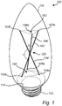
- the SSL lamp 100 comprises three elongated light emitting structures 102, 104, 106. All three light emitting structures 102, 104, 106 are elongated in the sense that their length exceeds three times their width.
- the light emitting structures 102, 104, 106 are arranged such that their lower ends 102a, 104a, 106a, defines a polygon 150, first polygon 150, in form of a triangle. In other words, a triangle is defined by connecting the respective ends 102a, 104a, 106a by straight lines, as shown in phantom in Fig. 1 .
- each of the light emitting structures 102, 104, 106 are arranged in vicinity of each other such that the three light emitting structures 102, 104, 106 crosses each other.
- a common neck 120 is formed where the three light emitting structures 102, 104, 106 crosses each other. As can be seen in Fig. 1 , the respective elongated light emitting structures 102, 104, 106 crosses each other in an angled fashion at the common neck 120.
- the elongated light emitting structures 102 and 104 crosses each other defining two angles, namely angle ⁇ and angle ⁇ '.
- Angle ⁇ and angle ⁇ ' together amount to 180 degrees.
- the elongated light emitting structures 102 and 104 crosses each other such that the smallest angle, in the depicted SSL lamp 100 angle ⁇ ', exceeds 30 degrees. Also the angle ⁇ exceeds 30 degrees. In order for the smallest angle of ⁇ and ⁇ ' to exceed 30 degrees the other angle of ⁇ and ⁇ ' cannot exceed 150 degrees as the sum of ⁇ and ⁇ ' is 180 degrees. Any angle of ⁇ and ⁇ ' may be the smallest angle. It is to be understood that corresponding angles are defined where each of the elongated light emitting structures 102, 104, 106 crosses each other, although not explicitly indicated in Fig. 1 .
- the light emitting structures 102, 104, 106 are arranged such that their upper ends 102b, 104b, 106b, defines another polygon 152, second polygon 152, also in form of a triangle. In other words, the light emitting structures 102, 104, 106 are arranged in a tripod configuration.
- the polygons 150, 152 are of equal shape, although being rotated relative to each other. Moreover, the polygons 150, 152 are of equal size in the depicted SSL lamp 100 of Fig. 1 .
- the polygons 150, 152 are of equal size since the respective light emitting structures 102, 104, 106 crosses each other at a respective center with respect to a longitudinal direction thereof. Further, the light emitting structures 102, 104, 106 are arranged with a corresponding angle with respect to a normal direction of the polygon 150. By crossing the respective light emitting structures 102, 104, 106 at different locations, polygons 150, 152 of different sizes may be achieved. In other words, other ratios between the sizes of the respective polygons 150, 152 may be achieved. Further, the polygons 150, 152 may be tilted with respect to each other.
- the three light emitting structures 102, 104, 106 are active light emitting structures in form of elongated LED filaments 102, 104, 106. Light is thus generated in and emitted from all three light emitting structures 102, 104, 106. All three light emitting structures 102, 104, 106 are electrically indirectly connected to the socket 112 via a driver, not shown.
- the socket 112 is used for attaching the SSL lamp 100 to a corresponding fitting, not shown.
- the elongated LED filaments 102, 104, 106 are mechanically fixed with respect to the socket 112.
- Various techniques and fixing elements may be used to fix the elongated LED filaments 102, 104, 106 with respect to the socket 112 as is known in the art.
- the elongated LED filaments 102, 104, 106 are arranged in a transparent bulb 110.
- the transparent bulb 110 encloses the elongated LED filaments 102, 104, 106.
- the SSL lamp 100 will resemble the appearance of a conventional incandescent lamp.
- the bulb 110 may protect the commonly delicate elongated LED filaments 102, 104, 106 from being brought into contact with external objects, which otherwise may damage the elongated LED filaments 102, 104, 106.
- handling of the SSL lamp 100 may be simplified and the risk of electrical chock may be reduced by employing a bulb 110.
- the bulb 110 is at its lower portion employed with an opening 114 through which the elongated LED filaments 102, 104, 106 may be inserted, before the opening 114 is sealed off by the socket 112.
- the opening 114 has a shape and size, such that the elongated LED filaments 102, 104, 106 may be arranged in their intended positions and electrically connected to the socket 112 and each other, before being inserted into the bulb 110.
- the polygons 150 and 152 fit through the opening 114.
- the LED filaments 102, 104, 106 may be indirectly connected to the socket 112 via a driver, not shown.
- the elongated LED filaments 102, 104, 106 of Fig. 1 are all of the same type meaning for instance that they are of equal size and shape, are emitting the same amount of light in terms of light flux, are emitting light having the same color temperature and color distribution. It is however to be noted that different types of elongated LED filaments 102, 104, 106 may be used in the same SSL lamp 100. By using different types of elongated LED filaments 102, 104, 106, the appearance and light distribution of the SSL lamp 100 may thus be tailored. For instance, elongated LED filaments 102, 104, 106, having different lengths and shapes, emitting different amounts of light of different color temperature may be used as an example. Moreover, elongated LED filaments 102, 104, 106 of different colors may be used. Furthermore, light emitting structures comprising solid state lasers may be used as an alternative to elongated LED filaments 102, 104, 106.
- the SSL lamp 100 comprises four elongated light emitting structures 102, 104, 106, 108. All four light emitting structures 102, 104, 106, 108 are elongated in the sense that their length exceeds three times their width.
- the light emitting structures 102, 104, 106, 108 are arranged such that their lower ends 102a, 104a, 106a, 108a defines a polygon 150, first polygon 150, in form of a rectangle.
- a rectangle is defined by connecting the respective ends 102a, 104a, 106a, 108a by straight lines, as shown in phantom in Fig. 2 .
- a central portion of each of the light emitting structures 102, 104, 106, 108 are arranged in vicinity of each other such that the four light emitting structures 102, 104, 106, 108 crosses each other.
- a common neck 120 is formed where the four light emitting structures 102, 104, 106, 108 crosses each other. As can be seen in Fig. 2 , the respective elongated light emitting structures 102, 104, 106, 108 crosses each other in an angled fashion at the common neck 120.
- the elongated light emitting structures 102 and 104 crosses each other defining two angles, namely angle ⁇ and angle ⁇ '.
- Angle ⁇ and angle ⁇ ' together amount to 180 degrees.
- the elongated light emitting structures 102 and 104 crosses each other such that the smallest angle, in the depicted SSL lamp 100, angle ⁇ ', exceeds 30 degrees. Also the angle ⁇ exceeds 30 degrees. In order for the smallest angle of ⁇ and ⁇ ' to exceed 30 degrees the other angle of ⁇ and ⁇ ' cannot exceed 150 degrees as the sum of ⁇ and ⁇ ' is 180 degrees. Any angle of ⁇ and ⁇ ' may be the smallest angle. It is to be understood that corresponding angles are defined where each of the elongated LED filaments 102, 104, 106, 108 crosses each other, although not explicitly indicated in Fig. 2 .
- the light emitting structures 102, 104, 106, 108 are arranged such that their upper ends 102b, 104b, 106b, 108b define another polygon 152, second polygon 152, also in form of a rectangle.
- the light emitting structures 102, 104, 106, 108 are arranged in a quadrupod configuration.
- the polygons 150, 152 are of equal shape, although being rotated relative to each other. Moreover, the polygons 150, 152 are of equal size in the depicted SSL lamp of Fig. 2 .
- the polygons 150, 152 are of equal size since the respective light emitting structures 102, 104, 106, 108 crosses each other at a respective center with respect to a longitudinal direction thereof. By crossing the respective light emitting structures 102, 104, 106, 108 at different locations, polygons of different sizes may be achieved, as described above in conjunction with Fig. 1 . Further, the polygons 150, 152 may be tilted with respect to each other.
- the four light emitting structures 102, 104, 106, 108 are of two different kinds. More specifically, the light emitting structures 102, 108 are active light emitting structures in form of elongated LED filaments 102, 108 whereas light emitting structures 104, 106 are passive light emitting structures in form of elongated light scattering features 104, 106.
- the elongated light scattering features 104, 106 are formed of rod shaped elements of a translucent material having a rough surface for scattering of light.
- Light is thus generated in and emitted from the light emitting structures 102, 108 whereas no light is generated in the light emitting structures 104, 106.
- Light generated and emitted by the LED filaments 102, 108 is however impinging on the light scattering features 104, 106.
- the light impinging on the light scattering features 104, 106 is thus scattered by and conducted within the light scattering features 104, 106. In other words, light will be emitted from the light scattering features 104, 106.
- the active light emitting structures 102, 108 are indirectly electrically connected to the socket 112 via a driver, not shown, whereas the passive light emitting structures 104, 106 are not electrically connected to the socket 112.
- the elongated light emitting structures 102, 104, 106, 108 are mechanically fixed with respect to the socket 112.
- Various techniques and fixing elements may be used to fix the elongated light emitting structures 102, 104, 106, 108 with respect to the socket 112 as described above in conjunction with Fig. 1 .
- the elongated LED filaments 102, 108 and the light scattering features 104, 106 of Fig. 2 are arranged in a transparent bulb 110, similarly to what has been described above in conjunction with Fig. 1 .
- the bulb 110 of Fig. 2 is at its lower portion employed with an opening 114 through which the elongated LED filaments 102, 108 and the light scattering features 104, 106 may be inserted, before the opening 114 is sealed off by the socket 112.
- the polygons 150, 152 fits through the opening 114.
- the elongated LED filaments 102, 108 of Fig. 2 are of the same type. However, LED filaments 102, 108 of different types may be used as described in conjunction with Fig. 1 above.
- the light scattering features 104, 106 of Fig. 2 are of the same type. However, light scattering features 104, 106 of different types may be used. For instance, the size and shape of the light scattering features may be varied. Moreover, the type of light scattering features may be varied.
- the number of elongated light emitting structures 102, 104, 106, 108 may be varied, in fact any number equal to or greater than three may be used, such as 6, 10 or 23 just to give a few non-limiting examples.
- the distribution between active light emitting structures and passive light emitting structures among the light emitting structures 102, 104, 106, 108 may be varied. However, in practice at least one of the elongated light emitting structures 102, 104, 106, 108 will have to be an active light emitting structure, or no light will be generated by the SSL lamp 100.
- one active light emitting structure such as a LED filament
- one passive light emitting structure such as light scattering feature, may be used with a plurality of active light emitting structures.
- any number of active light emitting structures may be used with any number of passive light emitting structures, as long as the total number of light emitting structures 102, 104, 106, 108 is equal to or greater than three and at least one light emitting structure is active.
- the SSL lamp 100 of Fig. 3 comprises three elongated light emitting structures 102, 104, 106, just like the SSL lamp 100 of Fig. 1 .
- the three elongated light emitting structures 102, 104, 106 of Fig. 3 . are however arranged differently as compared to the three elongated light emitting structures 102, 104, 106 of Fig. 1 .
- the three elongated light emitting structures 102, 104, 106 are not symmetrically arranged.
- the three elongated light emitting structures 102, 104, 106 are not of equal type.
- the light emitting structure 104 is longer than the light emitting structures 102, 106.
- the light emitting structures 102, 104, 106 are arranged such that their lower ends 102a, 104a, 106a, defines a polygon 150, first polygon 150, in form of a triangle, and their upper ends 102b, 104b, 106b, defines a polygon 152, second polygon 152, in form of a triangle.
- the light emitting structures 102, 104, 106 are arranged in what may be referred to as a tilted tripod configuration.
- the polygons 150, 152 are not of equal shape or size and are being rotated relative to each other. Polygon 150 is smaller than polygon 152.
- first polygon 150 and the second polygon 152 are slightly tilted with respect to each other. In other words, respective planes defined by the first polygon 150 and the second polygon 152 are not parallel. The first polygon 150 and the second polygon 152 may be tilted with any angle with respect to each other.
- each of the light emitting structures 102, 104, 106 are arranged in vicinity of each other such that the three light emitting structures 102, 104, 106 crosses each other.
- the three light emitting structures 102, 104, 106 crosses each other at a smallest angle of at least 30 degrees as explained above in conjunction with Fig. 1 .
- a common neck 120 is formed where the three light emitting structures 102, 104, 106 crosses each other. As can be seen in Fig. 3 , the respective elongated light emitting structures 102, 104, 106 crosses each other in an angled fashion at the common neck 120.
- the elongated light emitting structures 102, 104, 106 are arranged in a transparent bulb 110 employed with an opening 114 as described above in conjunction with Fig. 1 . Further, a socket 112 is provided as described above in conjunction with Fig. 1 .
- the present invention has been exemplified by describing a limited number of embodiments. It is however to be understood that a large number of embodiments and variations may easily be effected by combining what is described for the respective embodiments.
- the arrangement of the elongated light emitting structures 102, 104, 106, 108 may be greatly varied irrespective of the general design of the SSL lamp 100 and the bulb 110 used therein. It is to be understood that the shape and size of the bulb 110 and socket 112 may be varied depending on specific needs. Moreover, the bulb 110 and/or socket 112 may be omitted.
- the shape, size, light flux, color temperature, etcetera of the elongated active light emitting features 102, 104, 106, 108 may be varied without departing from the scope of the present inventive concept.
- the shape, size, extension, orientation, type, opacity, color, width, length etcetera of the passive light emitting features 104, 106 may be varied without departing from the scope of the present inventive concept.
- the physical dimensions of the SSL lamp 100 may be varied without departing from the scope of the present application. This allows for that the general inventive concept may be used in number of retrofit applications as well as in tailor-made specific applications.
Landscapes
- Engineering & Computer Science (AREA)
- Physics & Mathematics (AREA)
- Microelectronics & Electronic Packaging (AREA)
- Optics & Photonics (AREA)
- General Engineering & Computer Science (AREA)
- Non-Portable Lighting Devices Or Systems Thereof (AREA)
- Arrangement Of Elements, Cooling, Sealing, Or The Like Of Lighting Devices (AREA)
Claims (13)
- SSL-Lampe (100), die Folgendes umfasst:drei oder mehrere längliche Licht emittierende Strukturen (102, 104, 106, 108), wobei ein jeweiliges erstes Ende (102a, 104a, 106a, 108a) jeder der drei oder mehreren länglichen Licht emittierenden Strukturen (102, 104, 106, 108) angeordnet ist, sodass sie ein erstes Vieleck (150) definieren, undwobei ein Abschnitt jeder der drei oder mehreren länglichen Licht emittierenden Strukturen (102, 104, 106, 108) in der Nähe jeder anderen angeordnet ist, sodass die drei oder mehreren länglichen Licht emittierenden Strukturen (102, 104, 106, 108) einander an einem kleinsten Winkel (α, α') von mindestens 30 Grad kreuzen, wodurch ein gemeinsamer Hals (120) gebildet wird, dadurch gekennzeichnet, dass ein jeweiliges zweites Ende (102b, 104b, 106b, 108b) jeder der drei oder mehreren länglichen Licht emittierenden Strukturen (102, 104, 106, 108) angeordnet ist, dass sie ein zweites Vieleck (152) definieren, wobei das erste und das zweite Vieleck (150, 152) zueinander gedreht sind.
- SSL-Lampe (100) nach Anspruch 1, wobei mindestens eine der drei oder mehreren Licht emittierenden Strukturen (102, 104, 106, 108) eine aktive Licht emittierende Struktur in der Form eines länglichen LED-Fadens (102, 104, 106, 108) ist.
- SSL-Lampe (100) nach Anspruch 1 oder 2, wobei mindestens eine der drei oder mehreren länglichen Licht emittierenden Strukturen (102, 104, 106, 108) eine aktive Licht emittierende Struktur in der Form einer länglichen Licht emittierenden Struktur, die einen Halbleiterlaser umfasst, ist.
- SSL-Lampe (100) nach einem der Ansprüche 1 bis 3, wobei mindestens eine der drei oder mehreren Licht emittierenden Strukturen (102, 104, 106, 108) eine passive Licht emittierende Struktur in der Form eines länglichen Licht streuenden Merkmals (104, 106) ist.
- SSL-Lampe (100) nach Anspruch 1, wobei die drei oder mehreren länglichen Licht emittierenden Strukturen (102, 104, 106, 108) aktive Licht emittierende Strukturen in der Form länglicher LED-Fäden (102, 104, 106, 108) sind.
- SSL-Lampe (100) nach einem der Ansprüche 1 bis 5, wobei das erste Vieleck (150) und das zweite Vieleck (152) gleiche Form aufweisen.
- SSL-Lampe (100) nach einem der Ansprüche 1 bis 6, wobei das erste Vieleck (150) und das zweite Vieleck (152) gleiche Größe aufweisen.
- SSL-Lampe (100) nach einem der Ansprüche 1 bis 7, wobei jede der drei oder mehreren länglichen Licht emittierenden Strukturen (102, 104, 106, 108) mit einem entsprechenden Winkel zu einer senkrechten Richtung des ersten Vielecks angeordnet ist.
- SSL-Lampe (100) nach einem der Ansprüche 1 bis 8, die drei längliche Licht emittierende Strukturen (102, 104, 106), die in einer Dreibeinkonfiguration angeordnet sind, umfasst.
- SSL-Lampe (100) nach einem der Ansprüche 1 bis 8, die vier längliche Licht emittierende Strukturen (102, 104, 106, 108), die in einer Vierbeinkonfiguration angeordnet sind, umfasst.
- SSL-Lampe (100) nach einem der Ansprüche 1 bis 10, die weiter einen durchsichtigen Kolben (110) umfasst, der konfiguriert ist, um die drei oder mehreren länglichen Licht emittierenden Strukturen (102, 104, 106, 108) mindestens teilweise zu umschließen.
- SSL-Lampe (100) nach Anspruch 11, wobei der durchsichtige Kolben (110) eine Öffnung (114), durch die das erste Vieleck (150) passt, umfasst.
- SSL-Lampe (100) nach Anspruch 11 oder 12, wobei der durchsichtige Kolben (100) eine Öffnung (114), durch die das zweite Vieleck (152) passt, umfasst.
Priority Applications (3)
| Application Number | Priority Date | Filing Date | Title |
|---|---|---|---|
| SI201730234T SI3500792T1 (sl) | 2017-01-05 | 2017-12-18 | SSL žarnica |
| EP20151415.5A EP3671010B1 (de) | 2017-01-05 | 2017-12-18 | Ssi-lampe |
| PL17816839T PL3500792T3 (pl) | 2017-01-05 | 2017-12-18 | Lampa ssl |
Applications Claiming Priority (2)
| Application Number | Priority Date | Filing Date | Title |
|---|---|---|---|
| EP17150411 | 2017-01-05 | ||
| PCT/EP2017/083241 WO2018127391A1 (en) | 2017-01-05 | 2017-12-18 | Ssl lamp |
Related Child Applications (1)
| Application Number | Title | Priority Date | Filing Date |
|---|---|---|---|
| EP20151415.5A Division EP3671010B1 (de) | 2017-01-05 | 2017-12-18 | Ssi-lampe |
Publications (2)
| Publication Number | Publication Date |
|---|---|
| EP3500792A1 EP3500792A1 (de) | 2019-06-26 |
| EP3500792B1 true EP3500792B1 (de) | 2020-02-12 |
Family
ID=57737675
Family Applications (2)
| Application Number | Title | Priority Date | Filing Date |
|---|---|---|---|
| EP17816839.9A Active EP3500792B1 (de) | 2017-01-05 | 2017-12-18 | Ssl-lampe |
| EP20151415.5A Active EP3671010B1 (de) | 2017-01-05 | 2017-12-18 | Ssi-lampe |
Family Applications After (1)
| Application Number | Title | Priority Date | Filing Date |
|---|---|---|---|
| EP20151415.5A Active EP3671010B1 (de) | 2017-01-05 | 2017-12-18 | Ssi-lampe |
Country Status (11)
| Country | Link |
|---|---|
| US (1) | US10670194B2 (de) |
| EP (2) | EP3500792B1 (de) |
| JP (2) | JP6878599B2 (de) |
| CN (1) | CN109844399A (de) |
| DK (1) | DK3500792T3 (de) |
| ES (2) | ES2787025T3 (de) |
| HU (1) | HUE057550T2 (de) |
| PL (1) | PL3500792T3 (de) |
| PT (1) | PT3500792T (de) |
| SI (1) | SI3500792T1 (de) |
| WO (1) | WO2018127391A1 (de) |
Families Citing this family (9)
| Publication number | Priority date | Publication date | Assignee | Title |
|---|---|---|---|---|
| US10330263B2 (en) * | 2017-02-26 | 2019-06-25 | Leedarson America Inc. | Light apparatus |
| JP7185066B2 (ja) * | 2019-02-28 | 2022-12-06 | シグニファイ ホールディング ビー ヴィ | 反射器を有するフィラメントランプ |
| EP4038311B1 (de) * | 2019-10-01 | 2023-02-15 | Signify Holding B.V. | Led-filament-anordnung |
| CN114556014B (zh) * | 2019-10-03 | 2024-08-23 | 昕诺飞控股有限公司 | Led灯丝照明设备 |
| CN114630986B (zh) * | 2019-10-31 | 2024-10-22 | 昕诺飞控股有限公司 | Led灯丝装置 |
| US12123555B2 (en) | 2020-01-02 | 2024-10-22 | Signify Holding, B.V. | LED filament arrangement |
| ES2967337T3 (es) * | 2020-04-16 | 2024-04-29 | Signify Holding Bv | Lámpara de filamento led controlable por temperatura de color que proporciona una calidad de luz mejorada |
| WO2023139095A1 (en) * | 2022-01-20 | 2023-07-27 | Signify Holding B.V. | Conductor element for a filament lamp |
| EP4476477B1 (de) | 2022-02-08 | 2025-11-26 | Signify Holding B.V. | Kühlkörper mit einem geschlossenen schlitz zum pumpen eines zylindrischen phosphorkörpers |
Family Cites Families (21)
| Publication number | Priority date | Publication date | Assignee | Title |
|---|---|---|---|---|
| WO1991003831A1 (fr) * | 1989-08-29 | 1991-03-21 | Olgerd Ivanovich Babich | Dispositif de chauffage de cathode pour tube a rayons electroniques |
| EP2411726A1 (de) | 2009-03-23 | 2012-02-01 | EldoLAB Holding B.V. | Einen lichtleiter mit einer ersten und einer zweiten streufläche umfassende led-lampe |
| DE102011007123B4 (de) * | 2011-04-11 | 2022-02-17 | Osram Gmbh | Halbleiter-Glühlampen-Retrofitlampe |
| WO2013099074A1 (ja) | 2011-12-27 | 2013-07-04 | パナソニック株式会社 | ランプおよびこれを用いた照明器具 |
| TW201407100A (zh) | 2012-08-13 | 2014-02-16 | 新世紀光電股份有限公司 | 發光裝置 |
| US9677738B2 (en) | 2013-03-15 | 2017-06-13 | 1947796 Ontario Inc. | Optical device and system for solid-state lighting |
| CN103712105A (zh) | 2013-12-26 | 2014-04-09 | 四川柏狮光电技术有限公司 | 一种扭纹状灯丝排布的全配光型led球泡灯 |
| CN203797384U (zh) * | 2013-12-26 | 2014-08-27 | 四川柏狮光电技术有限公司 | 旋转灯丝led球泡灯 |
| EP3019787B1 (de) | 2014-03-13 | 2017-09-13 | Philips Lighting Holding B.V. | Faden für beleuchtungsvorrichtung |
| CN203848062U (zh) * | 2014-05-23 | 2014-09-24 | 四川海金汇光电有限公司 | 伞形led灯丝 |
| CN104676322B (zh) | 2015-01-20 | 2017-01-04 | 浙江凯耀照明股份有限公司 | 提高发光强度的led灯丝排列结构及led灯丝灯 |
| CN204437756U (zh) * | 2015-01-20 | 2015-07-01 | 浙江凯耀照明股份有限公司 | 提高发光强度的led灯丝排列结构及led灯丝灯 |
| EP3276247B1 (de) * | 2015-03-23 | 2019-09-18 | Shandong Prosperous Star Optoelectronics Co., Ltd. | Led-leuchtdraht und led-leuchtdrahtbeleuchtungslampe dafür |
| CN204693112U (zh) | 2015-06-09 | 2015-10-07 | 杭州时代照明电器有限公司 | 一种led灯泡 |
| CN204717433U (zh) * | 2015-06-24 | 2015-10-21 | 立达信绿色照明股份有限公司 | Led灯丝灯 |
| CN205065343U (zh) * | 2015-11-05 | 2016-03-02 | 中国科学院光电技术研究所光学元件厂 | 一种三棱形led灯丝灯 |
| CN205606241U (zh) * | 2016-01-06 | 2016-09-28 | 山东晶泰星光电科技有限公司 | 一种全配光型led灯 |
| CN205535146U (zh) * | 2016-01-27 | 2016-08-31 | 新和(绍兴)绿色照明有限公司 | 一种led灯丝条球泡灯 |
| CN105927872A (zh) * | 2016-04-29 | 2016-09-07 | 横店集团得邦照明股份有限公司 | 一种led全方向灯丝灯及其实现方法 |
| JP3205545U (ja) | 2016-05-20 | 2016-07-28 | 株式会社エス・ティー・イー | Led電球及びこれが具備する口金カバー |
| CN106015986A (zh) * | 2016-07-05 | 2016-10-12 | 河北小旋风照明科技开发有限公司 | 交叉型led灯丝灯 |
-
2017
- 2017-12-18 EP EP17816839.9A patent/EP3500792B1/de active Active
- 2017-12-18 PT PT178168399T patent/PT3500792T/pt unknown
- 2017-12-18 ES ES17816839T patent/ES2787025T3/es active Active
- 2017-12-18 PL PL17816839T patent/PL3500792T3/pl unknown
- 2017-12-18 CN CN201780061531.3A patent/CN109844399A/zh active Pending
- 2017-12-18 US US16/336,139 patent/US10670194B2/en active Active
- 2017-12-18 DK DK17816839.9T patent/DK3500792T3/da active
- 2017-12-18 HU HUE20151415A patent/HUE057550T2/hu unknown
- 2017-12-18 ES ES20151415T patent/ES2905134T3/es active Active
- 2017-12-18 JP JP2019536481A patent/JP6878599B2/ja active Active
- 2017-12-18 WO PCT/EP2017/083241 patent/WO2018127391A1/en not_active Ceased
- 2017-12-18 EP EP20151415.5A patent/EP3671010B1/de active Active
- 2017-12-18 SI SI201730234T patent/SI3500792T1/sl unknown
-
2021
- 2021-04-28 JP JP2021075571A patent/JP7071572B2/ja active Active
Non-Patent Citations (1)
| Title |
|---|
| None * |
Also Published As
| Publication number | Publication date |
|---|---|
| JP2020503655A (ja) | 2020-01-30 |
| EP3671010A1 (de) | 2020-06-24 |
| HUE057550T2 (hu) | 2022-05-28 |
| WO2018127391A1 (en) | 2018-07-12 |
| PL3500792T3 (pl) | 2020-07-27 |
| DK3500792T3 (da) | 2020-04-06 |
| CN109844399A (zh) | 2019-06-04 |
| SI3500792T1 (sl) | 2020-07-31 |
| JP7071572B2 (ja) | 2022-05-19 |
| ES2905134T3 (es) | 2022-04-07 |
| PT3500792T (pt) | 2020-05-14 |
| JP2021132037A (ja) | 2021-09-09 |
| EP3500792A1 (de) | 2019-06-26 |
| US10670194B2 (en) | 2020-06-02 |
| US20190316740A1 (en) | 2019-10-17 |
| ES2787025T3 (es) | 2020-10-14 |
| JP6878599B2 (ja) | 2021-05-26 |
| EP3671010B1 (de) | 2021-11-10 |
Similar Documents
| Publication | Publication Date | Title |
|---|---|---|
| EP3500792B1 (de) | Ssl-lampe | |
| US11448369B2 (en) | Light emitting device | |
| US10663119B2 (en) | LED filament for omnidirectional lamp | |
| ES2550263T3 (es) | Fuente de luz con ledes, guía de luz y reflector | |
| EP4004431B1 (de) | Lichtemittierende vorrichtung | |
| US10816145B2 (en) | Light emitting diode filament light source | |
| US20170234519A1 (en) | Led lamp unit | |
| JP7155458B1 (ja) | 照明デバイス | |
| EP3155312B1 (de) | Beleuchtungsvorrichtung | |
| JP6497501B2 (ja) | 発光装置 | |
| EP4085218B1 (de) | Led-filament-anordnung | |
| JP6997912B1 (ja) | Ledフィラメント構成 | |
| US20230280002A1 (en) | A light emitting device |
Legal Events
| Date | Code | Title | Description |
|---|---|---|---|
| STAA | Information on the status of an ep patent application or granted ep patent |
Free format text: STATUS: UNKNOWN |
|
| STAA | Information on the status of an ep patent application or granted ep patent |
Free format text: STATUS: THE INTERNATIONAL PUBLICATION HAS BEEN MADE |
|
| PUAI | Public reference made under article 153(3) epc to a published international application that has entered the european phase |
Free format text: ORIGINAL CODE: 0009012 |
|
| STAA | Information on the status of an ep patent application or granted ep patent |
Free format text: STATUS: REQUEST FOR EXAMINATION WAS MADE |
|
| 17P | Request for examination filed |
Effective date: 20190322 |
|
| AK | Designated contracting states |
Kind code of ref document: A1 Designated state(s): AL AT BE BG CH CY CZ DE DK EE ES FI FR GB GR HR HU IE IS IT LI LT LU LV MC MK MT NL NO PL PT RO RS SE SI SK SM TR |
|
| AX | Request for extension of the european patent |
Extension state: BA ME |
|
| GRAP | Despatch of communication of intention to grant a patent |
Free format text: ORIGINAL CODE: EPIDOSNIGR1 |
|
| STAA | Information on the status of an ep patent application or granted ep patent |
Free format text: STATUS: GRANT OF PATENT IS INTENDED |
|
| DAV | Request for validation of the european patent (deleted) | ||
| INTG | Intention to grant announced |
Effective date: 20190902 |
|
| GRAS | Grant fee paid |
Free format text: ORIGINAL CODE: EPIDOSNIGR3 |
|
| GRAA | (expected) grant |
Free format text: ORIGINAL CODE: 0009210 |
|
| STAA | Information on the status of an ep patent application or granted ep patent |
Free format text: STATUS: THE PATENT HAS BEEN GRANTED |
|
| AK | Designated contracting states |
Kind code of ref document: B1 Designated state(s): AL AT BE BG CH CY CZ DE DK EE ES FI FR GB GR HR HU IE IS IT LI LT LU LV MC MK MT NL NO PL PT RO RS SE SI SK SM TR |
|
| DAX | Request for extension of the european patent (deleted) | ||
| REG | Reference to a national code |
Ref country code: GB Ref legal event code: FG4D |
|
| REG | Reference to a national code |
Ref country code: CH Ref legal event code: EP |
|
| REG | Reference to a national code |
Ref country code: AT Ref legal event code: REF Ref document number: 1232564 Country of ref document: AT Kind code of ref document: T Effective date: 20200215 |
|
| REG | Reference to a national code |
Ref country code: IE Ref legal event code: FG4D |
|
| REG | Reference to a national code |
Ref country code: DE Ref legal event code: R096 Ref document number: 602017011789 Country of ref document: DE |
|
| REG | Reference to a national code |
Ref country code: DK Ref legal event code: T3 Effective date: 20200403 |
|
| REG | Reference to a national code |
Ref country code: CH Ref legal event code: NV Representative=s name: VALIPAT S.A. C/O BOVARD SA NEUCHATEL, CH |
|
| REG | Reference to a national code |
Ref country code: NL Ref legal event code: FP |
|
| REG | Reference to a national code |
Ref country code: FI Ref legal event code: FGE |
|
| REG | Reference to a national code |
Ref country code: PT Ref legal event code: SC4A Ref document number: 3500792 Country of ref document: PT Date of ref document: 20200514 Kind code of ref document: T Free format text: AVAILABILITY OF NATIONAL TRANSLATION Effective date: 20200506 |
|
| REG | Reference to a national code |
Ref country code: NO Ref legal event code: T2 Effective date: 20200212 |
|
| REG | Reference to a national code |
Ref country code: SE Ref legal event code: TRGR |
|
| PG25 | Lapsed in a contracting state [announced via postgrant information from national office to epo] |
Ref country code: RS Free format text: LAPSE BECAUSE OF FAILURE TO SUBMIT A TRANSLATION OF THE DESCRIPTION OR TO PAY THE FEE WITHIN THE PRESCRIBED TIME-LIMIT Effective date: 20200212 |
|
| REG | Reference to a national code |
Ref country code: LT Ref legal event code: MG4D |
|
| PG25 | Lapsed in a contracting state [announced via postgrant information from national office to epo] |
Ref country code: LV Free format text: LAPSE BECAUSE OF FAILURE TO SUBMIT A TRANSLATION OF THE DESCRIPTION OR TO PAY THE FEE WITHIN THE PRESCRIBED TIME-LIMIT Effective date: 20200212 Ref country code: HR Free format text: LAPSE BECAUSE OF FAILURE TO SUBMIT A TRANSLATION OF THE DESCRIPTION OR TO PAY THE FEE WITHIN THE PRESCRIBED TIME-LIMIT Effective date: 20200212 Ref country code: GR Free format text: LAPSE BECAUSE OF FAILURE TO SUBMIT A TRANSLATION OF THE DESCRIPTION OR TO PAY THE FEE WITHIN THE PRESCRIBED TIME-LIMIT Effective date: 20200513 Ref country code: IS Free format text: LAPSE BECAUSE OF FAILURE TO SUBMIT A TRANSLATION OF THE DESCRIPTION OR TO PAY THE FEE WITHIN THE PRESCRIBED TIME-LIMIT Effective date: 20200612 Ref country code: BG Free format text: LAPSE BECAUSE OF FAILURE TO SUBMIT A TRANSLATION OF THE DESCRIPTION OR TO PAY THE FEE WITHIN THE PRESCRIBED TIME-LIMIT Effective date: 20200512 |
|
| REG | Reference to a national code |
Ref country code: ES Ref legal event code: FG2A Ref document number: 2787025 Country of ref document: ES Kind code of ref document: T3 Effective date: 20201014 |
|
| PG25 | Lapsed in a contracting state [announced via postgrant information from national office to epo] |
Ref country code: SK Free format text: LAPSE BECAUSE OF FAILURE TO SUBMIT A TRANSLATION OF THE DESCRIPTION OR TO PAY THE FEE WITHIN THE PRESCRIBED TIME-LIMIT Effective date: 20200212 Ref country code: RO Free format text: LAPSE BECAUSE OF FAILURE TO SUBMIT A TRANSLATION OF THE DESCRIPTION OR TO PAY THE FEE WITHIN THE PRESCRIBED TIME-LIMIT Effective date: 20200212 Ref country code: LT Free format text: LAPSE BECAUSE OF FAILURE TO SUBMIT A TRANSLATION OF THE DESCRIPTION OR TO PAY THE FEE WITHIN THE PRESCRIBED TIME-LIMIT Effective date: 20200212 Ref country code: CZ Free format text: LAPSE BECAUSE OF FAILURE TO SUBMIT A TRANSLATION OF THE DESCRIPTION OR TO PAY THE FEE WITHIN THE PRESCRIBED TIME-LIMIT Effective date: 20200212 Ref country code: EE Free format text: LAPSE BECAUSE OF FAILURE TO SUBMIT A TRANSLATION OF THE DESCRIPTION OR TO PAY THE FEE WITHIN THE PRESCRIBED TIME-LIMIT Effective date: 20200212 Ref country code: SM Free format text: LAPSE BECAUSE OF FAILURE TO SUBMIT A TRANSLATION OF THE DESCRIPTION OR TO PAY THE FEE WITHIN THE PRESCRIBED TIME-LIMIT Effective date: 20200212 |
|
| REG | Reference to a national code |
Ref country code: DE Ref legal event code: R097 Ref document number: 602017011789 Country of ref document: DE |
|
| PLBE | No opposition filed within time limit |
Free format text: ORIGINAL CODE: 0009261 |
|
| STAA | Information on the status of an ep patent application or granted ep patent |
Free format text: STATUS: NO OPPOSITION FILED WITHIN TIME LIMIT |
|
| 26N | No opposition filed |
Effective date: 20201113 |
|
| PG25 | Lapsed in a contracting state [announced via postgrant information from national office to epo] |
Ref country code: MC Free format text: LAPSE BECAUSE OF FAILURE TO SUBMIT A TRANSLATION OF THE DESCRIPTION OR TO PAY THE FEE WITHIN THE PRESCRIBED TIME-LIMIT Effective date: 20200212 |
|
| PG25 | Lapsed in a contracting state [announced via postgrant information from national office to epo] |
Ref country code: LU Free format text: LAPSE BECAUSE OF NON-PAYMENT OF DUE FEES Effective date: 20201218 Ref country code: IE Free format text: LAPSE BECAUSE OF NON-PAYMENT OF DUE FEES Effective date: 20201218 |
|
| REG | Reference to a national code |
Ref country code: AT Ref legal event code: UEP Ref document number: 1232564 Country of ref document: AT Kind code of ref document: T Effective date: 20200212 |
|
| PG25 | Lapsed in a contracting state [announced via postgrant information from national office to epo] |
Ref country code: MT Free format text: LAPSE BECAUSE OF FAILURE TO SUBMIT A TRANSLATION OF THE DESCRIPTION OR TO PAY THE FEE WITHIN THE PRESCRIBED TIME-LIMIT Effective date: 20200212 Ref country code: CY Free format text: LAPSE BECAUSE OF FAILURE TO SUBMIT A TRANSLATION OF THE DESCRIPTION OR TO PAY THE FEE WITHIN THE PRESCRIBED TIME-LIMIT Effective date: 20200212 |
|
| PG25 | Lapsed in a contracting state [announced via postgrant information from national office to epo] |
Ref country code: MK Free format text: LAPSE BECAUSE OF FAILURE TO SUBMIT A TRANSLATION OF THE DESCRIPTION OR TO PAY THE FEE WITHIN THE PRESCRIBED TIME-LIMIT Effective date: 20200212 Ref country code: AL Free format text: LAPSE BECAUSE OF FAILURE TO SUBMIT A TRANSLATION OF THE DESCRIPTION OR TO PAY THE FEE WITHIN THE PRESCRIBED TIME-LIMIT Effective date: 20200212 |
|
| P01 | Opt-out of the competence of the unified patent court (upc) registered |
Effective date: 20230425 |
|
| PGFP | Annual fee paid to national office [announced via postgrant information from national office to epo] |
Ref country code: PT Payment date: 20251204 Year of fee payment: 9 |
|
| REG | Reference to a national code |
Ref country code: CH Ref legal event code: U11 Free format text: ST27 STATUS EVENT CODE: U-0-0-U10-U11 (AS PROVIDED BY THE NATIONAL OFFICE) Effective date: 20260101 |
|
| PGFP | Annual fee paid to national office [announced via postgrant information from national office to epo] |
Ref country code: GB Payment date: 20251223 Year of fee payment: 9 |
|
| PGFP | Annual fee paid to national office [announced via postgrant information from national office to epo] |
Ref country code: NO Payment date: 20251218 Year of fee payment: 9 |
|
| PGFP | Annual fee paid to national office [announced via postgrant information from national office to epo] |
Ref country code: AT Payment date: 20251218 Year of fee payment: 9 |
|
| PGFP | Annual fee paid to national office [announced via postgrant information from national office to epo] |
Ref country code: IT Payment date: 20251218 Year of fee payment: 9 Ref country code: FI Payment date: 20251222 Year of fee payment: 9 Ref country code: DK Payment date: 20251222 Year of fee payment: 9 |
|
| PGFP | Annual fee paid to national office [announced via postgrant information from national office to epo] |
Ref country code: NL Payment date: 20251222 Year of fee payment: 9 Ref country code: FR Payment date: 20251230 Year of fee payment: 9 |
|
| PGFP | Annual fee paid to national office [announced via postgrant information from national office to epo] |
Ref country code: TR Payment date: 20251205 Year of fee payment: 9 |
|
| PGFP | Annual fee paid to national office [announced via postgrant information from national office to epo] |
Ref country code: SE Payment date: 20251222 Year of fee payment: 9 |
|
| PGFP | Annual fee paid to national office [announced via postgrant information from national office to epo] |
Ref country code: PL Payment date: 20251208 Year of fee payment: 9 |
|
| PGFP | Annual fee paid to national office [announced via postgrant information from national office to epo] |
Ref country code: SI Payment date: 20251204 Year of fee payment: 9 |
|
| PGFP | Annual fee paid to national office [announced via postgrant information from national office to epo] |
Ref country code: ES Payment date: 20260122 Year of fee payment: 9 |
|
| PGFP | Annual fee paid to national office [announced via postgrant information from national office to epo] |
Ref country code: DE Payment date: 20260220 Year of fee payment: 9 |
|
| PGFP | Annual fee paid to national office [announced via postgrant information from national office to epo] |
Ref country code: BE Payment date: 20260109 Year of fee payment: 9 |
|
| PGFP | Annual fee paid to national office [announced via postgrant information from national office to epo] |
Ref country code: CH Payment date: 20260101 Year of fee payment: 9 |