EP3501079B1 - Procédé de fourniture d'une réserve temporaire dans un réseau d'alimentation en énergie électrique, programme d'ordinateur et onduleur commandé en courant - Google Patents
Procédé de fourniture d'une réserve temporaire dans un réseau d'alimentation en énergie électrique, programme d'ordinateur et onduleur commandé en courant Download PDFInfo
- Publication number
- EP3501079B1 EP3501079B1 EP17755469.8A EP17755469A EP3501079B1 EP 3501079 B1 EP3501079 B1 EP 3501079B1 EP 17755469 A EP17755469 A EP 17755469A EP 3501079 B1 EP3501079 B1 EP 3501079B1
- Authority
- EP
- European Patent Office
- Prior art keywords
- current
- inverter
- energy supply
- control loop
- supply grid
- Prior art date
- Legal status (The legal status is an assumption and is not a legal conclusion. Google has not performed a legal analysis and makes no representation as to the accuracy of the status listed.)
- Active
Links
Images

Classifications
-
- H—ELECTRICITY
- H02—GENERATION; CONVERSION OR DISTRIBUTION OF ELECTRIC POWER
- H02J—ELECTRIC POWER NETWORKS; CIRCUIT ARRANGEMENTS OR SYSTEMS FOR SUPPLYING OR DISTRIBUTING ELECTRIC POWER; SYSTEMS FOR STORING ELECTRIC ENERGY
- H02J3/00—Circuit arrangements for AC mains or AC distribution networks
- H02J3/38—Arrangements for feeding a single network from two or more generators or sources in parallel; Arrangements for feeding already energised networks from additional generators or sources in parallel
- H02J3/40—Synchronisation of generators for connection to a network or to another generator
-
- H—ELECTRICITY
- H02—GENERATION; CONVERSION OR DISTRIBUTION OF ELECTRIC POWER
- H02J—ELECTRIC POWER NETWORKS; CIRCUIT ARRANGEMENTS OR SYSTEMS FOR SUPPLYING OR DISTRIBUTING ELECTRIC POWER; SYSTEMS FOR STORING ELECTRIC ENERGY
- H02J3/00—Circuit arrangements for AC mains or AC distribution networks
- H02J3/28—Arrangements for balancing of the load in networks by storage of energy
Definitions
- the invention relates to a method for providing instantaneous reserve in an electrical power supply network by means of a current-impressing inverter according to claim 1.
- the invention also relates to a computer program for carrying out such a method and a current-impressing inverter for controlled output of alternating currents to an energy supply network.
- An instantaneous reserve is an instantaneous change in active power when feeding electrical energy into an energy supply network due to a frequency change and / or frequency gradient in the voltages of the energy supply network.
- a delay-free change in active power is understood to mean, in particular, tracking the active power to a desired value within a period of time whose duration is a maximum of 25% of the period duration of the specified mean setpoint frequency of the alternating voltages of the power supply network.
- Synchronous machines are mainly used in conventional power plants. These will become even more uneconomical due to the energy transition and will probably be replaced in the long term by decentralized, renewable energy sources that feed the electrical energy into the energy supply network via inverters.
- a method for providing instantaneous reserve in an electrical power supply network by means of a current-impressing inverter according to claim 1.
- a current regulator of the inverter is supplied directly or indirectly with an instantaneous reserve setpoint signal, which is generated by means of a PLL control loop, to which the measured AC voltages of the power supply network or signals transformed therefrom are supplied as input signals, the instantaneous reserve setpoint signal from a phase error signal of the PLL Control loop is generated.
- the invention has the advantage that an instantaneous reserve can now be provided in the electrical power supply network by means of a current-impressing inverter.
- the instantaneous reserve can be provided by the current-injecting inverter with relatively little technical effort.
- the invention can be implemented in existing, already installed systems in the inverter, for example by performing a software update there.
- the invention has the advantage that the frequency stability in the energy supply network can be improved in a simple and inexpensive manner and frequency gradients can be limited.
- the invention uses functions that can be easily implemented, such as a PLL control loop to which the measured AC voltages of the power supply network or signals transformed therefrom are fed as input signals.
- the essentially instantaneous change in active power which is required to provide the instantaneous reserve, can in particular be implemented in that the instantaneous reserve setpoint signal is generated from an internal variable in the PLL control loop, namely a phase error signal, and not from a conventional output variable of a PLL Control loop, such as frequency and / or phase position ⁇ .
- a PLL control loop (PLL - Phase-Locked-Loop), which is also referred to as a phase-locked loop, is a circuit that influences the phase position and the associated frequency of an oscillating input signal via a closed control loop in such a way that the phase deviation between an external difference signal and the oscillator or a signal derived therefrom is as constant as possible.
- a PLL control loop does not necessarily have to be used to control a phase position and / or frequency, but can also be used to measure a phase position and / or frequency in the sense of a clock recovery circuit.
- a PLL control loop is characterized in particular by its technically simple feasibility.
- the PLL control loop can be implemented by electrical and / or electronic circuit components, i.e. as an electronic circuit arrangement, and / or by software (computer program).
- the phase error signal is generated as an internal intermediate variable within the control loop of the PLL control loop. This has the advantage that the signal used for the instantaneous reserve setpoint signal, namely the phase error signal, is available essentially without delay.
- the phase error signal is generated without delay or with a delay time that is significantly less than the period of a specified mean setpoint frequency of the alternating voltages of the power supply network. In this way, an efficient instantaneous reserve can be provided.
- the PLL control loop determines the frequency and the phase position of the measured AC voltages of the power supply network and provides them as output signals. Accordingly, the PLL control loop does not serve as a control loop for controlling a frequency, but is used in the sense of a clock recovery circuit.
- the PLL control loop determines the frequency and the phase position of the measured alternating voltages of the energy supply network with a delay time that is at least as long as the period of a specified mean setpoint frequency of the alternating voltages of the energy supply network.
- the PLL control loop can, for example, be implemented with a measurement time constant in the order of magnitude of 100 milliseconds to 5 seconds, thus with relatively large values of the measurement time constants compared to 50 Hertz mains frequency.
- the instantaneous reserve setpoint signal is fed to a control block upstream of the current regulator, to which further input signals are fed, including at least setpoint signals of the network functions of the energy supply network, the control block combining the fed input signals into a resulting output signal, which is fed to the current regulator.
- useful network functions can also be included for the stable operation of the energy supply network, such as, for example, a frequency-dependent active power reduction or static voltage maintenance.
- a current-injecting inverter for the regulated delivery of alternating currents to an energy supply network, according to claim 7, wherein the inverter has a current control hardware with at least one current regulator, which is set up to regulate the output alternating currents to one or more current setpoints, wherein the inverter has a control device with at least one computer and at least one memory and a computer program according to the preceding claim is stored in the memory, the computer having access to the memory for executing the computer program.
- the invention can be implemented in software, i.e. by a computer program.
- the invention can also be implemented in whole or in part by hardware components.
- a current-injecting inverter for the controlled delivery of alternating currents to an energy supply network, according to claim 8, wherein the inverter has current control hardware with at least one current controller which is set up to control the output alternating currents to one or more current setpoints, wherein the inverter is set up to provide instantaneous reserve in the electrical power supply network by the current regulator being supplied directly or indirectly with an instantaneous reserve setpoint signal that is generated by means of a PLL control loop to which the measured AC voltages of the power supply network or signals transformed therefrom are supplied as input signals , where the Instantaneous reserve setpoint signal is generated from a phase error signal of the PLL control loop.
- the inverter can in particular be designed as an inverter of a battery storage system of a photovoltaic system and / or a wind power plant.
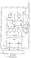
- FIG. 1 It will be according to Figure 1 assumed a three-phase power supply network 1.
- the alternating voltages of the three phases are recorded in a recording block 2, ie measured and transformed into a form customary in inverter technology, for example by means of a Clark transformation.
- the signals ⁇ and ⁇ formed in this way are made available by the detection block 2 to subsequent blocks.
- These subsequent blocks include a frequency acquisition block 3.
- the current frequency of the alternating voltages of the power supply network 1 is determined, for example by means of a fast PLL control loop that is operated as a clock recovery device.
- the effective value (RMS - Root Mean Square) of the recorded AC voltages is determined in an effective value determination block 4.
- an instantaneous reserve setpoint signal P mom is generated in a block 5 from a phase error signal of a PLL control loop implemented there. This is explained below using the Figure 2 explained in more detail.
- a frequency signal f is fed from block 3 to a block 6.
- An effective value signal RMS is fed from block 4 to block 6.
- certain network functions are implemented and executed, for example a frequency-dependent active power reduction and / or static voltage maintenance.
- output signals are generated which are fed to a block 7.
- the instantaneous reserve setpoint signal P mom from block 5 is also fed to block 7.
- the input signals supplied are combined.
- the input signals are prioritized with respect to the output signals emitted by block 7, and the input signals can also be limited to limit values. Furthermore, all or some of the input signals can be added.
- the block 7 generates two current components as output signals in the representation customary in energy supply technology, namely the longitudinal current i d and the transverse current i q , through which the phase currents are reproduced in rotor coordinates. These output signals from block 7 are fed to current control hardware 9 with an integrated current regulator 8.
- the current control hardware 9 is, for example, inverter hardware designed with semiconductor switches, which in turn is connected to the lines of the energy supply network 1.
- the inverter hardware 9 is also supplied with the electrical input energy to be converted into alternating currents via lines, which is in the Figure 1 is not shown for the sake of simplicity.
- the electrical input energy is available, for example, in the form of direct current or direct voltage and is provided, for example, by a battery store, a photovoltaic system and / or a wind energy system.
- the signals ⁇ , ⁇ from the detection block 2 are fed to the block 5. These are first multiplied by signals in multipliers 51, 52 in an input stage 50 and supplied by output modulators 58, 59 become. A difference signal is formed between the output signals of the multipliers 51, 52, which represents a phase error signal ⁇ of the PLL control loop implemented by block 5. The phase error signal ⁇ is fed to a control block 53.
- the PLL control loop is completed by the control block 53, in which a controller with the blocks 54, 55, 56, 57 is present.
- a proportional term can be implemented in block 54
- a constant offset value can be provided in block 55
- an integral term can be present in block 56.
- a PI controller with a constant offset can be implemented.
- the output signals of blocks 54, 55, 56 are added up, whereby a frequency signal f is generated.
- This frequency signal f is converted into a phase signal ⁇ in block 57 and made available as the output signal of the PLL control loop.
- the phase signal ⁇ is fed to a sine modulator 58 and a cosine modulator 59.
- the output of the sine modulator 58 is fed back to the multiplier 51.
- the output of the cosine modulator 59 is fed back to the multiplier 52.
- the instantaneous reserve setpoint signal P mom is generated from the phase error signal ⁇ via a block 60.
- a multiplication by a constant factor and in block 62 a value range limitation can take place.
Landscapes
- Engineering & Computer Science (AREA)
- Power Engineering (AREA)
- Inverter Devices (AREA)
Claims (9)
- Procédé de fourniture d'une réserve instantanée dans un réseau d'alimentation en énergie (1) au moyen d'un onduleur (9) à application de courant, un régulateur de courant (8) de l'onduleur (9) étant alimenté directement ou indirectement avec un signal de consigne de réserve instantanée (Pmom) qui est généré au moyen d'une boucle de régulation PLL (5) à laquelle sont amenés comme signaux d'entrée les tensions alternatives mesurées du réseau d'alimentation en énergie (1) ou des signaux (α, β) transformés à partir de celles-ci, et qui détermine la fréquence et la position de phase des tensions alternatives mesurées du réseau d'alimentation en énergie (1) et les fournissent comme signaux de sortie (f, cp), le signal de consigne de réserve instantanée (Pmom) étant généré à partir d'une grandeur interne dans la boucle de régulation PLL (5), à savoir un signal d'erreur de phase (Δϕ), et non à partir d'une des grandeurs de sortie de la boucle de régulation PLL (5), à savoir la fréquence et/ou la position de phase.
- Procédé selon la revendication précédente, caractérisé en ce que le signal d'erreur de phase (Δϕ) est généré comme grandeur intermédiaire interne à l'intérieur de la boucle de régulation de la boucle de régulation PLL (5).
- Procédé selon l'une des revendications précédentes, caractérisé en ce que le signal d'erreur de phase (Δϕ) est généré sans retard ou avec un temps de retard nettement inférieur à la période d'une fréquence de consigne moyenne spécifiée des tensions alternatives du réseau d'alimentation en énergie (1).
- Procédé selon la revendication précédente, caractérisé en ce que la boucle de régulation PLL (5) détermine la fréquence et la position de phase des tensions alternatives mesurées du réseau d'alimentation en énergie (1) avec un temps de retard qui est au moins égal à la période d'une fréquence de consigne moyenne spécifiée des tensions alternatives du réseau d'alimentation en énergie (1).
- Procédé selon l'une des revendications précédentes, caractérisé en ce que le signal de consigne de réserve instantanée (Pmom) est amené à un bloc de commande (7) qui est disposé en amont du régulateur de courant (8) et auquel sont amenés d'autres signaux d'entrée auxquels appartiennent au moins des signaux de consigne des fonctions de réseau du réseau d'alimentation en énergie (1), le bloc de commande (7) combinant les signaux d'entrée amenés pour former un signal de sortie résultant qui est amené au régulateur de courant (8).
- Logiciel comprenant des moyens de code de programme, conçus pour mettre en œuvre un procédé selon l'une des revendications précédentes lorsque le logiciel est exécuté sur un calculateur d'un onduleur à application de courant (9).
- Onduleur à application de courant (9) destiné à délivrer de manière régulée des courants alternatifs à un réseau d'alimentation en énergie (1), l'onduleur (9) comportant un matériel de régulation de courant comprenant au moins un régulateur de courant (8) qui est conçu pour réguler les courants alternatifs délivrés à une ou plusieurs valeurs de consigne de courant, caractérisé en ce que l'onduleur comporte un moyen de commande pourvu d'au moins un calculateur et d'au moins une mémoire et un logiciel selon la revendication précédente est mémorisé dans la mémoire, le calculateur ayant accès à la mémoire pour exécuter le logiciel.
- Onduleur à application de courant (9) destiné à délivrer de manière régulée des courants alternatifs à un réseau d'alimentation en énergie (1), l'onduleur (9) comportant un matériel de régulation de courant pourvu d'au moins un régulateur de courant (8) qui est conçu pour réguler les courants alternatifs délivrés à une ou plusieurs valeurs de consigne de courant, caractérisé en ce que l'onduleur est conçu pour fournir une réserve instantanée dans le réseau d'alimentation en énergie électrique en amenant directement ou indirectement au régulateur de courant (8) du matériel de régulation de courant un signal de consigne de réserve instantanée (Pmom) qui est généré au moyen d'une boucle de régulation PLL (5), à laquelle sont amenées les tensions alternatives mesurées du réseau d'alimentation en énergie (1) ou des signaux (α, β) transformés à partir de celles-ci, et qui détermine la fréquence et la position de phase des tensions alternatives mesurées du réseau d'alimentation en énergie (1) et les fournit comme signaux de sortie (f, cp), le signal de valeur de consigne de réserve instantanée (Pmom) étant généré à partir d'un signal interne de la boucle de régulation PLL (5), à savoir à partir d'un signal d'erreur de phase (Δϕ) de la boucle de régulation PLL (5), et non à partir d'une des grandeurs de sortie de la boucle de régulation PLL (5), à savoir la position de phase et la fréquence.
- Onduleur selon la revendication 7 ou 8, caractérisé en ce que l'onduleur (10) est un onduleur d'une installation photovoltaïque et/ou d'une éolienne.
Applications Claiming Priority (2)
| Application Number | Priority Date | Filing Date | Title |
|---|---|---|---|
| DE102016115182.3A DE102016115182A1 (de) | 2016-08-16 | 2016-08-16 | Verfahren zur Bereitstellung von Momentanreserve in einem elektrischen Energieversorgungsnetz, Computerprogramm und stromeinprägender Wechselrichter |
| PCT/EP2017/070673 WO2018033534A1 (fr) | 2016-08-16 | 2017-08-15 | Procédé de fourniture d'une réserve temporaire dans un réseau d'alimentation en énergie électrique, programme d'ordinateur et onduleur commandé en courant |
Publications (2)
| Publication Number | Publication Date |
|---|---|
| EP3501079A1 EP3501079A1 (fr) | 2019-06-26 |
| EP3501079B1 true EP3501079B1 (fr) | 2021-03-17 |
Family
ID=59686938
Family Applications (1)
| Application Number | Title | Priority Date | Filing Date |
|---|---|---|---|
| EP17755469.8A Active EP3501079B1 (fr) | 2016-08-16 | 2017-08-15 | Procédé de fourniture d'une réserve temporaire dans un réseau d'alimentation en énergie électrique, programme d'ordinateur et onduleur commandé en courant |
Country Status (3)
| Country | Link |
|---|---|
| EP (1) | EP3501079B1 (fr) |
| DE (1) | DE102016115182A1 (fr) |
| WO (1) | WO2018033534A1 (fr) |
Families Citing this family (1)
| Publication number | Priority date | Publication date | Assignee | Title |
|---|---|---|---|---|
| DE102018133641A1 (de) | 2018-12-27 | 2020-07-02 | Sma Solar Technology Ag | Elektrolysevorrichtung mit einem umrichter und verfahren zur bereitstellung von momentanreserveleistung für ein wechselspannungsnetz |
Citations (3)
| Publication number | Priority date | Publication date | Assignee | Title |
|---|---|---|---|---|
| WO2011032287A1 (fr) * | 2009-09-18 | 2011-03-24 | Queen's University At Kingston | Interface de production d'électricité distribuée |
| EP2738904A2 (fr) * | 2012-11-30 | 2014-06-04 | General Electric Company | Procédé et systèmes permettant de faire fonctionner une éolienne lors de la récupération après un événement de défaillance du réseau |
| US20150249412A1 (en) * | 2014-02-28 | 2015-09-03 | General Electric Company | System and method for controlling a power generation system based on pll errors |
Family Cites Families (2)
| Publication number | Priority date | Publication date | Assignee | Title |
|---|---|---|---|---|
| US7116010B2 (en) * | 2002-09-17 | 2006-10-03 | Wisconsin Alumni Research Foundation | Control of small distributed energy resources |
| US7333352B2 (en) * | 2004-07-01 | 2008-02-19 | Northern Power Systems, Inc. | Frequency control and power balancing in disturbed power inverter system and method thereof |
-
2016
- 2016-08-16 DE DE102016115182.3A patent/DE102016115182A1/de not_active Ceased
-
2017
- 2017-08-15 EP EP17755469.8A patent/EP3501079B1/fr active Active
- 2017-08-15 WO PCT/EP2017/070673 patent/WO2018033534A1/fr not_active Ceased
Patent Citations (3)
| Publication number | Priority date | Publication date | Assignee | Title |
|---|---|---|---|---|
| WO2011032287A1 (fr) * | 2009-09-18 | 2011-03-24 | Queen's University At Kingston | Interface de production d'électricité distribuée |
| EP2738904A2 (fr) * | 2012-11-30 | 2014-06-04 | General Electric Company | Procédé et systèmes permettant de faire fonctionner une éolienne lors de la récupération après un événement de défaillance du réseau |
| US20150249412A1 (en) * | 2014-02-28 | 2015-09-03 | General Electric Company | System and method for controlling a power generation system based on pll errors |
Also Published As
| Publication number | Publication date |
|---|---|
| WO2018033534A1 (fr) | 2018-02-22 |
| DE102016115182A1 (de) | 2018-02-22 |
| EP3501079A1 (fr) | 2019-06-26 |
Similar Documents
| Publication | Publication Date | Title |
|---|---|---|
| Björk et al. | Dynamic virtual power plant design for fast frequency reserves: Coordinating hydro and wind | |
| DE102007005165B4 (de) | Verfahren und Vorrichtung zur Stromeinspeisung | |
| EP2872777B1 (fr) | Procédé pour commander un générateur électrique | |
| EP2198497B1 (fr) | Installations de production d'energie eolienne avec regulation des defauts du reseau, et procede d'exploitation correspondant | |
| EP3326255B1 (fr) | Procédé et dispositif de détection d'une tension électrique dans un réseau de distribution | |
| EP2070174A2 (fr) | Dispositif de conditionnement pour réseaux d'alimentation en énergie | |
| EP2614573A2 (fr) | Procédé de stabilisation d'un réseau d'alimentation électrique | |
| DE112016003814B4 (de) | Leistungsverteilung für Gleichstrom-Mikronetze | |
| EP3066735B1 (fr) | Procédé permettant de faire fonctionner une éolienne | |
| EP3595121A1 (fr) | Procédé et dispositif pour injecter de l'énergie électrique dans un réseau d'alimentation électrique | |
| EP2580835B1 (fr) | Procédé d'alimentation d'un réseau de tension alternative triphasée en énergie électrique | |
| EP2955808A1 (fr) | Procédé de régulation d'une éolienne pendant une défaillance réseau asymétrique et éolienne | |
| DE3027724A1 (de) | Verfahren zum regeln des leistungsflusses zwischen einer elektrochemischen zelle und einem stromversorgungsnetz | |
| WO2014072159A2 (fr) | Éolienne et procédé d'injection d'énergie électrique | |
| DE112021002341T5 (de) | Verfahren und systeme zur netzunabhängigen laststabilisierung von energieverteilungssystemen | |
| DE102017119743A1 (de) | Verfahren zum Steuern eines mehrphasigen fremderregten Synchrongenerators einer Windenergieanlage | |
| WO2015078598A1 (fr) | Procédé de configuration assistée par ordinateur d'un réseau électrique | |
| Maurya et al. | Stability Control of Two-Area of Power System Using Integrator, Proportional Integral and Proportional Integral Derivative Controllers | |
| EP3501079B1 (fr) | Procédé de fourniture d'une réserve temporaire dans un réseau d'alimentation en énergie électrique, programme d'ordinateur et onduleur commandé en courant | |
| Cintuglu et al. | Frequency and voltage control of microgrids upon unintentional cascading islanding | |
| DE202022101174U1 (de) | System zur Integration eines Mikronetzes mit dem Netz durch eine flexible asynchrone Wechselstromverbindung | |
| DE112021002269T5 (de) | Leistungsumwandlungsvorrichtung | |
| DE112021002189T5 (de) | Leistungsumwandlungsvorrichtung | |
| EP3516763B1 (fr) | Procédé de production d'un courant alternatif au moyen d'un convertisseur d'une éolienne | |
| Chen et al. | Transient stability enhancement via coordinated excitation and UPFC control |
Legal Events
| Date | Code | Title | Description |
|---|---|---|---|
| STAA | Information on the status of an ep patent application or granted ep patent |
Free format text: STATUS: UNKNOWN |
|
| STAA | Information on the status of an ep patent application or granted ep patent |
Free format text: STATUS: THE INTERNATIONAL PUBLICATION HAS BEEN MADE |
|
| PUAI | Public reference made under article 153(3) epc to a published international application that has entered the european phase |
Free format text: ORIGINAL CODE: 0009012 |
|
| STAA | Information on the status of an ep patent application or granted ep patent |
Free format text: STATUS: REQUEST FOR EXAMINATION WAS MADE |
|
| 17P | Request for examination filed |
Effective date: 20190205 |
|
| AK | Designated contracting states |
Kind code of ref document: A1 Designated state(s): AL AT BE BG CH CY CZ DE DK EE ES FI FR GB GR HR HU IE IS IT LI LT LU LV MC MK MT NL NO PL PT RO RS SE SI SK SM TR |
|
| AX | Request for extension of the european patent |
Extension state: BA ME |
|
| DAV | Request for validation of the european patent (deleted) | ||
| DAX | Request for extension of the european patent (deleted) | ||
| STAA | Information on the status of an ep patent application or granted ep patent |
Free format text: STATUS: EXAMINATION IS IN PROGRESS |
|
| 17Q | First examination report despatched |
Effective date: 20200512 |
|
| GRAP | Despatch of communication of intention to grant a patent |
Free format text: ORIGINAL CODE: EPIDOSNIGR1 |
|
| STAA | Information on the status of an ep patent application or granted ep patent |
Free format text: STATUS: GRANT OF PATENT IS INTENDED |
|
| INTG | Intention to grant announced |
Effective date: 20201023 |
|
| GRAS | Grant fee paid |
Free format text: ORIGINAL CODE: EPIDOSNIGR3 |
|
| GRAA | (expected) grant |
Free format text: ORIGINAL CODE: 0009210 |
|
| STAA | Information on the status of an ep patent application or granted ep patent |
Free format text: STATUS: THE PATENT HAS BEEN GRANTED |
|
| AK | Designated contracting states |
Kind code of ref document: B1 Designated state(s): AL AT BE BG CH CY CZ DE DK EE ES FI FR GB GR HR HU IE IS IT LI LT LU LV MC MK MT NL NO PL PT RO RS SE SI SK SM TR |
|
| REG | Reference to a national code |
Ref country code: GB Ref legal event code: FG4D Free format text: NOT ENGLISH |
|
| REG | Reference to a national code |
Ref country code: CH Ref legal event code: EP |
|
| REG | Reference to a national code |
Ref country code: DE Ref legal event code: R096 Ref document number: 502017009748 Country of ref document: DE |
|
| REG | Reference to a national code |
Ref country code: IE Ref legal event code: FG4D Free format text: LANGUAGE OF EP DOCUMENT: GERMAN |
|
| REG | Reference to a national code |
Ref country code: AT Ref legal event code: REF Ref document number: 1373140 Country of ref document: AT Kind code of ref document: T Effective date: 20210415 |
|
| REG | Reference to a national code |
Ref country code: LT Ref legal event code: MG9D |
|
| PG25 | Lapsed in a contracting state [announced via postgrant information from national office to epo] |
Ref country code: BG Free format text: LAPSE BECAUSE OF FAILURE TO SUBMIT A TRANSLATION OF THE DESCRIPTION OR TO PAY THE FEE WITHIN THE PRESCRIBED TIME-LIMIT Effective date: 20210617 Ref country code: NO Free format text: LAPSE BECAUSE OF FAILURE TO SUBMIT A TRANSLATION OF THE DESCRIPTION OR TO PAY THE FEE WITHIN THE PRESCRIBED TIME-LIMIT Effective date: 20210617 Ref country code: FI Free format text: LAPSE BECAUSE OF FAILURE TO SUBMIT A TRANSLATION OF THE DESCRIPTION OR TO PAY THE FEE WITHIN THE PRESCRIBED TIME-LIMIT Effective date: 20210317 Ref country code: GR Free format text: LAPSE BECAUSE OF FAILURE TO SUBMIT A TRANSLATION OF THE DESCRIPTION OR TO PAY THE FEE WITHIN THE PRESCRIBED TIME-LIMIT Effective date: 20210618 Ref country code: HR Free format text: LAPSE BECAUSE OF FAILURE TO SUBMIT A TRANSLATION OF THE DESCRIPTION OR TO PAY THE FEE WITHIN THE PRESCRIBED TIME-LIMIT Effective date: 20210317 |
|
| REG | Reference to a national code |
Ref country code: NL Ref legal event code: MP Effective date: 20210317 |
|
| PG25 | Lapsed in a contracting state [announced via postgrant information from national office to epo] |
Ref country code: RS Free format text: LAPSE BECAUSE OF FAILURE TO SUBMIT A TRANSLATION OF THE DESCRIPTION OR TO PAY THE FEE WITHIN THE PRESCRIBED TIME-LIMIT Effective date: 20210317 Ref country code: LV Free format text: LAPSE BECAUSE OF FAILURE TO SUBMIT A TRANSLATION OF THE DESCRIPTION OR TO PAY THE FEE WITHIN THE PRESCRIBED TIME-LIMIT Effective date: 20210317 Ref country code: SE Free format text: LAPSE BECAUSE OF FAILURE TO SUBMIT A TRANSLATION OF THE DESCRIPTION OR TO PAY THE FEE WITHIN THE PRESCRIBED TIME-LIMIT Effective date: 20210317 |
|
| PG25 | Lapsed in a contracting state [announced via postgrant information from national office to epo] |
Ref country code: NL Free format text: LAPSE BECAUSE OF FAILURE TO SUBMIT A TRANSLATION OF THE DESCRIPTION OR TO PAY THE FEE WITHIN THE PRESCRIBED TIME-LIMIT Effective date: 20210317 |
|
| PG25 | Lapsed in a contracting state [announced via postgrant information from national office to epo] |
Ref country code: SM Free format text: LAPSE BECAUSE OF FAILURE TO SUBMIT A TRANSLATION OF THE DESCRIPTION OR TO PAY THE FEE WITHIN THE PRESCRIBED TIME-LIMIT Effective date: 20210317 Ref country code: EE Free format text: LAPSE BECAUSE OF FAILURE TO SUBMIT A TRANSLATION OF THE DESCRIPTION OR TO PAY THE FEE WITHIN THE PRESCRIBED TIME-LIMIT Effective date: 20210317 Ref country code: CZ Free format text: LAPSE BECAUSE OF FAILURE TO SUBMIT A TRANSLATION OF THE DESCRIPTION OR TO PAY THE FEE WITHIN THE PRESCRIBED TIME-LIMIT Effective date: 20210317 Ref country code: LT Free format text: LAPSE BECAUSE OF FAILURE TO SUBMIT A TRANSLATION OF THE DESCRIPTION OR TO PAY THE FEE WITHIN THE PRESCRIBED TIME-LIMIT Effective date: 20210317 |
|
| PG25 | Lapsed in a contracting state [announced via postgrant information from national office to epo] |
Ref country code: SK Free format text: LAPSE BECAUSE OF FAILURE TO SUBMIT A TRANSLATION OF THE DESCRIPTION OR TO PAY THE FEE WITHIN THE PRESCRIBED TIME-LIMIT Effective date: 20210317 Ref country code: RO Free format text: LAPSE BECAUSE OF FAILURE TO SUBMIT A TRANSLATION OF THE DESCRIPTION OR TO PAY THE FEE WITHIN THE PRESCRIBED TIME-LIMIT Effective date: 20210317 Ref country code: PT Free format text: LAPSE BECAUSE OF FAILURE TO SUBMIT A TRANSLATION OF THE DESCRIPTION OR TO PAY THE FEE WITHIN THE PRESCRIBED TIME-LIMIT Effective date: 20210719 Ref country code: PL Free format text: LAPSE BECAUSE OF FAILURE TO SUBMIT A TRANSLATION OF THE DESCRIPTION OR TO PAY THE FEE WITHIN THE PRESCRIBED TIME-LIMIT Effective date: 20210317 Ref country code: IS Free format text: LAPSE BECAUSE OF FAILURE TO SUBMIT A TRANSLATION OF THE DESCRIPTION OR TO PAY THE FEE WITHIN THE PRESCRIBED TIME-LIMIT Effective date: 20210717 |
|
| REG | Reference to a national code |
Ref country code: DE Ref legal event code: R097 Ref document number: 502017009748 Country of ref document: DE |
|
| PLBE | No opposition filed within time limit |
Free format text: ORIGINAL CODE: 0009261 |
|
| STAA | Information on the status of an ep patent application or granted ep patent |
Free format text: STATUS: NO OPPOSITION FILED WITHIN TIME LIMIT |
|
| PG25 | Lapsed in a contracting state [announced via postgrant information from national office to epo] |
Ref country code: AL Free format text: LAPSE BECAUSE OF FAILURE TO SUBMIT A TRANSLATION OF THE DESCRIPTION OR TO PAY THE FEE WITHIN THE PRESCRIBED TIME-LIMIT Effective date: 20210317 Ref country code: DK Free format text: LAPSE BECAUSE OF FAILURE TO SUBMIT A TRANSLATION OF THE DESCRIPTION OR TO PAY THE FEE WITHIN THE PRESCRIBED TIME-LIMIT Effective date: 20210317 Ref country code: ES Free format text: LAPSE BECAUSE OF FAILURE TO SUBMIT A TRANSLATION OF THE DESCRIPTION OR TO PAY THE FEE WITHIN THE PRESCRIBED TIME-LIMIT Effective date: 20210317 |
|
| 26N | No opposition filed |
Effective date: 20211220 |
|
| PG25 | Lapsed in a contracting state [announced via postgrant information from national office to epo] |
Ref country code: SI Free format text: LAPSE BECAUSE OF FAILURE TO SUBMIT A TRANSLATION OF THE DESCRIPTION OR TO PAY THE FEE WITHIN THE PRESCRIBED TIME-LIMIT Effective date: 20210317 |
|
| REG | Reference to a national code |
Ref country code: CH Ref legal event code: PL |
|
| PG25 | Lapsed in a contracting state [announced via postgrant information from national office to epo] |
Ref country code: MC Free format text: LAPSE BECAUSE OF FAILURE TO SUBMIT A TRANSLATION OF THE DESCRIPTION OR TO PAY THE FEE WITHIN THE PRESCRIBED TIME-LIMIT Effective date: 20210317 |
|
| REG | Reference to a national code |
Ref country code: BE Ref legal event code: MM Effective date: 20210831 |
|
| GBPC | Gb: european patent ceased through non-payment of renewal fee |
Effective date: 20210815 |
|
| PG25 | Lapsed in a contracting state [announced via postgrant information from national office to epo] |
Ref country code: LI Free format text: LAPSE BECAUSE OF NON-PAYMENT OF DUE FEES Effective date: 20210831 Ref country code: IT Free format text: LAPSE BECAUSE OF FAILURE TO SUBMIT A TRANSLATION OF THE DESCRIPTION OR TO PAY THE FEE WITHIN THE PRESCRIBED TIME-LIMIT Effective date: 20210317 Ref country code: CH Free format text: LAPSE BECAUSE OF NON-PAYMENT OF DUE FEES Effective date: 20210831 |
|
| PG25 | Lapsed in a contracting state [announced via postgrant information from national office to epo] |
Ref country code: IS Free format text: LAPSE BECAUSE OF FAILURE TO SUBMIT A TRANSLATION OF THE DESCRIPTION OR TO PAY THE FEE WITHIN THE PRESCRIBED TIME-LIMIT Effective date: 20210717 Ref country code: LU Free format text: LAPSE BECAUSE OF NON-PAYMENT OF DUE FEES Effective date: 20210815 |
|
| PG25 | Lapsed in a contracting state [announced via postgrant information from national office to epo] |
Ref country code: IE Free format text: LAPSE BECAUSE OF NON-PAYMENT OF DUE FEES Effective date: 20210815 Ref country code: GB Free format text: LAPSE BECAUSE OF NON-PAYMENT OF DUE FEES Effective date: 20210815 Ref country code: FR Free format text: LAPSE BECAUSE OF NON-PAYMENT OF DUE FEES Effective date: 20210831 Ref country code: BE Free format text: LAPSE BECAUSE OF NON-PAYMENT OF DUE FEES Effective date: 20210831 |
|
| PG25 | Lapsed in a contracting state [announced via postgrant information from national office to epo] |
Ref country code: CY Free format text: LAPSE BECAUSE OF FAILURE TO SUBMIT A TRANSLATION OF THE DESCRIPTION OR TO PAY THE FEE WITHIN THE PRESCRIBED TIME-LIMIT Effective date: 20210317 |
|
| PG25 | Lapsed in a contracting state [announced via postgrant information from national office to epo] |
Ref country code: HU Free format text: LAPSE BECAUSE OF FAILURE TO SUBMIT A TRANSLATION OF THE DESCRIPTION OR TO PAY THE FEE WITHIN THE PRESCRIBED TIME-LIMIT; INVALID AB INITIO Effective date: 20170815 |
|
| REG | Reference to a national code |
Ref country code: AT Ref legal event code: MM01 Ref document number: 1373140 Country of ref document: AT Kind code of ref document: T Effective date: 20220815 |
|
| PG25 | Lapsed in a contracting state [announced via postgrant information from national office to epo] |
Ref country code: AT Free format text: LAPSE BECAUSE OF NON-PAYMENT OF DUE FEES Effective date: 20220815 |
|
| PG25 | Lapsed in a contracting state [announced via postgrant information from national office to epo] |
Ref country code: MK Free format text: LAPSE BECAUSE OF FAILURE TO SUBMIT A TRANSLATION OF THE DESCRIPTION OR TO PAY THE FEE WITHIN THE PRESCRIBED TIME-LIMIT Effective date: 20210317 |
|
| PG25 | Lapsed in a contracting state [announced via postgrant information from national office to epo] |
Ref country code: MT Free format text: LAPSE BECAUSE OF FAILURE TO SUBMIT A TRANSLATION OF THE DESCRIPTION OR TO PAY THE FEE WITHIN THE PRESCRIBED TIME-LIMIT Effective date: 20210317 |
|
| PGFP | Annual fee paid to national office [announced via postgrant information from national office to epo] |
Ref country code: DE Payment date: 20250819 Year of fee payment: 9 |
|
| PG25 | Lapsed in a contracting state [announced via postgrant information from national office to epo] |
Ref country code: TR Free format text: LAPSE BECAUSE OF FAILURE TO SUBMIT A TRANSLATION OF THE DESCRIPTION OR TO PAY THE FEE WITHIN THE PRESCRIBED TIME-LIMIT Effective date: 20210317 |