EP3501246A1 - Module de soc d'engin agricole pour un dispositif de traitement du sol - Google Patents
Module de soc d'engin agricole pour un dispositif de traitement du sol Download PDFInfo
- Publication number
- EP3501246A1 EP3501246A1 EP18209570.3A EP18209570A EP3501246A1 EP 3501246 A1 EP3501246 A1 EP 3501246A1 EP 18209570 A EP18209570 A EP 18209570A EP 3501246 A1 EP3501246 A1 EP 3501246A1
- Authority
- EP
- European Patent Office
- Prior art keywords
- coulter
- unit
- share
- connecting portion
- axis
- Prior art date
- Legal status (The legal status is an assumption and is not a legal conclusion. Google has not performed a legal analysis and makes no representation as to the accuracy of the status listed.)
- Granted
Links
Images



Classifications
-
- A—HUMAN NECESSITIES
- A01—AGRICULTURE; FORESTRY; ANIMAL HUSBANDRY; HUNTING; TRAPPING; FISHING
- A01B—SOIL WORKING IN AGRICULTURE OR FORESTRY; PARTS, DETAILS, OR ACCESSORIES OF AGRICULTURAL MACHINES OR IMPLEMENTS, IN GENERAL
- A01B15/00—Elements, tools, or details of ploughs
- A01B15/02—Plough blades; Fixing the blades
- A01B15/04—Shares
- A01B15/06—Interchangeable or adjustable shares
-
- A—HUMAN NECESSITIES
- A01—AGRICULTURE; FORESTRY; ANIMAL HUSBANDRY; HUNTING; TRAPPING; FISHING
- A01B—SOIL WORKING IN AGRICULTURE OR FORESTRY; PARTS, DETAILS, OR ACCESSORIES OF AGRICULTURAL MACHINES OR IMPLEMENTS, IN GENERAL
- A01B35/00—Other machines for working soil
- A01B35/20—Tools; Details
- A01B35/28—Rotating tools; Mounting rotating tools
-
- A—HUMAN NECESSITIES
- A01—AGRICULTURE; FORESTRY; ANIMAL HUSBANDRY; HUNTING; TRAPPING; FISHING
- A01B—SOIL WORKING IN AGRICULTURE OR FORESTRY; PARTS, DETAILS, OR ACCESSORIES OF AGRICULTURAL MACHINES OR IMPLEMENTS, IN GENERAL
- A01B49/00—Combined machines
- A01B49/02—Combined machines with two or more soil-working tools of different kind
Definitions
- the invention relates to a cultivator module for a tillage device and to a tillage device with such cultivator modules.
- Tillage devices in particular for crushing lumps of earth and / or levels of the crushed soil, are well known in the art.
- cultivator beets are used for tillage, with such tilling with deep shares or with flat shares, namely so-called heavy or Tiefgrubber with tillage depths to plowing or light or fine cultivator for shallow tillage can be done to about the sowing depth.
- Such tillage devices have a plurality of preferably in rows transversely to the direction of operation arranged Scharetti or Scharmodule. From the DE 10 2007 005 649 A1 the structure and operation of cultivator blades is known in principle.
- a cultivator module for attachment to a connection device of a support frame of a soil cultivation device which comprises at least one coulter support device connectable to the attachment device of the soil cultivation device and at least one first coulter unit detachably connected to the coulter support device.
- the coulter unit has at least one group of cultivators and one coulter bar connected to the cultivar share with at least one connecting section.
- the coulter unit is designed to receive the connecting portion of the coulter handle, wherein the connecting portion is received in the connected state in the coulter support unit and wherein the coulter support unit and the connecting portion are adapted and cooperate such that the at least a first share unit in at least one holding position and in at least one working position can be fixed.
- the coulter unit is movable by pivoting and / or repositioning of the at least one holding position in the at least one working position.
- a work position is the position in which the coulter unit can be fixed to work in the intended working depth of the soil to be processed, in a predetermined working direction of the tillage device.
- a holding position or holding position is an additional position in which the coulter unit can be fixed in order not to come into contact with the ground.
- the cultivar In the working position, the cultivar has, starting from the support frame of the tillage device down in the direction of the soil. In holding position For example, the cultivar has upwardly away from the ground or, for example, the stalk is oriented substantially parallel to the soil surface.
- a share unit in a particularly simple manner from the holding position to the working position and vice versa.
- a single tillage device with different cultivator modules and / or share units of different properties for example, with respect to the processing depth or the processing method, are equipped.
- the appropriate share units can be brought into working position. It is particularly advantageous to change the positions or positions by simply pivoting or repositioning. This makes a particularly easier change of the coulter units for different working depths possible, without complicated assembly work and without the use of further technical aids.
- a tillage device equipped with other tools for tillage for example, a combination device, be adapted so that optionally a cultivator can be switched on as needed or not.
- At least one detachably connected to the coulter device second coulter unit is provided with at least one cultivar and a coulter handle, wherein the coulter unit is further adapted for supporting receiving the second coulter unit and arranged such that the second coulter unit by pivoting and / or repositioning of at least one holding position moved into at least one working position and can be fixed in the respective holding position and working position.
- the cultivator share of the first coulter unit and the cultivar coulter of the second coulter unit are most preferably designed differently.
- the group of cultivators of the first share unit in the form of a fine rubber blade and the cultivator share of the second share unit in the form of a Tiefgrubberschar formed, or vice versa In this way, a single tillage device can be retrofitted in the simplest way by pivoting and / or repositioning the share units of a light or fine cultivator on a deep or heavy cultivator. It goes without saying that the cultivar shares of the two share units can alternatively also be the same.
- the connecting portion of the coulter handle is to be understood as a portion of the coulter handle, in particular as an elongated or elongated portion which extends along a connecting axis.
- the connecting portion is formed so that it is angled to the remaining portion of the share handle and the connecting axis of the connecting portion encloses an angle with a major axis of the share unit.
- the connection axis is oriented substantially perpendicular to the main axis of the coulter unit.
- the connecting portion provided on the share handle is formed bolt-like and the coulter support unit has a hollow cylindrical bearing portion.
- the connecting portion is rotatably, and rotatably about an axis of rotation, received in the bearing portion, wherein the axis of rotation is coaxial with the axis of connection, which forms an angle with the main axis of the coulter.
- the share unit can be brought by pivoting or by rotation about the axis of rotation of the holding position in the working position and from this back to the holding position.
- the connection between the connecting section and the bearing section can be understood as a rotatable sliding bearing which can be fixed or fixed at specific positions or positions.
- the connecting portion and the bearing portion each have a circular cross-sectional shape in this preferred embodiment.
- the connecting portion provided at the handle is designed like a plug and the coulter support unit has at least one bushing-like receiving portion, wherein the connecting portion and the receiving portion are adapted to form a connector.
- cross-sectional shapes of the connecting and receiving sections are conceivable, which deviate from the circular shape and, for example, are substantially rectangular, triangular or polygonal.
- the change of the coulter unit from the holding position to the working position takes place in such embodiments by repositioning.
- the plug-like connecting portion of the coulter unit is pulled out of the receiving portion and inserted again in a correspondingly changed relative position.
- the fixation in the respective working or holding position can be done for example due to the form-fitting cross-sectional shapes.
- the coulter bars of the first and second coulter units can be fixedly or detachably connected to one another at their ends remote from the respective cultivar, in such a way that the respective main axes of the coulter units are coaxially oriented and coincide in a common main axis.
- the interconnected coulter bars preferably form a common connecting portion, wherein the connecting axis of the connecting portion with the main axis forms an angle, particularly preferably a right angle.
- the connecting portion and the two share shafts are brought together in such embodiments in the broadest sense to a one-piece T-shaped element.
- the connecting portion may also be formed by a RONd Desken end portion of the share handle extending in the direction of the main axis of the share unit.
- the connecting axis of the connecting portion thus extends along the main axis of the coulter unit, wherein the connecting portion provided on the coulter handle is designed like a plug and the coulter carrier unit has at least one first and second bushing-like receiving portion.
- the coulter unit comprises an attachment portion provided for connection to the attachment means of the support frame of the tilling apparatus.
- the female receiving portions are aligned and arranged to face each other with respect to the attachment portion.
- the connecting portion and the receiving portions are adapted to form a respective connector, wherein the share unit by a repositioning of the first in the second female receiving portion of the Gargori can be moved to the working position.
- further additional bushing-like receiving sections may be provided and arranged on the attachment section.
- a total of three or a total of four sleeve-like receiving portions may be provided, which are arranged at an angular distance of 120 ° or 90 ° apart from each other.
- particularly advantageous additional positions can be created, which can serve as further holding positions of the share units.
- each locking pin is provided for fixing the share unit in the respective holding position and working position, wherein the coulter support unit and the connecting portion are equipped with corresponding respective passage openings for performing the locking pin.
- each locking pin can be additionally secured by means of a splint.
- the coulter support unit and the connecting portion for a positive fixing of the coulter unit in the respective holding position and working position are established.
- the coulter unit is designed for screwing to the connection device of the support frame of the tillage device.
- the invention also relates to a cultivator with cultivator module as described above.
- the tillage device comprises at least one support frame, on which at least on a transversely to a longitudinal axis of the tillage device extending row connection means are provided, wherein the cultivator modules are connected to the connection means.
- FIG. 1 shows an embodiment of a cultivator module 1 according to the present invention in a side view.
- the cultivator module 1 is for attachment to a connection device 12 of a support frame 11 (in FIG. 1 not visible, see FIG. 5 ) of a tillage device 10 (see FIG. 5 ) is formed and connected in the illustrated example with such a connection device 12, in particular screwed.
- the cultivating unit module 1 has a share support device 2 connected to the connection device 12 in the example shown and at least one first share unit 3.1 detachably connected to the share support device 2.
- the coulter unit 3.1 comprises a coulter handle 5 and an adjoining one Cultivator share 4, which is connected to the share handle 5, preferably screwed.
- the cultivar share 4 is formed in the present example in the form of a Tiefgrubberschar.
- the share handle 5 has at least one connecting portion 5a, which is arranged on one of the cultivator blade 4 opposite end of the share handle 5 and is available for releasable connection with the coulter support device 2 available.
- Bolt-like formed connecting portion 5a is angled with respect to the remaining portion of the share handle 5 to this formed and extends along its length along a connecting axis VA, which includes a main axis HA of the share unit 3.1 a substantially right angle ⁇ .
- the coulter support unit 2 is designed to receive the connecting section 5a of the coulter handle 5 and has a hollow cylinder-like bearing section 2a in which the connecting section 5a is rotatably received for supporting support of the coulter unit 3.1 and is rotatably received or mounted about an axis of rotation DA.
- the axis of rotation DA extends coaxially to the connecting axis VA.
- the coulter unit 2 and the connecting portion 5a are set up and cooperate in such a way that the coulter unit 3.1 in at least one holding position HS and in at least one working position AS (in the FIG. 1 shown in dotted lines) can be fixed, wherein the share unit 3.1 can be moved by pivoting about the axis of rotation DA of the holding position HS in the working position AS, by a rotation of about 180 ° about the axis of rotation DA.
- the cultivator group 4 In the working position AS, the cultivator group 4 can intervene with a desired, predetermined working depth in the soil B for its processing in a corresponding working direction AR.
- a (not shown in the figures) locking pin provided in the respective positions by corresponding, provided through holes 6 in the connecting portion 5a of the handle shaft 5 and is guided in the bearing portion 2a of the coulter unit 2 and is secured for example via a split pin.
- a further fixation may be provided in an intermediate position, for example in a position in which, starting from the illustrated positioning, a rotation of 90 ° or 120 ° takes place about the axis of rotation DA.
- FIG. 2 shows a further embodiment of a cultivator module 1 according to the present invention in a side view, which in contrast to the variant of the FIG. 1 a first and a second share unit 3.1, 3.2, each of which comprises a share handle 5, 5 'and a cultivar share 4, 4'.
- the cultivator shares 4, 4 'of the two share units 3.1, 3.2 are designed differently, the cultivated share 4 in the form of a Tiefgrubberschar and the cultivated share 4' is in the form of a Feingrubberschar.
- the two share units 3.1, 3.2 are arranged essentially mirror-symmetrically with respect to one another and are connected, in particular welded, by their share stems 5, 5 ', at their ends remote from the cultivator shares 4, 4', that the two main axes HA of the share units 3.1, 3.2 coincide in a common main axis HA.
- the connection of the coulter units 3.1, 3.2 is such that the coulter bars 5, 5 'form a common connecting section 5a, which extends along its connecting axis VA, which analogous to the embodiment according to FIG. 1 perpendicular to the main axis HA and coaxial with the axis of rotation DA.
- each of the share units 3.1, 3.2 can be moved from the holding position HS to the working position AS and vice versa. Due to the essentially mirror-symmetrical arrangement of the share units 3.1, 3.2, they virtually exchange their positions with a rotation of about 180 ° about the axis of rotation DA.
- the fixation in the appropriate positions is analogous to the example of FIG. 1 by means of pin and cotter pin.
- a further fixation may be provided in an intermediate position, for example in a position in which, starting from the illustrated positioning, a rotation of 90 ° takes place about the axis of rotation DA.
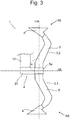
- FIG. 3 shows a further embodiment of a cultivator module 1 according to the present invention in a side view, in which, in contrast to the embodiment of the FIG. 2 a plug connection between the connecting portion 5a of the share units 3.1, 3.2 and the coulter unit 2 is formed.
- the coulter unit 2 has a socket-like receiving section 2b and the common connecting section 5a of the mutually connected share units 3.1, 3.2 is designed like a plug.
- Each of the share units 3.1, 3.2 can be moved by repositioning of the holding position HS in the working position AS.
- the connecting portion 5a is pulled out, for example, in the direction of the connecting axis VA from the receiving portion 2b and inserted in accordance with another, for example, relatively twisted, orientation again.
- the fixation in the respective positions can be done, for example, positive fit, e.g. the cross sections of the connecting portion 5a and the receiving portion 2b deviate from a round shape and can be inserted in the predetermined positions cooperatively into one another.
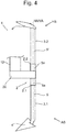
- FIG. 4 An alternative embodiment of a cultivator module 1 according to the present invention shows FIG. 4 , in which also two share units 3.1, 3.2 are provided, which are not connected to each other.
- the connecting portions 5a of the coulter bars 5, 5 ' are plug-shaped and formed by ITAd worne end portions of the coulter bars 5, 5', each extending in the direction of the main axis HA, so that a respective connection axis VA of the connecting portions 5a with the main axis HA of the respective share unit 3.1, 3.2 coincides.
- the coulter support unit 2 comprises a first and second bush-like receiving section 2.1, 2.2 and a fastening section 2c which is suitable for connection to the connecting device 12 of the support frame 11 (see FIG FIG. 5 ) is trained.
- the first and second bush-like receiving portion 2.1, 2.2 are fixed to the mounting portion 2c in such a way that the sleeve-like receiving portions 2.1, 2.2 are opposite with respect to the mounting portion 2c and thus arranged at an angular distance of approximately 180 ° to each other.
- the connecting portion 5a and the female receiving portions 2.1, 2.2 are adapted to form a respective connector.
- the share units 3.1, 3.2 can be moved from the holding position HS to the working position AS by reversing from the first into the second socket-like receiving section 2.1, 2.2, and vice versa.
- the corresponding share units 3.1, 3.2 can exchange their slots in the respective socket-like receiving sections 2.1, 2.2.
- further additional bushing-like receiving sections may be provided and arranged on the attachment section 2c.
- a total of three or a total of four sleeve-like receiving portions may be provided, which may be arranged spaced apart at an angular distance of 120 ° or 90 °.
- particularly advantageous additional positions can be created, which can serve as further holding positions of the share units 3.1, 3.2.
- FIG. 5 shows a rough schematic side view of a tillage device 10 with attached cultivator modules 1 according to a preferred embodiment of the invention.
- the soil cultivation device 10 comprises a support frame 11 on which connection devices 12 are arranged for fastening the cultivator modules 1.
- the connection devices 12 may comprise bent spring steel elements for resilient and detachable attachment of the cultivator modules 1, wherein each cultivator module 1 is connected via the respective share support device 2, each with a connection device 12, preferably by means of a screw connection.
- the tillage device 10 is pulled by a tractor, in particular a tractor in a direction of work AR, such that the tillage takes place in a predetermined processing depth also in the direction of AR.
- the working direction AR essentially corresponds to the direction of a longitudinal axis LA of the soil cultivation device 10.
- Grubberscharmodule 1 attached to the support frame 11 Grubberscharmodule 1 are according to the embodiment according to FIG. 2 executed, with the only difference that both cultivars 4, 4 'of the two share units 3.1, 3.2 are designed equal.
- the share units 3.1, 3.2 can be brought by pivoting or by a rotation about the rotation axis DA of the holding position HS in the working position AS and vice versa, wherein the axis of rotation DA and the longitudinal axis LA of the soil cultivation device 10 are oriented substantially parallel to each other and the respective Main axes HA of the share units 3.1, 3.2 are approximately perpendicular to the axis of rotation DA and to the longitudinal axis LA.
- the soil cultivation device 10 can be done in a particularly simple manner changing the share units 3.1, 3.2 in the corresponding working or holding position AS, HA. Likewise, it proves to be a particular advantage that in the soil tillage device 10 in the context of wear-related maintenance any necessary replacement of cultivars 4, 4 'is facilitated because the share units 3.1, 3.2 are aligned in holding position HS so that the cultivars 4, 4' after above and easier to access. The loosening of screws in the field of cultivator blades 4, 4 'and the restoration of screw connections between cultivar blade 4, 4' and Scharstiel 5, 5 'is simplified and the risk of accidents is reduced.
Landscapes
- Life Sciences & Earth Sciences (AREA)
- Engineering & Computer Science (AREA)
- Mechanical Engineering (AREA)
- Soil Sciences (AREA)
- Environmental Sciences (AREA)
- Soil Working Implements (AREA)
Applications Claiming Priority (1)
| Application Number | Priority Date | Filing Date | Title |
|---|---|---|---|
| DE202017107892.2U DE202017107892U1 (de) | 2017-12-22 | 2017-12-22 | Grubberscharmodul für eine Bodenbearbeitungsvorrichtung |
Publications (2)
| Publication Number | Publication Date |
|---|---|
| EP3501246A1 true EP3501246A1 (fr) | 2019-06-26 |
| EP3501246B1 EP3501246B1 (fr) | 2021-04-28 |
Family
ID=61082637
Family Applications (1)
| Application Number | Title | Priority Date | Filing Date |
|---|---|---|---|
| EP18209570.3A Active EP3501246B1 (fr) | 2017-12-22 | 2018-11-30 | Module de soc d'engin agricole pour un dispositif de traitement du sol |
Country Status (2)
| Country | Link |
|---|---|
| EP (1) | EP3501246B1 (fr) |
| DE (1) | DE202017107892U1 (fr) |
Citations (4)
| Publication number | Priority date | Publication date | Assignee | Title |
|---|---|---|---|---|
| DE646311C (de) * | 1933-06-04 | 1937-06-16 | Ewald Hildebrand & Co | Bodenbearbeitungsgeraet |
| EP0199406A1 (fr) * | 1985-04-11 | 1986-10-29 | C. van der Lely N.V. | Charrue |
| EP2848108A1 (fr) * | 2013-09-04 | 2015-03-18 | Amazonen-Werke H. Dreyer GmbH & Co. KG | Charrue |
| CN206353921U (zh) * | 2016-12-22 | 2017-07-28 | 张秀丽 | 一种农业机械用便于更换的五齿犁头 |
Family Cites Families (2)
| Publication number | Priority date | Publication date | Assignee | Title |
|---|---|---|---|---|
| DE102007005649A1 (de) | 2006-12-07 | 2008-06-12 | Konrad Hendlmeier | Grubberschar mit Zusatzvorrichtung |
| DE202014007134U1 (de) | 2014-09-08 | 2015-12-10 | Konrad Hendlmeier | Bodenbearbeitungsvorrichtung |
-
2017
- 2017-12-22 DE DE202017107892.2U patent/DE202017107892U1/de not_active Expired - Lifetime
-
2018
- 2018-11-30 EP EP18209570.3A patent/EP3501246B1/fr active Active
Patent Citations (4)
| Publication number | Priority date | Publication date | Assignee | Title |
|---|---|---|---|---|
| DE646311C (de) * | 1933-06-04 | 1937-06-16 | Ewald Hildebrand & Co | Bodenbearbeitungsgeraet |
| EP0199406A1 (fr) * | 1985-04-11 | 1986-10-29 | C. van der Lely N.V. | Charrue |
| EP2848108A1 (fr) * | 2013-09-04 | 2015-03-18 | Amazonen-Werke H. Dreyer GmbH & Co. KG | Charrue |
| CN206353921U (zh) * | 2016-12-22 | 2017-07-28 | 张秀丽 | 一种农业机械用便于更换的五齿犁头 |
Also Published As
| Publication number | Publication date |
|---|---|
| EP3501246B1 (fr) | 2021-04-28 |
| DE202017107892U1 (de) | 2018-01-12 |
Similar Documents
| Publication | Publication Date | Title |
|---|---|---|
| EP3226673A1 (fr) | Système de réglage de l'age d'un outil de travail du sol | |
| EP3818793A1 (fr) | Bande coupante et outil combiné doté d'une bande coupante ainsi que machine de traitement du sol agricole | |
| DE29605356U1 (de) | Sägerät, insbesondere für Mulchsaat | |
| EP2281424A1 (fr) | Dispositif de traitement de sol | |
| DE102020133571B4 (de) | Bodenbearbeitungsgerät | |
| EP2965603B1 (fr) | Appareil agricole | |
| EP3501246B1 (fr) | Module de soc d'engin agricole pour un dispositif de traitement du sol | |
| DE102019200171B4 (de) | Bodenbearbeitungsgerät | |
| EP0738459B1 (fr) | Appareil agricole à contrôle de profondeur | |
| DE3546479C2 (fr) | ||
| DE102023103058A1 (de) | Bodenbearbeitungsgerät | |
| EP3235358B1 (fr) | Pointe de bande destinée à être utilisée dans un système de soc pour le traitement du sol | |
| EP2992746B1 (fr) | Dispositif de traitement de sol | |
| DE29514041U1 (de) | Bodenbearbeitungsmaschine | |
| DE102019103043B4 (de) | Landwirtschaftliche Bodenbearbeitungsvorrichtung | |
| EP4014702A1 (fr) | Dispositif de fermenture et de nivellement | |
| DE202017101979U1 (de) | Landwirtschaftliches Bodenbearbeitungsgerät | |
| EP3771317B1 (fr) | Porte-outil pour une machine de travail du sol | |
| DE202021103230U1 (de) | Bodenbearbeitungsgerät | |
| EP0170835A1 (fr) | Charrue | |
| EP3398415A1 (fr) | L'attachement pour tenons | |
| DE10307234B4 (de) | Vorrichtung zur Bodenbearbeitung | |
| DE102016111773B4 (de) | Landwirtschaftliches Bodenbearbeitungsgerät mit Bodenbearbeitungswerkzeugen und Befestigungsanordnung für ein Bodenbearbeitungswerkzeug | |
| DE202023106519U1 (de) | Bodenbearbeitungsgerät | |
| EP3085216A1 (fr) | Machine agricole |
Legal Events
| Date | Code | Title | Description |
|---|---|---|---|
| PUAI | Public reference made under article 153(3) epc to a published international application that has entered the european phase |
Free format text: ORIGINAL CODE: 0009012 |
|
| STAA | Information on the status of an ep patent application or granted ep patent |
Free format text: STATUS: THE APPLICATION HAS BEEN PUBLISHED |
|
| AK | Designated contracting states |
Kind code of ref document: A1 Designated state(s): AL AT BE BG CH CY CZ DE DK EE ES FI FR GB GR HR HU IE IS IT LI LT LU LV MC MK MT NL NO PL PT RO RS SE SI SK SM TR |
|
| AX | Request for extension of the european patent |
Extension state: BA ME |
|
| STAA | Information on the status of an ep patent application or granted ep patent |
Free format text: STATUS: REQUEST FOR EXAMINATION WAS MADE |
|
| 17P | Request for examination filed |
Effective date: 20191205 |
|
| RBV | Designated contracting states (corrected) |
Designated state(s): AL AT BE BG CH CY CZ DE DK EE ES FI FR GB GR HR HU IE IS IT LI LT LU LV MC MK MT NL NO PL PT RO RS SE SI SK SM TR |
|
| GRAP | Despatch of communication of intention to grant a patent |
Free format text: ORIGINAL CODE: EPIDOSNIGR1 |
|
| STAA | Information on the status of an ep patent application or granted ep patent |
Free format text: STATUS: GRANT OF PATENT IS INTENDED |
|
| INTG | Intention to grant announced |
Effective date: 20201028 |
|
| GRAS | Grant fee paid |
Free format text: ORIGINAL CODE: EPIDOSNIGR3 |
|
| GRAA | (expected) grant |
Free format text: ORIGINAL CODE: 0009210 |
|
| STAA | Information on the status of an ep patent application or granted ep patent |
Free format text: STATUS: THE PATENT HAS BEEN GRANTED |
|
| AK | Designated contracting states |
Kind code of ref document: B1 Designated state(s): AL AT BE BG CH CY CZ DE DK EE ES FI FR GB GR HR HU IE IS IT LI LT LU LV MC MK MT NL NO PL PT RO RS SE SI SK SM TR |
|
| REG | Reference to a national code |
Ref country code: GB Ref legal event code: FG4D Free format text: NOT ENGLISH |
|
| REG | Reference to a national code |
Ref country code: CH Ref legal event code: EP |
|
| REG | Reference to a national code |
Ref country code: AT Ref legal event code: REF Ref document number: 1386035 Country of ref document: AT Kind code of ref document: T Effective date: 20210515 |
|
| REG | Reference to a national code |
Ref country code: IE Ref legal event code: FG4D Free format text: LANGUAGE OF EP DOCUMENT: GERMAN |
|
| REG | Reference to a national code |
Ref country code: DE Ref legal event code: R096 Ref document number: 502018004992 Country of ref document: DE |
|
| REG | Reference to a national code |
Ref country code: LT Ref legal event code: MG9D |
|
| PG25 | Lapsed in a contracting state [announced via postgrant information from national office to epo] |
Ref country code: FI Free format text: LAPSE BECAUSE OF FAILURE TO SUBMIT A TRANSLATION OF THE DESCRIPTION OR TO PAY THE FEE WITHIN THE PRESCRIBED TIME-LIMIT Effective date: 20210428 Ref country code: HR Free format text: LAPSE BECAUSE OF FAILURE TO SUBMIT A TRANSLATION OF THE DESCRIPTION OR TO PAY THE FEE WITHIN THE PRESCRIBED TIME-LIMIT Effective date: 20210428 Ref country code: LT Free format text: LAPSE BECAUSE OF FAILURE TO SUBMIT A TRANSLATION OF THE DESCRIPTION OR TO PAY THE FEE WITHIN THE PRESCRIBED TIME-LIMIT Effective date: 20210428 Ref country code: BG Free format text: LAPSE BECAUSE OF FAILURE TO SUBMIT A TRANSLATION OF THE DESCRIPTION OR TO PAY THE FEE WITHIN THE PRESCRIBED TIME-LIMIT Effective date: 20210728 Ref country code: NL Free format text: LAPSE BECAUSE OF FAILURE TO SUBMIT A TRANSLATION OF THE DESCRIPTION OR TO PAY THE FEE WITHIN THE PRESCRIBED TIME-LIMIT Effective date: 20210428 |
|
| PG25 | Lapsed in a contracting state [announced via postgrant information from national office to epo] |
Ref country code: IS Free format text: LAPSE BECAUSE OF FAILURE TO SUBMIT A TRANSLATION OF THE DESCRIPTION OR TO PAY THE FEE WITHIN THE PRESCRIBED TIME-LIMIT Effective date: 20210828 Ref country code: GR Free format text: LAPSE BECAUSE OF FAILURE TO SUBMIT A TRANSLATION OF THE DESCRIPTION OR TO PAY THE FEE WITHIN THE PRESCRIBED TIME-LIMIT Effective date: 20210729 Ref country code: RS Free format text: LAPSE BECAUSE OF FAILURE TO SUBMIT A TRANSLATION OF THE DESCRIPTION OR TO PAY THE FEE WITHIN THE PRESCRIBED TIME-LIMIT Effective date: 20210428 Ref country code: SE Free format text: LAPSE BECAUSE OF FAILURE TO SUBMIT A TRANSLATION OF THE DESCRIPTION OR TO PAY THE FEE WITHIN THE PRESCRIBED TIME-LIMIT Effective date: 20210428 Ref country code: PL Free format text: LAPSE BECAUSE OF FAILURE TO SUBMIT A TRANSLATION OF THE DESCRIPTION OR TO PAY THE FEE WITHIN THE PRESCRIBED TIME-LIMIT Effective date: 20210428 Ref country code: LV Free format text: LAPSE BECAUSE OF FAILURE TO SUBMIT A TRANSLATION OF THE DESCRIPTION OR TO PAY THE FEE WITHIN THE PRESCRIBED TIME-LIMIT Effective date: 20210428 Ref country code: PT Free format text: LAPSE BECAUSE OF FAILURE TO SUBMIT A TRANSLATION OF THE DESCRIPTION OR TO PAY THE FEE WITHIN THE PRESCRIBED TIME-LIMIT Effective date: 20210830 Ref country code: NO Free format text: LAPSE BECAUSE OF FAILURE TO SUBMIT A TRANSLATION OF THE DESCRIPTION OR TO PAY THE FEE WITHIN THE PRESCRIBED TIME-LIMIT Effective date: 20210728 |
|
| REG | Reference to a national code |
Ref country code: NL Ref legal event code: MP Effective date: 20210428 |
|
| PG25 | Lapsed in a contracting state [announced via postgrant information from national office to epo] |
Ref country code: EE Free format text: LAPSE BECAUSE OF FAILURE TO SUBMIT A TRANSLATION OF THE DESCRIPTION OR TO PAY THE FEE WITHIN THE PRESCRIBED TIME-LIMIT Effective date: 20210428 Ref country code: ES Free format text: LAPSE BECAUSE OF FAILURE TO SUBMIT A TRANSLATION OF THE DESCRIPTION OR TO PAY THE FEE WITHIN THE PRESCRIBED TIME-LIMIT Effective date: 20210428 Ref country code: SM Free format text: LAPSE BECAUSE OF FAILURE TO SUBMIT A TRANSLATION OF THE DESCRIPTION OR TO PAY THE FEE WITHIN THE PRESCRIBED TIME-LIMIT Effective date: 20210428 Ref country code: SK Free format text: LAPSE BECAUSE OF FAILURE TO SUBMIT A TRANSLATION OF THE DESCRIPTION OR TO PAY THE FEE WITHIN THE PRESCRIBED TIME-LIMIT Effective date: 20210428 Ref country code: RO Free format text: LAPSE BECAUSE OF FAILURE TO SUBMIT A TRANSLATION OF THE DESCRIPTION OR TO PAY THE FEE WITHIN THE PRESCRIBED TIME-LIMIT Effective date: 20210428 Ref country code: CZ Free format text: LAPSE BECAUSE OF FAILURE TO SUBMIT A TRANSLATION OF THE DESCRIPTION OR TO PAY THE FEE WITHIN THE PRESCRIBED TIME-LIMIT Effective date: 20210428 Ref country code: DK Free format text: LAPSE BECAUSE OF FAILURE TO SUBMIT A TRANSLATION OF THE DESCRIPTION OR TO PAY THE FEE WITHIN THE PRESCRIBED TIME-LIMIT Effective date: 20210428 |
|
| REG | Reference to a national code |
Ref country code: DE Ref legal event code: R097 Ref document number: 502018004992 Country of ref document: DE |
|
| PLBE | No opposition filed within time limit |
Free format text: ORIGINAL CODE: 0009261 |
|
| STAA | Information on the status of an ep patent application or granted ep patent |
Free format text: STATUS: NO OPPOSITION FILED WITHIN TIME LIMIT |
|
| 26N | No opposition filed |
Effective date: 20220131 |
|
| PG25 | Lapsed in a contracting state [announced via postgrant information from national office to epo] |
Ref country code: IS Free format text: LAPSE BECAUSE OF FAILURE TO SUBMIT A TRANSLATION OF THE DESCRIPTION OR TO PAY THE FEE WITHIN THE PRESCRIBED TIME-LIMIT Effective date: 20210828 Ref country code: AL Free format text: LAPSE BECAUSE OF FAILURE TO SUBMIT A TRANSLATION OF THE DESCRIPTION OR TO PAY THE FEE WITHIN THE PRESCRIBED TIME-LIMIT Effective date: 20210428 |
|
| PG25 | Lapsed in a contracting state [announced via postgrant information from national office to epo] |
Ref country code: MC Free format text: LAPSE BECAUSE OF FAILURE TO SUBMIT A TRANSLATION OF THE DESCRIPTION OR TO PAY THE FEE WITHIN THE PRESCRIBED TIME-LIMIT Effective date: 20210428 |
|
| REG | Reference to a national code |
Ref country code: CH Ref legal event code: PL |
|
| PG25 | Lapsed in a contracting state [announced via postgrant information from national office to epo] |
Ref country code: LU Free format text: LAPSE BECAUSE OF NON-PAYMENT OF DUE FEES Effective date: 20211130 Ref country code: IT Free format text: LAPSE BECAUSE OF FAILURE TO SUBMIT A TRANSLATION OF THE DESCRIPTION OR TO PAY THE FEE WITHIN THE PRESCRIBED TIME-LIMIT Effective date: 20210428 Ref country code: BE Free format text: LAPSE BECAUSE OF NON-PAYMENT OF DUE FEES Effective date: 20211130 |
|
| REG | Reference to a national code |
Ref country code: BE Ref legal event code: MM Effective date: 20211130 |
|
| PG25 | Lapsed in a contracting state [announced via postgrant information from national office to epo] |
Ref country code: IE Free format text: LAPSE BECAUSE OF NON-PAYMENT OF DUE FEES Effective date: 20211130 |
|
| PGFP | Annual fee paid to national office [announced via postgrant information from national office to epo] |
Ref country code: FR Payment date: 20221129 Year of fee payment: 5 Ref country code: DE Payment date: 20221130 Year of fee payment: 5 |
|
| PG25 | Lapsed in a contracting state [announced via postgrant information from national office to epo] |
Ref country code: CY Free format text: LAPSE BECAUSE OF FAILURE TO SUBMIT A TRANSLATION OF THE DESCRIPTION OR TO PAY THE FEE WITHIN THE PRESCRIBED TIME-LIMIT Effective date: 20210428 |
|
| GBPC | Gb: european patent ceased through non-payment of renewal fee |
Effective date: 20221130 |
|
| PG25 | Lapsed in a contracting state [announced via postgrant information from national office to epo] |
Ref country code: LI Free format text: LAPSE BECAUSE OF NON-PAYMENT OF DUE FEES Effective date: 20220701 Ref country code: HU Free format text: LAPSE BECAUSE OF FAILURE TO SUBMIT A TRANSLATION OF THE DESCRIPTION OR TO PAY THE FEE WITHIN THE PRESCRIBED TIME-LIMIT; INVALID AB INITIO Effective date: 20181130 Ref country code: CH Free format text: LAPSE BECAUSE OF NON-PAYMENT OF DUE FEES Effective date: 20220701 |
|
| PG25 | Lapsed in a contracting state [announced via postgrant information from national office to epo] |
Ref country code: GB Free format text: LAPSE BECAUSE OF NON-PAYMENT OF DUE FEES Effective date: 20221130 |
|
| PG25 | Lapsed in a contracting state [announced via postgrant information from national office to epo] |
Ref country code: MK Free format text: LAPSE BECAUSE OF FAILURE TO SUBMIT A TRANSLATION OF THE DESCRIPTION OR TO PAY THE FEE WITHIN THE PRESCRIBED TIME-LIMIT Effective date: 20210428 |
|
| REG | Reference to a national code |
Ref country code: DE Ref legal event code: R119 Ref document number: 502018004992 Country of ref document: DE |
|
| PG25 | Lapsed in a contracting state [announced via postgrant information from national office to epo] |
Ref country code: MT Free format text: LAPSE BECAUSE OF FAILURE TO SUBMIT A TRANSLATION OF THE DESCRIPTION OR TO PAY THE FEE WITHIN THE PRESCRIBED TIME-LIMIT Effective date: 20210428 |
|
| PG25 | Lapsed in a contracting state [announced via postgrant information from national office to epo] |
Ref country code: DE Free format text: LAPSE BECAUSE OF NON-PAYMENT OF DUE FEES Effective date: 20240601 |
|
| PG25 | Lapsed in a contracting state [announced via postgrant information from national office to epo] |
Ref country code: FR Free format text: LAPSE BECAUSE OF NON-PAYMENT OF DUE FEES Effective date: 20231130 |
|
| PG25 | Lapsed in a contracting state [announced via postgrant information from national office to epo] |
Ref country code: FR Free format text: LAPSE BECAUSE OF NON-PAYMENT OF DUE FEES Effective date: 20231130 Ref country code: DE Free format text: LAPSE BECAUSE OF NON-PAYMENT OF DUE FEES Effective date: 20240601 |
|
| REG | Reference to a national code |
Ref country code: AT Ref legal event code: MM01 Ref document number: 1386035 Country of ref document: AT Kind code of ref document: T Effective date: 20231130 |
|
| PG25 | Lapsed in a contracting state [announced via postgrant information from national office to epo] |
Ref country code: AT Free format text: LAPSE BECAUSE OF NON-PAYMENT OF DUE FEES Effective date: 20231130 |
|
| PG25 | Lapsed in a contracting state [announced via postgrant information from national office to epo] |
Ref country code: AT Free format text: LAPSE BECAUSE OF NON-PAYMENT OF DUE FEES Effective date: 20231130 |
|
| PG25 | Lapsed in a contracting state [announced via postgrant information from national office to epo] |
Ref country code: TR Free format text: LAPSE BECAUSE OF FAILURE TO SUBMIT A TRANSLATION OF THE DESCRIPTION OR TO PAY THE FEE WITHIN THE PRESCRIBED TIME-LIMIT Effective date: 20210428 |
|
| PGFP | Annual fee paid to national office [announced via postgrant information from national office to epo] |
Ref country code: AT Payment date: 20260410 Year of fee payment: 5 |