EP3501468A1 - Vorspannlenkvorrichtung für einen rollstuhl und rollstuhlgespann mit vorspannlenkvorrichtung - Google Patents
Vorspannlenkvorrichtung für einen rollstuhl und rollstuhlgespann mit vorspannlenkvorrichtung Download PDFInfo
- Publication number
- EP3501468A1 EP3501468A1 EP18202482.8A EP18202482A EP3501468A1 EP 3501468 A1 EP3501468 A1 EP 3501468A1 EP 18202482 A EP18202482 A EP 18202482A EP 3501468 A1 EP3501468 A1 EP 3501468A1
- Authority
- EP
- European Patent Office
- Prior art keywords
- steering
- hollow body
- wheelchair
- head bearing
- steering shaft
- Prior art date
- Legal status (The legal status is an assumption and is not a legal conclusion. Google has not performed a legal analysis and makes no representation as to the accuracy of the status listed.)
- Granted
Links
Images







Classifications
-
- A—HUMAN NECESSITIES
- A61—MEDICAL OR VETERINARY SCIENCE; HYGIENE
- A61G—TRANSPORT, PERSONAL CONVEYANCES, OR ACCOMMODATION SPECIALLY ADAPTED FOR PATIENTS OR DISABLED PERSONS; OPERATING TABLES OR CHAIRS; CHAIRS FOR DENTISTRY; FUNERAL DEVICES
- A61G5/00—Chairs or personal conveyances specially adapted for patients or disabled persons, e.g. wheelchairs
- A61G5/04—Chairs or personal conveyances specially adapted for patients or disabled persons, e.g. wheelchairs motor-driven
- A61G5/047—Chairs or personal conveyances specially adapted for patients or disabled persons, e.g. wheelchairs motor-driven by a modular detachable drive system
Definitions
- the invention relates to a Vorspannlenkvotechnische for a wheelchair and a wheelchair combination with a Vorspannlenkvortechnische.
- Wheelchairs for people with disabilities usually have two large, seen in the forward direction rear drive wheels (rear wheels) and two small, freely pivoting and forward driving direction arranged wheels (front wheels), which are also called castors.
- the rear wheels are usually drivable by hand via a gripping ring in manually driven wheelchairs.
- electrically driven rear wheels can be used.
- both an electric drive motor and a gripping ring for manual drive and additionally comprise a sensor that detects a manually introduced into the gripping drive force, and a control device, the electric drive motor as a function of size and Direction of the manually introduced into the grip ring driving force and an adjustable level of support for delivering a corresponding torque drives.
- the front wheels of the wheelchair designed as freely pivotable castors ensure a high level of maneuverability, which is indispensable especially in so-called indoor operation, ie when the wheelchair is used in closed rooms.
- indoor operation ie when the wheelchair is used in closed rooms.
- the small front wheels are disadvantageous and make even with relatively little bumps operation of the wheelchair impossible.
- small front wheels would dip into depressions from which they could not come out because of their small diameter limited ability to negotiate an obstacle, which then makes driving impossible.
- Vorspannlenkvoriquesen have been developed for wheelchairs in the form of removable additional devices that make it possible to complement the designed for indoor operation wheelchair functionally so and change that it is better suited for outdoor use.
- the assembly of such Vorspannlenkvoriques to a wheelchair is such that the Vorspannlenkvorides is first seen from the front in front of the wheelchair seen in the direction of travel and raised in the course of installation, the freely pivoting front wheels of the wheelchair, so that in the ready state of the assembled wheelchair team this one
- the vehicle is only touching the ground on which it is traveling with the wheel or wheels of the preload steering device and the two large rear wheels of the wheelchair.
- Such a bias steering device for a wheelchair is for example from the EP 3 020 383 A1 known.
- the structure of such a biasing steering device usually provides, based on the bicycle construction before a fork, which serves for the steerable mounting of the wheel of the biasing steering device, hereinafter also called the main gear.
- the so-called fork crown of the fork is rotatably connected to a steerer, hereafter also called steering shaft connected.
- the steering shaft is connected to the frame of the Vorspannlenkvoriques characterized in that it is rotatably supported and held in a control tube. On the outside of such a control tube components are attached, which serve to mount the Vorspannlenkvortechnik on a wheelchair, and other components such as a battery for an electric drive motor.
- Such an arrangement as is known from the EP 3 020 383 A1 has the disadvantage that numerous components such as brake lines, Bowden cables for brakes and / or switching mechanisms and electrical components and components such as batteries, cables and contact points in connection with drive motors, sensors, monitoring and control elements and corresponding contact points are arranged largely unprotected , This not only affects the weather, especially moisture and moisture, but also the risk of mechanical damage due to getting caught on obstacles and a risk of injury to persons due to such snagging.
- a biasing steering device is known from DE 840 575 B known.
- the present invention has for its object to improve a Vorspannlenkvorraum for a wheelchair in view of the above and one with such
- biasing steering device according to the invention and the wheelchair combination according to the invention with such a biasing steering device take account of these aspects with corresponding features in several respects.
- a hollow body for the bearing of the steering shaft that is to say a component which, in addition to an already necessary steering shaft for receiving the steering shaft, has a further or further hollow space, offers an otherwise solid component, as it is known from the bicycle construction head tube, with the same mass a higher strength and stability.
- the hollow body forms, optionally with other, preferably also executed as a hollow body components with which it is firmly connected, for example by welding, a monocoque component, which not only offers high stability and strength at relatively low weight, but also can combine several functions simultaneously ,
- a multi-function monocoque component is a multifunctional monocoque.
- one or more recesses or cavities within the hollow body can be used to receive components.
- These include, for example, one or more accumulators, but also function control transfer elements.
- a function control transmission element is for example a hydraulic or pneumatic control line, an electrical line or an element for the mechanical transmission of forces, for example a Bowden cable.
- the biasing steering device according to the invention may be provided with a drive motor which drives a main or drive wheel of the biasing steering device. This then not only represents a Vorspannlenkvoriques, but is also a traction device for the wheelchair.
- FIGS. show particularly preferred embodiments of the invention.
- the invention is not limited to the embodiments shown.
- the invention includes, as far as is technically feasible, any combination of the technical features that are listed in the claims or described in the description as being relevant to the invention.
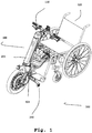
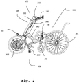
- FIGS. 1 and 2 show an embodiment of a wheelchair combination 500 according to the invention, in which an embodiment of a biasing steering device 100 according to the invention is operatively coupled to a commercial wheelchair 300.
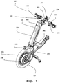
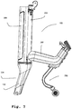
- FIGS. 3 to 18 Details of the embodiment of the biasing steering device 100 according to the invention are in the FIGS. 3 to 18 shown.
- the biasing steering device 100 has a monocoque component 101, that is to say a self-supporting unitary component which has a hollow body main part 201 of a hollow body 200 and a connecting part 280, which is designed as a down tube in the present exemplary embodiment.
- a steering shaft 141 is rotatably mounted in the hollow body 200 and in the hollow body main part 201 of the monocoque component 101.
- the steering shaft 141 is the steerer tube of a fork 104, the fork crown 142, which is rotatably connected to the steerer tube (steering shaft) 141, a main gear 105 leads, which can be driven by an electric motor 106 and braked via a disc brake 107.
- a handlebar 110 is attached at the upper end of the steering shaft 141. Controls for the control of the electric motor 106 and the operation of the disc brake 107 are arranged on the handlebar 110.
- the monocoque component fulfills several functions, it is a multifunctional monocoque.
- the hollow body 200 in the present embodiment by means of the hollow body main part 201, serves to support the steering shaft 141 and to receive functional control transmission elements, while the connecting part 280, optionally in combination with further elements, will be described below. the connection of the biasing steering device 100 to the wheelchair 300 is used.
- the biasing steering apparatus 100 may be connected via a mounting arrangement 130 to a standard wheelchair 300 to the wheelchair combination 500.
- the mounting assembly 130 (see in particular FIG Fig. 5 ) is arranged at the outer end of the connecting part 280 of the monocoque component 101 of the biasing steering device 100 and designed so that it is adjustable and can be connected to a variety of commercial wheelchairs 300.
- Fig. 2 can be seen in ready coupled state of the biasing steering device 100 with the wheelchair 300 small front wheels 302 of the wheelchair, which are usually designed as freely pivotable castors, from the floor on which the wheelchair combination 500 stands lifted so that the wheelchair team 500 as a tricycle the main wheel 105 of the Vorspannlenkvorraum 100 and the two large rear wheels 301 of the wheelchair 300 is.
- the biasing steering apparatus 100 is provided with a stand 290.
- the stand 290 is attached to the connecting portion 280 of the monocoque component 101 of the biasing steering apparatus 100. It will be understood by those skilled in the art that such a stand 290 may be attached to other locations of a biasing steering apparatus.
- the stand 290 is provided with two rolling wheels disposed on a floor contacting portion of the stand.
- the stand allows the preload steering apparatus 100, when decoupled from the wheelchair 300, to be maintained in a mounting position in which the preload steering apparatus 100 rests on the main gear 105 and the two wheels of the stator 290.
- the rolling wheels instead of the rolling wheels, other components may be used to bring the stand 200 into contact with the ground, which components may be both movable components and rigid components.
- the rolling wheels do not touch the ground on which the wheelchair combination 500 stands. They are thus also raised from the ground relative to the mounting position of the biasing steering apparatus 100, as the front wheels 302 of the wheelchair 300 are raised from a position in which the wheelchair, without being coupled to a biasing steering apparatus 100, on its front wheels 302 and its rear wheels 301 stands.
- the stator 290 is connected to the biasing steering device 100 at its upper end of the mounting portion.
- the rolling wheels are attached to the lower end of the Bodenberlickabitess.
- a spring device is arranged between the Bodenberlickabites and the mounting portion.
- the spring means allows the ground contacting portion to pivot elastically with the rolling wheels when coming in contact with an obstacle.
- an elastic pivoting in the direction of travel that is in a direction that in the illustration according to Fig. 2 from left to right and vice versa, possible.
- the spring device can also be arranged at other locations of the stand, including the upper end of the stand, that is, in the illustrated embodiment, the upper end of the mounting portion.
- the in the figures is not shown, could thus be connected, for example, otherwise rigid stator with the interposition of a spring means with a corresponding connection part of a biasing steering device.
- the spring device has two rubber-metal buffers, which are screwed to a first support plate of the Bodenberlickabitess and one of the first support plate opposite second support plate of the mounting portion.
- rubber-metal buffer are, for example, vibration metal buffer of the company Reiff Technical Products GmbH, Reutlingen, Germany, in which an elastomer is arranged between two plates made of galvanized steel.
- These vibration metal buffers have a circular cylindrical shape and have a spring stiffness in the direction of the cylinder axis, which is considerably greater than the spring stiffness in the radial direction.
- two such rubber-metal bumpers are arranged spaced apart in an arrangement direction that is perpendicular to the straight-ahead direction of the wheelchair combination and parallel to the floor.
- the spring device thus has a spring stiffness in the direction of straight travel, which is less than in a direction which is perpendicular to the straight-ahead direction of the wheelchair combination and parallel to the ground, wherein the latter spring stiffness is again lower than that in a direction perpendicular to the ground.
- the monocoque component 101 has the hollow body 200.
- An essential element of the hollow body 200 is the hollow body main part 201 to the hollow body main part 201, the connecting part 280 is attached.
- the hollow body main part 201 may be made of aluminum, for example as an extruded profile.
- the connecting part 280 may also be made
- connection of the connecting part 280 with the hollow body main part 201 can be done by welding.
- the mounting arrangement 130 may have a component 131 which can be inserted into the connecting part 280 designed as a down tube, as well as a latching mechanism 132, which engages in a corresponding latching recess 281 of the connecting part 280 (see FIG Fig. 16 ).
- a head end cover 202 is attached.
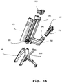
- an accumulator that is, a rechargeable battery 203 are used (see Fig. 16 ).
- the accumulator 203 is designed so that when it is inserted into the hollow body 200, it forms a harmonic surface with it, and has contact points which, when the accumulator 203 is inserted into the recess 205 of the hollow body 200 ready for operation, are in conductive engagement with electrical contacts 206 which are formed in the hollow body 200.
- a seat for an upper steering head bearing 240 and a seat for a lower steering head bearing 250 are arranged on the hollow body 200.
- the arrangement of the upper steering head bearing 240 and the lower steering head bearing 250 on the hollow body 200 according to the invention is an arrangement in which the hollow body is the structural support for the storage of the Steering 141 provides. This can be done in various ways, in particular the fact that the hollow body 200 in cooperation of on the one hand special embodiments of areas of the hollow body 200 and on the other hand other components that serve to hold the upper steering head bearing 240 and the lower steering head bearing 250 on or in the hollow body 200 Guaranteed this stop.
- An illustrated in the figures exemplary embodiment of this storage is explained below, with particular reference to the FIGS. 11 to 14 is referenced.
- An upper headset plate 241 which may be made of aluminum and serves to receive the upper steering head bearing 240, is screwed by means of two screws at an upper end of the hollow body main body 201.
- the handlebar holder 242 thus also functions as a tax rate holding member.
- the lower steering head bearing 250 is held between a lower headset plate 251, for example made of aluminum, which is bolted to a lower end of the hollow body main body 201, and the fork crown 142nd
- Fig. 18 shows a perspective view of the hollow body main body 201
- Fig. 17 shows a plan view of the hollow body main part 201, that is, a view from above, based on the illustration according to Fig. 18
- the hollow body body 201 according to the present embodiment is extruded from aluminum. It will be understood by those skilled in the art that numerous other materials, such as metals, metal alloys, plastics, and / or fiber composites, and other manufacturing and molding techniques may be selected.
- the hollow body 200 has a structural strength which makes it possible to support the steering shaft 141 and thus absorb the forces occurring during operation of the wheelchair combination 500, and, on the other hand, at the same time, owing to its configuration as a hollow body, Receiving space for both the steering shaft 141 and for function control transmission elements, in particular for hydraulic or pneumatic control lines, such as brake lines hydraulic brakes, electrical cables such as cables, and elements for the mechanical transmission of forces, such as Bowden cables for brakes or mechanical switching mechanisms.
- the hollow body main part 201 is of particular importance because, in conjunction with the connecting part 280, it enables a monocoque structure in this respect.
- screw channels 261 are formed, which serve the screw with the upper headset plate 241.
- screw 262 are formed, which serve the screw with the lower headset plate 251.
- Further screw channels 263 at the upper end of the hollow body main part 201 are used for screwing to the head end cover 202.
- the screw can already be created in the extruded profile and the screw can be done by means of thread-forming screws. It is understood that the skilled person also other related alternatives are available, for example, in the extruded profile already provided thread or the use of threaded inserts.
- the hollow body main part 201 is formed so as to have the end-side recess 205 for accommodating the accumulator 203.
- a wall 271 is formed, which defines a steering shaft shaft 270 for receiving the steering shaft 141 together with a corresponding part of the rear outer wall of the hollow body main body 201.
- the wall 271 simultaneously forms the rear wall of the recess 205.
- the wall 271 together with corresponding projections 273 function control transfer shafts 275 for function control transfer elements.
- the grommets 278, which may be made of plastic, for example, serve to carry out the function control transmission elements.
- the grommets 278 have flexible openings through which functional control transfer elements can pass.
- hydraulic brake lines 108 are shown in the figures (see in particular Fig. 3 ).
- a brake lever 109 is attached to each handle of the handlebar rod 110, from each of which a hydraulic brake line 108 leads to a separate brake caliper 107 of the disc brake.
- Another functional control transmission member passed through the interior of the hollow body 200 is an electrical cable 265 which connects a display and control unit 264 to the electric motor 106 and the accumulator 203. This cable runs through another opening, not explicitly shown in the figures, in the head end cover 202.
- the hollow body 200 ensures a high stability with respect to the bearing of the steering shaft and thus the leadership of the main wheel 105 at the same time low mass, compared with a solid component, as it represents, for example, a well-known from the bicycle headset.
Landscapes
- Health & Medical Sciences (AREA)
- Life Sciences & Earth Sciences (AREA)
- Animal Behavior & Ethology (AREA)
- General Health & Medical Sciences (AREA)
- Public Health (AREA)
- Veterinary Medicine (AREA)
- Motorcycle And Bicycle Frame (AREA)
- Steering Devices For Bicycles And Motorcycles (AREA)
Abstract
Description
- Die Erfindung betrifft eine Vorspannlenkvorichtung für einen Rollstuhl und ein Rollstuhlgespann mit einer Vorspannlenkvorrichtung.
- Rollstühle für Menschen mit Behinderung verfügen üblicherweise über zwei große, in Vorwärtsfahrtrichtung gesehen hinten angeordnete Antriebsräder (Hinterräder) und zwei kleine, frei schwenkbare und in Vorwärtsfahrtrichtung vorne angeordnete Laufräder (Vorderräder), die auch Castoren genannt werden. Die Hinterräder sind bei manuell antreibbaren Rollstühlen in der Regel von Hand über einen Greifring antreibbar. Alternativ können auch elektrisch angetriebene Hinterräder verwendet werden. Zudem sind, beispielsweise aus der
DE 198 57 786 A1 , Hinterräder bekannt, die als Hilfsantriebsvorrichtung konzipiert sind, sowohl einen elektrischen Antriebsmotor als auch einen Greifring für manuellen Antrieb aufweisen und zusätzlich einen Sensor, der eine manuell in den Greifring eingeleitete Antriebskraft erfasst, sowie eine Steuereinrichtung, die den elektrischen Antriebsmotor in Abhängigkeit von Größe und Richtung der manuell in den Greifring eingeleiteten Antriebskraft und einem einstellbaren Unterstützungsgrad zur Abgabe eines entsprechenden Drehmoments ansteuert. - Die als frei schwenkbare Castoren ausgeführten Vorderräder des Rollstuhls gewährleisten eine hohe Manövrierfähigkeit, die insbesondere bei sogenanntem Indoor-Betrieb, das heißt bei einer Verwendung des Rollstuhls in geschlossenen Räumen, unabdingbar ist. Bei Outdoor-Betrieb, das heißt bei Betrieb außerhalb geschlossener Räume und insbesondere auf unebenen Wegen, sind die kleinen Vorderräder hingegen nachteilig und machen schon bei relativ geringen Unebenheiten einen Betrieb des Rollstuhls unmöglich. Beispielsweise würden kleine Vorderräder in Vertiefungen eintauchen, aus denen sie wegen ihrer durch den kleinen Durchmesser deutlich eingeschränkten Fähigkeit zum Überwinden eines Hindernisses nicht herauskommen könnten, was dann ein Weiterfahren unmöglich macht.
- Es sind daher für Rollstühle sogenannte Vorspannlenkvorrichtungen entwickelt worden in Form abnehmbarer Zusatzeinrichtungen, die es ermöglichen, den für den Indoor-Betrieb ausgelegten Rollstuhl funktional so zu ergänzen und zu verändern, dass er für den Outdoor-Betrieb besser geeignet ist. Die Montage einer derartigen Vorspannlenkvorrichtung an einen Rollstuhl erfolgt derart, dass die Vorspannlenkvorrichtung zunächst von in Fahrtrichtung gesehen vorne vor dem Rollstuhl platziert wird und im Zuge der Montage die frei schwenkbaren Vorderräder des Rollstuhls angehoben werden, so dass im betriebsfertigen Zustand des derart zusammengefügten Rollstuhlgespanns dieses ein Fahrzeug ist, das den Boden, auf dem es fährt, lediglich berührt mit dem Rad oder den Rädern der Vorspannlenkvorrichtung und den beiden großen Hinterrädern des Rollstuhls. Eine derartige Vorspannlenkvorrichtung für einen Rollstuhl ist beispielsweise aus der
EP 3 020 383 A1 bekannt. - Der Aufbau einer derartigen Vorspannlenkvorrichtung sieht in Anlehnung an den Fahrradbau üblicherweise eine Gabel vor, die zur lenkbaren Lagerung des Rades der Vorspannlenkvorrichtung, im Folgenden auch Hauptrad genannt, dient. Die sogenannte Gabelkrone der Gabel ist drehfest mit einem Gabelschaft, im Folgenden auch Lenkschaft genannt, verbunden. Der Lenkschaft ist mit dem Rahmen der Vorspannlenkvorrichtung dadurch verbunden, dass er in einem Steuerrohr drehbar gelagert und gehalten ist. Außen an einem derartigen Steuerrohr sind Bauelemente befestigt, die der Montage der Vorspannlenkvorrichtung an einem Rollstuhl dienen, sowie weitere Bauteile wie eine Batterie für einen elektrischen Antriebsmotor. Eine derartige Anordnung, wie sie aus der
EP 3 020 383 A1 bekannt ist, weist den Nachteil auf, dass zahlreiche Bauteile wie Bremsleitungen, Bowdenzüge für Bremsen und/oder Schaltmechanismen und elektrische Komponenten und Bauteile wie Batterien, Kabel und Kontaktstellen im Zusammenhang mit Antriebsmotoren, Sensoren, Überwachungs- und Bedienungselementen und entsprechenden Kontaktstellen weitgehend ungeschützt angeordnet sind. Dies betrifft nicht nur Witterungseinflüsse, insbesondere Feuchtigkeit und Nässe, sondern auch die Gefahr mechanischer Beschädigungen durch Hängenbleiben an Hindernissen und einer Verletzungsgefahr von Personen durch derartiges Hängenbleiben. - Eine andere Problematik liegt darin, einerseits die für die Aufnahme der im Betrieb auftretenden Kräfte hinreichende Stabilität der
- Vorspannlenkvorrichtung sicherzustellen und andererseits deren Masse so gering wie möglich zu halten, damit die Handhabung durch die im Rollstuhl sitzende Person möglichst leicht ist.
- Eine Vorspannlenkvorrichtung gemäß dem Oberbegriff des Patentanspruchs 1 ist aus der
DE 840 575 B bekannt. - Der vorliegenden Erfindung liegt die Aufgabe zugrunde, eine Vorspannlenkvorrichtung für einen Rollstuhl im Hinblick auf das vorstehend Dargelegte zu verbessern und ein mit einer derartigen
- Vorspannlenkvorrichtung versehenes Rollstuhlgespann bereitzustellen.
- Die erfindungsgemäße Vorspannlenkvorrichtung und das erfindungsgemäße Rollstuhlgespann mit einer derartigen Vorspannlenkvorrichtung tragen diesen Aspekten mit entsprechenden Merkmalen in mehrerer Hinsicht Rechnung.
- Die Verwendung eines Hohlkörpers für die Lagerung des Lenkschaftes, das heißt eines Bauteils, das neben einem ohnehin notwendigen Lenkschaft-Schacht zur Aufnahme des Lenkschaftes einen weiteren oder weitere Hohlräume aufweist, bietet gegenüber einem ansonsten massiven Bauteil, wie es ein aus dem Fahrradbau bekanntes Steuerrohr darstellt, bei gleicher Masse eine höhere Festigkeit und Stabilität.
- Der Hohlkörper bildet, gegebenenfalls mit weiteren, vorzugsweise ebenfalls als Hohlkörper ausgeführten Bauelementen, mit denen er fest verbunden wird, beispielsweise durch Schweißen, ein Monocoquebauteil, das nicht nur eine hohe Stabilität und Festigkeit bei vergleichsweise geringem Gewicht bietet, sondern auch gleichzeitig mehrere Funktionen verbinden kann. Ein derartiges Monocoquebauteil mit mehreren Funktionen stellt ein Multifunktionsmonocoque dar.
- Insbesondere können ein oder mehrere Ausnehmungen oder Hohlräume innerhalb des Hohlkörpers zur Aufnahme von Bauteilen genutzt werden. Hierzu zählen beispielsweise ein oder mehrere Akkumulatoren, aber auch Funktionssteuerungsübertragungselemente. Ein Funktionssteuerungsübertragungselement ist beispielsweise eine hydraulische oder pneumatische Steuerleitung, eine elektrische Leitung oder ein Element zur mechanischen Übertragung von Kräften, beispielsweise ein Bowdenzug.
- Die erfindungsgemäße Vorspannlenkvorrichtung kann mit einem Antriebsmotor versehen sein, der ein Haupt- bzw. Antriebsrad der Vorspannlenkvorrichtung antreibt. Diese stellt dann nicht nur eine Vorspannlenkvorrichtung dar, sondern ist gleichzeitig ein Zugmittel für den Rollstuhl.
- Die Erfindung sowie das technische Umfeld werden nachfolgend anhand der Figuren näher erläutert. Es ist darauf hinzuweisen, dass die Figuren besonders bevorzugte Ausführungsvarianten der Erfindung zeigen. Die Erfindung ist jedoch nicht auf die gezeigten Ausführungsvarianten beschränkt. Insbesondere umfasst die Erfindung, soweit es technisch sinnvoll ist, beliebige Kombinationen der technischen Merkmale, die in den Ansprüchen aufgeführt oder in der Beschreibung als erfindungsrelevant beschrieben sind.
- Es zeigen:
- Fig. 1
- eine perspektivische Ansicht einer Ausführungsform eines Rollstuhlgespanns,
- Fig. 2
- eine Seitenansicht des Rollstuhlgespanns gemäß
Fig. 1 , - Fig. 3
- eine erste perspektivische Ansicht einer Ausführungsform einer Vorspannlenkvorrichtung,
- Fig. 4
- eine Seitenansicht der Vorspannlenkvorrichtung gemäß
Fig. 3 , - Fig. 5
- eine zweite perspektivische Ansicht der Vorspannlenkvorrichtung gemäß
Fig. 3 , - Fig. 6
- eine Seitenansicht einer Ausführungsform eines Multifunktionsmonocoques mit Ständer,
- Fig. 7
- eine Seitenansicht des Multifunktionsmonocoques gemäß
Fig. 6 mit weggelassener Kopfende-Abdeckkappe, - Fig. 8
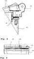
- eine Detailansicht einer oberen Lagerstelle eines Lenkkopflagers,
- Fig. 9
- eine Detailansicht einer unteren Lagerstelle eines Lenkkopflagers,
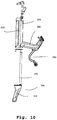
- Fig. 10
- eine Explosionsansicht des Multifunktionsmonocoques gemäß
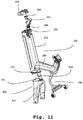
Fig. 6 in Seitenansicht, - Fig. 11
- eine Explosionsansicht des Multifunktionsmonocoques gemäß
Fig. 6 in einer ersten perspektivischen Ansicht, - Fig. 12
- eine Explosionsansicht des Multifunktionsmonocoques gemäß
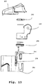
Fig. 6 in einer zweiten perspektivischen Ansicht, - Fig. 13
- eine Explosionsansicht der oberen Lagerstelle gemäß
Fig. 8 , - Fig. 14
- eine Explosionsansicht der unteren Lagerstelle gemäß
Fig. 9 , - Fig. 15
- eine Explosionsansicht des Multifunktionsmonocoques gemäß
Fig. 6 in einer dritten perspektivischen Ansicht, - Fig. 16
- eine Explosionsansicht des Multifunktionsmonocoques gemäß
Fig. 6 in einer vierten perspektivischen Ansicht, - Fig. 17
- eine Draufsicht auf ein Hohlkörperhauptteil und
- Fig. 18
- eine perspektivische Ansicht eines Hohlkörperhauptteils.
- Die Figuren sind im Maßstab nicht einheitlich, damit anhand von Vergrößerungen Einzelheiten deutlicher dargestellt werden können. Zudem sind zum Zwecke der Übersichtlichkeit nicht in allen Darstellungen alle Bezugszeichen eingezeichnet, um die Darstellungen nicht zu überladen. Jedes Bezugszeichen ist jedoch zumindest auf einer Figur eingetragen und die gedankliche Übertragung auf andere Figuren stellt den Fachmann vor keine Probleme.
- Die
Figuren 1 und2 zeigen ein Ausführungsbeispiel eines erfindungsgemäßen Rollstuhlgespanns 500, bei dem eine Ausführungsform einer erfindungsgemäßen Vorspannlenkvorrichtung 100 betriebsfertig an einen handelsüblichen Rollstuhl 300 angekoppelt ist. - Einzelheiten der Ausführungsform der erfindungsgemäßen Vorspannlenkvorrichtung 100 sind in den
Figuren 3 bis 18 dargestellt. - Die Vorspannlenkvorrichtung 100 weist ein Monocoquebauteil 101 auf, das heißt ein selbsttragendes einheitliches Bauteil, das ein Hohlkörperhauptteil 201 eines Hohlkörpers 200 sowie ein, im vorliegenden Ausführungsbeispiel als Unterrohr ausgeführtes, Verbindungsteil 280 aufweist. In dem Hohlkörper 200 bzw. in dem Hohlkörperhauptteil 201 des Monocoquebauteils 101 ist ein Lenkschaft 141 drehbar gelagert. Der Lenkschaft 141 ist der Gabelschaft einer Gabel 104, deren Gabelkrone 142, die mit dem Gabelschaft (Lenkschaft) 141 drehfest verbunden ist, ein Hauptrad 105 führt, das durch einen Elektromotor 106 angetrieben und über eine Scheibenbremse 107 gebremst werden kann. An dem oberen Ende des Lenkschafts 141 ist eine Lenkerstange 110 befestigt ist. Bedienungselemente für die Ansteuerung des Elektromotors 106 und die Betätigung der Scheibenbremse 107 sind an der Lenkerstange 110 angeordnet.
- Da das Monocoquebauteil mehrere Funktionen erfüllt, ist es ein Multifunktionsmonocoque.
- Wie nachfolgend noch eingehend erläutert wird, dient der Hohlkörper 200, in der vorliegenden Ausführungsform mittels des Hohlkörperhauptteils 201, der Lagerung des Lenkschaftes 141 und der Aufnahme von Funktionssteuerungsübertragungselementen, während das Verbindungsteil 280, gegebenenfalls in Verbindung mit weiteren Elementen, wie nachfolgend noch beschrieben wird, der Anbindung der Vorspannlenkvorrichtung 100 an den Rollstuhl 300 dient.
- Die Vorspannlenkvorrichtung 100 kann über eine Montageanordnung 130 mit einem handelsüblichen Rollstuhl 300 verbunden werden zu dem Rollstuhlgespann 500. Die Montageanordnung 130 (siehe insbesondere
Fig. 5 ) ist an dem äußeren Ende des Verbindungsteils 280 des Monocoquebauteils 101 der Vorspannlenkvorrichtung 100 angeordnet und so ausgelegt, dass sie einstellbar ist und mit einer Vielzahl handelsüblicher Rollstühle 300 verbunden werden kann. - Wie insbesondere aus
Fig. 2 ersichtlich, sind in betriebsfertig angekoppeltem Zustand der Vorspannlenkvorrichtung 100 mit dem Rollstuhl 300 kleine Vorderräder 302 des Rollstuhls, die üblicherweise als frei schwenkbare Castoren ausgeführt sind, von dem Boden, auf dem das Rollstuhlgespann 500 steht, abgehoben, so dass das Rollstuhlgespann 500 als Dreirad auf dem Hauptrad 105 der Vorspannlenkvorrichtung 100 und den beiden großen Hinterrädern 301 des Rollstuhls 300 steht. - Die Vorspannlenkvorrichtung 100 ist mit einem Ständer 290 versehen. In der dargestellten Ausführungsform ist der Ständer 290 an dem Verbindungsteil 280 des Monocoquebauteils 101 der Vorspannlenkvorrichtung 100 befestigt. Es versteht sich für den Fachmann, dass ein derartiger Ständer 290 auch an anderen Positionen einer Vorspannlenkvorrichtung befestigt werden kann.
- Der Ständer 290 ist mit zwei Rollrädern versehen, die an einem Bodenberührabschnitt des Ständers angeordnet sind. Der Ständer ermöglicht es, die Vorspannlenkvorrichtung 100 dann, wenn sie von dem Rollstuhl 300 entkoppelt ist, in einer Montagestellung zu halten, in der die Vorspannlenkvorrichtung 100 auf dem Hauptrad 105 und den beiden Rollrädern des Ständers 290 steht. Es versteht sich, dass statt der Rollräder auch andere Bauteile verwendet werden können, um den Ständer 200 mit dem Boden in Berührung zu bringen, wobei diese Bauteile sowohl bewegliche Bauteile als auch starre Bauteile sein können.
- In der Betriebsstellung der Vorspannlenkvorrichtung 100, das heißt in der Stellung, in der die Vorspannlenkvorrichtung 100 mit dem Rollstuhl 300 zu einem Rollstuhlgespann 500 verbunden ist, wie sie in
Fig. 2 dargestellt ist, berühren die Rollräder nicht den Boden, auf dem das Rollstuhlgespann 500 steht. Sie sind somit gegenüber der Montagestellung der Vorspannlenkvorrichtung 100 ebenso vom Boden abgehoben, wie die Vorderräder 302 des Rollstuhls 300 gegenüber einer Stellung vom Boden abgehoben sind, in der der Rollstuhl, ohne mit einer Vorspannlenkvorrichtung 100 verkoppelt zu sein, auf seinen Vorderrädern 302 und seinen Hinterrädern 301 steht. - Der Ständer 290 ist mit seinem oberen Ende des Montageabschnitts mit der Vorspannlenkvorrichtung 100 verbunden. Wie bereits ausgeführt, sind die Rollräder am unteren Ende des Bodenberührabschnitts befestigt. Zwischen dem Bodenberührabschnitt und dem Montageabschnitt ist eine Federeinrichtung angeordnet. Die Federeinrichtung ermöglicht es, dass der Bodenberührabschnitt mit den Rollrädern elastisch verschwenken kann, wenn er mit einem Hindernis in Berührung kommt. Insbesondere ist ein elastisches Verschwenken in Fahrtrichtung, das heißt in einer Richtung, die bei der Darstellung gemäß
Fig. 2 von links nach rechts und umgekehrt verläuft, möglich. - Es versteht sich, dass die Federeinrichtung auch an anderen Stellen des Ständers angeordnet sein kann, einschließlich dem oberen Ende des Ständers, das heißt bei der dargestellten Ausführungsform dem oberen Ende des Montageabschnitts. Bei einer derartigen Ausführungsform, die in den Figuren nicht gezeigt ist, könnte somit ein beispielsweise im Übrigen starrer Ständer unter Zwischenschaltung einer Federeinrichtung mit einem entsprechenden Verbindungsteil einer Vorspannlenkvorrichtung verbunden sein.
- Die Federeinrichtung weist zwei Gummi-Metall-Puffer auf, die mit einer ersten Trägerplatte des Bodenberührabschnitts und einer der ersten Trägerplatte gegenüberliegenden zweiten Trägerplatte des Montageabschnitts verschraubt sind. Gut geeignet als derartige Gummi-Metall-Puffer sind beispielsweise Schwingmetallpuffer der Firma Reiff Technische Produkte GmbH, Reutlingen, Deutschland, bei denen ein Elastomer zwischen zwei Platten aus verzinktem Stahl angeordnet ist. Diese Schwingmetallpuffer weisen eine kreiszylindrische Form auf und haben eine Federsteifigkeit in Richtung der Zylinderachse, die erheblich größer ist als die Federsteifigkeit in radialer Richtung. Bei der in den Figuren gezeigten Ausführungsformen des Ständers 290 sind zwei derartige Gummi-Metall-Puffer zueinander beabstandet in einer Anordnungsrichtung angeordnet, die senkrecht zur Geradeausfahrrichtung des Rollstuhlgespanns und parallel zum Boden verläuft. Die Federeinrichtung weist somit eine Federsteifigkeit in Geradeausfahrrichtung auf, die geringer ist als in einer Richtung, welche senkrecht zur Geradeausfahrrichtung des Rollstuhlgespanns und parallel zum Boden verläuft, wobei die letztgenannte Federsteifigkeit nochmals geringer ist als diejenige in einer Richtung senkrecht zum Boden.
- Nachfolgend werden der Aufbau des Monocoquebauteils 101, des Hohlkörpers 200 und des Hohlkörperhauptteils 201 und deren Zusammenwirken mit entsprechenden Komponenten der Vorspannlenkvorrichtung 100 beschrieben.
- Das Monocoquebauteil 101 weist den Hohlkörper 200 auf. Ein wesentliches Element des Hohlkörpers 200 ist der Hohlkörperhauptteil 201 An dem Hohlkörperhauptteil 201 ist das Verbindungsteil 280 befestigt. Das Hohlkörperhauptteil 201 kann aus Aluminium gefertigt sein, beispielsweise als Strangpressprofil. Das Verbindungsteil 280 kann ebenfalls aus
- Aluminium gefertigt sein, beispielsweise mittels eines Hydroformingverfahrens. Die Verbindung des Verbindungsteils 280 mit dem Hohlkörperhauptteil 201 kann durch Schweißen erfolgen. Die Montageanordnung 130 kann ein Bauelement 131 aufweisen, das in das als Unterrohr ausgeführte Verbindungsteil 280 einführbar ist, sowie einen Rastmechanismus 132, der in eine entsprechende Rast-Ausnehmung 281 des Verbindungsteils 280 eingreift (siehe
Fig. 16 ). - An dem, bezogen auf die beispielsweise in
Fig. 2 dargestellte Betriebsposition, oberen Ende des Hohlkörpers 200 ist eine Kopfende-Abdeckung 202 angebracht. In eine, bezogen auf die beispielsweise inFig. 2 dargestellte Betriebsposition, stirnseitige Ausnehmung 205 des Hohlkörpers 200 kann ein Akkumulator, das heißt eine wiederaufladbare Batterie 203 eingesetzt werden (sieheFig. 16 ). Der Akkumulator 203 ist so ausgeführt, dass er dann, wenn er in den Hohlkörper 200 eingesetzt ist, mit diesem eine harmonische Oberfläche bildet, und weist Kontaktstellen auf, die dann, wenn der Akkumulator 203 betriebsfertig in die Ausnehmung 205 des Hohlkörpers 200 eingesetzt ist, in leitendem Eingriff sind mit elektrischen Kontakten 206, die in dem Hohlkörper 200 ausgebildet sind. - An dem Hohlkörper 200 sind ein Sitz für ein oberes Lenkkopflager 240 und ein Sitz für ein unteres Lenkkopflager 250 angeordnet. Das obere Lenkkopflager 240 und das untere Lenkkopflager 250 dienen der Lagerung des Lenkschafts 141. Eine Anordnung des oberen Lenkkopflagers 240 und des unteren Lenkkopflagers 250 an dem Hohlkörper 200 im Sinne der Erfindung ist eine Anordnung, in denen der Hohlkörper den strukturellen Halt für die Lagerung des Lenkschafts 141 bereitstellt. Dies kann auf verschiedene Weisen erfolgen, insbesondere dadurch, dass der Hohlkörper 200 im Zusammenwirken von einerseits speziellen Ausgestaltungen von Bereichen des Hohlkörpers 200 und andererseits weiteren Bauteilen, die dem Halten des oberen Lenkkopflagers 240 und des unteren Lenkkopflagers 250 an bzw. in dem Hohlkörper 200 dienen, diesen Halt gewährleistet. Eine in den Figuren dargestellte beispielhafte Ausführungsform dieser Lagerung wird nachfolgend erläutert, wobei insbesondere auf die
Figuren 11 bis 14 verwiesen wird. - Eine obere Steuersatzträgerplatte 241, die aus Aluminium gefertigt sein kann und der Aufnahme des oberen Lenkkopflagers 240 dient, ist mittels zweier Schrauben an einem oberen Ende des Hohlkörperhauptteils 201 verschraubt. Ein Lenkerstangenhalter 242, an dem die Lenkerstange 110 befestigt werden und der ebenfalls aus Aluminium gefertigt sein kann, ist auf den Lenkschaft 141 aufgeklemmt. Der Lenkerstangenhalter 242 fungiert somit auch als Steuersatzhalteelement.
- Eine beispielsweise aus Stahl gefertigte Lenkkopflagermutter 243 ist auf ein hierzu an dem Lenkschaft 141 ausgebildetes Gewinde geschraubt und ermöglicht ein Halten der Anordnung und Einstellen des Spiels des Lenkkopflagers.
- Das untere Lenkkopflager 250 wird gehalten zwischen einer unteren Steuersatzträgerplatte 251, beispielsweise gefertigt aus Aluminium, die mit einem unteren Ende des Hohlkörperhauptteils 201 verschraubt ist, und der Gabelkrone 142.
- Nachfolgend wird die Ausgestaltung der Hohlkörperhauptteils 201 näher erläutert, wobei insbesondere auf die
Figuren 17 und18 verwiesen wird.Fig. 18 zeigt eine perspektivische Ansicht des Hohlkörperhauptteils 201 undFig. 17 zeigt eine Draufsicht auf das Hohlkörperhauptteil 201, das heißt eine Ansicht von oben, bezogen auf die Darstellung gemäßFig. 18 . Das Hohlkörperhauptteil 201 gemäß der vorliegenden Ausführungsform ist im Strangpressverfahren aus Aluminium hergestellt. Es versteht sich für den Fachmann, dass zahlreiche andere Materialien, beispielsweise Metalle, Metalllegierungen, Kunststoffe, und/oder Faserverbundwerkstoffe, und andere Herstellungs- und Formungsverfahren gewählt werden können. Der Hohlkörper 200 weist einerseits eine Strukturfestigkeit auf, die die Lagerung des Lenkschafts 141 ermöglicht und damit die im Betrieb des Rollstuhlgespanns 500 auftretenden Kräfte aufnehmen kann, und bietet andererseits gleichzeitig, durch seine Ausgestaltung als Hohlkörper, Aufnahmeraum für sowohl den Lenkschaft 141 als auch für Funktionssteuerungsübertragungselemente, insbesondere für hydraulische oder pneumatische Steuerleitungen, beispielsweise Bremsleitungen hydraulischer Bremsen, elektrische Leitungen wie beispielsweise Kabel, und Elemente zur mechanischen Übertragung von Kräften, beispielsweise Bowdenzüge für Bremsen oder mechanische Schaltmechanismen. Dem Hohlkörperhauptteil 201 gemäß der vorliegenden Ausführungsform kommt dabei besondere Bedeutung bei, da es, in Verbindung mit dem Verbindungsteil 280, eine diesbezügliche Monocoquestruktur ermöglicht. - Am oberen Ende des Hohlkörperhauptteils 201 sind Schraubkanäle 261 ausgebildet, die der Verschraubung mit der oberen Steuersatzträgerplatte 241 dienen. Am unteren Ende des Hohlkörperhauptteils 201 sind Schraubkanäle 262 ausgebildet, die der Verschraubung mit der unteren Steuersatzträgerplatte 251 dienen. Weitere Schraubkanäle 263 am oberen Ende des Hohlkörperhauptteils 201 dienen der Verschraubung mit der Kopfende-Abdeckung 202. Die Schraubkanäle können bereits im Strangpressprofil angelegt sein und die Verschraubung kann mittels gewindefurchender Schrauben erfolgen. Es versteht sich, dass dem Fachmann zudem weitere diesbezügliche Alternativen zur Verfügung stehen, beispielsweise in dem Strangpressprofil bereits vorgesehene Gewinde oder die Verwendung von Gewindeeinsätzen.
- Das Hohlkörperhauptteil 201 gemäß der vorliegenden Ausführungsform ist so ausgebildet, dass es die stirnseitige Ausnehmung 205 zur Aufnahme des Akkumulators 203 aufweist. In dem Hohlkörperhauptteil 201 ist eine Wand 271 ausgebildet, die zusammen mit einem entsprechenden Teil der rückwärtigen Außenwand des Hohlkörperhauptteils 201 einen Lenkschaft-Schacht 270 zur Aufnahme des Lenkschafts 141 definiert. Die Wand 271 bildet gleichzeitig die Rückwand der Ausnehmung 205. Zudem bildet die Wand 271 zusammen mit entsprechenden Vorsprüngen 273 Funktionssteuerungsübertragungselemente-Schächte 275 für Funktionssteuerungsübertragungselemente.
- Am oberen und unteren Ende des Hohlkörperhauptteils 201 sind Tüllen-Ausnehmungen 277 zur Aufnahme von Tüllen 278 (siehe insbesondere
Figuren 13 und14 ) vorgesehen. Die Tüllen 278, die beispielsweise aus Kunststoff gefertigt sein können, dienen der Durchführung der Funktionssteuerungsübertragungselemente. - Die Tüllen 278 weisen flexible Öffnungen auf, durch die Funktionssteuerungsübertragungselemente hindurch geführt werden können. Als Beispiel für Funktionssteuerungsübertragungselemente sind in den Figuren hydraulische Bremsleitungen 108 dargestellt (siehe insbesondere
Fig. 3 ). Bei der dargestellten Ausführungsform ist an jedem Handgriff der Lenkerstange 110 jeweils ein Bremshebel 109 angebracht, von dem aus jeweils eine hydraulische Bremsleitung 108 zu einem jeweils separaten Bremssattel der Scheibenbremse 107 führt. Dies ergibt eine zusätzliche Sicherheit dadurch, dass, obwohl nur eine Scheibenbremse gegeben ist, mit jeder Hand gebremst werden kann. Ein weiteres Funktionssteuerungsübertragungselement, das durch das Innere des Hohlkörpers 200 hindurch geführt ist, ist ein elektrisches Kabel 265, das ein Anzeige- und Steuergerät 264 mit dem Elektromotor 106 und dem Akkumulator 203 verbindet. Dieses Kabel verläuft durch eine weitere, in den Figuren nicht explizit dargestellte Öffnung in der Kopfende-Abdeckung 202. Es versteht sich, dass weitere Funktionssteuerungsübertragungselemente, die aus Gründen der Übersichtlichkeit in den Figuren nicht dargestellt sind, vorgesehen und in den Hohlkörper hinein bzw. durch diesen hindurch verlegt sein können. Hierzu zählt beispielsweise eine elektrische Leitung, die von einem nach Art eines Gasgriffes bei Motorrädern ausgebildeten Steuerungselement am Ende der Lenkerstange 110 weg führt oder ein Kabel, das von einer USB-Buchse, die beispielsweise auf der Kopfende-Abdeckung 202 angeordnet sein kann, weg führt. - Die Tüllen 278 und weitere entsprechende, nicht dargestellte Öffnungen sowie die Ausgestaltung des Hohlkörpers 200 mit den am Hohlkörperhauptkörper 201 ausgebildeten Funktionssteuerungsübertragungselemente-Schächten 275 ermöglichen es, dass diese Funktionssteuerungsübertragungselemente sicher verlegt werden können und deren Beschädigung und Verschmutzen sowie ein Verheddern oder Verfangen darin vermieden wird.
- Gleichzeitig gewährleistet der Hohlkörper 200 eine hohe Stabilität bezüglich der Lagerung des Lenkschaftes und damit der Führung des Hauptrades 105 bei gleichzeitig geringer Masse, verglichen mit einem massiven Bauteil, wie es beispielsweise ein aus dem Fahrradbau bekanntes Steuerrohr darstellt.
-
- 100
- Vorspannlenkvorrichtung
- 101
- Monocoquebauteil
- 104
- Gabel
- 105
- Hauptrad
- 106
- Elektromotor
- 107
- Scheibenbremse
- 108
- Bremsleitung
- 109
- Bremshebel
- 110
- Lenkerstange
- 130
- Montageanordnung
- 131
- Bauelement
- 132
- Rastmechanismus
- 141
- Lenkschaft
- 142
- Gabelkrone
- 200
- Hohlkörper
- 201
- Hohlkörperhaupteil
- 202
- Kopfende-Abdeckung
- 203
- Akkumulator (wiederaufladbare Batterie)
- 205
- Ausnehmung
- 206
- elektrischer Kontakt
- 240
- oberes Lenkkopflager
- 241
- obere Steuersatzträgerplatte
- 242
- Steuersatzhalteelement/Lenkerstangenhalter
- 243
- Lenkkopflagermutter
- 250
- unteres Lenkkopflager
- 251
- untere Steuersatzträgerplatte
- 261
- Schraubkanal
- 262
- Schraubkanal
- 263
- Schraubkanal
- 264
- Anzeige- und Steuergerät
- 265
- elektrisches Kabel
- 270
- Lenkschaft-Schacht
- 271
- Wand
- 273
- Vorsprung
- 275
- Funktionssteuerungsübertragungselemente-Schacht
- 277
- Tüllen-Ausnehmung
- 278
- Tülle
- 280
- Verbindungsteil
- 281
- Rastausnehmung
- 290
- Ständer
- 300
- Rollstuhl
- 301
- Hinterräder
- 302
- Vorderräder
- 500
- Rollstuhlgespann
Claims (10)
- Vorspannlenkvorrichtung (100) für einen Rollstuhl (300), wobei die Vorspannlenkvorrichtung (100) mindestens ein Rad (105) aufweist, das über einen Lenkschaft (141) lenkbar ist,
mit einem Hohlkörper (200), wobei der Hohlkörper (200) aufweist:einen Sitz für ein oberes Lenkkopflager (240) zur Lagerung des Lenkschaftes (141),einen Sitz für ein unteres Lenkkopflager (250) zur Lagerung des Lenkschaftes (141),einen Lenkschaft-Schacht (270) für die Aufnahme des Lenkschaftes (141),mindestens eine Einführungsstelle (277) für mindestens ein Funktionssteuerungsübertragungselement (108, 265) undmindestens eine Ausführungsstelle (277) für mindestens ein Funktionssteuerungsübertragungselement (108, 265),wobei ein Funktionssteuerungsübertragungselement (108, 265) ein Element ist aus einer Gruppe von Elementen, aufweisend eine hydraulische oderpneumatische Steuerleitung (108), eine elektrische Leitung (265) oder ein Element zur mechanischen Übertragung von Kräften,gekennzeichnet durchein Monocoquebauteil (101), das den Hohlkörper (200) sowie ein Verbindungsteil (280) aufweist, das der Anbindung der Vorspannlenkvorrichtung (100) an dem Rollstuhl (300) dient. - Vorspannlenkvorrichtung (100) nach Anspruch 1, dadurch gekennzeichnet, dass der Sitz für das oberes Lenkkopflager (240) eine obere Steuersatzträgerplatte (241) und ein Steuersatzhalteelement (242) aufweist, wobei das obere Lenkkopflager (240) zwischen der oberen Steuersatzträgerplatte (241) und dem Steuersatzhalteelement (242) gehalten wird.
- Vorspannlenkvorrichtung (100) nach Anspruch 2, dadurch gekennzeichnet, dass der Lenkschaft (141) ein Gewinde aufweist und das Lenkkopflagerspiel mittels einer auf das Gewindes des Lenkschaftes (141) aufgeschraubten Lenkkopflagermutter (243) über das Steuersatzhalteelement (242) einstellbar ist.
- Vorspannlenkvorrichtung (100) nach einem der vorstehenden Ansprüche 2 oder 3, dadurch gekennzeichnet, dass das Steuersatzhalteelement (242) als Lenkerstangenhalter (242) ausgebildet ist.
- Vorspannlenkvorrichtung (100) nach einem der vorstehenden Ansprüche, dadurch gekennzeichnet, dass der Sitz für das untere Lenkkopflager (250) eine untere Steuersatzträgerplatte (251) aufweist, wobei das untere Lenkkopflager (250) zwischen der unteren Steuersatzträgerplatte (251) und einer Gabelkrone (142) gehalten wird.
- Vorspannlenkvorrichtung (100) nach einem der vorstehenden Ansprüche, dadurch gekennzeichnet, dass der Hohlkörper (200) ein Hohlkörperhauptteil (201) aufweist mit einer Ausnehmung (205) zur Aufnahme eines Akkumulators (203).
- Vorspannlenkvorrichtung (100) nach einem der vorstehenden Ansprüche, dadurch gekennzeichnet, dass der Hohlkörper (200) ein Hohlkörperhauptteil (201) aufweist, das im Strangpressverfahren als einheitliches Bauteil hergestellt ist.
- Vorspannlenkvorrichtung (100) nach einem der vorstehenden Ansprüche 1 bis 7, dadurch gekennzeichnet, dass das Verbindungsteil (280) mit dem Hohlkörperhauptteil (201) verschweißt ist.
- Vorspannlenkvorrichtung (100) nach Anspruch 8, dadurch gekennzeichnet, dass das Verbindungsteil (280) und das Hohlkörperhauptteil (201) aus Aluminium gefertigt sind, das Verbindungsteil (280) vorzugsweise durch ein Hydroformingverfahren.
- Rollstuhlgespann (500) mit einer Vorspannlenkvorrichtung (100) für einen Rollstuhl (300) gemäß einem der vorstehenden Ansprüche 1 bis 9.
Applications Claiming Priority (1)
| Application Number | Priority Date | Filing Date | Title |
|---|---|---|---|
| DE102017130681.1A DE102017130681B3 (de) | 2017-12-20 | 2017-12-20 | Vorspannlenkvorrichtung für einen Rollstuhl und Rollstuhlgespann mit Vorspannlenkvorrichtung |
Publications (2)
| Publication Number | Publication Date |
|---|---|
| EP3501468A1 true EP3501468A1 (de) | 2019-06-26 |
| EP3501468B1 EP3501468B1 (de) | 2021-09-01 |
Family
ID=63998541
Family Applications (1)
| Application Number | Title | Priority Date | Filing Date |
|---|---|---|---|
| EP18202482.8A Active EP3501468B1 (de) | 2017-12-20 | 2018-10-25 | Vorspannlenkvorrichtung für einen rollstuhl und rollstuhlgespann mit vorspannlenkvorrichtung |
Country Status (2)
| Country | Link |
|---|---|
| EP (1) | EP3501468B1 (de) |
| DE (1) | DE102017130681B3 (de) |
Cited By (2)
| Publication number | Priority date | Publication date | Assignee | Title |
|---|---|---|---|---|
| KR20240000387U (ko) * | 2022-08-22 | 2024-02-29 | 주식회사 프론테크 | 휠체어의 보조 동력원을 제공하기 위한 전동보조장치 |
| KR20240026633A (ko) * | 2022-08-22 | 2024-02-29 | 주식회사 프론테크 | 휠체어의 보조 동력원을 제공하기 위한 전동보조장치 |
Families Citing this family (3)
| Publication number | Priority date | Publication date | Assignee | Title |
|---|---|---|---|---|
| KR102940900B1 (ko) * | 2020-09-28 | 2026-03-18 | 현대자동차주식회사 | 퍼스널 모빌리티의 견인모듈 및 이를 포함하는 퍼스널 모빌리티, 퍼스널 모빌리티의 제어방법 |
| US12502320B2 (en) | 2021-12-20 | 2025-12-23 | Permobil, Inc. | System to adjust drive operation and performance in response to detection of a front add-on for a wheelchair |
| US12533272B2 (en) | 2021-12-20 | 2026-01-27 | Permobil, Inc. | Self-aligning collapsible front add-on for a wheelchair |
Citations (4)
| Publication number | Priority date | Publication date | Assignee | Title |
|---|---|---|---|---|
| US3387681A (en) * | 1966-02-14 | 1968-06-11 | Rodney R. Rabjohn | Power operated wheel chair |
| US5651422A (en) * | 1994-04-22 | 1997-07-29 | The Center For Innovative Technology | Universal-fit, quick-connect power drive/steer attachment for wheelchair |
| WO2004105672A1 (en) * | 2003-05-30 | 2004-12-09 | Izumi, D.O.O. | Supplementary driving mechanism of the muscle-driven vehicle for accelerated rehabilitation of a paralyzed arm |
| US20060000664A1 (en) * | 2004-07-02 | 2006-01-05 | Chao-Kuo Huang | Motorized apparatus for towing a wheelchair |
Family Cites Families (6)
| Publication number | Priority date | Publication date | Assignee | Title |
|---|---|---|---|---|
| DE840575C (de) | 1949-01-16 | 1952-06-03 | Karl Willuhn | Zimmerfahrstuhl mit Handantrieb fuer Koerperbehinderte |
| US2892506A (en) * | 1956-01-17 | 1959-06-30 | James A Slater | Electrically driven invalid chair |
| US3023825A (en) * | 1958-11-17 | 1962-03-06 | Rabjohn Rodney Robert | Power operated wheel chair |
| US3213957A (en) * | 1962-08-27 | 1965-10-26 | Wessex Ind Poole Ltd | Self-propelled wheel chair |
| DE19857786C2 (de) | 1998-03-21 | 2000-05-31 | Alber Ulrich Gmbh & Co Kg | Hilfsantriebsvorrichtung für Selbstfahrer-Rollstühle |
| ES2425316B1 (es) | 2013-07-08 | 2014-08-05 | Batec Mobility, S.L. | Sistema auxiliar de movilidad para silla de ruedas |
-
2017
- 2017-12-20 DE DE102017130681.1A patent/DE102017130681B3/de active Active
-
2018
- 2018-10-25 EP EP18202482.8A patent/EP3501468B1/de active Active
Patent Citations (4)
| Publication number | Priority date | Publication date | Assignee | Title |
|---|---|---|---|---|
| US3387681A (en) * | 1966-02-14 | 1968-06-11 | Rodney R. Rabjohn | Power operated wheel chair |
| US5651422A (en) * | 1994-04-22 | 1997-07-29 | The Center For Innovative Technology | Universal-fit, quick-connect power drive/steer attachment for wheelchair |
| WO2004105672A1 (en) * | 2003-05-30 | 2004-12-09 | Izumi, D.O.O. | Supplementary driving mechanism of the muscle-driven vehicle for accelerated rehabilitation of a paralyzed arm |
| US20060000664A1 (en) * | 2004-07-02 | 2006-01-05 | Chao-Kuo Huang | Motorized apparatus for towing a wheelchair |
Cited By (4)
| Publication number | Priority date | Publication date | Assignee | Title |
|---|---|---|---|---|
| KR20240000387U (ko) * | 2022-08-22 | 2024-02-29 | 주식회사 프론테크 | 휠체어의 보조 동력원을 제공하기 위한 전동보조장치 |
| KR20240026633A (ko) * | 2022-08-22 | 2024-02-29 | 주식회사 프론테크 | 휠체어의 보조 동력원을 제공하기 위한 전동보조장치 |
| KR200498003Y1 (ko) | 2022-08-22 | 2024-05-17 | 주식회사 프론테크 | 휠체어의 보조 동력원을 제공하기 위한 전동보조장치 |
| KR102666603B1 (ko) | 2022-08-22 | 2024-05-20 | 주식회사 프론테크 | 휠체어의 보조 동력원을 제공하기 위한 전동보조장치 |
Also Published As
| Publication number | Publication date |
|---|---|
| DE102017130681B3 (de) | 2019-02-07 |
| EP3501468B1 (de) | 2021-09-01 |
Similar Documents
| Publication | Publication Date | Title |
|---|---|---|
| DE102017130681B3 (de) | Vorspannlenkvorrichtung für einen Rollstuhl und Rollstuhlgespann mit Vorspannlenkvorrichtung | |
| DE112011101993B4 (de) | Freihändig bedienbarer elektrischer Roller | |
| DE102018206225B4 (de) | Roller und Verfahren zum Bedienen eines Rollers | |
| DE102018122360B4 (de) | Hilfsantriebsvorrichtung für einen Rollstuhl | |
| EP3622931B1 (de) | Hilfsantriebsvorrichtung für einen rollstuhl | |
| EP3762283B1 (de) | Neigefahrzeug | |
| EP3317172B1 (de) | Fahrzeug mit geneigter lenkachse | |
| EP3118096A1 (de) | Fahrradrahmen, energieversorgungseinheit hierfür und elektrofahrrad hiermit | |
| DE112007003518T5 (de) | Lenkmechanismus, insbesondere für kurze Fahrzeuge | |
| DE102007005120A1 (de) | Fahrradsteuervorrichtung | |
| EP3347263B1 (de) | Dynamisch balancierendes fahrzeug | |
| EP3501469B1 (de) | Ständer, vorspannlenkvorrichtung mit ständer und rollstuhlgespann mit vorspannlenkvorrichtung | |
| DE102019217737A1 (de) | Achsanordnung eines Fahrradanhängers | |
| DE102017122917B4 (de) | Stützvorrichtung zur Abstützung eines Einspurfahrzeugs, sowie Einspurfahrzeug mit zumindest einer solchen Stützvorrichtung und Steuerverfahren | |
| EP0811469B1 (de) | Verteiller-bzw. Zustellerwagen | |
| DE202018006256U1 (de) | Hilfsantriebsvorrichtung für einen Rollstuhl | |
| DE102018122368B4 (de) | Antriebsvorrichtung für einen Rollstuhl | |
| EP4173939B1 (de) | Vorrichtung zur verbindung eines fahrrandlenkers mit einem steuerkopf | |
| EP3058922A1 (de) | Vorspannlenkvorrichtung und rollstuhlgespann | |
| DE102018124575A1 (de) | Verfahrbarer Ladelift mit fernbedienter Schwenkarretierungseinheit für die Lenkrollen | |
| EP0679568B1 (de) | Dreiradfahrzeug | |
| WO2021175985A1 (de) | Ein- oder mehrspuriges fahrzeug mit verbesserter rahmengestaltung | |
| DE102021110293A1 (de) | Anhängerkupplung und Anhänger für ein Zweirad- oder Dreiradfahrzeug | |
| DE202007002369U1 (de) | Fahrzeug mit Gelenk und Zugmitteltrieb | |
| DE102018122359B4 (de) | Bediensatellit zur Ansteuerung einer Antriebsvorrichtung für einen Rollstuhl und Antriebsvorrichtung mit einem Bediensatelliten |
Legal Events
| Date | Code | Title | Description |
|---|---|---|---|
| PUAI | Public reference made under article 153(3) epc to a published international application that has entered the european phase |
Free format text: ORIGINAL CODE: 0009012 |
|
| STAA | Information on the status of an ep patent application or granted ep patent |
Free format text: STATUS: THE APPLICATION HAS BEEN PUBLISHED |
|
| AK | Designated contracting states |
Kind code of ref document: A1 Designated state(s): AL AT BE BG CH CY CZ DE DK EE ES FI FR GB GR HR HU IE IS IT LI LT LU LV MC MK MT NL NO PL PT RO RS SE SI SK SM TR |
|
| AX | Request for extension of the european patent |
Extension state: BA ME |
|
| STAA | Information on the status of an ep patent application or granted ep patent |
Free format text: STATUS: REQUEST FOR EXAMINATION WAS MADE |
|
| 17P | Request for examination filed |
Effective date: 20191217 |
|
| RBV | Designated contracting states (corrected) |
Designated state(s): AL AT BE BG CH CY CZ DE DK EE ES FI FR GB GR HR HU IE IS IT LI LT LU LV MC MK MT NL NO PL PT RO RS SE SI SK SM TR |
|
| RAP3 | Party data changed (applicant data changed or rights of an application transferred) |
Owner name: ALBER GMBH |
|
| GRAP | Despatch of communication of intention to grant a patent |
Free format text: ORIGINAL CODE: EPIDOSNIGR1 |
|
| STAA | Information on the status of an ep patent application or granted ep patent |
Free format text: STATUS: GRANT OF PATENT IS INTENDED |
|
| INTG | Intention to grant announced |
Effective date: 20210622 |
|
| GRAS | Grant fee paid |
Free format text: ORIGINAL CODE: EPIDOSNIGR3 |
|
| GRAA | (expected) grant |
Free format text: ORIGINAL CODE: 0009210 |
|
| STAA | Information on the status of an ep patent application or granted ep patent |
Free format text: STATUS: THE PATENT HAS BEEN GRANTED |
|
| AK | Designated contracting states |
Kind code of ref document: B1 Designated state(s): AL AT BE BG CH CY CZ DE DK EE ES FI FR GB GR HR HU IE IS IT LI LT LU LV MC MK MT NL NO PL PT RO RS SE SI SK SM TR |
|
| REG | Reference to a national code |
Ref country code: GB Ref legal event code: FG4D Free format text: NOT ENGLISH |
|
| REG | Reference to a national code |
Ref country code: CH Ref legal event code: EP Ref country code: AT Ref legal event code: REF Ref document number: 1425429 Country of ref document: AT Kind code of ref document: T Effective date: 20210915 |
|
| REG | Reference to a national code |
Ref country code: DE Ref legal event code: R096 Ref document number: 502018006809 Country of ref document: DE |
|
| REG | Reference to a national code |
Ref country code: IE Ref legal event code: FG4D Free format text: LANGUAGE OF EP DOCUMENT: GERMAN |
|
| REG | Reference to a national code |
Ref country code: LT Ref legal event code: MG9D |
|
| REG | Reference to a national code |
Ref country code: NL Ref legal event code: MP Effective date: 20210901 |
|
| PG25 | Lapsed in a contracting state [announced via postgrant information from national office to epo] |
Ref country code: LT Free format text: LAPSE BECAUSE OF FAILURE TO SUBMIT A TRANSLATION OF THE DESCRIPTION OR TO PAY THE FEE WITHIN THE PRESCRIBED TIME-LIMIT Effective date: 20210901 Ref country code: BG Free format text: LAPSE BECAUSE OF FAILURE TO SUBMIT A TRANSLATION OF THE DESCRIPTION OR TO PAY THE FEE WITHIN THE PRESCRIBED TIME-LIMIT Effective date: 20211201 Ref country code: NO Free format text: LAPSE BECAUSE OF FAILURE TO SUBMIT A TRANSLATION OF THE DESCRIPTION OR TO PAY THE FEE WITHIN THE PRESCRIBED TIME-LIMIT Effective date: 20211201 Ref country code: HR Free format text: LAPSE BECAUSE OF FAILURE TO SUBMIT A TRANSLATION OF THE DESCRIPTION OR TO PAY THE FEE WITHIN THE PRESCRIBED TIME-LIMIT Effective date: 20210901 Ref country code: FI Free format text: LAPSE BECAUSE OF FAILURE TO SUBMIT A TRANSLATION OF THE DESCRIPTION OR TO PAY THE FEE WITHIN THE PRESCRIBED TIME-LIMIT Effective date: 20210901 Ref country code: ES Free format text: LAPSE BECAUSE OF FAILURE TO SUBMIT A TRANSLATION OF THE DESCRIPTION OR TO PAY THE FEE WITHIN THE PRESCRIBED TIME-LIMIT Effective date: 20210901 Ref country code: SE Free format text: LAPSE BECAUSE OF FAILURE TO SUBMIT A TRANSLATION OF THE DESCRIPTION OR TO PAY THE FEE WITHIN THE PRESCRIBED TIME-LIMIT Effective date: 20210901 Ref country code: RS Free format text: LAPSE BECAUSE OF FAILURE TO SUBMIT A TRANSLATION OF THE DESCRIPTION OR TO PAY THE FEE WITHIN THE PRESCRIBED TIME-LIMIT Effective date: 20210901 |
|
| PG25 | Lapsed in a contracting state [announced via postgrant information from national office to epo] |
Ref country code: PL Free format text: LAPSE BECAUSE OF FAILURE TO SUBMIT A TRANSLATION OF THE DESCRIPTION OR TO PAY THE FEE WITHIN THE PRESCRIBED TIME-LIMIT Effective date: 20210901 Ref country code: LV Free format text: LAPSE BECAUSE OF FAILURE TO SUBMIT A TRANSLATION OF THE DESCRIPTION OR TO PAY THE FEE WITHIN THE PRESCRIBED TIME-LIMIT Effective date: 20210901 Ref country code: GR Free format text: LAPSE BECAUSE OF FAILURE TO SUBMIT A TRANSLATION OF THE DESCRIPTION OR TO PAY THE FEE WITHIN THE PRESCRIBED TIME-LIMIT Effective date: 20211202 |
|
| REG | Reference to a national code |
Ref country code: CH Ref legal event code: PL |
|
| PG25 | Lapsed in a contracting state [announced via postgrant information from national office to epo] |
Ref country code: IS Free format text: LAPSE BECAUSE OF FAILURE TO SUBMIT A TRANSLATION OF THE DESCRIPTION OR TO PAY THE FEE WITHIN THE PRESCRIBED TIME-LIMIT Effective date: 20220101 Ref country code: SM Free format text: LAPSE BECAUSE OF FAILURE TO SUBMIT A TRANSLATION OF THE DESCRIPTION OR TO PAY THE FEE WITHIN THE PRESCRIBED TIME-LIMIT Effective date: 20210901 Ref country code: SK Free format text: LAPSE BECAUSE OF FAILURE TO SUBMIT A TRANSLATION OF THE DESCRIPTION OR TO PAY THE FEE WITHIN THE PRESCRIBED TIME-LIMIT Effective date: 20210901 Ref country code: RO Free format text: LAPSE BECAUSE OF FAILURE TO SUBMIT A TRANSLATION OF THE DESCRIPTION OR TO PAY THE FEE WITHIN THE PRESCRIBED TIME-LIMIT Effective date: 20210901 Ref country code: PT Free format text: LAPSE BECAUSE OF FAILURE TO SUBMIT A TRANSLATION OF THE DESCRIPTION OR TO PAY THE FEE WITHIN THE PRESCRIBED TIME-LIMIT Effective date: 20220103 Ref country code: NL Free format text: LAPSE BECAUSE OF FAILURE TO SUBMIT A TRANSLATION OF THE DESCRIPTION OR TO PAY THE FEE WITHIN THE PRESCRIBED TIME-LIMIT Effective date: 20210901 Ref country code: EE Free format text: LAPSE BECAUSE OF FAILURE TO SUBMIT A TRANSLATION OF THE DESCRIPTION OR TO PAY THE FEE WITHIN THE PRESCRIBED TIME-LIMIT Effective date: 20210901 Ref country code: CZ Free format text: LAPSE BECAUSE OF FAILURE TO SUBMIT A TRANSLATION OF THE DESCRIPTION OR TO PAY THE FEE WITHIN THE PRESCRIBED TIME-LIMIT Effective date: 20210901 Ref country code: AL Free format text: LAPSE BECAUSE OF FAILURE TO SUBMIT A TRANSLATION OF THE DESCRIPTION OR TO PAY THE FEE WITHIN THE PRESCRIBED TIME-LIMIT Effective date: 20210901 |
|
| REG | Reference to a national code |
Ref country code: DE Ref legal event code: R097 Ref document number: 502018006809 Country of ref document: DE |
|
| REG | Reference to a national code |
Ref country code: BE Ref legal event code: MM Effective date: 20211031 |
|
| PG25 | Lapsed in a contracting state [announced via postgrant information from national office to epo] |
Ref country code: MC Free format text: LAPSE BECAUSE OF FAILURE TO SUBMIT A TRANSLATION OF THE DESCRIPTION OR TO PAY THE FEE WITHIN THE PRESCRIBED TIME-LIMIT Effective date: 20210901 |
|
| PLBE | No opposition filed within time limit |
Free format text: ORIGINAL CODE: 0009261 |
|
| STAA | Information on the status of an ep patent application or granted ep patent |
Free format text: STATUS: NO OPPOSITION FILED WITHIN TIME LIMIT |
|
| PG25 | Lapsed in a contracting state [announced via postgrant information from national office to epo] |
Ref country code: LU Free format text: LAPSE BECAUSE OF NON-PAYMENT OF DUE FEES Effective date: 20211025 Ref country code: IT Free format text: LAPSE BECAUSE OF FAILURE TO SUBMIT A TRANSLATION OF THE DESCRIPTION OR TO PAY THE FEE WITHIN THE PRESCRIBED TIME-LIMIT Effective date: 20210901 Ref country code: DK Free format text: LAPSE BECAUSE OF FAILURE TO SUBMIT A TRANSLATION OF THE DESCRIPTION OR TO PAY THE FEE WITHIN THE PRESCRIBED TIME-LIMIT Effective date: 20210901 Ref country code: BE Free format text: LAPSE BECAUSE OF NON-PAYMENT OF DUE FEES Effective date: 20211031 |
|
| 26N | No opposition filed |
Effective date: 20220602 |
|
| PG25 | Lapsed in a contracting state [announced via postgrant information from national office to epo] |
Ref country code: SI Free format text: LAPSE BECAUSE OF FAILURE TO SUBMIT A TRANSLATION OF THE DESCRIPTION OR TO PAY THE FEE WITHIN THE PRESCRIBED TIME-LIMIT Effective date: 20210901 Ref country code: LI Free format text: LAPSE BECAUSE OF NON-PAYMENT OF DUE FEES Effective date: 20211031 Ref country code: CH Free format text: LAPSE BECAUSE OF NON-PAYMENT OF DUE FEES Effective date: 20211031 |
|
| PG25 | Lapsed in a contracting state [announced via postgrant information from national office to epo] |
Ref country code: FR Free format text: LAPSE BECAUSE OF NON-PAYMENT OF DUE FEES Effective date: 20211101 |
|
| PG25 | Lapsed in a contracting state [announced via postgrant information from national office to epo] |
Ref country code: IE Free format text: LAPSE BECAUSE OF NON-PAYMENT OF DUE FEES Effective date: 20211025 |
|
| P01 | Opt-out of the competence of the unified patent court (upc) registered |
Effective date: 20230504 |
|
| GBPC | Gb: european patent ceased through non-payment of renewal fee |
Effective date: 20221025 |
|
| PG25 | Lapsed in a contracting state [announced via postgrant information from national office to epo] |
Ref country code: CY Free format text: LAPSE BECAUSE OF FAILURE TO SUBMIT A TRANSLATION OF THE DESCRIPTION OR TO PAY THE FEE WITHIN THE PRESCRIBED TIME-LIMIT Effective date: 20210901 |
|
| PG25 | Lapsed in a contracting state [announced via postgrant information from national office to epo] |
Ref country code: HU Free format text: LAPSE BECAUSE OF FAILURE TO SUBMIT A TRANSLATION OF THE DESCRIPTION OR TO PAY THE FEE WITHIN THE PRESCRIBED TIME-LIMIT; INVALID AB INITIO Effective date: 20181025 |
|
| PG25 | Lapsed in a contracting state [announced via postgrant information from national office to epo] |
Ref country code: GB Free format text: LAPSE BECAUSE OF NON-PAYMENT OF DUE FEES Effective date: 20221025 |
|
| REG | Reference to a national code |
Ref country code: DE Ref legal event code: R082 Ref document number: 502018006809 Country of ref document: DE Representative=s name: RUEGER ABEL PATENTANWAELTE PARTGMBB, DE |
|
| PG25 | Lapsed in a contracting state [announced via postgrant information from national office to epo] |
Ref country code: MK Free format text: LAPSE BECAUSE OF FAILURE TO SUBMIT A TRANSLATION OF THE DESCRIPTION OR TO PAY THE FEE WITHIN THE PRESCRIBED TIME-LIMIT Effective date: 20210901 |
|
| PG25 | Lapsed in a contracting state [announced via postgrant information from national office to epo] |
Ref country code: MT Free format text: LAPSE BECAUSE OF FAILURE TO SUBMIT A TRANSLATION OF THE DESCRIPTION OR TO PAY THE FEE WITHIN THE PRESCRIBED TIME-LIMIT Effective date: 20210901 |
|
| REG | Reference to a national code |
Ref country code: AT Ref legal event code: MM01 Ref document number: 1425429 Country of ref document: AT Kind code of ref document: T Effective date: 20231025 |
|
| PG25 | Lapsed in a contracting state [announced via postgrant information from national office to epo] |
Ref country code: AT Free format text: LAPSE BECAUSE OF NON-PAYMENT OF DUE FEES Effective date: 20231025 |
|
| PG25 | Lapsed in a contracting state [announced via postgrant information from national office to epo] |
Ref country code: AT Free format text: LAPSE BECAUSE OF NON-PAYMENT OF DUE FEES Effective date: 20231025 |
|
| PG25 | Lapsed in a contracting state [announced via postgrant information from national office to epo] |
Ref country code: TR Free format text: LAPSE BECAUSE OF FAILURE TO SUBMIT A TRANSLATION OF THE DESCRIPTION OR TO PAY THE FEE WITHIN THE PRESCRIBED TIME-LIMIT Effective date: 20210901 |
|
| PGFP | Annual fee paid to national office [announced via postgrant information from national office to epo] |
Ref country code: DE Payment date: 20250528 Year of fee payment: 8 |
|
| PGFP | Annual fee paid to national office [announced via postgrant information from national office to epo] |
Ref country code: AT Payment date: 20260410 Year of fee payment: 5 |