EP3501472A1 - Aerodynamische schienenabdeckungen - Google Patents
Aerodynamische schienenabdeckungen Download PDFInfo
- Publication number
- EP3501472A1 EP3501472A1 EP17208895.7A EP17208895A EP3501472A1 EP 3501472 A1 EP3501472 A1 EP 3501472A1 EP 17208895 A EP17208895 A EP 17208895A EP 3501472 A1 EP3501472 A1 EP 3501472A1
- Authority
- EP
- European Patent Office
- Prior art keywords
- rail
- cover
- laminar airflow
- rail cover
- laminar
- Prior art date
- Legal status (The legal status is an assumption and is not a legal conclusion. Google has not performed a legal analysis and makes no representation as to the accuracy of the status listed.)
- Withdrawn
Links
Images




Classifications
-
- A—HUMAN NECESSITIES
- A61—MEDICAL OR VETERINARY SCIENCE; HYGIENE
- A61G—TRANSPORT, PERSONAL CONVEYANCES, OR ACCOMMODATION SPECIALLY ADAPTED FOR PATIENTS OR DISABLED PERSONS; OPERATING TABLES OR CHAIRS; CHAIRS FOR DENTISTRY; FUNERAL DEVICES
- A61G13/00—Operating tables; Auxiliary appliances therefor
- A61G13/10—Parts, details or accessories
- A61G13/108—Means providing sterile air at a surgical operation table or area
-
- A—HUMAN NECESSITIES
- A61—MEDICAL OR VETERINARY SCIENCE; HYGIENE
- A61B—DIAGNOSIS; SURGERY; IDENTIFICATION
- A61B6/00—Apparatus or devices for radiation diagnosis; Apparatus or devices for radiation diagnosis combined with radiation therapy equipment
- A61B6/44—Constructional features of apparatus for radiation diagnosis
- A61B6/4423—Constructional features of apparatus for radiation diagnosis related to hygiene or sterilisation
-
- A—HUMAN NECESSITIES
- A61—MEDICAL OR VETERINARY SCIENCE; HYGIENE
- A61B—DIAGNOSIS; SURGERY; IDENTIFICATION
- A61B6/00—Apparatus or devices for radiation diagnosis; Apparatus or devices for radiation diagnosis combined with radiation therapy equipment
- A61B6/44—Constructional features of apparatus for radiation diagnosis
- A61B6/4429—Constructional features of apparatus for radiation diagnosis related to the mounting of source units and detector units
- A61B6/4464—Constructional features of apparatus for radiation diagnosis related to the mounting of source units and detector units the source unit or the detector unit being mounted to ceiling
-
- A—HUMAN NECESSITIES
- A61—MEDICAL OR VETERINARY SCIENCE; HYGIENE
- A61G—TRANSPORT, PERSONAL CONVEYANCES, OR ACCOMMODATION SPECIALLY ADAPTED FOR PATIENTS OR DISABLED PERSONS; OPERATING TABLES OR CHAIRS; CHAIRS FOR DENTISTRY; FUNERAL DEVICES
- A61G12/00—Accommodation for nursing, e.g. in hospitals, not covered by groups A61G1/00 - A61G11/00, e.g. trolleys for transport of medicaments or food; Prescription lists
- A61G12/002—Supply appliances, e.g. columns for gas, fluid, electricity supply
- A61G12/004—Supply appliances, e.g. columns for gas, fluid, electricity supply mounted on the ceiling
-
- A—HUMAN NECESSITIES
- A61—MEDICAL OR VETERINARY SCIENCE; HYGIENE
- A61G—TRANSPORT, PERSONAL CONVEYANCES, OR ACCOMMODATION SPECIALLY ADAPTED FOR PATIENTS OR DISABLED PERSONS; OPERATING TABLES OR CHAIRS; CHAIRS FOR DENTISTRY; FUNERAL DEVICES
- A61G2210/00—Devices for specific treatment or diagnosis
- A61G2210/50—Devices for specific treatment or diagnosis for radiography
Definitions
- the present invention relates to an aerodynamic rail cover for an operating room with laminar airflow, to a laminar airflow system for an operating room with a medical imaging system, to a medical imaging system for an operating room with laminar airflow, to an operating room arrangement with a laminar airflow and to a method for providing a laminar airflow for an operating room.
- air supply requirements may exist, in particular with regards to the patient area in an operating room, which zone is also referred to as the operating zone. Temperature, air speed, relative humidity and also limited values for different grades of air purity in the sterile operating zone exist.
- treated air e.g. filtered, cleaned or sterilized air
- LAF laminar air flow
- WO 2016 / 116389 A1 describes an air supply for providing a laminar downflow to an operating zone, wherein the carriage also provides an air downflow. Nevertheless, support structures in the ceiling area may still impair the laminar air downflow.
- an aerodynamic rail cover for an operating room with laminar airflow comprises at least one cover component that comprises a base element and an air guiding surface element connected to the base element.
- the base element is configured to be attached to a portion of a support rail of a ceiling mounted support arrangement of a medical imaging system or to a ceiling panel.
- the air guiding surface element forms an air guide to be mounted at least temporarily to cover a portion of the support rail or a portion of the ceiling panel and comprises two surface parts that are extending from starting edges on opposite sides of the base element to a common trailing edge.
- This provides a possibility to improve the laminar airflow field and to increase the size of the spatially continuously provided laminar airflow.
- the air guiding surface element comprises the two surface parts.
- the surface parts each extend from the starting edges to the trailing edge. The surface parts are thus forming the air guide.
- base element and "an air guiding surface element” relate to separate constructive components that are mounted to each other.
- the terms relate to integral parts of a bi-functional component.
- a single aerodynamic rail cover is provided, for example when a support rail arrangement only comprises a single support rail. Or when only one or a pair of rails is affecting a flow field of a laminar airflow.
- a pair of rail covers, or a rail cover pair is provided, for example when a support rail arrangement comprises a pair, i.e. two support rails. Or when two rails out of two or more rails is affecting a flow field of a laminar airflow.
- a pair of trail covers that are configured with the same or similar cross section, i.e. the same or similar aerodynamic effective surface or profile.
- a pair of trail covers that are configured with different sections, i.e. different aerodynamic effective surfaces or profiles.
- the rail cover component is configured to be movably attached to the support rail of the ceiling mounted support arrangement of a medical imaging system
- the rail cover component is configured to be slidably attached to the support rail of the ceiling mounted support arrangement of a medical imaging system.
- the two surface parts each provide an essentially equal guiding length between the starting edges and the trailing edge.
- the starting edges are configured to be arranged next to border regions of a laminar airflow plenum such that an intermediate region between two laminar airflow fields is bridged by the air guiding surface element in order to provide a re-established laminar airflow of the two laminar airflow fields downstream the trailing edge.
- the intermediate region is a region that does not actively contribute to the laminar flow of the laminar airflow fields.
- the intermediate region is a blocked region that does not provide a laminar airflow in a plane of the laminar airflow plenum field.
- the cover component has a downward protruding dimension in a range of minimum 10 cm and maximum 50 cm, for example 25 cm.
- a height of 21 cm for the height of the rail cover is provided.
- the protruding dimension has a maximum of 20 cm.
- the rail cover segment has a maximum height of approximately 20 cm.
- a width of the rail cover segment is defined by the distance between the starting edges, and a height of the rail cover segment is defined by a distance from a plane formed by the starting edges to the common trailing edge. In an example, the width is equal or larger than the height.
- the two surface parts, in their starting portions each extend from the starting edges in an essentially perpendicular direction to a plane of a ceiling surface.
- the two surface parts, in their trailing edge portions merge with an acute angle.
- the two surface parts, in their middle portions run in an angle wider than the acute angle at the trailing edge, but also narrower that at the starting edges.
- the rail cover component is an adaptable rail cover component that comprises at least one telescopic cover segment with a plurality of telescopic cover elements.
- the rail cover component is an adaptable rail cover component that comprises at least one bellows cover segment.
- the bellows cover segment is provided as a harmonic folding rail cover.
- the length of the cover can be varied by compression or expansion of a flexible bag-like structure, i.e. like a bellow arrangement.
- two cover segments are provided, and one of the two cover segments is fixedly mountable to the support rail to provide a fixed rail cover segment, and the other of the two cover segments is arrangeable on the rail in a temporarily displaceable manner to provide an adjustable rail cover segment.
- the displaceable cover segment may be provided as movable or as a cover that changes the outer shape, such as telescopic segments. To move or displace the cover segment(s) allows to make use of the guide rails that are otherwise covered by the cover segments. However, when some parts of the rail segments are not used, the movable covers provide to restore the laminar flow.
- the adjustable rail cover segment is provided as a movable cover segment.
- the movable cover segment is at least partly insertable into the fixed rail cover segment, or the fixed rail cover segment is at least partly insertable into the movable cover segment.
- the two cover segments are forming a telescopic cover component.
- the telescopic cover component can also be referred to as an adaptable telescopic rail cover component.
- the ARC is split in a fixed, hollow piece and a movable piece with a slightly smaller cross-section so that it will slide into the hollow/fixed piece when it is propelled by the X-ray systems longitudinal carriage.
- the configuration of this example provides that the laminar airflow is undisturbed (by the ceiling rails) when the X-ray system is parked. Further, the rail cover allows the X-ray carriage to travel the full length of the rail. Still further, the fixed, hollow part of the aerodynamic cover extends beyond the end of the rail and has a length, sufficient to store the travel length of the movable rail cover.
- a multiple stage telescopic rail cover is provided. Multiple segments, similar shaped, are sliding along the rail which segments slide into each other when propelled by the X-ray systems longitudinal carriage.
- the polluted air is entering the LAF area from outside.
- the rail cover is installed on the rails in the form of small segments positioned in the border region of the LAF area, where rails are crossing the actual edge of the plenums. This way the covers are re-establishing the airflow in the border region, thus creating an airflow curtain, which isolates the sterile area from the contaminated.
- the small segment would be propelled by the ceiling carriage of the X-ray system along the longitudinal rail. This would require the ceiling rail to be elongated by the length of this rail-cover segment in order to maintain the same maximum travel of the X-ray system or alternatively to sacrifice some of its range.
- two cover components are provided for covering portions of each rail of a pair of support rails.
- a laminar airflow system for an operating room with a medical imaging system.
- the airflow system comprises at least one laminar airflow outlet configured to provide at least one laminar airflow plenum.
- the at least one laminar airflow outlet is configured to provide an airflow towards a patient table.
- a support rail of a ceiling mounted support arrangement of a medical imaging system is arrangeable downstream the laminar airflow outlet or adjacent to the laminar airflow plenum.
- At least one rail cover for covering at least one part of the support rail.
- the rail cover is provided as an aerodynamic rail cover according to one of the examples above.
- a medical imaging system for an operating room with laminar airflow.
- the imaging system comprises an image acquisition arrangement with a source and a detector, a ceiling mounted support arrangement with at least one support rail and a carriage movable along at least a part of the support rail, and at least one rail cover for covering at least one part of the support rail.
- At least one of the source and detector is movably supported by the carriage.
- At least a part of the at least one support rail is arrangeable downstream a laminar airflow outlet or adjacent to a laminar airflow plenum provided by the laminar airflow outlet.
- the rail cover is provided as an aerodynamic rail cover according to one of the examples above.
- an operating room arrangement with a laminar airflow comprising at least a ceiling region, a laminar airflow system, and a medical imaging system.
- the laminar airflow system comprises at least one laminar airflow outlet configured to provide at least one laminar airflow plenum. At least one laminar airflow outlet is configured to provide an airflow towards a patient table.
- the medical imaging system comprises an image acquisition arrangement with a source and a detector, and a support arrangement with at least one support rail mounted in the ceiling region and a carriage movable along at least a part of the support rail. At least one of the source and detector is movably supported by the carriage. Further, at least a part of the at least one support rail is arranged downstream the laminar airflow outlet. At least one rail cover for covering at least one part of the support rail is provided. The rail cover is provided as an aerodynamic rail cover according to one of the examples above.
- a method for providing a laminar airflow for an operating room comprises the following steps:
- a cover is provided to be placed on components, for example rails, that are arranged within a field of laminar airflow.
- the cover has two lateral surfaces that meet in a common edge to guide two lateral laminar airflows to form a common laminar airflow.
- the guiding surfaces thus repair or generate a common field of laminar airflow.
- the two lateral surfaces form a wedge-like cover that provides smooth transition portions in its surface orientations in order to provide guiding to adjacent laminar airflows.
- the surfaces that are exposed to the adjacent laminar flow have a similar, e.g. parallel orientation to make the laminar flow passing along the surface.
- the direction changes without abrupt changes but with gentle changes, e.g. by tangential transition portions.
- the airflow will follow the contour and is thus guided.
- two air flows are directed towards the common trailing edge where the two airflows are combined to one common airflow.
- the airflow field no longer has a separation or disturbance caused by the rail.
- the drawing in of contaminated air from the surrounding into the laminar flow is prevented or at least minimized. Without the cover, a zone of underpressure would be caused in the area of the rails which underpressure would lead to drawing in (contaminated) air from the surrounding.
- the rail cover avoids the underpressure by constantly leading the airflow streams on both sides towards each other. Instead of an abrupt zone with lower pressure, the two airflows are distributed in a smooth and continuous manner to form a common laminar airflow field.
- Fig. 1a shows an aerodynamic rail cover 10 for an operating room with laminar airflow.
- the rail cover 10 comprises at least one cover component 12.
- the cover component 12 comprises a base element 14 and an air guiding surface element 16 connected to the base element 14.
- the base element 14 is configured to be attached to a portion of a support rail of a ceiling mounted support arrangement of a medical imaging system or to a ceiling panel.
- the air guiding surface element 16 forms an air guide to be mounted at least temporarily to cover a portion of the support rail or a portion of the ceiling panel and comprises two surface parts 18 that are extending from starting edges 20 on opposite sides of the base element to a common trailing edge.
- the base element 14 and the air guiding surface element 16 are provided in an integrated manner.
- the surface element is thus merged with the cover component 12.
- the laminar airflow may be provided as a laminar downflow, e.g. a laminar flow from above an operating table in a downward oriented manner, for example in a vertical direction.
- the examples show one rail cover component.
- two or more cover components are provided, e.g. to cover portions of a pair of rails.
- Fig. 1a Fig. 1a
- Fig. 1B Fig. 2
- a single rail cover component is shown for explaining details of the rail cover segment per se.
- Fig. 3 shows an example with a pair of support rails in the ceiling region, from which two support rails only one is further highlighted.
- the second support rail runs parallel to the first one.
- Fig. 4 similarly shows a pair of support rails, of which one is further highlighted and referred to.
- two or more rail cover segments are provided along a single support rail, or on one of two support rails, or on both support rails
- Fig. 7 also shows an example with a pair of support rails above the patient table.
- the laminar flow is provided in a horizontal direction or in an inclined direction relative to the vertical or horizontal direction.
- the support rail interrupts, i.e. blocks, a laminar airflow field and thus forms the two adjacent laminar airflows.
- the two surface parts are configured to bring together two adjacent laminar airflows in a streaming direction from the starting edges along the surface parts to the common trailing edge.
- the two surface parts are configured to bring together two adjacent laminar airflows separated by the support rail to form a re-established, i.e. re-joined or joined, laminar airflow.
- the re-established laminar airflow thus provides an airflow recovery, or common air generation by combining two adjacent laminar airflows that otherwise would be separated by a turbulence zone.
- the two surface parts are forming a wedge-like air guide.
- the rail cover may comprise one cover component, e.g. when only one rail is arranged in a field where laminar airflow is provided.
- the rail cover may comprise two cover components as a cover pair, e.g. when a pair of two rails is arranged in a field where laminar airflow is provided.
- two cover components are provided for covering portions of each rail of a pair of support rails.
- the rail cover may comprise more than two cover components, e.g. when more rails are arranged in a field where laminar airflow is provided and these rails need to be covered.
- the aerodynamic rail cover is also referred to as ARC.
- the ARC has an aerodynamic shape, which facilitates undisturbed passage of air, while also bringing the air flowing in through separate plenums together, thus creating an environment of uniform downward laminar airflow.
- the ARC serves as an airflow stabilizer allowing a gradual and undisturbed transition of the air from laminar airflow (LAF) plenums to the region below the guiding rails, where the laminar flow is recovered.
- LAF laminar airflow
- the ARC must have an aerodynamic shape, and in an example, it is resembling a droplet with a sharp trailing edge, in order to facilitate airflow recovery.
- sides of the ARC are aligned flush with the edges of laminar airflow plenums to avoid any additional air pressure differences. Similar length of the sides of the ARC ensure that no pressure differences occur when two airflows meet at the end of the trailing edge.
- the aerodynamic rail cover is provided as a bridging cover to be arranged in a separating region between two fields with laminar airflow.
- the aerodynamic rail cover thus bridges the laminar-flow-free zone.
- a rail can be provided in that zone.
- the zone is caused by some constructive constrains.
- the aerodynamic rail cover bridges those zones.
- the base element can then be configured to be attached to the ceiling panel.
- the air guiding surface element is configured as an aerodynamic surface that can guide an airflow or air stream.
- the air guiding surface element is designed such that turbulences are prevented. The flow should remain laminar.
- the re-establishing of a laminar airflow i.e. the fixing of a gap or separation in a common laminar airflow supports the forming of an outer boundary layer of the laminar airflow, which outer boundary layer provides a separation between the controlled laminar airflow and the surrounding air in the operating room.
- hygienic conditions in the operating region are further improved.
- the provision of the aerodynamic rail cover further also supports in restoring the laminar flow in the patient's zone which means additional comfort for staff and the patient.
- the rail cover solution is a simple, cost effective solution that operates fully transparent for the user, i.e. it does not impose restrictions to ceiling mounted equipment, nor does it require attention from hospital staff to operate.
- hybrid OR hybrid operating room
- the ceiling mounted X-ray system may be suspended by a rail to move it along its longitudinal axis: This rail is generally placed directly above the patient and therefore crosses the laminar airflow plenum.
- a ceiling line 24 is shown indicating a ceiling for example in an operating room. Further, a rail structure 26 is basically indicated.
- Fig. 1b illustrates the example of Fig. 1a in a perspective view.
- Fig. 2 illustrates a cross section of a further example of the rail cover.
- Boxes 28 indicate outlets of an air supply system that provides a field of laminar airflow, as indicated with arrows 30.
- an outline 32 indicates a rail segment arranged between the two fields of laminar airflow.
- the air guiding surface element 16 is provided with the two surface parts 18 to cover the rail segment.
- the two surface parts 18 in their starting portions start at the starting edges 20, for example with the surface parts having a direction essentially perpendicular to a ceiling plane.
- the two surface parts, in their trailing edge portions merge with an acute angle.
- the two surface parts, in their middle portions run in an angle wider than the acute angle at the trailing edge, but also narrower that at the starting edges.
- the two surface parts meet and form a pointing edge with the two end portions of the surface parts having a small angle in relation to each other.
- the surface parts are arranged with a wider angle relative to each other, and also a wider angle 36 in relation to the ceiling plane.
- the middle portion can also be referred to as tangent line.
- transition areas 38 the linear shape segment changes to a tangent line that gradually changes the direction.
- the two surface parts in their middle portions, run in an angle in a range of 30° to 60° in relation to the plane of the ceiling surface.
- the middle portion run in an angle in a range of 40° to 50°, e.g. 45° in relation to the ceiling plane.
- the middle portions form an angle in relation to each other of around 90°.
- the term "essentially” refers to a deviation in a range of, for example, up to +/- 10° or up to +/- 5°.
- the acute angle of the trailing edge portions can also be referred to as pointed angle.
- the trailing edge portions thus form a smaller angle in relation to each other than the middle portion.
- the surface parts are provided with transition portions between the starting portions and the middle portions as well as between the middle portions and the trailing edge portions.
- the transition portions also referred to as transition zones, provide a smooth transition for the changes in the orientation of the surface. This supports in guiding and forming, i.e. creating a laminar airflow and to recover the laminar flow, i.e. to recombine two adjacent laminar air flow streams.
- Adjacent layers of the laminar airflow are thus gradually guided along the surface parts leading to a repaired or recombined laminar airstream, as indicated with arrows 40.
- Fig. 3 shows a perspective view of an example 42 of the rail cover segment attached to a support rail 44 in an operating room.
- An imaging system such as an X-ray C-arm system 46 is shown in the background.
- Plenums 48 of laminar air flow are arranged on both sides of the rail 44. The plenums represent air outlets for achieving the laminar airflow.
- Fig. 4 shows a further perspective view of an example of a rail cover segment 50 in a border region of a laminar airflow plenum.
- a rail 52 is indicated that serves as support rail for an imaging system (not further shown).
- a laminar airflow source is arranged in the ceiling area. Due to the arrangement of the rail 52 (or another obstacle arranged in a similar manner, the laminar airflow field is provided in form of a first laminar airflow plenum 54 on one side of the rail 52 and a second laminar airflow plenum 56 on the other side of the rail 52.
- a border region 58 is provided as an edge of the laminar airflow field. On the other side of the border region, a field 60 without laminar airflow is provided.
- the starting edges 20 are arranged next to border regions of the first and second laminar airflow plenum, for example flush, i.e. face-to-face, such that a region between two laminar airflow fields blocked by the rail, i.e. an intermediate region, which blocked region does not provide a laminar airflow in a plane of the laminar airflow plenum field, is bridged by the air guiding surface element to provide a re-established laminar airflow of the two laminar airflow fields downstream, i.e. below, the trailing edge.
- flush i.e. face-to-face
- a laminar airflow is provided below the aerodynamic rail cover to improve the effect of the laminar airflow in form of providing clean or controlled air to a patient, and not contaminated air from the surrounding air.
- the starting edges are configured to be positioned flush with the border regions of the laminar airflow plenum.
- the starting edges are face-to-face, e.g. aligned with the border regions of the laminar airflow plenum.
- the starting edges form virtually the same surface.
- laminar airflow plenum relates to a plane in which airflow outlets are arranged to generate the laminar airflow downstream of the plenum.
- the blocked regions may be caused by support rails of a ceiling mounted support arrangement of a medical imaging system.
- the rails are mounted below a ceiling, while the air outlets are arranged in a ceiling plane, or at least in a suspended ceiling covering.
- the rails are mounted below in order to be able to provide a slidable guiding of equipment of an imaging system along the rails.
- the laminar airflow is generated by outlets in a wall plane and not in a ceiling plane, and the rail is arranged in front of the wall plane, a respectively aligned orientation of the aerodynamic rail cover is provided.
- the aerodynamic rail cover is provided to the rail from below, while the airflow is oriented in a downward direction, such as in the vertical direction.
- the two surface parts each provide an essentially equal guiding length between the starting edges and the trailing edge.
- the term "essentially equal" length refers to a substantially equal length.
- the term “essentially equal” length relates to a deviation in length of up to +/- 20%, e.g. up to +/-10%, or up to +/- 5%.
- the provision of an essentially equal length ensures that air traveling (or streaming) along the surfaces on both sides is re-established, i.e. re-joined at the trailing edge with the same air speed, or at least nearly the same air speed.
- underpressure regions are provided that could otherwise lead to drawing in contaminated air from outside the laminar airflow.
- the surface parts are arranged symmetrical, and the trailing edge forms a virtual symmetry axis.
- the cover component has a downward protruding dimension 62 of maximum 50 cm, for example, 21 cm.
- the value can differ.
- downward protruding dimension relates to a direction from the starting edges towards the trailing edge, e.g. perpendicular to a ceiling surface.
- the maximum height is provided for preventing collisions with ceiling suspended systems such as operating room (OR-) light booms and the like.
- a width W R of the rail cover segment is defined by a distance between the starting edges, and a height H R of the rail cover segment is defined by a distance from a plane formed by the starting edges to the common trailing edge.
- the width W R is equal or larger than the height H R .
- a ratio of width to height is 1:1. In another example, the ratio is larger than one, i.e. the height is smaller than the width. In another example, the ratio is smaller than one, i.e. the height is larger than the width.
- the rail cover component is configured to be movably attached to the support rail of the ceiling mounted support arrangement of a medical imaging system.
- the rail cover component is configured to be slidably attached to the support rail of the ceiling mounted support arrangement of a medical imaging system.
- the base element is configured to be slidably attached to the support rail.
- the sliding may be provided by some roller bearings or guiding elements to be moved along the rail.
- the base element is configured to be temporarily attached to the support rail of the ceiling mounted support arrangement of a medical imaging system in a fixed manner.
- the cover solves this.
- the rail without rail cover can cause a low-pressure area directly under the rails, which can suck in air from outside the laminar area, thus mixing clean and "dirty air.
- the rail-cover covers the rail with an aerodynamic shape and prevents the occurrence of a low-pressure and consequential mixing of clean and dirty air.
- the rail cover is movable along the longitudinal axis so that the X-ray system can still pass.
- a ceiling mounted X-ray system is suspended on a rail to move it along its longitudinal axis: This rail is placed directly above the patient and therefore crosses the laminar airflow plenum.
- the rail is covered by an aerodynamic cover where it crosses the LAF-plenum, to enable undisturbed laminar downflow.
- the X-ray systems carriage should also be allowed to travel along the full length of the ceiling rail, so that the rail cover needs to be movable.
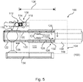
- Fig. 5 schematically shows a top view of an operating room arrangement 100 with a laminar airflow.
- the operating room arrangement 100 comprises at least a ceiling region 102, not further shown.
- the operating room arrangement further comprises a laminar airflow system 104, also not further shown and a medical imaging system 106.
- the laminar airflow system 104 comprises at least one laminar airflow outlet 108 configured to provide at least one laminar airflow plenum 110.
- the medical imaging system 106 comprises an image acquisition arrangement 112 with a source 114 and a detector 116.
- the image acquisition arrangement may be provided as an X-ray imaging apparatus.
- the medical imaging system 106 comprises a support arrangement 118 with at least one support rail 120 mounted in the ceiling region and a carriage 122 that is movable along at least a part of the support rail 120. At least one of the source and detector is movably supported by the carriage. At least a part of the at least one support rail is arranged downstream the laminar airflow outlet. At least one rail cover 124 for covering at least one part of the support rail is provided.
- the rail cover is provided as an aerodynamic rail cover according to one of the examples above.
- the at least one laminar airflow outlet is configured to provide an airflow towards a patient table 126.
- two cover segments 128, 130 are provided for each rail.
- One of the two cover segments is fixedly mounted to the support rail to provide a fixed rail cover segment, and the other of the two cover segments is arranged on the rail in a displaceable manner.
- the cover segment can temporarily be moved away and moved back in place later.
- an adjustable rail cover segment is provided.
- the cover segment 128 is movable, as indicated with arrow 132.
- the cover segment 130 is fixed.
- the adjustable rail cover segment is provided as a movable cover segment.
- the movable cover segment 128 is at least partly insertable into the fixed rail cover segment 130, as indicated in Figs. 6a and 6b .
- the fixed rail cover segment is at least partly insertable into the movable cover segment.
- the two cover segments are forming a telescopic cover component.
- FIG. 5 also further equipment such as a ceiling suspended display (not shown in detail) and an interface arrangement 134 is indicated.
- a ceiling suspended display not shown in detail
- an interface arrangement 134 is indicated.
- an arrow 136 indicates a longitudinal range in which the carriage 122 can be moved along the rails 120.
- An arrow 138 indicates the movability of the carriage 122 along the rails 120.
- the movable cover segment 128 can be referred to as movable ARC
- the fixed cover segment 130 can be referred to as fixed ARC docks.
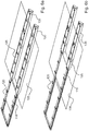
- Figs. 6a and 6b show a rail arrangement with rail covers resulting in an adaptable field of laminar airflow.
- Fig. 6a shows a carriage for an X-ray imaging system in a first position
- Fig. 6b shows the carriage in a second position with displaced cover segments.
- the rail cover component is an adaptable rail cover component comprising at least one telescopic cover segment with a plurality of telescopic cover elements.
- the rail cover component is an adaptable rail cover component comprising at least one bellows cover segment.
- one end of the adaptable cover component is configured to be fixed, whereas the other end is configured to be displaceable providing a rail cover component with adaptable length.
- the cover is a harmonic folding rail cover.
- the ARC length can be varied by compression or expansion of a flexible bag (like a bellow) which covers the rail.
- the outer contour of the folding ARC is similar shaped as described above and below, but consists of small segments which can fold against each other (compressed) or unfolded (expanded).
- a laminar airflow system for an operating room with a medical imaging system.
- the airflow system comprises at least one laminar airflow outlet configured to provide at least one laminar airflow plenum.
- the at least one laminar airflow outlet is configured to provide an airflow towards a patient table.
- a support rail of a ceiling mounted support arrangement of a medical imaging system can be arranged downstream the laminar airflow outlet or adjacent to the laminar airflow plenum.
- At least one rail cover for covering at least one part of the support rail is provided, which rail cover is provided as an aerodynamic rail cover according to one of the above and below described examples.
- laminar airflow plenum refers to an area within the operating room where laminar airflow is provided from the ceiling down onto a predefined area plenum of operation.
- the laminar airflow is preferably providing a flow of clean air, e.g. sterile air. This helps in minimizing the risk of infection of the patient due to contaminated air from the e.g. surrounding.
- a medical imaging system for an operating room with laminar airflow comprises an image acquisition arrangement with a source and a detector.
- the imaging system further comprises a ceiling mounted support arrangement with at least one support rail and a carriage movable along at least a part of the support rail.
- the imaging system further comprises at least one rail cover for covering at least one part of the support rail.
- At least one of the source and detector is movably supported by the carriage.
- At least a part of the at least one support rail can be arranged downstream a laminar airflow outlet or adjacent to a laminar airflow plenum provided by the laminar airflow outlet.
- the rail cover is provided as an aerodynamic rail cover according to one of the above and below described examples.
- Fig. 7 schematically shows a perspective view of an operating room 140 with a medical imaging system 142 and laminar airflow system 144. Rails (covered by the aerodynamic rail cover) are arranged in ceiling plane. A patient table 146 is provided, together with further imaging or examination equipment. The aerodynamic rail covers, indicated with reference number 148, result in that a continuous field of laminar airflow is provided in the level of the patient table due to the recombining of the two adjacent fields of laminar downflow.
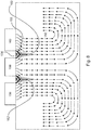
- Fig. 8 illustrates a vertical cross section of a flow field simulation 150 with two rail covers 152 arranged in parts with ceiling mounted rails 154.
- Three boxes 156, 158, 160 for generating a laminar airflow field below are arranged. The area below the boxes is separated by the two rails 154.
- the two rail covers 152 as aerodynamic rail covers, re-established laminar airflow 162 below the rails is provided.
- the laminar downflow provides an area for the operating table which area can be supplied with pre-treated or pre-conditioned. Surrounding air does not enter the laminar flow field. In the blocked areas, where the rails are provided, the aerodynamic rail covers result in the re-established laminar air flow.
- Fig. 9 shows a method 200 for providing a laminar airflow for an operating room. The method comprises the following steps:
Landscapes
- Health & Medical Sciences (AREA)
- Life Sciences & Earth Sciences (AREA)
- Engineering & Computer Science (AREA)
- Veterinary Medicine (AREA)
- Public Health (AREA)
- General Health & Medical Sciences (AREA)
- Animal Behavior & Ethology (AREA)
- Medical Informatics (AREA)
- Biomedical Technology (AREA)
- Surgery (AREA)
- High Energy & Nuclear Physics (AREA)
- Radiology & Medical Imaging (AREA)
- Heart & Thoracic Surgery (AREA)
- Molecular Biology (AREA)
- Pathology (AREA)
- Optics & Photonics (AREA)
- Nuclear Medicine, Radiotherapy & Molecular Imaging (AREA)
- Physics & Mathematics (AREA)
- Biophysics (AREA)
- Nursing (AREA)
- Accommodation For Nursing Or Treatment Tables (AREA)
- Apparatus For Radiation Diagnosis (AREA)
Priority Applications (7)
| Application Number | Priority Date | Filing Date | Title |
|---|---|---|---|
| EP17208895.7A EP3501472A1 (de) | 2017-12-20 | 2017-12-20 | Aerodynamische schienenabdeckungen |
| US16/955,853 US11576831B2 (en) | 2017-12-20 | 2018-12-12 | Aerodynamic rail covers |
| EP18826221.6A EP3727269B1 (de) | 2017-12-20 | 2018-12-12 | Aerodynamische schienenabdeckungen |
| CN201880081686.8A CN111491598B (zh) | 2017-12-20 | 2018-12-12 | 气动导轨罩盖 |
| JP2020533223A JP7208998B2 (ja) | 2017-12-20 | 2018-12-12 | 空気力学的レールカバー |
| PCT/EP2018/084425 WO2019121181A1 (en) | 2017-12-20 | 2018-12-12 | Aerodynamic rail covers |
| US18/086,723 US11872165B2 (en) | 2017-12-20 | 2022-12-22 | Aerodynamic rail covers |
Applications Claiming Priority (1)
| Application Number | Priority Date | Filing Date | Title |
|---|---|---|---|
| EP17208895.7A EP3501472A1 (de) | 2017-12-20 | 2017-12-20 | Aerodynamische schienenabdeckungen |
Publications (1)
| Publication Number | Publication Date |
|---|---|
| EP3501472A1 true EP3501472A1 (de) | 2019-06-26 |
Family
ID=60702359
Family Applications (2)
| Application Number | Title | Priority Date | Filing Date |
|---|---|---|---|
| EP17208895.7A Withdrawn EP3501472A1 (de) | 2017-12-20 | 2017-12-20 | Aerodynamische schienenabdeckungen |
| EP18826221.6A Active EP3727269B1 (de) | 2017-12-20 | 2018-12-12 | Aerodynamische schienenabdeckungen |
Family Applications After (1)
| Application Number | Title | Priority Date | Filing Date |
|---|---|---|---|
| EP18826221.6A Active EP3727269B1 (de) | 2017-12-20 | 2018-12-12 | Aerodynamische schienenabdeckungen |
Country Status (5)
| Country | Link |
|---|---|
| US (2) | US11576831B2 (de) |
| EP (2) | EP3501472A1 (de) |
| JP (1) | JP7208998B2 (de) |
| CN (1) | CN111491598B (de) |
| WO (1) | WO2019121181A1 (de) |
Families Citing this family (1)
| Publication number | Priority date | Publication date | Assignee | Title |
|---|---|---|---|---|
| EP3501472A1 (de) * | 2017-12-20 | 2019-06-26 | Koninklijke Philips N.V. | Aerodynamische schienenabdeckungen |
Citations (3)
| Publication number | Priority date | Publication date | Assignee | Title |
|---|---|---|---|---|
| US4946484A (en) * | 1988-02-05 | 1990-08-07 | Donaldson Company, Inc. | Support for clean room ceiling grid system |
| WO2016116389A1 (en) | 2015-01-20 | 2016-07-28 | Koninklijke Philips N.V. | Medical imaging with integrated air guidance |
| CN107355970A (zh) * | 2017-08-25 | 2017-11-17 | 安徽省伟业净化设备有限公司 | 一种组合式低噪音百级层流系统 |
Family Cites Families (19)
| Publication number | Priority date | Publication date | Assignee | Title |
|---|---|---|---|---|
| JPS61276644A (ja) * | 1985-05-14 | 1986-12-06 | フランダ−ス・フイルタ−ズ・インコ−ポレイテツド | 層流式清浄室 |
| JPH03502349A (ja) * | 1988-02-05 | 1991-05-30 | ダナルドスン、カムパニ、インコーパレイティド | クリーンルーム天井格子システム |
| JPH01210749A (ja) | 1988-02-18 | 1989-08-24 | Shimizu Corp | クリーンルーム内ロボット用走行部ダクト |
| JP3051094U (ja) | 1998-01-28 | 1998-08-11 | 有限会社ユタカ工業 | クリーンルーム用天井構成材 |
| ATE516789T1 (de) * | 2003-03-28 | 2011-08-15 | Medical Technology Transfer Holding B V | Operationseinheit |
| US7534036B2 (en) * | 2006-10-25 | 2009-05-19 | General Electric Company | Method and arrangement for a mobile imaging system |
| US20100120349A1 (en) * | 2008-10-31 | 2010-05-13 | Airsonett Ab | Surgical theater ventilating devices and methods |
| FR2953119B1 (fr) * | 2009-12-01 | 2012-07-27 | Gen Electric | Base mobile et appareil a rayons x monte sur une telle base mobile |
| US8814067B2 (en) * | 2011-04-28 | 2014-08-26 | Maxum Llc | Optimized air delivery apparatus |
| WO2014111437A1 (en) * | 2013-01-17 | 2014-07-24 | Koninklijke Philips N.V. | Ceiling suspension system |
| DE102013220282A1 (de) * | 2013-10-08 | 2015-04-09 | Siemens Aktiengesellschaft | Vorrichtung mit zumindest einem Kanal und zumindest zwei Flüssigkeiten |
| CN203824012U (zh) * | 2013-12-16 | 2014-09-10 | 中国中元国际工程有限公司 | 洁净手术室 |
| CN104713211B (zh) * | 2013-12-16 | 2017-11-10 | 中国中元国际工程有限公司 | 洁净手术室 |
| JP6191485B2 (ja) | 2014-02-03 | 2017-09-06 | 富士電機株式会社 | 冷蔵倉庫 |
| US11186989B2 (en) * | 2015-10-07 | 2021-11-30 | Sld Technology, Inc. | Equipment support system and method of supporting equipment |
| JP6740847B2 (ja) | 2015-11-06 | 2020-08-19 | 株式会社大林組 | 空調システム |
| DE102016208123B4 (de) * | 2016-05-11 | 2020-03-19 | Siemens Healthcare Gmbh | Verfahren und System zum Ausführen einer Scanbewegung einer Bildgebungsdaten-Akquisitionseinheit |
| EP3417788B1 (de) * | 2017-06-21 | 2020-03-25 | Siemens Healthcare GmbH | Gantry für eine medizinische bildgebungsvorrichtung und verfahren zur luftkühlung zumindest einer komponente der gantry |
| EP3501472A1 (de) * | 2017-12-20 | 2019-06-26 | Koninklijke Philips N.V. | Aerodynamische schienenabdeckungen |
-
2017
- 2017-12-20 EP EP17208895.7A patent/EP3501472A1/de not_active Withdrawn
-
2018
- 2018-12-12 US US16/955,853 patent/US11576831B2/en active Active
- 2018-12-12 EP EP18826221.6A patent/EP3727269B1/de active Active
- 2018-12-12 WO PCT/EP2018/084425 patent/WO2019121181A1/en not_active Ceased
- 2018-12-12 JP JP2020533223A patent/JP7208998B2/ja active Active
- 2018-12-12 CN CN201880081686.8A patent/CN111491598B/zh active Active
-
2022
- 2022-12-22 US US18/086,723 patent/US11872165B2/en active Active
Patent Citations (3)
| Publication number | Priority date | Publication date | Assignee | Title |
|---|---|---|---|---|
| US4946484A (en) * | 1988-02-05 | 1990-08-07 | Donaldson Company, Inc. | Support for clean room ceiling grid system |
| WO2016116389A1 (en) | 2015-01-20 | 2016-07-28 | Koninklijke Philips N.V. | Medical imaging with integrated air guidance |
| CN107355970A (zh) * | 2017-08-25 | 2017-11-17 | 安徽省伟业净化设备有限公司 | 一种组合式低噪音百级层流系统 |
Also Published As
| Publication number | Publication date |
|---|---|
| US11576831B2 (en) | 2023-02-14 |
| EP3727269A1 (de) | 2020-10-28 |
| US20230130118A1 (en) | 2023-04-27 |
| JP7208998B2 (ja) | 2023-01-19 |
| EP3727269B1 (de) | 2024-02-07 |
| JP2021506435A (ja) | 2021-02-22 |
| CN111491598B (zh) | 2022-12-27 |
| US11872165B2 (en) | 2024-01-16 |
| WO2019121181A1 (en) | 2019-06-27 |
| CN111491598A (zh) | 2020-08-04 |
| US20200315893A1 (en) | 2020-10-08 |
Similar Documents
| Publication | Publication Date | Title |
|---|---|---|
| US10842451B2 (en) | Medical imaging with integrated air guidance | |
| US4140105A (en) | Gas curtain for shielding person on an operating table | |
| US20190234645A1 (en) | Sterile airflow delivery system | |
| US11872165B2 (en) | Aerodynamic rail covers | |
| CN108592290B (zh) | 一种用于进行隔离的防护装置 | |
| CN102271586A (zh) | 用于x射线检查装置的支架 | |
| DE202020102737U1 (de) | Infektionsschutzvorrichtung zum Infektionsschutz von einer und/oder vor einer Person bzgl. Pathogene | |
| WO2017058507A2 (en) | Portable, controlled environment system | |
| JP2014176787A (ja) | 除塵ブース | |
| JP6153128B2 (ja) | 手術室用照明装置及びこれを備えた手術室 | |
| US9980688B2 (en) | Ceiling suspension system | |
| JP2016502926A5 (de) | ||
| DE102020121450B4 (de) | Vorrichtung zum Schutz vor Übertragung von Krankheitserregern durch Aerosole in geschlossenen Räumen | |
| ES2876051A1 (es) | Procedimiento de proteccion para reducir el contagio interpersonal mediado por particulas o aerosoles respiratorios basado en un flujo de aire descendente | |
| EP4366676A1 (de) | Chirurgische operationseinheit mit lokalem operationsfeld | |
| DE2512679A1 (de) | Einrichtung zur belueftung von operationsraeumen | |
| CN213489925U (zh) | 一种防护隔离病床 | |
| WO2008004925A1 (en) | Air filter for clean rooms including inclined filter elements | |
| JP7732847B2 (ja) | 座席アセンブリ用のヘッドレスト換気システム及び方法 | |
| EP2110615A2 (de) | Sterilkabine | |
| WO2022063948A1 (en) | Air purification system | |
| JP2024016717A (ja) | プッシュ型送風装置及びそれを用いた空間分離装置 | |
| SE422274B (sv) | Luftutsugningssystem vid operationsbord der narkos ges med narkosmask |
Legal Events
| Date | Code | Title | Description |
|---|---|---|---|
| PUAI | Public reference made under article 153(3) epc to a published international application that has entered the european phase |
Free format text: ORIGINAL CODE: 0009012 |
|
| AK | Designated contracting states |
Kind code of ref document: A1 Designated state(s): AL AT BE BG CH CY CZ DE DK EE ES FI FR GB GR HR HU IE IS IT LI LT LU LV MC MK MT NL NO PL PT RO RS SE SI SK SM TR |
|
| AX | Request for extension of the european patent |
Extension state: BA ME |
|
| RAP1 | Party data changed (applicant data changed or rights of an application transferred) |
Owner name: KONINKLIJKE PHILIPS N.V. |
|
| STAA | Information on the status of an ep patent application or granted ep patent |
Free format text: STATUS: THE APPLICATION IS DEEMED TO BE WITHDRAWN |
|
| 18D | Application deemed to be withdrawn |
Effective date: 20200103 |