EP3501594A2 - Système et procédé de connexion stérile des passages de fluide - Google Patents
Système et procédé de connexion stérile des passages de fluide Download PDFInfo
- Publication number
- EP3501594A2 EP3501594A2 EP18214466.7A EP18214466A EP3501594A2 EP 3501594 A2 EP3501594 A2 EP 3501594A2 EP 18214466 A EP18214466 A EP 18214466A EP 3501594 A2 EP3501594 A2 EP 3501594A2
- Authority
- EP
- European Patent Office
- Prior art keywords
- connector
- chamber
- opening
- open
- closed configuration
- Prior art date
- Legal status (The legal status is an assumption and is not a legal conclusion. Google has not performed a legal analysis and makes no representation as to the accuracy of the status listed.)
- Granted
Links
Images







Classifications
-
- A—HUMAN NECESSITIES
- A61—MEDICAL OR VETERINARY SCIENCE; HYGIENE
- A61M—DEVICES FOR INTRODUCING MEDIA INTO, OR ONTO, THE BODY; DEVICES FOR TRANSDUCING BODY MEDIA OR FOR TAKING MEDIA FROM THE BODY; DEVICES FOR PRODUCING OR ENDING SLEEP OR STUPOR
- A61M39/00—Tubes, tube connectors, tube couplings, valves, access sites or the like, specially adapted for medical use
- A61M39/10—Tube connectors; Tube couplings
- A61M39/16—Tube connectors; Tube couplings having provision for disinfection or sterilisation
- A61M39/18—Methods or apparatus for making the connection under sterile conditions, i.e. sterile docking
-
- A—HUMAN NECESSITIES
- A61—MEDICAL OR VETERINARY SCIENCE; HYGIENE
- A61L—METHODS OR APPARATUS FOR STERILISING MATERIALS OR OBJECTS IN GENERAL; DISINFECTION, STERILISATION OR DEODORISATION OF AIR; CHEMICAL ASPECTS OF BANDAGES, DRESSINGS, ABSORBENT PADS OR SURGICAL ARTICLES; MATERIALS FOR BANDAGES, DRESSINGS, ABSORBENT PADS OR SURGICAL ARTICLES
- A61L2/00—Disinfection or sterilisation of materials or objects, in general; Accessories therefor
- A61L2/02—Disinfection or sterilisation of materials or objects, in general; Accessories therefor using physical processes
- A61L2/04—Heat
-
- A—HUMAN NECESSITIES
- A61—MEDICAL OR VETERINARY SCIENCE; HYGIENE
- A61L—METHODS OR APPARATUS FOR STERILISING MATERIALS OR OBJECTS IN GENERAL; DISINFECTION, STERILISATION OR DEODORISATION OF AIR; CHEMICAL ASPECTS OF BANDAGES, DRESSINGS, ABSORBENT PADS OR SURGICAL ARTICLES; MATERIALS FOR BANDAGES, DRESSINGS, ABSORBENT PADS OR SURGICAL ARTICLES
- A61L2/00—Disinfection or sterilisation of materials or objects, in general; Accessories therefor
- A61L2/02—Disinfection or sterilisation of materials or objects, in general; Accessories therefor using physical processes
- A61L2/04—Heat
- A61L2/06—Hot gas
- A61L2/07—Steam
-
- A—HUMAN NECESSITIES
- A61—MEDICAL OR VETERINARY SCIENCE; HYGIENE
- A61L—METHODS OR APPARATUS FOR STERILISING MATERIALS OR OBJECTS IN GENERAL; DISINFECTION, STERILISATION OR DEODORISATION OF AIR; CHEMICAL ASPECTS OF BANDAGES, DRESSINGS, ABSORBENT PADS OR SURGICAL ARTICLES; MATERIALS FOR BANDAGES, DRESSINGS, ABSORBENT PADS OR SURGICAL ARTICLES
- A61L2/00—Disinfection or sterilisation of materials or objects, in general; Accessories therefor
- A61L2/02—Disinfection or sterilisation of materials or objects, in general; Accessories therefor using physical processes
- A61L2/08—Radiation
- A61L2/081—Gamma radiation
-
- A—HUMAN NECESSITIES
- A61—MEDICAL OR VETERINARY SCIENCE; HYGIENE
- A61L—METHODS OR APPARATUS FOR STERILISING MATERIALS OR OBJECTS IN GENERAL; DISINFECTION, STERILISATION OR DEODORISATION OF AIR; CHEMICAL ASPECTS OF BANDAGES, DRESSINGS, ABSORBENT PADS OR SURGICAL ARTICLES; MATERIALS FOR BANDAGES, DRESSINGS, ABSORBENT PADS OR SURGICAL ARTICLES
- A61L2/00—Disinfection or sterilisation of materials or objects, in general; Accessories therefor
- A61L2/02—Disinfection or sterilisation of materials or objects, in general; Accessories therefor using physical processes
- A61L2/08—Radiation
- A61L2/087—Particle radiation, e.g. electron-beam, alpha or beta radiation
-
- A—HUMAN NECESSITIES
- A61—MEDICAL OR VETERINARY SCIENCE; HYGIENE
- A61L—METHODS OR APPARATUS FOR STERILISING MATERIALS OR OBJECTS IN GENERAL; DISINFECTION, STERILISATION OR DEODORISATION OF AIR; CHEMICAL ASPECTS OF BANDAGES, DRESSINGS, ABSORBENT PADS OR SURGICAL ARTICLES; MATERIALS FOR BANDAGES, DRESSINGS, ABSORBENT PADS OR SURGICAL ARTICLES
- A61L2/00—Disinfection or sterilisation of materials or objects, in general; Accessories therefor
- A61L2/02—Disinfection or sterilisation of materials or objects, in general; Accessories therefor using physical processes
- A61L2/08—Radiation
- A61L2/10—Ultraviolet [UV] radiation
-
- A—HUMAN NECESSITIES
- A61—MEDICAL OR VETERINARY SCIENCE; HYGIENE
- A61M—DEVICES FOR INTRODUCING MEDIA INTO, OR ONTO, THE BODY; DEVICES FOR TRANSDUCING BODY MEDIA OR FOR TAKING MEDIA FROM THE BODY; DEVICES FOR PRODUCING OR ENDING SLEEP OR STUPOR
- A61M1/00—Suction or pumping devices for medical purposes; Devices for carrying-off, for treatment of, or for carrying-over, body-liquids; Drainage systems
- A61M1/02—Blood transfusion apparatus
- A61M1/0209—Multiple bag systems for separating or storing blood components
-
- A—HUMAN NECESSITIES
- A61—MEDICAL OR VETERINARY SCIENCE; HYGIENE
- A61M—DEVICES FOR INTRODUCING MEDIA INTO, OR ONTO, THE BODY; DEVICES FOR TRANSDUCING BODY MEDIA OR FOR TAKING MEDIA FROM THE BODY; DEVICES FOR PRODUCING OR ENDING SLEEP OR STUPOR
- A61M1/00—Suction or pumping devices for medical purposes; Devices for carrying-off, for treatment of, or for carrying-over, body-liquids; Drainage systems
- A61M1/02—Blood transfusion apparatus
- A61M1/025—Means for agitating or shaking blood containers
-
- A—HUMAN NECESSITIES
- A61—MEDICAL OR VETERINARY SCIENCE; HYGIENE
- A61M—DEVICES FOR INTRODUCING MEDIA INTO, OR ONTO, THE BODY; DEVICES FOR TRANSDUCING BODY MEDIA OR FOR TAKING MEDIA FROM THE BODY; DEVICES FOR PRODUCING OR ENDING SLEEP OR STUPOR
- A61M39/00—Tubes, tube connectors, tube couplings, valves, access sites or the like, specially adapted for medical use
- A61M39/10—Tube connectors; Tube couplings
- A61M39/105—Multi-channel connectors or couplings, e.g. for connecting multi-lumen tubes
-
- A—HUMAN NECESSITIES
- A61—MEDICAL OR VETERINARY SCIENCE; HYGIENE
- A61M—DEVICES FOR INTRODUCING MEDIA INTO, OR ONTO, THE BODY; DEVICES FOR TRANSDUCING BODY MEDIA OR FOR TAKING MEDIA FROM THE BODY; DEVICES FOR PRODUCING OR ENDING SLEEP OR STUPOR
- A61M39/00—Tubes, tube connectors, tube couplings, valves, access sites or the like, specially adapted for medical use
- A61M39/10—Tube connectors; Tube couplings
- A61M39/1055—Rotating or swivel joints
-
- A—HUMAN NECESSITIES
- A61—MEDICAL OR VETERINARY SCIENCE; HYGIENE
- A61M—DEVICES FOR INTRODUCING MEDIA INTO, OR ONTO, THE BODY; DEVICES FOR TRANSDUCING BODY MEDIA OR FOR TAKING MEDIA FROM THE BODY; DEVICES FOR PRODUCING OR ENDING SLEEP OR STUPOR
- A61M39/00—Tubes, tube connectors, tube couplings, valves, access sites or the like, specially adapted for medical use
- A61M39/22—Valves or arrangement of valves
- A61M39/26—Valves closing automatically on disconnecting the line and opening on reconnection thereof
-
- B—PERFORMING OPERATIONS; TRANSPORTING
- B08—CLEANING
- B08B—CLEANING IN GENERAL; PREVENTION OF FOULING IN GENERAL
- B08B7/00—Cleaning by methods not provided for in a single other subclass or a single group in this subclass
- B08B7/0035—Cleaning by methods not provided for in a single other subclass or a single group in this subclass by radiant energy, e.g. UV, laser, light beam or the like
- B08B7/0057—Cleaning by methods not provided for in a single other subclass or a single group in this subclass by radiant energy, e.g. UV, laser, light beam or the like by ultraviolet radiation
-
- B—PERFORMING OPERATIONS; TRANSPORTING
- B08—CLEANING
- B08B—CLEANING IN GENERAL; PREVENTION OF FOULING IN GENERAL
- B08B9/00—Cleaning hollow articles by methods or apparatus specially adapted thereto
- B08B9/02—Cleaning pipes or tubes or systems of pipes or tubes
- B08B9/021—Cleaning pipe ends or pipe fittings, e.g. before soldering
-
- B—PERFORMING OPERATIONS; TRANSPORTING
- B08—CLEANING
- B08B—CLEANING IN GENERAL; PREVENTION OF FOULING IN GENERAL
- B08B9/00—Cleaning hollow articles by methods or apparatus specially adapted thereto
- B08B9/02—Cleaning pipes or tubes or systems of pipes or tubes
- B08B9/027—Cleaning the internal surfaces; Removal of blockages
-
- A—HUMAN NECESSITIES
- A61—MEDICAL OR VETERINARY SCIENCE; HYGIENE
- A61M—DEVICES FOR INTRODUCING MEDIA INTO, OR ONTO, THE BODY; DEVICES FOR TRANSDUCING BODY MEDIA OR FOR TAKING MEDIA FROM THE BODY; DEVICES FOR PRODUCING OR ENDING SLEEP OR STUPOR
- A61M39/00—Tubes, tube connectors, tube couplings, valves, access sites or the like, specially adapted for medical use
- A61M39/10—Tube connectors; Tube couplings
- A61M2039/1033—Swivel nut connectors, e.g. threaded connectors, bayonet-connectors
-
- A—HUMAN NECESSITIES
- A61—MEDICAL OR VETERINARY SCIENCE; HYGIENE
- A61M—DEVICES FOR INTRODUCING MEDIA INTO, OR ONTO, THE BODY; DEVICES FOR TRANSDUCING BODY MEDIA OR FOR TAKING MEDIA FROM THE BODY; DEVICES FOR PRODUCING OR ENDING SLEEP OR STUPOR
- A61M39/00—Tubes, tube connectors, tube couplings, valves, access sites or the like, specially adapted for medical use
- A61M39/10—Tube connectors; Tube couplings
- A61M2039/1038—Union screw connectors, e.g. hollow screw or sleeve having external threads
-
- A—HUMAN NECESSITIES
- A61—MEDICAL OR VETERINARY SCIENCE; HYGIENE
- A61M—DEVICES FOR INTRODUCING MEDIA INTO, OR ONTO, THE BODY; DEVICES FOR TRANSDUCING BODY MEDIA OR FOR TAKING MEDIA FROM THE BODY; DEVICES FOR PRODUCING OR ENDING SLEEP OR STUPOR
- A61M39/00—Tubes, tube connectors, tube couplings, valves, access sites or the like, specially adapted for medical use
- A61M39/10—Tube connectors; Tube couplings
- A61M39/16—Tube connectors; Tube couplings having provision for disinfection or sterilisation
- A61M2039/167—Tube connectors; Tube couplings having provision for disinfection or sterilisation with energizing means, e.g. light, vibration, electricity
-
- A—HUMAN NECESSITIES
- A61—MEDICAL OR VETERINARY SCIENCE; HYGIENE
- A61M—DEVICES FOR INTRODUCING MEDIA INTO, OR ONTO, THE BODY; DEVICES FOR TRANSDUCING BODY MEDIA OR FOR TAKING MEDIA FROM THE BODY; DEVICES FOR PRODUCING OR ENDING SLEEP OR STUPOR
- A61M39/00—Tubes, tube connectors, tube couplings, valves, access sites or the like, specially adapted for medical use
- A61M39/22—Valves or arrangement of valves
- A61M39/26—Valves closing automatically on disconnecting the line and opening on reconnection thereof
- A61M2039/261—Valves closing automatically on disconnecting the line and opening on reconnection thereof where the fluid space within the valve is increasing upon disconnection
-
- A—HUMAN NECESSITIES
- A61—MEDICAL OR VETERINARY SCIENCE; HYGIENE
- A61M—DEVICES FOR INTRODUCING MEDIA INTO, OR ONTO, THE BODY; DEVICES FOR TRANSDUCING BODY MEDIA OR FOR TAKING MEDIA FROM THE BODY; DEVICES FOR PRODUCING OR ENDING SLEEP OR STUPOR
- A61M39/00—Tubes, tube connectors, tube couplings, valves, access sites or the like, specially adapted for medical use
- A61M39/22—Valves or arrangement of valves
- A61M39/26—Valves closing automatically on disconnecting the line and opening on reconnection thereof
- A61M2039/263—Valves closing automatically on disconnecting the line and opening on reconnection thereof where the fluid space within the valve is decreasing upon disconnection
-
- A—HUMAN NECESSITIES
- A61—MEDICAL OR VETERINARY SCIENCE; HYGIENE
- A61M—DEVICES FOR INTRODUCING MEDIA INTO, OR ONTO, THE BODY; DEVICES FOR TRANSDUCING BODY MEDIA OR FOR TAKING MEDIA FROM THE BODY; DEVICES FOR PRODUCING OR ENDING SLEEP OR STUPOR
- A61M39/00—Tubes, tube connectors, tube couplings, valves, access sites or the like, specially adapted for medical use
- A61M39/22—Valves or arrangement of valves
- A61M39/26—Valves closing automatically on disconnecting the line and opening on reconnection thereof
- A61M2039/267—Valves closing automatically on disconnecting the line and opening on reconnection thereof having a sealing sleeve around a tubular or solid stem portion of the connector
- A61M2039/268—Valves closing automatically on disconnecting the line and opening on reconnection thereof having a sealing sleeve around a tubular or solid stem portion of the connector wherein the stem portion is moved for opening and closing the valve, e.g. by translation, rotation
-
- B—PERFORMING OPERATIONS; TRANSPORTING
- B08—CLEANING
- B08B—CLEANING IN GENERAL; PREVENTION OF FOULING IN GENERAL
- B08B2209/00—Details of machines or methods for cleaning hollow articles
- B08B2209/02—Details of apparatuses or methods for cleaning pipes or tubes
- B08B2209/027—Details of apparatuses or methods for cleaning pipes or tubes for cleaning the internal surfaces
-
- B—PERFORMING OPERATIONS; TRANSPORTING
- B08—CLEANING
- B08B—CLEANING IN GENERAL; PREVENTION OF FOULING IN GENERAL
- B08B2230/00—Other cleaning aspects applicable to all B08B range
- B08B2230/01—Cleaning with steam
Definitions
- the present disclosure relates generally to systems and methods of sterilely connecting fluid pathways and, in particular to systems and methods for sterilely connecting fluid pathways with a reusable connector within a biological fluid circuit without excising fluid pathway material.
- Processing or collection of biological fluid such as blood components, biological fluids, or medical fluids may involve using a reusable hardware and a disposable fluid circuit adapted for mounting or other association with the reusable hardware.
- the fluid circuit may include containers such as plastic containers, vials, and associated tubing that define flow paths through the circuit.
- a disposable fluid circuit may include plastic containers and tubes that are pre-connected and pre-assembled to maintain sterility.
- containers including liquids such as anticoagulant, saline, wash solution, storage media, treating agents, biological fluids, etc., may likewise be pre-attached to the disposable fluid circuit, thereby creating a "closed” system.
- a "closed” system is one where the interior of the system, i.e., internal flow paths, separation chambers, etc., are not exposed or “opened” to the outside environment.
- the present disclosure is directed to a tube connector for a fluid circuit system comprising a housing.
- a first opening is configured to receive a first length of tubing in communication with a first chamber.
- a second opening is configured for communicating with the first chamber when the tube connector is in an open configuration but not in a closed configuration.
- a third opening is configured to receive a second length of tubing in communication with a second chamber.
- a fourth opening is configured for communicating with the second chamber when the tube connector is in the open configuration but not in the closed configuration. The second opening and the fourth opening are configured to engage each other to form a third chamber.
- the present disclosure is directed to a method of sterilely connecting two fluid pathways.
- a first connector comprising a first chamber and a first open end and configured to connect to a first fluid pathway.
- the first chamber is configured to communicate with the first fluid pathway and the first open end when the first connector is in an open configuration but not in a closed configuration.
- a second connector comprising a second chamber and a second open end and configured to connect to a second fluid pathway.
- the second chamber is configured to communicate with the second fluid pathway and the second open end when the second connector is in an open configuration but not in a closed configuration.
- the first open end and the second open end are configured for engagement to form a third chamber.
- the third chamber is configured to communicate with the first chamber when the first connector is in the open configuration but not in the closed configuration and communicate with the second chamber when the second connector is in the open configuration but not in the closed configuration.
- the first open end and the second open end forming the third chamber comprises a first material at least partially permeable to a sterilization energy source for sterilizing contents of the third chamber.
- a first portion of the first connector surrounding the first chamber and a second portion of the second connector surrounding the second chamber comprise a second material less permeable to the sterilization energy source.
- the present disclosure is directed to a sterile tube connector for a fluid circuit system comprising a housing.
- a first opening is configured to receive a first length of tubing in communication with a first chamber.
- a second opening is configured for communicating with the first chamber when the tube connector is in an open configuration but not in a closed configuration.
- the second opening is configured to reversibly engage a third opening to form a second chamber.
- the third opening is configured for communicating with a second length of tubing.
- a first portion of the housing forming the first opening comprises a material at least partially permeable to a sterilization energy source for sterilizing contents of the second chamber.
- a sterile weld device which takes two tubing segments of compatible sizes and materials and performs a welding operation in which the segments of tubing are clamped, cut, aligned with each other, and melted to fuse the two segments together.
- An operator may manually load tubing segments into the sterile weld device serially for each welding operation.
- a sterile weld device may require additional disposable components, e.g., blades, cartridges, and may include some portion of a tubing segment being excised, thereby shortening the tubing segment with each sterile weld operation.
- additional disposable components e.g., blades, cartridges
- sterile welding may call for each circuit to have long lengths of tubing to accommodate tubing length consumption with each welding event.
- Some embodiments may decrease reliance on manual interventions common even in automated processes of multiple welding operations involving complex loading and unloading procedures.
- Some embodiments may minimize or obviate tracking tubing lengths being consumed for multiply-welded tubing segments.
- Some embodiments may enable fluid circuit connections even when the segments to be connected are not made of compatible materials or employ dissimilar sizes or are otherwise not easily implemented with welding systems.”
- Some embodiments may obviate the use of additional disposable components in sterilely connecting fluid pathways together.
- Some embodiments may allow for repeated sterile connections between two fluid pathway segments without shortening segment lengths each time the connection is performed.
- Some embodiments may allow fluid circuits to have shorter lengths of tubing without accommodating tubing length consumption with each welding event.
- Some embodiments may decrease variability in the pathway joining process and be conducive to automation.
- the systems disclosed may include a fluid processing apparatus and one or more disposable processing circuits adapted for association with the processing apparatus.
- the processing apparatus may be any apparatus for processing of fluids in sterile environments. Examples include apparatuses for cell processing, apheresis, infusion, transfusion, fractionation, cell washing, dialysis, molecular and medical diagnostics, forensics, anesthesia, etc.
- the processing apparatus may be capable of effecting the separation of a biological fluid that includes biological cells into two or more components or fractions. Thus, the processing apparatus may generate conditions which allow for the separation of a biological fluid into selected components or fractions.
- an apparatus that uses a spinning porous membrane to separate one component from other components may be used for separating biological fluid into its constituent components or fractions.
- An example of a spinning membrane may be found in U.S. Patent No. 5,194,145 to Schoendorfer and International Application No.
- Both membrane separation and centrifugal separation systems may involve a durable processing system or device used in combination with a disposable processing set or circuit.
- the durable processing system may include a pump assembly that interacts with one or more of the components of the disposable circuit to draw blood or other bodily fluid from a blood source and move the blood or bodily fluid to another location within the disposable circuit by moving fluid through a fluid flow path.
- fluid circuit 100 may be configured to associate with a cell processing machine 200 ( Fig. 2 ) that separates source blood into blood components.
- a cell processing device 200 may include a membrane separator 35 or other blood separation device that processes whole blood or other suspensions of biological material into its constituent components (e.g., red blood cells, plasma, platelets, etc.).
- the cell processing device may associate with fluid circuit 100 which may be configured to convey fluid to and from the separator or other separation device to/from/between multiple collection containers 440, 510, 550.
- Such fluids may be routed in fluid circuit 100 via lengths of fluid pathways or tubing 150a-j.
- tubing 150a-j may be formed of non-reactive materials and may be configured for a single use (e.g., intended to be disposed after each use). In some embodiments, tubing 150a-j may also be formed of a relatively flexible material, such as PVC or silicone. In one exemplary embodiment, tubing 150a-j may comprise an outer diameter of less than 3 cm with a hardness of approximately 70 shore A.
- Tubing 150a-j may be coupled to the various components of fluid circuit 100 and/or to other lengths of tubing 150a-j via connectors 140a-g.
- tubing 150a and its corresponding connector 140a may be connected to a container 440 via connector 140e.
- connectors 20 may be inline connectors coupling two lengths of tubing 150a-j together, Y-connectors or T-connectors coupling more than two lengths of tubing 150a-j together, connectors configured to couple a length of tubing 150a-j to the cell processing device 200, connectors configured to couple a length of tubing 150a-j to a collection container 440, 510, 550, or a connector for coupling a length of tubing 150a-j to any number of lengths of tubing 150a-j.
- a length of tubing 150a-j and a corresponding connector 140a-g may be bonded together to form a hermetic seal, thereby preventing or minimizing the escape of fluid from fluid circuit 100 where the length of tubing 150a-j and the connector 140a-g are joined.
- a collection container 440, 510, 550 may be separated from fluid circuit 100 by disconnecting connector 140a-g from a counterpart connector 140a-g of the fluid circuit 100.
- Connector 150 may be used in a fluid circuit, such as fluid circuit system 100 shown in Fig. 1 or in another such fluid circuit.
- Connector 150 may generally be configured to receive and retain inserted lengths of tubing 151a, 151b or otherwise form a hermetic seal to prevent fluid from leaving the fluid circuit.
- tubing 151a, 151b may be coupled to the connector 150 with a solvent adhesive.
- tubing 151a, 151b may be coupled to connector 150 by another suitable method, such as a welded connection or a mechanical connection (e.g., clamped or compressed between two portions of connector 150), or connector 150 may be over- or under-molded around tubing 151a, 151b.
- a portion of the connector 150 may be constructed using a relatively stiff material, such as a medium durometer (e.g., 40-80A durometer) PVC material, in comparison to that of tubing 151a, 151b.
- the connector 150 may comprise a generally hollow and cylindrical housing 209.
- the housing 209 may comprise a sub-housing 209a corresponding to one fluid pathway 151a and another sub-housing 209b corresponding to another fluid pathway 151b.
- Sub-housings 209a and 209b may be configured to reversibly or irreversibly engage each other in sealing engagement.
- Each sub-housing 209a and 209b may also function as a connector per se, configured for engagement with any other connector having a complementary shape.
- Sub-housing 209a may comprise a socket segment 56 connected to a connector segment 57.
- the socket segment 56 may comprise an opening 207 configured to receive a fluid pathway 151a, e.g. a length of tubing.
- the opening 207 may have any generally hollow shape (e.g., circular, square, ovoid, etc.), depending on the shape of the cross-section of the fluid pathway to be inserted.
- the opening 207 may be in communication with a chamber 210 formed by the socket segment 56 and the connector segment 57.
- the connector segment 57 may comprise a valve 59 controlling fluid flow between the chamber 210 and an opening 211 of the connector segment 57.
- the valve 59 may comprise a wall 59a separating the chamber 210 and the opening 211 that is generally perpendicular to the length of the tubing 151a and includes an aperture 59b. Communication between the opening 207 of the socket portion 56 and the chamber 210 may be effected by a hollow channel 58 (e.g., plunger) that extends from the opening 207 of the socket portion 56 through the chamber 210 into the aperture 59b and is blocked at a tapered end 61.
- the channel 58 may comprise at least one orifice 60 disposed within the chamber 210 that allows fluid communication between the opening 207 and the chamber 210.
- the tapered end 61 of the plunger 58 may be disposed through the aperture 59b such that the tapered end 61 and the aperture 59b form a hermetic seal when the first sub-housing is in a closed configuration.
- the diameter of the tapered end 61 disposed on the chamber side of the aperture 59b may be smaller than the diameter of the aperture 59b, while the diameter of the tapered end 61 disposed on the side of the aperture of the opening 211 may be larger than the diameter of the aperture 59b.
- the tapering of the end 61 of the plunger 58 may ensure that the end 61 does not retract back through the aperture 59b towards the chamber 210.
- An open configuration of the first sub-housing 209a may be effected by compression of the sub-housing 209a relative to the plunger/channel 58.
- the plunger 58 may be attached to a tension spring (not illustrated) of the socket portion 56 such that in the resting state of the sub-housing 209, tension within the plunger 58 maintains a closed configuration, driven by a spring force pulling the plunger 58 towards the opening 207 and opposed by the valve 59 holding the tapered end 61 in place.
- Fig. 3 shows the socket portion 56 having a compliant segment 56a. The compliant segment 56a may be manually compressible from the resting state.
- a compliant segment may be incorporated into either or both of the portions 56 and 57. Compression of the compliant segment 56a may induce translational motion of the valve 59 towards the opening 207 relative to the tapered end 61 of the plunger 58. Translational motion induced by compression may open the seal between the tapered end 61 and the aperture 59b due to the difference in diameters between the end 61 and the aperture 59b to allow fluid flow between the chamber 210 and the opening 211.
- Sub-housing 209b may comprise a socket segment 156 connected to a connector segment 157.
- the socket segment 156 may comprise an opening 212 configured to receive a fluid pathway 151b, e.g. a length of tubing.
- the opening 212 may be in communication with a chamber 214 formed by the socket segment 156 and the connector segment 157.
- the connector segment 157 may comprise a valve 159 controlling fluid flow between the chamber 214 and an opening 215 of the connector segment 157.
- the valve 159 may comprise a wall 159a separating the chamber 214 and the opening 215 that is generally perpendicular to the length of the tubing 151b and includes an aperture 159b.
- a compressible member 158 attached to a stopper 162 having a tapered end 161 may extend from the socket portion 156 through the chamber 214 into the aperture 159b until the tapered end 161 seals the aperture 159b.
- the tapered end 161 of the stopper 162 may be disposed through the aperture 159b such that the tapered end 161 and the aperture 159b form a hermetic seal when the sub-housing 209b is in a closed configuration.
- the diameter of the tapered end 161 disposed on the chamber side of the aperture 159b may be larger than the diameter of the aperture 159b, while the diameter of the tapered end 161 disposed on the side of the opening 215 may be smaller than the diameter of the aperture 159b.
- An open configuration of the sub-housing 209b may be effected by compression of the compressible member 158 relative to the sub-housing 209b.
- the compressible member 158 may be attached to a compression spring (not illustrated) of the socket portion 156 such that in the resting state of the sub-housing 209b, compression within the compressible member 158 maintains a closed configuration, driven by a spring force pushing the stopper 162 towards the opening 215 and opposed by the valve 159 holding the tapered end 161 in place.
- Fig. 3 shows the socket portion 56 having a compliant segment 56a. Compression of the compressible member 158 may induce translational motion of the compressible member 158 and stopper 162 towards the opening 212 relative to the valve 159. Translational motion induced by compression may open the seal between the tapered end 161 and the aperture 159b due to the difference in diameters between the end 161 and the aperture 159b to allow fluid flow between the chamber 214 and the opening 215.
- FIG. 4 a longitudinal cross section view of the connector 150 is shown in which sub-housings 209a and 209b are engaged with each other in sealing engagement, according to an exemplary embodiment.
- Fig. 4 depicts both sub-housings 209a and 209b in closed configurations.
- the opening 211 of the connector segment 57 of the sub-housing 209a and the opening 215 of the connector segment 157 of the sub-housing 209b may be configured to form an enclosed chamber 216.
- the inner surface 211a of the connector portion 57 forming the opening 211, the wall 59a of valve 59, the tapered end 61 of plunger 58, the inner surface 215a of the connector portion 157 forming the opening 215, the wall 159a of valve 159, and/or the tapered end 161 of stopper 162 may together form the walls of the enclosed chamber 216.
- the connector segments 57 and 157 may be configured such that the outer surface of one segment forms a friction fit, interference fit, Luer fit, threaded fit, etc., with the other segment.
- the outer surfaces 215b of the connector segment 157 may be configured to hermetically engage with the inner surfaces 211a of the connector segment 57.
- a sterilization energy source 300 configured with a known germicidal dose may be applied to the newly formed chamber 216.
- the sterilization energy source may comprise a UVC emitter (e.g., LED, CFL bulb).
- the sterilization energy source may comprise heat, steam, ebeam, gamma rays, etc.
- the socket portion 56 of sub-housing 209a and the socket segment 156 of sub-housing 209b and any fluid contained therein may not require sterilization and may comprise biological materials sensitive to the sterilization energy. Therefore, it may be desirable for the socket portions 56 and 156 to comprise a material with low permeability to the sterilization energy and for the connector portions 57 and 157 to comprise a material with high permeability to the sterilization energy.
- the connector portions 57 and 157 may comprise a substantially UVC-transparent material, such as cyclic olefin copolymer (COC), poly(methyl methacrylate) (PMMA), polymethylpentene (PMP or TPX), and/or quartz glass, and the socket portions 56 and 156 may comprise a substantially UVC-opaque material, such as polycarbonate, PVC, and/or ABS (acrylonitrile butadiene styrene). Opaqueness may be accomplished or enhanced by colorants and/or pigments.
- COC cyclic olefin copolymer
- PMMA poly(methyl methacrylate)
- PMP or TPX polymethylpentene
- quartz glass and the socket portions 56 and 156 may comprise a substantially UVC-opaque material, such as polycarbonate, PVC, and/or ABS (acrylonitrile butadiene styrene). Opaqueness may be accomplished or enhanced by colorants and/or pigments.
- connector portions 56, 57, 156, and 157 may be comprised of heat compatible material, such as polycarbonate, PVC, and/or ABS, and the socket portions 56 and 156 may further comprise a substantially heat transmissive material and may even comprise heat resistive material, such as polyurethane and/or silica aerogel.
- connector portions 57 and 157 may be made of one material permeable to the sterilization energy for a segment 217 surrounding the sterilization chamber 216 and another material less permeable to the sterilization energy for the remaining portions of connector portions 57 and 157.
- fluid communication may be opened between chambers 210 and 216.
- Sub-housing 209a may be shifted to an open configuration by breaking the seal between the tapered end 61 of the plunger 58 and the aperture 59b by compressing the sub-housing 209a relative to the plunger/channel 58, which in one embodiment may be implemented by compressing the compliant segment 56a of the socket portion 56.
- Translational motion of the valve 59 may be induced towards the opening 207 relative to the tapered end 61 of the plunger 58 and thereby open fluid flow from the chamber 210 to the chamber 216.
- Fluid from the sub-housing 209a may flow from within the channel 58 through the orifice 60 into the chamber 210 through the valve aperture 59b and into the sterilization chamber 216.
- Sub-housing 209b may be shifted to an open configuration by breaking the seal between the tapered end 161 of the stopper 162 and the aperture 159b.
- the opposite force against the stopper 162 may induce compression of the compressible member 158 of the socket segment 156, leading to translational motion of the compressible member 158 and stopper 162 towards the opening 212 relative to the valve 159, opening the seal between the tapered end 161 and the aperture 159b.
- Fluid from the sterilization chamber 216 may flow through the valve aperture 159b into the chamber 214 and into the opening 212 of sub-housing 209b.
- the sub-housings 209a and 209b may be disconnected by relieving compression of compliant segment 56a and compressible member 158 to shift both connectors to the closed configuration.
- the engagement between the connector segment 157 and the connector segment 57 forming the sterilization chamber 216 may be severed, and the connectors 209a and 209b may be re-used with other connections.
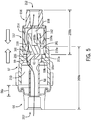
- Connector 350 may generally be configured to receive and retain lengths of tubing or otherwise form a hermetic seal to prevent fluid from leaving as sterile system.
- the connector 350 may comprise a generally hollow and cylindrical housing 409.
- the housing 409 may comprise a sub-housing 409a corresponding to one fluid pathway another sub-housing 409b corresponding to another fluid pathway.
- Sub-housings 409a and 409b may be configured to reversibly or irreversibly engage each other in sealing engagement.
- Each sub-housing 409a and 409b may also function as a connector per se, configured for engagement with any other connector having a complementary shape.
- Sub-housing 409a may comprise a socket segment 356 connected to a connector segment 357.
- the socket segment 356 may comprise an opening 407 configured to receive a fluid pathway, e.g. a length of tubing.
- the opening 207 may be in communication with a chamber 410 formed by the socket segment 356 and the connector segment 357.
- the connector segment 357 may comprise a small diameter portion 359 disposed between the chamber 410 and an opening 411 of the connector segment 357. Communication between the opening 407 of the socket portion 356 and the chamber 410 may be effected by a hollow channel 358 that extends from the opening 407 of the socket portion 356 through the chamber 410 past the small diameter portion 359 and is blocked at an end 361.
- the channel 358 may comprise at least one orifice 360 disposed within the chamber 410 that allows fluid communication between the opening 407 and the chamber 410.
- the end 361 of the channel 358 may cover the small diameter portion 359 such that the end 361 and the small diameter portion 359 form a hermetic seal separating the chamber 410 and the opening 411 when the first sub-housing is in a closed configuration.
- the diameter of the end 361 disposed on the chamber side of the small diameter portion 359 may be smaller than the diameter of the small diameter portion 359, while the diameter of the end 361 disposed on the side of the opening 411 may be larger than the diameter of the small diameter portion 359.
- the differences in diameters of the end 361 of the channel 358 may ensure that the end 361 does not retract back into the chamber 410.
- An open configuration of the first sub-housing 409a may be effected by rotation of the socket segment 356 and connector segment 357 relative to each other.
- the channel 358 may have outer threads 358a configured to mate with corresponding inner threads 357a of the connector portion 357 such that in the closed configuration of the sub-housing 409a, outer and inner threads 358a and 357a are tightly fastened, with the end 361 tightly sealed against the small diameter portion 359.
- Rotation of the socket segment 356 and connector segment 357 relative to each other may induce translational motion of the channel 358 and end 361 towards the opening 411 relative to the small diameter portion 359 of the connector portion 357.
- the translational motion may open the seal between the end 361 and the small diameter portion 359 due to the difference in diameters between the end 361 and the small diameter portion 359 to allow fluid flow between the chamber 410 and the opening 411.
- Sub-housing 409b may comprise a socket segment 456 connected to a connector segment 457.
- the socket segment 456 may comprise an opening 412 configured to receive a fluid pathway, e.g., a length of tubing.
- the opening 412 may be in communication with a chamber 414 formed by the socket segment 456 and the connector segment 457.
- the connector segment 457 may comprise a small diameter portion 459 disposed between the chamber 414 and an opening 415 of the connector segment 457. Communication between the opening 412 of the socket portion 456 and the chamber 414 may be effected by a hollow channel 362 that extends from the opening 412 of the socket portion 456 through the chamber 414 past the small diameter portion 459 and is blocked at an end 461.
- the channel 362 may comprise at least one orifice 460 disposed within the chamber 414 that allows fluid communication between the opening 412 and the chamber 414.
- the end 461 of the channel 362 may cover the small diameter portion 459 such that the end 461 and the small diameter portion 459 form a hermetic seal separating the chamber 414 and the opening 415 when the first sub-housing is in a closed configuration.
- the diameter of the end 461 disposed on the chamber side of the small diameter portion 459 may be smaller than the diameter of the small diameter portion 459, while the diameter of the end 461 disposed on the side of the opening 415 may be larger than the diameter of the small diameter portion 459.
- the differences in diameters of the end 461 of the channel 362 may ensure that the end 461 does not retract back into the chamber 414.
- An open configuration of the second sub-housing 409b may be effected by rotation of the socket segment 456 and connector segment 457 relative to each other.
- the channel 362 may have outer threads 458a configured to mate with corresponding inner threads 457a of the connector portion 457 such that in the closed configuration of the sub-housing 409b, outer and inner threads 458a and 457a are tightly fastened, with the end 461 tightly sealed against the small diameter portion 459.
- Rotation of the socket segment 456 and connector segment 457 relative to each other may induce translational motion of the channel 362 and end 461 towards the opening 415 relative to the small diameter portion 459 of the connector portion 457.
- the translational motion may open the seal between the end 461 and the small diameter portion 459 due to the difference in diameters between the end 461 and the small diameter portion 459 to allow fluid flow between the chamber 414 and the opening 415.
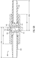
- FIG. 6B a longitudinal cross section view of the connector 350 is shown in which sub-housings 409a and 409b are engaged with each other in sealing engagement, according to an exemplary embodiment.
- Fig. 6B depicts both sub-housings 409a and 409b in closed configurations.
- the opening 411 of the connector segment 357 of the sub-housing 409a and the opening 415 of the connector segment 457 of the sub-housing 409b may be configured to form an enclosed chamber 416.
- the inner surface 411a of the connector portion 357 forming the opening 411, the end 361 of the channel 358, and/or the end 461 of the channel 362 may together form the walls of the enclosed chamber 416.
- the connector segments 357 and 457 may be configured such that the outer surface of one segment forms a friction fit, interference fit, Luer fit, threaded fit, etc., with the other segment.
- the outer surfaces 415b ( Fig. 6A ) of the connector segment 357 may be configured to hermetically engage with the inner surfaces 415a of the connector segment 457.
- the socket portion 356 of sub-housing 409a and the socket segment 456 of sub-housing 409b and any fluid contained therein may not require sterilization and may comprise biological materials sensitive to the sterilization energy. Therefore, it may be desirable for the socket portions 356 and 456 to comprise a material with low permeability to the sterilization energy and for the connector portions 357 and 457 to comprise a material with high permeability to the sterilization energy.
- the connector portions 357 and 457 may comprise a substantially UVC-transparent material, such as cyclic olefin copolymer (COC), poly(methyl methacrylate) (PMMA), polymethylpentene (PMP or TPX), and/or quartz glass, and the socket portions 356 and 456 may comprise a substantially UVC-opaque material, such as polycarbonate, PVC, and/or ABS.
- a substantially UVC-transparent material such as cyclic olefin copolymer (COC), poly(methyl methacrylate) (PMMA), polymethylpentene (PMP or TPX), and/or quartz glass
- the socket portions 356 and 456 may comprise a substantially UVC-opaque material, such as polycarbonate, PVC, and/or ABS.
- the connector portions 357 and 457 may comprise a heat conductive material, such as polycarbonate, PVC, and/or ABS, and the socket portions 356 and 456 may further comprise a substantially heat transmissive material and may even comprise heat resistive material, such as polyurethane and/or silica aerogel.
- connector portions 357 and 457 may be made of one material permeable to the sterilization energy for a segment 217 surrounding the sterilization chamber 416 and another material less permeable to the sterilization energy for the remaining portions of connector portions 357 and 457.
- fluid communication may be opened between chambers 410 and 416.
- Sub-housing 409a may be shifted to an open configuration by rotating the socket segment 356 and connector segment 357 relative to each other. Rotation may induce translational motion of the channel 358 and end 361 towards the opening 411 relative to the small diameter portion 359 of the connector portion 357. The translational motion may open the seal between the end 361 and the small diameter portion 359. Fluid from the sub-housing 409a may flow from within the channel 358 through the orifice 360 into the chamber 410 past the small diameter portion 359 and into the sterilization chamber 416.
- Sub-housing 409b may likewise be shifted to an open configuration by rotating the socket segment 456 and connector segment 457 relative to each other. Rotation may induce translational motion of the channel 362 and end 461 towards the opening 415 relative to the small diameter portion 459 of the connector portion 457. The translational motion may open the seal between the end 461 and the small diameter portion 459. Fluid from the sterilization chamber 416 may flow through the small diameter portion 359 into the chamber 414 and into the orifice 460 of the channel 362.
- the socket portions 356, 456 may incorporate O-rings 335 disposed between outer threads 358a, 458a and the chambers 410, 414 to prevent leakage of fluid from chambers 410, 414 into the space between the socket portions 356, 456 and the connector portions 357, 457.
- shifting the connector 350 into the open configuration via rotation of socket portions 356 and 456 relative to the connector portions 357 and 457 may be induced simultaneously by fixing the socket portions 356 and 456 in place and rotating the connector portion 457.
- the engagement (friction fit, interference fit, Luerfit, threaded fit, etc.) between the connector segments 357 and 457 may induce connector segment 357 to rotate along with segment 457.
- the outer surface 415c ( Fig.
- the connector portion 457 may comprise an outer diameter larger than the rest of the connector portion 457.
- the outer surface 415c may also comprise gears 415d, as shown in Fig. 8 , and may be rotated by a device having complementary gears.
- the device providing the sterilization energy source 300 may comprise a mold configured to receive the connector 350, engage the sub-housings 409a and 409b, apply the sterilization energy source, hold the socket portions 356 and 456 in place, and shift both sub-housings 409a and 409b into open configurations simultaneously by rotating the outer surface 415c while holding the socket portions 356 and 456 in place.
- a tube connector for a fluid circuit system comprising a housing.
- a first opening is configured to receive a first length of tubing in communication with a first chamber.
- a second opening is configured for communicating with the first chamber when the tube connector is in an open configuration but not in a closed configuration.
- a third opening is configured to receive a second length of tubing in communication with a second chamber.
- a fourth opening is configured for communicating with the second chamber when the tube connector is in the open configuration but not in the closed configuration. The second opening and the fourth opening are configured to engage each other to form a third chamber.
- the housing comprises a first sub-housing comprising the first opening, the second opening, and the first chamber.
- a second sub-housing comprises the third opening, the fourth opening, and the second chamber.
- At least a portion of the first and/or second sub-housings comprises a material comprising at least one of cyclic olefin copolymer (COC), poly(methyl methacrylate), polymethylpentene, and quartz glass.
- the first and second sub-housings each comprises a connector portion and a socket portion, and the tube connector is configured to shift from a closed configuration to an open configuration when the connector portions are rotated relative to the socket portions.
- the tube connector is configured to shift from a closed configuration to an open configuration when the second or fourth opening is translationally shifted relative to the first or third opening.
- the tube connector is configured to shift from a closed configuration to an open configuration when the first and/or second chamber is translationally shifted relative to the third chamber.
- the second opening and the fourth opening are configured to engage each other in at least one of a friction fit, an interference fit, a Luer fit, and a threaded fit to form the third chamber.
- the connector portion of the first or second sub-housings further comprises a geared outer surface, which rotation is configured to simultaneously rotate both connector portions relative to both socket portions when the socket portions are fixed in place.
- a method of sterilely connecting two fluid pathways comprising a first connector comprising a first chamber and a first open end and configured to connect to a first fluid pathway.
- the first chamber is configured to communicate with the first fluid pathway and the first open end when the first connector is in an open configuration but not in a closed configuration.
- a second connector comprising a second chamber and a second open end and configured to connect to a second fluid pathway.
- the second chamber is configured to communicate with the second fluid pathway and the second open end when the second connector is in an open configuration but not in a closed configuration.
- the first open end and the second open end are configured for engagement to form a third chamber.
- the third chamber is configured to communicate with the first chamber when the first connector is in the open configuration but not in the closed configuration and communicate with the second chamber when the second connector is in the open configuration but not in the closed configuration.
- the first open end and the second open end forming the third chamber comprises a first material at least partially permeable to a sterilization energy source for sterilizing contents of the third chamber.
- a first portion of the first connector surrounding the first chamber and a second portion of the second connector surrounding the second chamber comprise a second material less permeable to the sterilization energy source.
- the sterilization energy source comprises a UVC emitter and the first material comprises at least one of cyclic olefin copolymer, poly(methyl methacrylate), polymethylpentene, and quartz glass.
- the sterilization energy source comprises at least one of heat, steam, ebeam, and gamma rays and the second material comprises polyurethane and/or silica aerogel.
- the first and second connectors each comprises a connector portion and a socket portion.
- the first connector is configured to shift from the closed configuration to the open configuration when the connector portion of the first connector is rotated relative to the socket portion of the first connector.
- the second connector is configured to shift from the closed configuration to the open configuration when the connector portion of the second connector is rotated relative to the socket portion of the second connector.
- the first or second connector is configured to shift from the closed configuration to the open configuration when the first or second open end is translationally shifted relative to the first or second fluid pathway.
- the first or second connector is configured to shift from the closed configuration to the open configuration when the first or second chamber is translationally shifted relative to the third chamber; or when the first or second chamber is translationally shifted relative to the first or second fluid pathway.
- the first and second open ends are configured to engage each other in at least one of a friction fit, an interference fit, a Luer fit, and a threaded fit to form the third chamber.
- the first and second connectors each comprises a connector portion and a socket portion.
- the first or second chamber is translationally shifted relative to the third chamber or to the first or second fluid pathway by rotating the connector portion of the first connector relative to the socket portion of the first connector and by rotating the connector portion of the second connector relative to the socket portion of the second connector.
- a first opening is configured to receive a first length of tubing in communication with a first chamber.
- a second opening is configured for communicating with the first chamber when the tube connector is in an open configuration but not in a closed configuration.
- the second opening is configured to reversibly engage a third opening to form a second chamber.
- the third opening is configured for communicating with a second length of tubing.
- a first portion of the housing forming the first opening comprises a material at least partially permeable to a sterilization energy source for sterilizing contents of the second chamber.
- a second portion of the housing forming the first opening comprises a material less permeable to the sterilization energy source
- the material comprises at least one of cyclic olefin copolymer, poly(methyl methacrylate), polymethylpentene, and quartz glass, and the sterilization energy source comprises UVC.
- the material of the second portion comprises polyurethane and/or silica aerogel and the sterilization energy source comprises at least one of heat, steam, ebeam, and gamma rays.
- the housing further comprises a connector portion and a socket portion, and the tube connector is configured to shift from the closed configuration to the open configuration when the connector portion is rotated relative to the socket portion.
- the tube connector is configured to shift from the closed configuration to the open configuration when a linear force is applied to the tube connector in a direction parallel to the first length of tubing.
Landscapes
- Health & Medical Sciences (AREA)
- Heart & Thoracic Surgery (AREA)
- Life Sciences & Earth Sciences (AREA)
- Animal Behavior & Ethology (AREA)
- General Health & Medical Sciences (AREA)
- Public Health (AREA)
- Veterinary Medicine (AREA)
- Engineering & Computer Science (AREA)
- Hematology (AREA)
- Anesthesiology (AREA)
- Biomedical Technology (AREA)
- Epidemiology (AREA)
- Pulmonology (AREA)
- Vascular Medicine (AREA)
- Mechanical Engineering (AREA)
- Physics & Mathematics (AREA)
- Optics & Photonics (AREA)
- External Artificial Organs (AREA)
- Infusion, Injection, And Reservoir Apparatuses (AREA)
Applications Claiming Priority (1)
| Application Number | Priority Date | Filing Date | Title |
|---|---|---|---|
| US201762608995P | 2017-12-21 | 2017-12-21 |
Publications (3)
| Publication Number | Publication Date |
|---|---|
| EP3501594A2 true EP3501594A2 (fr) | 2019-06-26 |
| EP3501594A3 EP3501594A3 (fr) | 2019-07-31 |
| EP3501594B1 EP3501594B1 (fr) | 2026-04-15 |
Family
ID=64746366
Family Applications (1)
| Application Number | Title | Priority Date | Filing Date |
|---|---|---|---|
| EP18214466.7A Active EP3501594B1 (fr) | 2017-12-21 | 2018-12-20 | Système et procédé de connexion stérile des passages de fluide |
Country Status (2)
| Country | Link |
|---|---|
| US (1) | US11090478B2 (fr) |
| EP (1) | EP3501594B1 (fr) |
Cited By (1)
| Publication number | Priority date | Publication date | Assignee | Title |
|---|---|---|---|---|
| WO2024153916A3 (fr) * | 2023-01-16 | 2025-02-13 | Microfluidx Ltd | Systèmes et procédés de connexion aseptique |
Families Citing this family (8)
| Publication number | Priority date | Publication date | Assignee | Title |
|---|---|---|---|---|
| JP3234453U (ja) * | 2018-10-26 | 2021-10-14 | 新銀健康有限公司(新加坡)Singsilver Health Pte. Ltd. | 尿の逆流を防止する逆流ストッパー |
| GB201909315D0 (en) * | 2019-06-28 | 2019-08-14 | Ge Healthcare Bio Sciences Ab | Improvements in and relating to steriliasation of fluid-guiding elements |
| EP3888734A1 (fr) | 2020-04-02 | 2021-10-06 | Fenwal, Inc. | Système de connexion stérile réversible |
| US11007292B1 (en) | 2020-05-01 | 2021-05-18 | Uv Innovators, Llc | Automatic power compensation in ultraviolet (UV) light emission device, and related methods of use, particularly suited for decontamination |
| US20230285734A1 (en) * | 2022-03-14 | 2023-09-14 | Fenwal, Inc. | Reversible sterile connection system |
| DE102023205195A1 (de) | 2023-06-02 | 2024-12-05 | Fraunhofer-Gesellschaft zur Förderung der angewandten Forschung eingetragener Verein | Sterilkonnektor |
| US12188003B1 (en) | 2023-09-28 | 2025-01-07 | Trisk Bio Ltd. | Methods and systems for performing biochemical processes |
| US12013066B1 (en) * | 2023-11-03 | 2024-06-18 | Trisk Bio Ltd. | Methods and systems for reversibly consummating fluidic connections |
Citations (2)
| Publication number | Priority date | Publication date | Assignee | Title |
|---|---|---|---|---|
| US5194145A (en) | 1984-03-21 | 1993-03-16 | William F. McLaughlin | Method and apparatus for separation of matter from suspension |
| US5868696A (en) | 1993-12-22 | 1999-02-09 | Baxter International Inc. | Peristaltic pump tube holder with pump tube shield and cover |
Family Cites Families (5)
| Publication number | Priority date | Publication date | Assignee | Title |
|---|---|---|---|---|
| EP2683470B1 (fr) | 2011-03-11 | 2017-05-03 | Fenwal, Inc. | Dispositifs de séparation par membrane, systèmes et procédés les employant, systèmes et procédés de gestion de données |
| WO2013153722A1 (fr) * | 2012-04-13 | 2013-10-17 | テルモ株式会社 | Structure de connexion de tube |
| US10351271B2 (en) * | 2012-05-01 | 2019-07-16 | Dr. Py Institute Llc | Device for connecting or filling and method |
| BR112014027280A2 (pt) | 2012-05-01 | 2017-06-27 | Py Dr Inst Llc | dispositivo para conexão ou enchimento e método |
| US10525249B2 (en) * | 2016-03-07 | 2020-01-07 | Fenwal, Inc. | System and method for creating sterile connections using ultraviolet light |
-
2018
- 2018-12-20 EP EP18214466.7A patent/EP3501594B1/fr active Active
- 2018-12-20 US US16/227,714 patent/US11090478B2/en active Active
Patent Citations (2)
| Publication number | Priority date | Publication date | Assignee | Title |
|---|---|---|---|---|
| US5194145A (en) | 1984-03-21 | 1993-03-16 | William F. McLaughlin | Method and apparatus for separation of matter from suspension |
| US5868696A (en) | 1993-12-22 | 1999-02-09 | Baxter International Inc. | Peristaltic pump tube holder with pump tube shield and cover |
Cited By (1)
| Publication number | Priority date | Publication date | Assignee | Title |
|---|---|---|---|---|
| WO2024153916A3 (fr) * | 2023-01-16 | 2025-02-13 | Microfluidx Ltd | Systèmes et procédés de connexion aseptique |
Also Published As
| Publication number | Publication date |
|---|---|
| EP3501594B1 (fr) | 2026-04-15 |
| US20190192844A1 (en) | 2019-06-27 |
| EP3501594A3 (fr) | 2019-07-31 |
| US11090478B2 (en) | 2021-08-17 |
Similar Documents
| Publication | Publication Date | Title |
|---|---|---|
| EP3501594B1 (fr) | Système et procédé de connexion stérile des passages de fluide | |
| US20080132876A1 (en) | Connector System for Sterile Connection | |
| EP2678657B1 (fr) | Système d'échantillonnage aseptique | |
| RU2500103C2 (ru) | Контейнерная система для крови и кассета | |
| US20020185186A1 (en) | Fluid transfer devices and methods of use | |
| EP1387711A1 (fr) | Dispositifs de raccordement pour des fluides et leurs procedes d'utilisation | |
| CN104684596A (zh) | 利用重力分离供体血液的移动系统 | |
| WO2015149908A1 (fr) | Dispositif de transfert de fluide et procédé de transfert de fluide de manière aseptique | |
| CN105120912B (zh) | 血液袋系统 | |
| EP3088070B1 (fr) | Dispositif à module membranaire, corps de boîtier, et système de traitement de liquide | |
| KR20080039327A (ko) | 무균 전송 시스템을 구비한 수용 용기 | |
| EP2810668B1 (fr) | Dispositif de commutation de circulation sanguine et système de poche de sang | |
| WO2013136889A1 (fr) | Dispositif de raccordement de trajectoire d'écoulement du sang et système de poche de sang | |
| EP3842118B1 (fr) | Procédé et système de récupération de fluide | |
| EP2523644B1 (fr) | Dispositif de transfert de fluide | |
| EP3842116B1 (fr) | Procédé de récupération de fluide | |
| WO2020196347A1 (fr) | Récipient pour concentrer des cellules | |
| EP4665442A1 (fr) | Raccords union pour joindre des conduits de fluide | |
| EP3669984B1 (fr) | Cassettes de traitement de fluide incorporant des canaux micro et macrofluidiques | |
| JP7802426B2 (ja) | 液体採取容器、および液体成分取り出しシステム | |
| WO2023074303A1 (fr) | Récipient de collecte de liquide, procédé de production de récipient de collecte de liquide et système d'élimination de composant liquide | |
| EP3484574A1 (fr) | Raccord de ligne de fluide médical | |
| JP2013203659A (ja) | 血液処理フィルタ及び血液回路 | |
| WO2022186122A1 (fr) | Système de sacs de sang et méthode de traitement du sang | |
| KR20240045334A (ko) | 원심 분리된 물질의 깨끗한 전달을 위한 장치 및 방법 |
Legal Events
| Date | Code | Title | Description |
|---|---|---|---|
| PUAI | Public reference made under article 153(3) epc to a published international application that has entered the european phase |
Free format text: ORIGINAL CODE: 0009012 |
|
| STAA | Information on the status of an ep patent application or granted ep patent |
Free format text: STATUS: THE APPLICATION HAS BEEN PUBLISHED |
|
| AK | Designated contracting states |
Kind code of ref document: A2 Designated state(s): AL AT BE BG CH CY CZ DE DK EE ES FI FR GB GR HR HU IE IS IT LI LT LU LV MC MK MT NL NO PL PT RO RS SE SI SK SM TR |
|
| AX | Request for extension of the european patent |
Extension state: BA ME |
|
| PUAL | Search report despatched |
Free format text: ORIGINAL CODE: 0009013 |
|
| AK | Designated contracting states |
Kind code of ref document: A3 Designated state(s): AL AT BE BG CH CY CZ DE DK EE ES FI FR GB GR HR HU IE IS IT LI LT LU LV MC MK MT NL NO PL PT RO RS SE SI SK SM TR |
|
| AX | Request for extension of the european patent |
Extension state: BA ME |
|
| RIC1 | Information provided on ipc code assigned before grant |
Ipc: A61M 39/10 20060101ALI20190627BHEP Ipc: A61M 39/18 20060101AFI20190627BHEP Ipc: A61M 39/26 20060101ALI20190627BHEP Ipc: A61M 39/16 20060101ALN20190627BHEP |
|
| STAA | Information on the status of an ep patent application or granted ep patent |
Free format text: STATUS: REQUEST FOR EXAMINATION WAS MADE |
|
| 17P | Request for examination filed |
Effective date: 20200109 |
|
| RBV | Designated contracting states (corrected) |
Designated state(s): AL AT BE BG CH CY CZ DE DK EE ES FI FR GB GR HR HU IE IS IT LI LT LU LV MC MK MT NL NO PL PT RO RS SE SI SK SM TR |
|
| STAA | Information on the status of an ep patent application or granted ep patent |
Free format text: STATUS: EXAMINATION IS IN PROGRESS |
|
| 17Q | First examination report despatched |
Effective date: 20221116 |
|
| GRAP | Despatch of communication of intention to grant a patent |
Free format text: ORIGINAL CODE: EPIDOSNIGR1 |
|
| STAA | Information on the status of an ep patent application or granted ep patent |
Free format text: STATUS: GRANT OF PATENT IS INTENDED |
|
| RIC1 | Information provided on ipc code assigned before grant |
Ipc: A61M 39/18 20060101AFI20251015BHEP Ipc: A61M 39/10 20060101ALI20251015BHEP Ipc: A61M 39/26 20060101ALI20251015BHEP Ipc: A61M 39/16 20060101ALN20251015BHEP |
|
| RIC1 | Information provided on ipc code assigned before grant |
Ipc: A61M 39/18 20060101AFI20251021BHEP Ipc: A61M 39/10 20060101ALI20251021BHEP Ipc: A61M 39/26 20060101ALI20251021BHEP Ipc: A61M 39/16 20060101ALN20251021BHEP |
|
| INTG | Intention to grant announced |
Effective date: 20251031 |
|
| RIN1 | Information on inventor provided before grant (corrected) |
Inventor name: BRIERTON, MARK Inventor name: WEGENER, CHRISTOPHER J. |
|
| GRAJ | Information related to disapproval of communication of intention to grant by the applicant or resumption of examination proceedings by the epo deleted |
Free format text: ORIGINAL CODE: EPIDOSDIGR1 |
|
| STAA | Information on the status of an ep patent application or granted ep patent |
Free format text: STATUS: EXAMINATION IS IN PROGRESS |
|
| GRAP | Despatch of communication of intention to grant a patent |
Free format text: ORIGINAL CODE: EPIDOSNIGR1 |
|
| STAA | Information on the status of an ep patent application or granted ep patent |
Free format text: STATUS: GRANT OF PATENT IS INTENDED |
|
| INTC | Intention to grant announced (deleted) | ||
| GRAS | Grant fee paid |
Free format text: ORIGINAL CODE: EPIDOSNIGR3 |
|
| RIC1 | Information provided on ipc code assigned before grant |
Ipc: A61M 39/18 20060101AFI20260203BHEP Ipc: A61M 39/10 20060101ALI20260203BHEP Ipc: A61M 39/26 20060101ALI20260203BHEP Ipc: A61M 39/16 20060101ALN20260203BHEP |
|
| GRAA | (expected) grant |
Free format text: ORIGINAL CODE: 0009210 |
|
| STAA | Information on the status of an ep patent application or granted ep patent |
Free format text: STATUS: THE PATENT HAS BEEN GRANTED |
|
| INTG | Intention to grant announced |
Effective date: 20260211 |
|
| AK | Designated contracting states |
Kind code of ref document: B1 Designated state(s): AL AT BE BG CH CY CZ DE DK EE ES FI FR GB GR HR HU IE IS IT LI LT LU LV MC MK MT NL NO PL PT RO RS SE SI SK SM TR |
|
| REG | Reference to a national code |
Ref country code: CH Ref legal event code: F10 Free format text: ST27 STATUS EVENT CODE: U-0-0-F10-F00 (AS PROVIDED BY THE NATIONAL OFFICE) Effective date: 20260415 Ref country code: GB Ref legal event code: FG4D |
|
| REG | Reference to a national code |
Ref country code: DE Ref legal event code: R096 Ref document number: 602018090559 Country of ref document: DE |