EP3501859B1 - Sender - Google Patents
Sender Download PDFInfo
- Publication number
- EP3501859B1 EP3501859B1 EP17912352.6A EP17912352A EP3501859B1 EP 3501859 B1 EP3501859 B1 EP 3501859B1 EP 17912352 A EP17912352 A EP 17912352A EP 3501859 B1 EP3501859 B1 EP 3501859B1
- Authority
- EP
- European Patent Office
- Prior art keywords
- pressure
- tire
- terminal
- box
- deforming portion
- Prior art date
- Legal status (The legal status is an assumption and is not a legal conclusion. Google has not performed a legal analysis and makes no representation as to the accuracy of the status listed.)
- Not-in-force
Links
Images




Classifications
-
- B—PERFORMING OPERATIONS; TRANSPORTING
- B60—VEHICLES IN GENERAL
- B60C—VEHICLE TYRES; TYRE INFLATION; TYRE CHANGING; CONNECTING VALVES TO INFLATABLE ELASTIC BODIES IN GENERAL; DEVICES OR ARRANGEMENTS RELATED TO TYRES
- B60C23/00—Devices for measuring, signalling, controlling, or distributing tyre pressure or temperature, specially adapted for mounting on vehicles; Arrangement of tyre inflating devices on vehicles, e.g. of pumps or of tanks; Tyre cooling arrangements
- B60C23/02—Signalling devices actuated by tyre pressure
- B60C23/04—Signalling devices actuated by tyre pressure mounted on the wheel or tyre
- B60C23/0408—Signalling devices actuated by tyre pressure mounted on the wheel or tyre transmitting the signals by non-mechanical means from the wheel or tyre to a vehicle body mounted receiver
-
- G—PHYSICS
- G01—MEASURING; TESTING
- G01L—MEASURING FORCE, STRESS, TORQUE, WORK, MECHANICAL POWER, MECHANICAL EFFICIENCY, OR FLUID PRESSURE
- G01L13/00—Devices or apparatus for measuring differences of two or more fluid pressure values
- G01L13/02—Devices or apparatus for measuring differences of two or more fluid pressure values using elastically-deformable members or pistons as sensing elements
-
- G—PHYSICS
- G01—MEASURING; TESTING
- G01L—MEASURING FORCE, STRESS, TORQUE, WORK, MECHANICAL POWER, MECHANICAL EFFICIENCY, OR FLUID PRESSURE
- G01L15/00—Devices or apparatus for measuring two or more fluid pressure values simultaneously
-
- G—PHYSICS
- G01—MEASURING; TESTING
- G01L—MEASURING FORCE, STRESS, TORQUE, WORK, MECHANICAL POWER, MECHANICAL EFFICIENCY, OR FLUID PRESSURE
- G01L17/00—Devices or apparatus for measuring tyre pressure or the pressure in other inflated bodies
-
- G—PHYSICS
- G01—MEASURING; TESTING
- G01L—MEASURING FORCE, STRESS, TORQUE, WORK, MECHANICAL POWER, MECHANICAL EFFICIENCY, OR FLUID PRESSURE
- G01L19/00—Details of, or accessories for, apparatus for measuring steady or quasi-steady pressure of a fluent medium insofar as such details or accessories are not special to particular types of pressure gauges
- G01L19/0092—Pressure sensor associated with other sensors, e.g. for measuring acceleration or temperature
Definitions
- the present invention enables the warning device to issue a warning immediately after a sudden pressure change in the tire.
- the pressure switch 40 includes a box 41 made of metal.
- the box 41 is hollow and includes a cylindrical peripheral wall 42, a wall section 44, and a deforming portion 45.
- the wall section 44 is arranged on one of the opposite ends (the opposite axial ends) of the peripheral wall 42.
- the deforming portion 45 is arranged on the other one of the opposite ends of the peripheral wall 42.
- the wall section 44 has a circular and flat plate-like shape.
- the pressure difference between the interior and the exterior of the box 41 necessary for elastically deforming the deforming portion 45 changes depending on the shape of the deforming portion 45, the material of the deforming portion 45, the dimensions of the deforming portion 45, the cross-sectional flow area of the passages 48, and the volume of the box 41.
- the deforming portion 45 is provided such that "predetermined value" is satisfied. This enables elastic deformation of the deforming portion 45 when the pressure in the box 41 is higher than the pressure in the tire 14 at least by the amount corresponding to the predetermined value.
- the elastic force of the deforming portion 45 restores the original shape of the deforming portion 45.
- the deforming portion 45 and the terminal 36 thus separate from each other, thus ending electric power supply to the transmission circuit 34. That is, when a sudden pressure change occurs in the tire 14, the transmission circuit 34 is temporarily supplied with electric power.
- the pressure switch 40 is turned on and off depending on the pressure difference. In this manner, the pressure switch 40 functions as a mechanical switch that switches between supplying electric power to the transmission circuit 34 and blocking such supply of the electric power.
- the reception circuit 63 receives the data signals, the pressure drop signals, and the warning signals that are transmitted by the transmitters 20 through the reception antenna 64.
- the reception circuit 63 demodulates the data signals, the pressure drop signals, and the warning signals and outputs the signals to the reception controller 62.
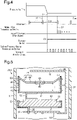
- the controller 24 obtains the pressure data at a point in time T0 and then at a point in time T2 in the subsequent cycle.
- the point in time T1 is between the point in time T0 and the point in time T2.
- the deforming portion 45 of the pressure switch 40 comes into contact with the terminal 36. This causes the transmission circuit 34 to transmit the warning signal. Since the time necessary for elastic deformation of the deforming portion 45 is short, the warning signal is transmitted immediately after the sudden pressure change. In other words, the warning signal is transmitted sooner than the pressure drop signal.
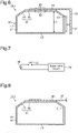
- a pressure switch that has the box 41 of the present embodiment but without the passages 48 may be used as a pressure switch 200.
- the deforming portion 45 of the pressure switch 200 projects on the outer side of the peripheral wall 42 and is thus in contact with the terminal 36.
- the pressure switch 200 is arranged in the tire 14, the pressure in the exterior of the box 41 is higher than the pressure in the box 41.
- the deforming portion 45 thus separates from the terminal 36.
- the deforming portion 45 of the pressure switch 200 is deformed by the pressure (the absolute pressure) in the exterior of the box 41.
- a sudden-pressure-change transmission device using the pressure switch 200 is first manufactured.
- the deforming portion 45 and the terminal 36 are in contact with each other until the sudden-pressure-change transmission device is mounted in the wheel assembly 12. Therefore, the warning signal is continuously transmitted until the sudden-pressure-change transmission device is mounted in the wheel assembly 12, thus increasing consumption of the electric power of the battery 30.
- Contact between the deforming portion 45 and the terminal 36 may be prevented by maintaining an insulating material between the deforming portion 45 and the terminal 36 until the sudden-pressure-change transmission device is mounted in the wheel assembly 12.
- attachment and detachment of the insulating material is troublesome.
- locking may be performed to suspend transmission of the warning signal until the sudden-pressure-change transmission device is attached to the wheel assembly 12. Such locking is canceled after the sudden-pressure-change transmission device is mounted in the wheel assembly 12.
- a trigger device or the like must be used to selectively cause and cancel such locking, which is also troublesome.
- the sudden-pressure-change transmission device 20B of the present embodiment elastically deforms the deforming portion 45 in response to the pressure difference between the interior and the exterior of the box 41. Therefore, contact between the deforming portion 45 and the terminal 36 is considered unlikely in the period from when the sudden-pressure-change transmission device 20B is manufactured to when the sudden-pressure-change transmission device 20B is mounted in the wheel assembly 12. Even if the deforming portion 45 is elastically deformed and comes into contact with the terminal 36 before the sudden-pressure-change transmission device 20B is mounted in the wheel assembly 12, the deforming portion 45 elastically restores its original shape. This restrains continuous transmission of the warning signal for a prolonged period.
- warning is enabled not only when the tire 14 has a problem caused by a sudden pressure change but also when the pressure in the tire 14 slowly drops to an excessively low level.
- the above-described embodiment has the sudden-pressure-change transmission device 20B dedicated to transmit the warning signal at the time of a sudden pressure change.
- the normal-time transmission device 20A may have a function of transmitting the warning signal.
- the transmitter 20 thus lacks the sudden-pressure-change transmission device 20B and includes only the normal-time transmission device 20A.
- the controller 24 and the normal-time transmission circuit 25 of the normal-time transmission device 20A serve as a transmitting section.
- the transmitting section is a component necessary for transmitting the warning signal. If, as described above regarding the above-described embodiment, transmission of the warning signal is accomplished only by the transmission circuit 34, the transmission circuit 34 serves as the transmitting section. If, as shown in Fig. 10 , the data generated by the controller 24 is transmitted from the normal-time transmission circuit 25, the controller 24 and the normal-time transmission circuit 25 serve as the transmitting section.
- a terminal 81 of a transmitting section 82 is an interrupt terminal.
- the deforming portion 45 comes into contact with the terminal 81 when the pressure in the box 41 becomes higher than the pressure in the tire 14 at least by the amount corresponding to the predetermined value.
- Such contact between the deforming portion 45 and the terminal 81 changes the voltage level, thus causing the controller 24 to perform an interrupt procedure.
- the interrupt procedure may be a procedure of transmitting a warning signal from the normal-time transmission device 20A.
- the interrupt procedure may be a procedure of obtaining the pressure data from the pressure sensor 21. After the pressure data is obtained from the pressure sensor 21, the transmitting section 82 transmits a pressure drop signal as the warning signal. In either case, when a sudden pressure change occurs, the tire pressure warning device 60 is caused to issue a warning in response to contact between the deforming portion 45 and the terminal 81.
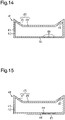
- the pressure switch 40 may include an accommodated body 70 accommodated in the box 41.
- the accommodated body 70 functions as a flow rate limiting portion and includes a contacting portion 71 and a side wall 72.
- the contacting portion 71 comes into contact with the contact portion 46.
- the side wall 72 extends from the contacting portion 71 to the wall section 44.
- the accommodated body 70 includes a communication passage 73 and a through-hole 74.
- the communication passage 73 extends through the contacting portion 71.
- the through-hole 74 extends through the side wall 72.
- the communication passage 73 has a cross-sectional flow area smaller than that of a passage 75 arranged in the contact portion 46.
- the terminal 36 has a terminal passage 76 facing the passage 75.
- the cross-sectional flow area of the terminal passage 76 is greater than the cross-sectional flow area of the communication passage 73.
- Elastic deformation of the deforming portion 45 causes communication between the passage 75 and the terminal passage 76.
- the gas discharged through the communication passage 73 is discharged through the passage 75. If the deforming portion 45 and the contacting portion 71 are in contact with each other, the flow rate of the gas discharged from the box 41 through the passage 75 depends on the cross-sectional flow area of the communication passage 73.
- the passage 75 and the terminal passage 76 communicate with each other.
- the flow rate of the gas discharged through the passage 75 depends on the cross-sectional flow area of the terminal passage 76.
- the cross-sectional flow area of the terminal passage 76 is greater than the cross-sectional flow area of the communication passage 73.
- the flow rate of the gas discharged through the passage 75 is thus smaller when the deforming portion 45 and the terminal 36 are separate from each other than when the deforming portion 45 and the terminal 36 are in contact with each other.
- the accommodated body 70 and the terminal passage 76 function as a flow rate increasing portion.
- a sudden pressure drop causes contact between the deforming portion 45 and the terminal 36.
- Such contact between the deforming portion 45 and the terminal 36 causes the flow rate of discharged gas to be smaller than that when the deforming portion 45 is in contact with the contacting portion 71.
- Such shape restoration of the deforming portion 45 causes contact between the deforming portion 45 and the contacting portion 71, thus reducing the flow rate of the gas discharged from the box 41.
- This promotes increase of the difference between the pressure in the tire 14 and the pressure in the box 41, thus elastically re-deforming the deforming portion 45.
- the deforming portion 45 repeatedly comes into contact with and separates from the terminal 36 in an alternating manner.
- the deforming portion 45 elastically deforms and comes into contact with the tubular portion 84.
- the passages 48 communicate with the range surrounded by the tubular portion 84 and the contact portion 46.
- the range and the interior of the tire 14 communicate with each other through the terminal passage 85. Since the cross-sectional flow area of the terminal passage 85 is smaller than the cross-sectional flow area of each passage 48, the flow rate of the gas discharged through the passages 48 is small when the deforming portion 45 and the contact portion 46 are in contact with each other.
- the tubular portion 84 and the terminal passage 85 function as a flow rate reducing portion.
- the terminal 36 may have a terminal passage 91.
- the terminal passage 91 When the deforming portion 45 and the terminal 36 come into contact with each other, the terminal passage 91 becomes overlapped with a section of a passage 90 arranged in the contact portion 46.
- the terminal passage 91 has a cross-sectional flow area not less than the cross-sectional flow area of the passage 90.
- the area by which the terminal passage 91 and the passage 90 are overlapped with each other when the deforming portion 45 is in contact with the terminal 36 is less than the cross-sectional flow area of the passage 90. Therefore, the terminal passage 91 functions as a flow rate reducing portion to reduce the flow rate of the gas discharged through the passage 90 when the deforming portion 45 and the contact portion 46 are in contact with each other.
- the terminal 36 may include a terminal passage 93.
- the terminal passage 93 communicates with some of the passages 48 arranged in the contact portion 46.
- the terminal passage 93 functions as a flow rate reducing portion to reduce the flow rate of the gas discharged through the passages 48 when the deforming portion 45 and the contact portion 46 are in contact with each other.
- a passage 96 of the pressure switch 40 may have an air-permeable filter 97. Since the filter 97 causes pressure loss, the air permeability of the filter 97 is taken into consideration when setting the cross-sectional flow area of the passage 96.
- the deforming portion does not necessarily have to be made of metal as long as the deforming portion is conductive and elastically deformable.
- the deforming portion may be made of elastically deformable conductive plastic or made of an elastically deformable plastic material having a metal-plated or conductive-coated surface or an elastically deformable plastic material having a metal mesh attached thereto.
- the deforming portion does not necessarily have to be conductive as a whole, if it is conductive at least in the section that contacts the terminal 36.
- the listed deforming portions are light-weighted and enable shape setting with improved flexibility. Further, these deforming portions are easier to machine than a deforming portion made of metal.
- the passages 48 may be replaced by a single passage 48.
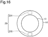
- the normal-time transmission device 20A and the sudden-pressure-change transmission device 20B do not necessarily have to be integrated with each other but may be attached to the wheel assembly 12 independently from each other as shown in Fig. 16 .
- the normal-time transmission device 20A and the sudden-pressure-change transmission device 20B may each be attached to the wheel assembly 12 by being integrated with the tire valve 16 or being bonded to the inner side of the wheel 13 or the inner side of the tire 14. That is, the normal-time transmission device 20A and the sudden-pressure-change transmission device 20B may be attached at any site as long as the transmission devices 20A, 20B are arranged in the tire 14 and capable of detecting the pressure in the tire 14. Specifically, by attaching the normal-time transmission device 20A and the sudden-pressure-change transmission device 20B at opposite positions with respect to the rotation axis of the wheel 13, a light-weighted balance weight can be employed for balance adjustment of the tire 14.
- the tire pressure warning device may be any device as long as the device has a function of receiving a warning signal and a function of issuing a warning, such as a portable terminal carried by an occupant of the vehicle.
- the vehicle may be a motorcycle or a vehicle having five or more wheel assemblies.
- Signals of the 2.4 GHz band may be used as the data signal, the pressure drop signal, and the warning signal.
- the transmitter 20 may transmit the data signal at a constant position (for example, the lowermost position). Based on the correlative relationship between the timing at which the reception controller 62 receives the data signal from the transmitter 20 and the rotation angle of the wheel assembly 12 at the time of reception of the data signal, the reception controller 62 may determine which of the wheel assemblies 12 the transmitter 20 is mounted in (auto-location). Specifically, the rotation angle of the wheel assembly 12 is obtained from an anti-lock braking system (ABS). In this case, by employing a common ID code for each normal-time transmission device 20A and the associated sudden-pressure-change transmission device 20B, the receiver 61 can determine which of the wheel assemblies 12 the sudden-pressure-change transmission device 20B that has transmitted the data signal is mounted in.
- ABS anti-lock braking system
- the receiver 61 can determine which of the tires 14 of the wheel assemblies 12 has a problem. Specifically, even if each normal-time transmission device 20A and the associated sudden-pressure-change transmission device 20B employ different ID codes, the same effect as the above-described effect is obtained by memorizing the ID codes as associated with each other in the reception-side memory section 62b.
- the box 41 or the terminal 35, 36 may be used as an antenna of the transmission circuit 34.
Landscapes
- Physics & Mathematics (AREA)
- General Physics & Mathematics (AREA)
- Engineering & Computer Science (AREA)
- Mechanical Engineering (AREA)
- Chemical & Material Sciences (AREA)
- Analytical Chemistry (AREA)
- Measuring Fluid Pressure (AREA)
- Tires In General (AREA)
Claims (4)
- Sender (20), der dazu ausgelegt ist, in einem Reifen (14) angeordnet zu sein, um zu bewirken, dass eine Reifendruckwarnvorrichtung (60) eine Warnung ausgibt, wobei der Sender (20) Folgendes umfasst:einen Sendeabschnitt (34), der einen Anschluss (36) aufweist; undeinen Druckschalter (40), wobeider Druckschalter (40) einen hohlen Kasten (41) und einen Durchgang (48) umfasst, der bewirkt, dass ein Inneres des Kastens (41) und ein Inneres des Reifens (14) miteinander in Verbindung stehen,der Kasten (41) einen leitenden Verformungsabschnitt (45) umfasst, der dazu ausgestaltet ist, von dem Anschluss (36) des Sendeabschnitts getrennt zu sein, wenn eine Differenz zwischen einem Druck in dem Kasten (41) und einem Druck in dem Reifen (14) kleiner als ein vorbestimmter Wert ist, und elastisch verformt zu werden, um mit dem Anschluss (36) in Kontakt zu kommen, wenn der Druck in dem Kasten (41) mindestens um den vorbestimmten Wert höher als der Druck in dem Reifen (14) ist, undder Sendeabschnitt (34) dazu ausgestaltet ist, in Reaktion auf einen Kontakt zwischen dem Verformungsabschnitt (45) und dem Anschluss (36) ein Warnsignal zu senden, das bewirkt, dass die Reifendruckwarnvorrichtung (60) eine Warnung ausgibt,dadurch gekennzeichnet, dass der Sender (20) ferner einen Durchflussratenverringerungsabschnitt (36) umfasst, der dazu ausgestaltet ist, in einem Zustand, in dem der Druck in dem Reifen (14) kleiner als der Druck in dem Kasten (41) ist, zu bewirken, dass eine Durchflussrate von aus dem Kasten (41) abgegebenem Gas durch den Durchgang (48) kleiner ist, wenn der Verformungsabschnitt (45) und der Anschluss (36) in Kontakt miteinander sind, als wenn der Verformungsabschnitt (45) und der Anschluss (36) voneinander getrennt sind.
- Sender (20) nach Anspruch 1, wobei der Durchgang (48) in dem Verformungsabschnitt (45) bereitgestellt ist und der Anschluss (36) dazu ausgestaltet ist, die Durchflussrate des aus dem Kasten (41) abgegebenen Gases durch den Durchgang (48) zu begrenzen, wenn der Anschluss (36) mit dem Verformungsabschnitt (45) in Kontakt ist.
- Sender (20), der dazu ausgelegt ist, in einem Reifen (14) angeordnet zu sein, um zu bewirken, dass eine Reifendruckwarnvorrichtung (60) eine Warnung ausgibt, wobei der Sender (20) Folgendes umfasst:einen Sendeabschnitt (34), der einen Anschluss (36) aufweist; undeinen Druckschalter (40), wobeider Druckschalter (40) einen hohlen Kasten (41) und einen Durchgang (48) umfasst, der bewirkt, dass ein Inneres des Kastens (41) und ein Inneres des Reifens (14) miteinander in Verbindung stehen,der Kasten (41) einen leitenden Verformungsabschnitt (45) umfasst, der dazu ausgestaltet ist, von dem Anschluss (36) des Sendeabschnitts getrennt zu sein, wenn eine Differenz zwischen einem Druck in dem Kasten (41) und einem Druck in dem Reifen (14) kleiner als ein vorbestimmter Wert ist, und elastisch verformt zu werden, um mit dem Anschluss (36) in Kontakt zu kommen, wenn der Druck in dem Kasten (41) mindestens um den vorbestimmten Wert höher als der Druck in dem Reifen (14) ist, undder Sendeabschnitt (34) dazu ausgestaltet ist, in Reaktion auf einen Kontakt zwischen dem Verformungsabschnitt (45) und dem Anschluss (36) ein Warnsignal zu senden, das bewirkt, dass die Reifendruckwarnvorrichtung (60) eine Warnung ausgibt,dadurch gekennzeichnet, dass der Sender (20) ferner einen Durchflussratenerhöhungsabschnitt (70, 76) umfasst, der dazu ausgestaltet ist, in einem Zustand, in dem der Druck in dem Reifen (14) kleiner als der Druck in dem Kasten (41) ist, zu bewirken, dass eine Durchflussrate von aus dem Kasten (41) abgegebenem Gas durch den Durchgang (48) kleiner ist, wenn der Verformungsabschnitt (45) und der Anschluss (36) voneinander getrennt sind, als wenn der Verformungsabschnitt (45) und der Anschluss (36) miteinander in Kontakt sind.
- Sender (20) nach Anspruch 3, wobeider Durchgang (48) in dem Verformungsabschnitt (45) bereitgestellt ist, undder Durchflussratenerhöhungsabschnitt (70, 76) einen in dem Kasten (41) angeordneten Durchflussratenbegrenzungsabschnitt (70) umfasst, undder Durchflussratenbegrenzungsabschnitt (70) dazu ausgestaltet ist, die Durchflussrate des aus dem Kasten (41) abgegebenen Gases durch den Durchgang (48) zu begrenzen, wenn der Verformungsabschnitt (45) und der Anschluss (36) voneinander getrennt sind.
Applications Claiming Priority (1)
| Application Number | Priority Date | Filing Date | Title |
|---|---|---|---|
| PCT/JP2017/038777 WO2019082353A1 (ja) | 2017-10-26 | 2017-10-26 | 送信機 |
Publications (3)
| Publication Number | Publication Date |
|---|---|
| EP3501859A1 EP3501859A1 (de) | 2019-06-26 |
| EP3501859A4 EP3501859A4 (de) | 2020-02-12 |
| EP3501859B1 true EP3501859B1 (de) | 2022-05-18 |
Family
ID=66246319
Family Applications (1)
| Application Number | Title | Priority Date | Filing Date |
|---|---|---|---|
| EP17912352.6A Not-in-force EP3501859B1 (de) | 2017-10-26 | 2017-10-26 | Sender |
Country Status (5)
| Country | Link |
|---|---|
| US (1) | US11794531B2 (de) |
| EP (1) | EP3501859B1 (de) |
| JP (1) | JP6817332B2 (de) |
| CN (1) | CN109963729B (de) |
| WO (1) | WO2019082353A1 (de) |
Families Citing this family (1)
| Publication number | Priority date | Publication date | Assignee | Title |
|---|---|---|---|---|
| JP7356570B2 (ja) * | 2020-03-03 | 2023-10-04 | アルプスアルパイン株式会社 | タイヤマウントセンサ |
Family Cites Families (15)
| Publication number | Priority date | Publication date | Assignee | Title |
|---|---|---|---|---|
| JPS5722027U (de) * | 1980-07-15 | 1982-02-04 | ||
| FR2614240B1 (fr) * | 1987-04-23 | 1989-07-28 | Jaeger | Dispositif de controle et d'alarme pour pneumatiques de vehicule. |
| JP2505125Y2 (ja) | 1990-11-30 | 1996-07-24 | 太平洋工業株式会社 | タイヤ空気圧警報装置の圧力検出器 |
| JPH0886712A (ja) * | 1993-07-29 | 1996-04-02 | Bridgestone Corp | タイヤ用空気圧センサ及びその製造方法 |
| JPH11348516A (ja) * | 1998-06-05 | 1999-12-21 | Pacific Ind Co Ltd | タイヤ空気圧警報装置 |
| JP2000118214A (ja) * | 1998-10-09 | 2000-04-25 | Kyowa Electron Instr Co Ltd | タイヤ内圧監視装置 |
| JP2004330887A (ja) | 2003-05-08 | 2004-11-25 | Honda Motor Co Ltd | 圧力スイッチ及び圧力スイッチを用いたタイヤ空気圧監視装置 |
| US7348878B2 (en) * | 2005-09-29 | 2008-03-25 | International Truck Intellectual Property Company, Llc | Tire pressure monitoring system with permanent tire identification |
| WO2008133314A1 (ja) * | 2007-04-24 | 2008-11-06 | Bridgestone Corporation | センサモジュール |
| JP2009173148A (ja) * | 2008-01-24 | 2009-08-06 | Topy Ind Ltd | タイヤ監視システム及び監視方法 |
| EP2423007B1 (de) * | 2009-04-24 | 2016-09-07 | Toyota Jidosha Kabushiki Kaisha | Vorrichtung zur reifenluftdrucküberwachung |
| CN201890097U (zh) * | 2010-11-09 | 2011-07-06 | 翔鑫科技股份有限公司 | 胎压侦测装置 |
| CN103317978A (zh) * | 2012-03-21 | 2013-09-25 | 李尔汽车电子电器(上海)有限公司 | 轮胎压力监测装置 |
| JP2014091344A (ja) | 2012-10-31 | 2014-05-19 | Yokohama Rubber Co Ltd:The | タイヤ状態監視システムおよび監視装置 |
| CN106507669B (zh) * | 2015-06-26 | 2018-08-28 | 太平洋工业株式会社 | 车轮位置确定装置 |
-
2017
- 2017-10-26 WO PCT/JP2017/038777 patent/WO2019082353A1/ja not_active Ceased
- 2017-10-26 JP JP2018557153A patent/JP6817332B2/ja not_active Expired - Fee Related
- 2017-10-26 EP EP17912352.6A patent/EP3501859B1/de not_active Not-in-force
- 2017-10-26 CN CN201780029362.5A patent/CN109963729B/zh not_active Expired - Fee Related
- 2017-10-26 US US16/306,642 patent/US11794531B2/en active Active
Also Published As
| Publication number | Publication date |
|---|---|
| EP3501859A4 (de) | 2020-02-12 |
| US20210268848A1 (en) | 2021-09-02 |
| WO2019082353A1 (ja) | 2019-05-02 |
| JP6817332B2 (ja) | 2021-01-20 |
| CN109963729A (zh) | 2019-07-02 |
| US11794531B2 (en) | 2023-10-24 |
| JPWO2019082353A1 (ja) | 2020-09-10 |
| CN109963729B (zh) | 2021-01-26 |
| EP3501859A1 (de) | 2019-06-26 |
Similar Documents
| Publication | Publication Date | Title |
|---|---|---|
| US20070080795A1 (en) | Tire sensor device and tire information transmission method | |
| US6549125B2 (en) | Tire condition sensor unit mounting arrangement | |
| US20110309927A1 (en) | Intelligent tire systems and methods | |
| US11198336B2 (en) | Transmission and receiving arrangement for a tire pressure detection device | |
| JP2003182328A (ja) | タイヤ状態監視装置の送信機及びタイヤ状態監視装置 | |
| US8217776B2 (en) | Tire pressure sensor location identification | |
| CN102612441B (zh) | 发送轮胎状态相关信息的发送装置以及轮胎状态监测系统 | |
| EP3165384B1 (de) | Vorrichtung zur erfassung des reifenzustands | |
| EP3501859B1 (de) | Sender | |
| EP3162596B1 (de) | Vorrichtung zur drehpositionsidentifizierung einer radanordnung | |
| AU2013275529B2 (en) | Condition detection device | |
| CN115943089B (zh) | 与车载无线传感器设备相关联的持续警报发送 | |
| US7336164B2 (en) | Tire pressure monitoring system and sensor therefor | |
| EP1268226B1 (de) | Montageanordnung für reifenzustandssensor | |
| US20070063829A1 (en) | Battery-less tire pressure monitoring system | |
| EP1792757B1 (de) | Reifenzustandsüberwachungssystem | |
| US20090224903A1 (en) | Tire air pressure monitoring system | |
| US6935169B2 (en) | Tire pressure sensor array | |
| JP4787546B2 (ja) | タイヤ管理システム | |
| JP2004090772A (ja) | 車輪状態監視システム | |
| JP4367292B2 (ja) | 制御調整機構および制御装置 | |
| CN121650377A (zh) | 用于检测轮胎压力的装置、用于接收该装置的轮胎内胎或轮辋以及具有该装置的轮胎内胎或轮辋 | |
| JP6131198B2 (ja) | タイヤ状態監視装置 | |
| JP2008300228A (ja) | 圧力検出装置及びその装置を用いたタイヤ空気圧検出システム | |
| JP2022153692A (ja) | 締結センサ及び締結管理システム |
Legal Events
| Date | Code | Title | Description |
|---|---|---|---|
| STAA | Information on the status of an ep patent application or granted ep patent |
Free format text: STATUS: UNKNOWN |
|
| STAA | Information on the status of an ep patent application or granted ep patent |
Free format text: STATUS: THE INTERNATIONAL PUBLICATION HAS BEEN MADE |
|
| PUAI | Public reference made under article 153(3) epc to a published international application that has entered the european phase |
Free format text: ORIGINAL CODE: 0009012 |
|
| STAA | Information on the status of an ep patent application or granted ep patent |
Free format text: STATUS: REQUEST FOR EXAMINATION WAS MADE |
|
| 17P | Request for examination filed |
Effective date: 20181212 |
|
| AK | Designated contracting states |
Kind code of ref document: A1 Designated state(s): AL AT BE BG CH CY CZ DE DK EE ES FI FR GB GR HR HU IE IS IT LI LT LU LV MC MK MT NL NO PL PT RO RS SE SI SK SM TR |
|
| AX | Request for extension of the european patent |
Extension state: BA ME |
|
| A4 | Supplementary search report drawn up and despatched |
Effective date: 20200113 |
|
| RIC1 | Information provided on ipc code assigned before grant |
Ipc: B60C 23/02 20060101AFI20200107BHEP Ipc: B60C 23/04 20060101ALI20200107BHEP |
|
| DAV | Request for validation of the european patent (deleted) | ||
| DAX | Request for extension of the european patent (deleted) | ||
| GRAP | Despatch of communication of intention to grant a patent |
Free format text: ORIGINAL CODE: EPIDOSNIGR1 |
|
| STAA | Information on the status of an ep patent application or granted ep patent |
Free format text: STATUS: GRANT OF PATENT IS INTENDED |
|
| INTG | Intention to grant announced |
Effective date: 20211213 |
|
| GRAS | Grant fee paid |
Free format text: ORIGINAL CODE: EPIDOSNIGR3 |
|
| GRAA | (expected) grant |
Free format text: ORIGINAL CODE: 0009210 |
|
| STAA | Information on the status of an ep patent application or granted ep patent |
Free format text: STATUS: THE PATENT HAS BEEN GRANTED |
|
| AK | Designated contracting states |
Kind code of ref document: B1 Designated state(s): AL AT BE BG CH CY CZ DE DK EE ES FI FR GB GR HR HU IE IS IT LI LT LU LV MC MK MT NL NO PL PT RO RS SE SI SK SM TR |
|
| REG | Reference to a national code |
Ref country code: GB Ref legal event code: FG4D |
|
| REG | Reference to a national code |
Ref country code: CH Ref legal event code: EP |
|
| REG | Reference to a national code |
Ref country code: IE Ref legal event code: FG4D |
|
| REG | Reference to a national code |
Ref country code: DE Ref legal event code: R096 Ref document number: 602017057755 Country of ref document: DE |
|
| REG | Reference to a national code |
Ref country code: AT Ref legal event code: REF Ref document number: 1492964 Country of ref document: AT Kind code of ref document: T Effective date: 20220615 |
|
| REG | Reference to a national code |
Ref country code: LT Ref legal event code: MG9D |
|
| REG | Reference to a national code |
Ref country code: NL Ref legal event code: MP Effective date: 20220518 |
|
| REG | Reference to a national code |
Ref country code: AT Ref legal event code: MK05 Ref document number: 1492964 Country of ref document: AT Kind code of ref document: T Effective date: 20220518 |
|
| PG25 | Lapsed in a contracting state [announced via postgrant information from national office to epo] |
Ref country code: SE Free format text: LAPSE BECAUSE OF FAILURE TO SUBMIT A TRANSLATION OF THE DESCRIPTION OR TO PAY THE FEE WITHIN THE PRESCRIBED TIME-LIMIT Effective date: 20220518 Ref country code: PT Free format text: LAPSE BECAUSE OF FAILURE TO SUBMIT A TRANSLATION OF THE DESCRIPTION OR TO PAY THE FEE WITHIN THE PRESCRIBED TIME-LIMIT Effective date: 20220919 Ref country code: NO Free format text: LAPSE BECAUSE OF FAILURE TO SUBMIT A TRANSLATION OF THE DESCRIPTION OR TO PAY THE FEE WITHIN THE PRESCRIBED TIME-LIMIT Effective date: 20220818 Ref country code: NL Free format text: LAPSE BECAUSE OF FAILURE TO SUBMIT A TRANSLATION OF THE DESCRIPTION OR TO PAY THE FEE WITHIN THE PRESCRIBED TIME-LIMIT Effective date: 20220518 Ref country code: LT Free format text: LAPSE BECAUSE OF FAILURE TO SUBMIT A TRANSLATION OF THE DESCRIPTION OR TO PAY THE FEE WITHIN THE PRESCRIBED TIME-LIMIT Effective date: 20220518 Ref country code: HR Free format text: LAPSE BECAUSE OF FAILURE TO SUBMIT A TRANSLATION OF THE DESCRIPTION OR TO PAY THE FEE WITHIN THE PRESCRIBED TIME-LIMIT Effective date: 20220518 Ref country code: GR Free format text: LAPSE BECAUSE OF FAILURE TO SUBMIT A TRANSLATION OF THE DESCRIPTION OR TO PAY THE FEE WITHIN THE PRESCRIBED TIME-LIMIT Effective date: 20220819 Ref country code: FI Free format text: LAPSE BECAUSE OF FAILURE TO SUBMIT A TRANSLATION OF THE DESCRIPTION OR TO PAY THE FEE WITHIN THE PRESCRIBED TIME-LIMIT Effective date: 20220518 Ref country code: ES Free format text: LAPSE BECAUSE OF FAILURE TO SUBMIT A TRANSLATION OF THE DESCRIPTION OR TO PAY THE FEE WITHIN THE PRESCRIBED TIME-LIMIT Effective date: 20220518 Ref country code: BG Free format text: LAPSE BECAUSE OF FAILURE TO SUBMIT A TRANSLATION OF THE DESCRIPTION OR TO PAY THE FEE WITHIN THE PRESCRIBED TIME-LIMIT Effective date: 20220818 Ref country code: AT Free format text: LAPSE BECAUSE OF FAILURE TO SUBMIT A TRANSLATION OF THE DESCRIPTION OR TO PAY THE FEE WITHIN THE PRESCRIBED TIME-LIMIT Effective date: 20220518 |
|
| PG25 | Lapsed in a contracting state [announced via postgrant information from national office to epo] |
Ref country code: RS Free format text: LAPSE BECAUSE OF FAILURE TO SUBMIT A TRANSLATION OF THE DESCRIPTION OR TO PAY THE FEE WITHIN THE PRESCRIBED TIME-LIMIT Effective date: 20220518 Ref country code: PL Free format text: LAPSE BECAUSE OF FAILURE TO SUBMIT A TRANSLATION OF THE DESCRIPTION OR TO PAY THE FEE WITHIN THE PRESCRIBED TIME-LIMIT Effective date: 20220518 Ref country code: LV Free format text: LAPSE BECAUSE OF FAILURE TO SUBMIT A TRANSLATION OF THE DESCRIPTION OR TO PAY THE FEE WITHIN THE PRESCRIBED TIME-LIMIT Effective date: 20220518 Ref country code: IS Free format text: LAPSE BECAUSE OF FAILURE TO SUBMIT A TRANSLATION OF THE DESCRIPTION OR TO PAY THE FEE WITHIN THE PRESCRIBED TIME-LIMIT Effective date: 20220918 |
|
| PG25 | Lapsed in a contracting state [announced via postgrant information from national office to epo] |
Ref country code: SM Free format text: LAPSE BECAUSE OF FAILURE TO SUBMIT A TRANSLATION OF THE DESCRIPTION OR TO PAY THE FEE WITHIN THE PRESCRIBED TIME-LIMIT Effective date: 20220518 Ref country code: SK Free format text: LAPSE BECAUSE OF FAILURE TO SUBMIT A TRANSLATION OF THE DESCRIPTION OR TO PAY THE FEE WITHIN THE PRESCRIBED TIME-LIMIT Effective date: 20220518 Ref country code: RO Free format text: LAPSE BECAUSE OF FAILURE TO SUBMIT A TRANSLATION OF THE DESCRIPTION OR TO PAY THE FEE WITHIN THE PRESCRIBED TIME-LIMIT Effective date: 20220518 Ref country code: EE Free format text: LAPSE BECAUSE OF FAILURE TO SUBMIT A TRANSLATION OF THE DESCRIPTION OR TO PAY THE FEE WITHIN THE PRESCRIBED TIME-LIMIT Effective date: 20220518 Ref country code: DK Free format text: LAPSE BECAUSE OF FAILURE TO SUBMIT A TRANSLATION OF THE DESCRIPTION OR TO PAY THE FEE WITHIN THE PRESCRIBED TIME-LIMIT Effective date: 20220518 Ref country code: CZ Free format text: LAPSE BECAUSE OF FAILURE TO SUBMIT A TRANSLATION OF THE DESCRIPTION OR TO PAY THE FEE WITHIN THE PRESCRIBED TIME-LIMIT Effective date: 20220518 |
|
| REG | Reference to a national code |
Ref country code: DE Ref legal event code: R097 Ref document number: 602017057755 Country of ref document: DE |
|
| PLBE | No opposition filed within time limit |
Free format text: ORIGINAL CODE: 0009261 |
|
| STAA | Information on the status of an ep patent application or granted ep patent |
Free format text: STATUS: NO OPPOSITION FILED WITHIN TIME LIMIT |
|
| PG25 | Lapsed in a contracting state [announced via postgrant information from national office to epo] |
Ref country code: AL Free format text: LAPSE BECAUSE OF FAILURE TO SUBMIT A TRANSLATION OF THE DESCRIPTION OR TO PAY THE FEE WITHIN THE PRESCRIBED TIME-LIMIT Effective date: 20220518 |
|
| 26N | No opposition filed |
Effective date: 20230221 |
|
| PG25 | Lapsed in a contracting state [announced via postgrant information from national office to epo] |
Ref country code: SI Free format text: LAPSE BECAUSE OF FAILURE TO SUBMIT A TRANSLATION OF THE DESCRIPTION OR TO PAY THE FEE WITHIN THE PRESCRIBED TIME-LIMIT Effective date: 20220518 Ref country code: MC Free format text: LAPSE BECAUSE OF FAILURE TO SUBMIT A TRANSLATION OF THE DESCRIPTION OR TO PAY THE FEE WITHIN THE PRESCRIBED TIME-LIMIT Effective date: 20220518 |
|
| REG | Reference to a national code |
Ref country code: CH Ref legal event code: PL |
|
| REG | Reference to a national code |
Ref country code: BE Ref legal event code: MM Effective date: 20221031 |
|
| PG25 | Lapsed in a contracting state [announced via postgrant information from national office to epo] |
Ref country code: LU Free format text: LAPSE BECAUSE OF NON-PAYMENT OF DUE FEES Effective date: 20221026 |
|
| PG25 | Lapsed in a contracting state [announced via postgrant information from national office to epo] |
Ref country code: LI Free format text: LAPSE BECAUSE OF NON-PAYMENT OF DUE FEES Effective date: 20221031 Ref country code: CH Free format text: LAPSE BECAUSE OF NON-PAYMENT OF DUE FEES Effective date: 20221031 |
|
| PG25 | Lapsed in a contracting state [announced via postgrant information from national office to epo] |
Ref country code: BE Free format text: LAPSE BECAUSE OF NON-PAYMENT OF DUE FEES Effective date: 20221031 |
|
| PG25 | Lapsed in a contracting state [announced via postgrant information from national office to epo] |
Ref country code: IE Free format text: LAPSE BECAUSE OF NON-PAYMENT OF DUE FEES Effective date: 20221026 |
|
| PGFP | Annual fee paid to national office [announced via postgrant information from national office to epo] |
Ref country code: GB Payment date: 20230907 Year of fee payment: 7 |
|
| PGFP | Annual fee paid to national office [announced via postgrant information from national office to epo] |
Ref country code: FR Payment date: 20230911 Year of fee payment: 7 |
|
| PG25 | Lapsed in a contracting state [announced via postgrant information from national office to epo] |
Ref country code: IT Free format text: LAPSE BECAUSE OF FAILURE TO SUBMIT A TRANSLATION OF THE DESCRIPTION OR TO PAY THE FEE WITHIN THE PRESCRIBED TIME-LIMIT Effective date: 20220518 |
|
| PGFP | Annual fee paid to national office [announced via postgrant information from national office to epo] |
Ref country code: DE Payment date: 20230830 Year of fee payment: 7 |
|
| PG25 | Lapsed in a contracting state [announced via postgrant information from national office to epo] |
Ref country code: HU Free format text: LAPSE BECAUSE OF FAILURE TO SUBMIT A TRANSLATION OF THE DESCRIPTION OR TO PAY THE FEE WITHIN THE PRESCRIBED TIME-LIMIT; INVALID AB INITIO Effective date: 20171026 |
|
| PG25 | Lapsed in a contracting state [announced via postgrant information from national office to epo] |
Ref country code: CY Free format text: LAPSE BECAUSE OF FAILURE TO SUBMIT A TRANSLATION OF THE DESCRIPTION OR TO PAY THE FEE WITHIN THE PRESCRIBED TIME-LIMIT Effective date: 20220511 |
|
| PG25 | Lapsed in a contracting state [announced via postgrant information from national office to epo] |
Ref country code: MK Free format text: LAPSE BECAUSE OF FAILURE TO SUBMIT A TRANSLATION OF THE DESCRIPTION OR TO PAY THE FEE WITHIN THE PRESCRIBED TIME-LIMIT Effective date: 20220511 |
|
| PG25 | Lapsed in a contracting state [announced via postgrant information from national office to epo] |
Ref country code: MT Free format text: LAPSE BECAUSE OF FAILURE TO SUBMIT A TRANSLATION OF THE DESCRIPTION OR TO PAY THE FEE WITHIN THE PRESCRIBED TIME-LIMIT Effective date: 20220511 |
|
| PG25 | Lapsed in a contracting state [announced via postgrant information from national office to epo] |
Ref country code: BG Free format text: LAPSE BECAUSE OF FAILURE TO SUBMIT A TRANSLATION OF THE DESCRIPTION OR TO PAY THE FEE WITHIN THE PRESCRIBED TIME-LIMIT Effective date: 20220518 |
|
| PG25 | Lapsed in a contracting state [announced via postgrant information from national office to epo] |
Ref country code: BG Free format text: LAPSE BECAUSE OF FAILURE TO SUBMIT A TRANSLATION OF THE DESCRIPTION OR TO PAY THE FEE WITHIN THE PRESCRIBED TIME-LIMIT Effective date: 20220518 |
|
| REG | Reference to a national code |
Ref country code: DE Ref legal event code: R119 Ref document number: 602017057755 Country of ref document: DE |
|
| GBPC | Gb: european patent ceased through non-payment of renewal fee |
Effective date: 20241026 |
|
| PG25 | Lapsed in a contracting state [announced via postgrant information from national office to epo] |
Ref country code: DE Free format text: LAPSE BECAUSE OF NON-PAYMENT OF DUE FEES Effective date: 20250501 |
|
| PG25 | Lapsed in a contracting state [announced via postgrant information from national office to epo] |
Ref country code: GB Free format text: LAPSE BECAUSE OF NON-PAYMENT OF DUE FEES Effective date: 20241026 |
|
| PG25 | Lapsed in a contracting state [announced via postgrant information from national office to epo] |
Ref country code: FR Free format text: LAPSE BECAUSE OF NON-PAYMENT OF DUE FEES Effective date: 20241031 |
|
| PG25 | Lapsed in a contracting state [announced via postgrant information from national office to epo] |
Ref country code: TR Free format text: LAPSE BECAUSE OF FAILURE TO SUBMIT A TRANSLATION OF THE DESCRIPTION OR TO PAY THE FEE WITHIN THE PRESCRIBED TIME-LIMIT Effective date: 20220518 |