EP3501871A1 - Unité d'engrenage différentiel - Google Patents
Unité d'engrenage différentiel Download PDFInfo
- Publication number
- EP3501871A1 EP3501871A1 EP18206885.8A EP18206885A EP3501871A1 EP 3501871 A1 EP3501871 A1 EP 3501871A1 EP 18206885 A EP18206885 A EP 18206885A EP 3501871 A1 EP3501871 A1 EP 3501871A1
- Authority
- EP
- European Patent Office
- Prior art keywords
- hydraulic pump
- hydraulic
- rotatable
- cam ring
- rotation axis
- Prior art date
- Legal status (The legal status is an assumption and is not a legal conclusion. Google has not performed a legal analysis and makes no representation as to the accuracy of the status listed.)
- Granted
Links
Images


Classifications
-
- F—MECHANICAL ENGINEERING; LIGHTING; HEATING; WEAPONS; BLASTING
- F16—ENGINEERING ELEMENTS AND UNITS; GENERAL MEASURES FOR PRODUCING AND MAINTAINING EFFECTIVE FUNCTIONING OF MACHINES OR INSTALLATIONS; THERMAL INSULATION IN GENERAL
- F16H—GEARING
- F16H48/00—Differential gearings
- F16H48/20—Arrangements for suppressing or influencing the differential action, e.g. locking devices
- F16H48/27—Arrangements for suppressing or influencing the differential action, e.g. locking devices using internally-actuatable fluid pressure, e.g. internal pump types
-
- B—PERFORMING OPERATIONS; TRANSPORTING
- B60—VEHICLES IN GENERAL
- B60K—ARRANGEMENT OR MOUNTING OF PROPULSION UNITS OR OF TRANSMISSIONS IN VEHICLES; ARRANGEMENT OR MOUNTING OF PLURAL DIVERSE PRIME-MOVERS IN VEHICLES; AUXILIARY DRIVES FOR VEHICLES; INSTRUMENTATION OR DASHBOARDS FOR VEHICLES; ARRANGEMENTS IN CONNECTION WITH COOLING, AIR INTAKE, GAS EXHAUST OR FUEL SUPPLY OF PROPULSION UNITS IN VEHICLES
- B60K17/00—Arrangement or mounting of transmissions in vehicles
- B60K17/04—Arrangement or mounting of transmissions in vehicles characterised by arrangement, location or kind of gearing
- B60K17/16—Arrangement or mounting of transmissions in vehicles characterised by arrangement, location or kind of gearing of differential gearing
- B60K17/165—Arrangement or mounting of transmissions in vehicles characterised by arrangement, location or kind of gearing of differential gearing provided between independent half axles
-
- B—PERFORMING OPERATIONS; TRANSPORTING
- B60—VEHICLES IN GENERAL
- B60K—ARRANGEMENT OR MOUNTING OF PROPULSION UNITS OR OF TRANSMISSIONS IN VEHICLES; ARRANGEMENT OR MOUNTING OF PLURAL DIVERSE PRIME-MOVERS IN VEHICLES; AUXILIARY DRIVES FOR VEHICLES; INSTRUMENTATION OR DASHBOARDS FOR VEHICLES; ARRANGEMENTS IN CONNECTION WITH COOLING, AIR INTAKE, GAS EXHAUST OR FUEL SUPPLY OF PROPULSION UNITS IN VEHICLES
- B60K23/00—Arrangement or mounting of control devices for vehicle transmissions, or parts thereof, not otherwise provided for
- B60K23/04—Arrangement or mounting of control devices for vehicle transmissions, or parts thereof, not otherwise provided for for differential gearing
- B60K2023/046—Axle differential locking means
-
- B—PERFORMING OPERATIONS; TRANSPORTING
- B60—VEHICLES IN GENERAL
- B60Y—INDEXING SCHEME RELATING TO ASPECTS CROSS-CUTTING VEHICLE TECHNOLOGY
- B60Y2400/00—Special features of vehicle units
- B60Y2400/70—Gearings
- B60Y2400/78—Pumps, e.g. jet type
- B60Y2400/785—Pump drives
Definitions
- the invention relates to a differential gear unit for two-axle motor vehicles, having a first output shaft for transmitting torque to a first vehicle axle and a second output shaft for transmitting torque to a second vehicle axle, with a switched between the two output shafts differential.
- the object of the invention is to provide a differential unit of the type mentioned, which requires a smaller space with a reduced number of components.
- the differential gear is dependent on a difference in rotational speed between the two output shafts a drivable hydraulic pump, the hydraulic oil promotes a volume flow according to the speed difference and with a hydraulic control circuit with a hydraulic line connecting the pressure connection of the hydraulic pump with produces the suction connection of the hydraulic pump.
- the volume flow is controlled by the control unit so that the rotational speeds of the drive shafts match each other or to a preset speed difference.
- the hydraulic pump is preferably a piston pump, by the higher pressures and thus higher forces can be generated.
- a valve unit may be arranged, through which the volume flow of the hydraulic fluid flowing through the hydraulic line can be regulated in accordance with the speed difference.
- valve unit for rapid and precise control is preferably a solenoid valve unit that can be controlled by a control unit.
- the hydraulic pump may have a rotatable about a rotation axis rotor and a rotatable about the rotation cam ring, wherein the rotor is fixedly connected to the axis of rotation coaxial with the first vehicle axis and wherein the cam ring with the coaxial with the axis of rotation second vehicle axle and fixed a driven wheel of the motor drive is rotatably driven.
- the hydraulic pump may also have a rotor rotatable about an axis of rotation and a cam ring rotatable about the axis of rotation, wherein the rotor is fixedly connected to the second vehicle axis coaxial with the axis of rotation and wherein the cam ring is coaxial with the first axis coaxial with the axis of rotation Vehicle axle firmly connected and is rotatably driven by a driven gear of the motor drive.
- a further advantageous embodiment consists in that a first hydraulic pump has a first rotor rotatable about a rotation axis and a first control cam ring rotatable about the rotation axis and a second hydraulic pump has a second rotor rotatable about the rotation axis and a second control cam ring rotatable about the rotation axis, wherein the first cam ring and the second cam ring are rotatably driven together by a driven gear of the motor drive, wherein the pressure ports of the first hydraulic pump and the second hydraulic pump are connected to each other via a first hydraulic line, in which a controllable by a control unit first valve unit is arranged, which controls the volume flow in the first hydraulic line controls and wherein the suction ports of the first hydraulic pump and the second hydraulic pump are connected to each other via a second hydraulic line.
- a first hydraulic pump may also comprise a first rotor rotatable about a rotation axis and a first control cam ring rotatable about the rotation axis and a second hydraulic pump having a second rotor rotatable about the rotation axis and a second control cam ring rotatable about the rotation axis; the first rotor and the second rotor are rotatably driven together by a driven gear of the motor drive, wherein the pressure ports of the first hydraulic pump and the second hydraulic pump via a first hydraulic line are connected to each other, in which a controllable by a control unit first valve unit is arranged, the volume flow in the first hydraulic line controls and wherein the suction ports of the first hydraulic pump and the second hydraulic pump are connected to each other via a second hydraulic line.
- the first valve unit is preferably a 2/2 solenoid proportional valve.
- a further advantageous embodiment consists in that a first hydraulic pump has a first rotor rotatable about a rotation axis and a first control cam ring rotatable about the rotation axis and a second hydraulic pump has a second rotor rotatable about the rotation axis and a second control cam ring rotatable about the rotation axis a differential cage of a differential compensation and the first cam ring and the second cam ring are rotatably driven together by a driven gear of the motor drive, wherein the second vehicle axle are rotatably driven by a first axle of the differential compensation and the second vehicle axle from a second axle of the differential compensation, and wherein the Pressure connections of the first hydraulic pump and the second hydraulic pump via a first hydraulic line are connected to each other, in which a controllable by a control unit second valve unit is arranged, the controls the volume flow in the first hydraulic line and wherein the suction ports of the first hydraulic pump and the second hydraulic pump are connected to each other via a second hydraulic line, in which the control
- the second valve unit is a 2/4 solenoid proportional valve.
- the differential gear units of a motor vehicle shown in the figures have a driven wheel 1, which can be driven rotatably by a motor drive, not shown, of the motor vehicle.
- a cam ring 2 or a rotor 3 of a piston pump 5 is rotatably driven about a rotation axis 4.
- the rotor 3 or the cam ring 2 Coaxially to the axis of rotation 4, the rotor 3 or the cam ring 2 diametrically extending to each other a first output shaft 6 for drive transmission to a not shown first vehicle axle and a second output shaft 7 for drive transmission to a second vehicle axle, not shown.
- the volume flow of the piston pump 5 is controlled by a multi-way solenoid valve depending on a speed difference between the rotational speeds of the two output shafts 6 and 7.
- This speed difference can relate directly to the rotational speeds of the two output shafts 6 and 7, when the two vehicle axles are driven at the same speeds.
- the speed difference refers to the deviation from a preset speed difference of the rotational speeds.
- the multi-way solenoid valve and thus the volume flow is controlled by a control unit, not shown, so that the rotational speeds equal to each other or to the default speed difference.
- FIG. 1 In the embodiment of the FIG. 1 is driven by the output gear 1 of the cam ring 2 of the piston pump 5 rotatably about the rotation axis 4.
- the piston pump 5 delivers from its pressure port 8 hydraulic oil via a hydraulic line 9 to its suction port 10.
- a 2/2 solenoid valve 11 In the hydraulic line 9, a 2/2 solenoid valve 11 is arranged, which opens the valve passage in its one position and closes in the other position.
- the rotor 3 of the piston pump 5 is rotatably connected coaxially to the axis of rotation 4 with the first drive shaft 6, while the cam ring 2 of the piston pump 5 with the diametrically to the first output shaft 6 extending second output shaft 7 is rotatably connected.
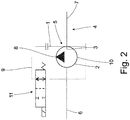
- FIG. 2 corresponds largely to the embodiment of FIG. 1 ,
- the rotor 3 of the piston pump 5 about the rotation axis 4, which is coaxial with the rotation axis 4 rotatably connected to the second drive shaft 7, during the Cam ring 2 of the piston pump 5 with the diametrically to the second output shaft 7 extending first output shaft 6 is rotatably connected.
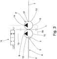
- the first piston pump 5 conveys from its pressure port 8 via a first hydraulic line 13 to the pressure port 14 of the second piston pump 5 '.
- the suction ports 10 and 15 of the first piston pump 5 'and the second piston pump are connected to each other via a second hydraulic line 16.
- a 2/2 solenoid valve 11 is arranged, which opens in its one position the valve passage and closes in the other position.
- the rotor 3 of the first piston pump 5 is rotatably connected coaxially to the rotation axis 4 with the first output shaft 6, while the rotor 17 of the second piston pump 5 'with the diametrically to the first output shaft 6 extending second output shaft 7 is rotatably connected.
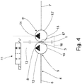
- FIG. 4 corresponds largely to the embodiment of FIG. 3 ,
- the first cam ring 12 of the first piston pump 5 and the second cam ring 12 'of the second piston pump 5' are rotatably driven about the rotation axis 4 coaxial with the rotation axis 4 with the first output shaft 6 and the second drive shaft 7 are rotatably connected ,
- FIG. 5 is driven by the driven gear 1, a first cam ring 12 of a first piston pump 5, a second cam ring 12 'of a second piston pump 5' and a differential carrier 18 of a between the two piston pumps 5 and 5 'arranged differential compensation 19 rotatably driven about the rotation axis 4.
- a to the axis of rotation 4 coaxial with a first Achswellenrad 23 connected first output shaft 20 of the differential compensation 19 is rotatably connected to the first output shaft 6.
- a to the axis of rotation 4 coaxial with a second axle 24 connected second output shaft 21 of the differential compensation 19 is rotatably connected to the second output shaft 7.
Landscapes
- Engineering & Computer Science (AREA)
- Mechanical Engineering (AREA)
- General Engineering & Computer Science (AREA)
- Chemical & Material Sciences (AREA)
- Combustion & Propulsion (AREA)
- Transportation (AREA)
- Physics & Mathematics (AREA)
- Fluid Mechanics (AREA)
- Retarders (AREA)
Applications Claiming Priority (2)
| Application Number | Priority Date | Filing Date | Title |
|---|---|---|---|
| DE102017223138 | 2017-12-19 | ||
| DE102018202028.0A DE102018202028A1 (de) | 2017-12-19 | 2018-02-09 | Ausgleichsgetriebeeinheit |
Publications (2)
| Publication Number | Publication Date |
|---|---|
| EP3501871A1 true EP3501871A1 (fr) | 2019-06-26 |
| EP3501871B1 EP3501871B1 (fr) | 2021-09-01 |
Family
ID=64362361
Family Applications (1)
| Application Number | Title | Priority Date | Filing Date |
|---|---|---|---|
| EP18206885.8A Active EP3501871B1 (fr) | 2017-12-19 | 2018-11-19 | Unité d'engrenage différentiel |
Country Status (1)
| Country | Link |
|---|---|
| EP (1) | EP3501871B1 (fr) |
Citations (5)
| Publication number | Priority date | Publication date | Assignee | Title |
|---|---|---|---|---|
| US2583307A (en) * | 1950-06-17 | 1952-01-22 | Albert P Schneider | Hydraulic control system |
| EP0267419A2 (fr) * | 1986-11-08 | 1988-05-18 | Robert Bosch Gmbh | Dispositif de verrouillage pour transmission différentielle |
| DE4330581A1 (de) * | 1992-09-09 | 1994-03-10 | Colombo Sige Brevetti | Differentialsperrsystem für eine Lenkantriebsachse |
| WO2005012768A1 (fr) * | 2003-07-24 | 2005-02-10 | Gkn Driveline International Gmbh | Transmission differentielle presentant un mecanisme de repartition variable du couple entre les arbres de sortie |
| DE102006018661A1 (de) * | 2006-04-21 | 2007-10-25 | Audi Ag | Differenzialgetriebe für ein Kraftfahrzeug |
-
2018
- 2018-11-19 EP EP18206885.8A patent/EP3501871B1/fr active Active
Patent Citations (5)
| Publication number | Priority date | Publication date | Assignee | Title |
|---|---|---|---|---|
| US2583307A (en) * | 1950-06-17 | 1952-01-22 | Albert P Schneider | Hydraulic control system |
| EP0267419A2 (fr) * | 1986-11-08 | 1988-05-18 | Robert Bosch Gmbh | Dispositif de verrouillage pour transmission différentielle |
| DE4330581A1 (de) * | 1992-09-09 | 1994-03-10 | Colombo Sige Brevetti | Differentialsperrsystem für eine Lenkantriebsachse |
| WO2005012768A1 (fr) * | 2003-07-24 | 2005-02-10 | Gkn Driveline International Gmbh | Transmission differentielle presentant un mecanisme de repartition variable du couple entre les arbres de sortie |
| DE102006018661A1 (de) * | 2006-04-21 | 2007-10-25 | Audi Ag | Differenzialgetriebe für ein Kraftfahrzeug |
Also Published As
| Publication number | Publication date |
|---|---|
| EP3501871B1 (fr) | 2021-09-01 |
Similar Documents
| Publication | Publication Date | Title |
|---|---|---|
| DE1755387C3 (de) | Hydrostatische Lenkeinrichtung, insbesondere fur schwere Fahrzeuge | |
| EP3954926B1 (fr) | Procédé de réalisation d'une interface de couple et de vitesse de rotation à performances limitées pour transmissions hydrostatiques | |
| DE3440219A1 (de) | Hydrostatische maschine | |
| DE102009011247A1 (de) | Hydrostatischer Antrieb | |
| DE3214688A1 (de) | Fluegelradpumpe | |
| EP2670639A1 (fr) | Pompe à denture intérieure double | |
| WO2019185263A1 (fr) | Système de prise de force | |
| DE2701302C2 (de) | Automotive Steuerung für einen hydrostatischen Fahrantrieb | |
| WO2008148512A1 (fr) | Dispositif de transmission de couple | |
| DE102014222322B3 (de) | Flügelzellenpumpe mit verbessertem Startverhalten | |
| EP3501871A1 (fr) | Unité d'engrenage différentiel | |
| WO2017045799A1 (fr) | Pompe volumétrique, procédé de fonctionnement d'une pompe volumétrique, système de direction et transmission | |
| DE10228800A1 (de) | Differenzialvorrichtung | |
| DE102018202028A1 (de) | Ausgleichsgetriebeeinheit | |
| DE3607709A1 (de) | Hydrostatische lenkanlage, insbesondere fuer kraftfahrzeuge | |
| DE102017209481B4 (de) | Fluidtechnische Ventileinrichtung sowie Verfahren zum Betreiben einer fluidtechnischen Ventileinrichtung | |
| DE19939474C2 (de) | Hydrostatischer Fahrantrieb mit Antischlupfregelung | |
| AT390305B (de) | Hydraulische steuereinheit | |
| EP3245425B1 (fr) | Convertisseur de couple hydraulique | |
| DE933973C (de) | Hydraulische Steuerung fuer die Kupplung in der Kraftuebertragung eines Kraftfahrzeuges | |
| DE2163456A1 (de) | Elektro-hydraulischer Schrittmotor | |
| DE3413683C2 (fr) | ||
| DE102015107519A1 (de) | Verdrängerpumpe, Verfahren zum Betreiben einer Verdrängerpumpe, Lenksystem und Getriebe | |
| DE102015005343A1 (de) | Pumpenanordnung für ein Kraftfahrzeug | |
| AT395748B (de) | Hydrodynamische kupplung |
Legal Events
| Date | Code | Title | Description |
|---|---|---|---|
| PUAI | Public reference made under article 153(3) epc to a published international application that has entered the european phase |
Free format text: ORIGINAL CODE: 0009012 |
|
| STAA | Information on the status of an ep patent application or granted ep patent |
Free format text: STATUS: THE APPLICATION HAS BEEN PUBLISHED |
|
| AK | Designated contracting states |
Kind code of ref document: A1 Designated state(s): AL AT BE BG CH CY CZ DE DK EE ES FI FR GB GR HR HU IE IS IT LI LT LU LV MC MK MT NL NO PL PT RO RS SE SI SK SM TR |
|
| AX | Request for extension of the european patent |
Extension state: BA ME |
|
| STAA | Information on the status of an ep patent application or granted ep patent |
Free format text: STATUS: REQUEST FOR EXAMINATION WAS MADE |
|
| 17P | Request for examination filed |
Effective date: 20191212 |
|
| STAA | Information on the status of an ep patent application or granted ep patent |
Free format text: STATUS: EXAMINATION IS IN PROGRESS |
|
| 17Q | First examination report despatched |
Effective date: 20200508 |
|
| REG | Reference to a national code |
Ref country code: DE Ref legal event code: R079 Ref document number: 502018006811 Country of ref document: DE Free format text: PREVIOUS MAIN CLASS: B60K0017160000 Ipc: B60K0023040000 |
|
| RIC1 | Information provided on ipc code assigned before grant |
Ipc: B60K 17/16 20060101ALI20210305BHEP Ipc: F16H 48/27 20120101ALI20210305BHEP Ipc: B60K 23/04 20060101AFI20210305BHEP |
|
| GRAP | Despatch of communication of intention to grant a patent |
Free format text: ORIGINAL CODE: EPIDOSNIGR1 |
|
| STAA | Information on the status of an ep patent application or granted ep patent |
Free format text: STATUS: GRANT OF PATENT IS INTENDED |
|
| INTG | Intention to grant announced |
Effective date: 20210420 |
|
| GRAS | Grant fee paid |
Free format text: ORIGINAL CODE: EPIDOSNIGR3 |
|
| GRAA | (expected) grant |
Free format text: ORIGINAL CODE: 0009210 |
|
| STAA | Information on the status of an ep patent application or granted ep patent |
Free format text: STATUS: THE PATENT HAS BEEN GRANTED |
|
| AK | Designated contracting states |
Kind code of ref document: B1 Designated state(s): AL AT BE BG CH CY CZ DE DK EE ES FI FR GB GR HR HU IE IS IT LI LT LU LV MC MK MT NL NO PL PT RO RS SE SI SK SM TR |
|
| REG | Reference to a national code |
Ref country code: GB Ref legal event code: FG4D Free format text: NOT ENGLISH |
|
| REG | Reference to a national code |
Ref country code: CH Ref legal event code: EP Ref country code: AT Ref legal event code: REF Ref document number: 1425874 Country of ref document: AT Kind code of ref document: T Effective date: 20210915 |
|
| REG | Reference to a national code |
Ref country code: DE Ref legal event code: R096 Ref document number: 502018006811 Country of ref document: DE |
|
| REG | Reference to a national code |
Ref country code: IE Ref legal event code: FG4D Free format text: LANGUAGE OF EP DOCUMENT: GERMAN |
|
| REG | Reference to a national code |
Ref country code: LT Ref legal event code: MG9D |
|
| REG | Reference to a national code |
Ref country code: NL Ref legal event code: MP Effective date: 20210901 |
|
| PG25 | Lapsed in a contracting state [announced via postgrant information from national office to epo] |
Ref country code: FI Free format text: LAPSE BECAUSE OF FAILURE TO SUBMIT A TRANSLATION OF THE DESCRIPTION OR TO PAY THE FEE WITHIN THE PRESCRIBED TIME-LIMIT Effective date: 20210901 Ref country code: ES Free format text: LAPSE BECAUSE OF FAILURE TO SUBMIT A TRANSLATION OF THE DESCRIPTION OR TO PAY THE FEE WITHIN THE PRESCRIBED TIME-LIMIT Effective date: 20210901 Ref country code: HR Free format text: LAPSE BECAUSE OF FAILURE TO SUBMIT A TRANSLATION OF THE DESCRIPTION OR TO PAY THE FEE WITHIN THE PRESCRIBED TIME-LIMIT Effective date: 20210901 Ref country code: SE Free format text: LAPSE BECAUSE OF FAILURE TO SUBMIT A TRANSLATION OF THE DESCRIPTION OR TO PAY THE FEE WITHIN THE PRESCRIBED TIME-LIMIT Effective date: 20210901 Ref country code: RS Free format text: LAPSE BECAUSE OF FAILURE TO SUBMIT A TRANSLATION OF THE DESCRIPTION OR TO PAY THE FEE WITHIN THE PRESCRIBED TIME-LIMIT Effective date: 20210901 Ref country code: NO Free format text: LAPSE BECAUSE OF FAILURE TO SUBMIT A TRANSLATION OF THE DESCRIPTION OR TO PAY THE FEE WITHIN THE PRESCRIBED TIME-LIMIT Effective date: 20211201 Ref country code: BG Free format text: LAPSE BECAUSE OF FAILURE TO SUBMIT A TRANSLATION OF THE DESCRIPTION OR TO PAY THE FEE WITHIN THE PRESCRIBED TIME-LIMIT Effective date: 20211201 Ref country code: LT Free format text: LAPSE BECAUSE OF FAILURE TO SUBMIT A TRANSLATION OF THE DESCRIPTION OR TO PAY THE FEE WITHIN THE PRESCRIBED TIME-LIMIT Effective date: 20210901 |
|
| PG25 | Lapsed in a contracting state [announced via postgrant information from national office to epo] |
Ref country code: PL Free format text: LAPSE BECAUSE OF FAILURE TO SUBMIT A TRANSLATION OF THE DESCRIPTION OR TO PAY THE FEE WITHIN THE PRESCRIBED TIME-LIMIT Effective date: 20210901 Ref country code: LV Free format text: LAPSE BECAUSE OF FAILURE TO SUBMIT A TRANSLATION OF THE DESCRIPTION OR TO PAY THE FEE WITHIN THE PRESCRIBED TIME-LIMIT Effective date: 20210901 Ref country code: GR Free format text: LAPSE BECAUSE OF FAILURE TO SUBMIT A TRANSLATION OF THE DESCRIPTION OR TO PAY THE FEE WITHIN THE PRESCRIBED TIME-LIMIT Effective date: 20211202 |
|
| PG25 | Lapsed in a contracting state [announced via postgrant information from national office to epo] |
Ref country code: IS Free format text: LAPSE BECAUSE OF FAILURE TO SUBMIT A TRANSLATION OF THE DESCRIPTION OR TO PAY THE FEE WITHIN THE PRESCRIBED TIME-LIMIT Effective date: 20220101 Ref country code: SM Free format text: LAPSE BECAUSE OF FAILURE TO SUBMIT A TRANSLATION OF THE DESCRIPTION OR TO PAY THE FEE WITHIN THE PRESCRIBED TIME-LIMIT Effective date: 20210901 Ref country code: SK Free format text: LAPSE BECAUSE OF FAILURE TO SUBMIT A TRANSLATION OF THE DESCRIPTION OR TO PAY THE FEE WITHIN THE PRESCRIBED TIME-LIMIT Effective date: 20210901 Ref country code: RO Free format text: LAPSE BECAUSE OF FAILURE TO SUBMIT A TRANSLATION OF THE DESCRIPTION OR TO PAY THE FEE WITHIN THE PRESCRIBED TIME-LIMIT Effective date: 20210901 Ref country code: PT Free format text: LAPSE BECAUSE OF FAILURE TO SUBMIT A TRANSLATION OF THE DESCRIPTION OR TO PAY THE FEE WITHIN THE PRESCRIBED TIME-LIMIT Effective date: 20220103 Ref country code: NL Free format text: LAPSE BECAUSE OF FAILURE TO SUBMIT A TRANSLATION OF THE DESCRIPTION OR TO PAY THE FEE WITHIN THE PRESCRIBED TIME-LIMIT Effective date: 20210901 Ref country code: EE Free format text: LAPSE BECAUSE OF FAILURE TO SUBMIT A TRANSLATION OF THE DESCRIPTION OR TO PAY THE FEE WITHIN THE PRESCRIBED TIME-LIMIT Effective date: 20210901 Ref country code: CZ Free format text: LAPSE BECAUSE OF FAILURE TO SUBMIT A TRANSLATION OF THE DESCRIPTION OR TO PAY THE FEE WITHIN THE PRESCRIBED TIME-LIMIT Effective date: 20210901 Ref country code: AL Free format text: LAPSE BECAUSE OF FAILURE TO SUBMIT A TRANSLATION OF THE DESCRIPTION OR TO PAY THE FEE WITHIN THE PRESCRIBED TIME-LIMIT Effective date: 20210901 |
|
| REG | Reference to a national code |
Ref country code: DE Ref legal event code: R097 Ref document number: 502018006811 Country of ref document: DE |
|
| PG25 | Lapsed in a contracting state [announced via postgrant information from national office to epo] |
Ref country code: MC Free format text: LAPSE BECAUSE OF FAILURE TO SUBMIT A TRANSLATION OF THE DESCRIPTION OR TO PAY THE FEE WITHIN THE PRESCRIBED TIME-LIMIT Effective date: 20210901 |
|
| REG | Reference to a national code |
Ref country code: CH Ref legal event code: PL |
|
| PLBE | No opposition filed within time limit |
Free format text: ORIGINAL CODE: 0009261 |
|
| STAA | Information on the status of an ep patent application or granted ep patent |
Free format text: STATUS: NO OPPOSITION FILED WITHIN TIME LIMIT |
|
| PG25 | Lapsed in a contracting state [announced via postgrant information from national office to epo] |
Ref country code: LU Free format text: LAPSE BECAUSE OF NON-PAYMENT OF DUE FEES Effective date: 20211119 Ref country code: IT Free format text: LAPSE BECAUSE OF FAILURE TO SUBMIT A TRANSLATION OF THE DESCRIPTION OR TO PAY THE FEE WITHIN THE PRESCRIBED TIME-LIMIT Effective date: 20210901 Ref country code: DK Free format text: LAPSE BECAUSE OF FAILURE TO SUBMIT A TRANSLATION OF THE DESCRIPTION OR TO PAY THE FEE WITHIN THE PRESCRIBED TIME-LIMIT Effective date: 20210901 Ref country code: BE Free format text: LAPSE BECAUSE OF NON-PAYMENT OF DUE FEES Effective date: 20211130 |
|
| REG | Reference to a national code |
Ref country code: BE Ref legal event code: MM Effective date: 20211130 |
|
| 26N | No opposition filed |
Effective date: 20220602 |
|
| PG25 | Lapsed in a contracting state [announced via postgrant information from national office to epo] |
Ref country code: SI Free format text: LAPSE BECAUSE OF FAILURE TO SUBMIT A TRANSLATION OF THE DESCRIPTION OR TO PAY THE FEE WITHIN THE PRESCRIBED TIME-LIMIT Effective date: 20210901 Ref country code: LI Free format text: LAPSE BECAUSE OF NON-PAYMENT OF DUE FEES Effective date: 20211130 Ref country code: CH Free format text: LAPSE BECAUSE OF NON-PAYMENT OF DUE FEES Effective date: 20211130 |
|
| PG25 | Lapsed in a contracting state [announced via postgrant information from national office to epo] |
Ref country code: IE Free format text: LAPSE BECAUSE OF NON-PAYMENT OF DUE FEES Effective date: 20211119 |
|
| PG25 | Lapsed in a contracting state [announced via postgrant information from national office to epo] |
Ref country code: FR Free format text: LAPSE BECAUSE OF NON-PAYMENT OF DUE FEES Effective date: 20211130 |
|
| PG25 | Lapsed in a contracting state [announced via postgrant information from national office to epo] |
Ref country code: CY Free format text: LAPSE BECAUSE OF FAILURE TO SUBMIT A TRANSLATION OF THE DESCRIPTION OR TO PAY THE FEE WITHIN THE PRESCRIBED TIME-LIMIT Effective date: 20210901 |
|
| P01 | Opt-out of the competence of the unified patent court (upc) registered |
Effective date: 20230528 |
|
| GBPC | Gb: european patent ceased through non-payment of renewal fee |
Effective date: 20221119 |
|
| PG25 | Lapsed in a contracting state [announced via postgrant information from national office to epo] |
Ref country code: HU Free format text: LAPSE BECAUSE OF FAILURE TO SUBMIT A TRANSLATION OF THE DESCRIPTION OR TO PAY THE FEE WITHIN THE PRESCRIBED TIME-LIMIT; INVALID AB INITIO Effective date: 20181119 |
|
| PG25 | Lapsed in a contracting state [announced via postgrant information from national office to epo] |
Ref country code: GB Free format text: LAPSE BECAUSE OF NON-PAYMENT OF DUE FEES Effective date: 20221119 |
|
| PG25 | Lapsed in a contracting state [announced via postgrant information from national office to epo] |
Ref country code: MK Free format text: LAPSE BECAUSE OF FAILURE TO SUBMIT A TRANSLATION OF THE DESCRIPTION OR TO PAY THE FEE WITHIN THE PRESCRIBED TIME-LIMIT Effective date: 20210901 |
|
| PG25 | Lapsed in a contracting state [announced via postgrant information from national office to epo] |
Ref country code: TR Free format text: LAPSE BECAUSE OF FAILURE TO SUBMIT A TRANSLATION OF THE DESCRIPTION OR TO PAY THE FEE WITHIN THE PRESCRIBED TIME-LIMIT Effective date: 20210901 |
|
| PG25 | Lapsed in a contracting state [announced via postgrant information from national office to epo] |
Ref country code: MT Free format text: LAPSE BECAUSE OF FAILURE TO SUBMIT A TRANSLATION OF THE DESCRIPTION OR TO PAY THE FEE WITHIN THE PRESCRIBED TIME-LIMIT Effective date: 20210901 |
|
| REG | Reference to a national code |
Ref country code: AT Ref legal event code: MM01 Ref document number: 1425874 Country of ref document: AT Kind code of ref document: T Effective date: 20231119 |
|
| PG25 | Lapsed in a contracting state [announced via postgrant information from national office to epo] |
Ref country code: AT Free format text: LAPSE BECAUSE OF NON-PAYMENT OF DUE FEES Effective date: 20231119 |
|
| PG25 | Lapsed in a contracting state [announced via postgrant information from national office to epo] |
Ref country code: AT Free format text: LAPSE BECAUSE OF NON-PAYMENT OF DUE FEES Effective date: 20231119 |
|
| PGFP | Annual fee paid to national office [announced via postgrant information from national office to epo] |
Ref country code: DE Payment date: 20250923 Year of fee payment: 8 |
|
| PGFP | Annual fee paid to national office [announced via postgrant information from national office to epo] |
Ref country code: AT Payment date: 20260410 Year of fee payment: 5 |