EP3501873A1 - Systeme lumineux pour dispositif d'eclairage et/ou de signalisation d'un vehicule automobile - Google Patents
Systeme lumineux pour dispositif d'eclairage et/ou de signalisation d'un vehicule automobile Download PDFInfo
- Publication number
- EP3501873A1 EP3501873A1 EP18214925.2A EP18214925A EP3501873A1 EP 3501873 A1 EP3501873 A1 EP 3501873A1 EP 18214925 A EP18214925 A EP 18214925A EP 3501873 A1 EP3501873 A1 EP 3501873A1
- Authority
- EP
- European Patent Office
- Prior art keywords
- driver
- vehicle
- warning
- detection system
- signal
- Prior art date
- Legal status (The legal status is an assumption and is not a legal conclusion. Google has not performed a legal analysis and makes no representation as to the accuracy of the status listed.)
- Granted
Links
Images


Classifications
-
- B—PERFORMING OPERATIONS; TRANSPORTING
- B60—VEHICLES IN GENERAL
- B60K—ARRANGEMENT OR MOUNTING OF PROPULSION UNITS OR OF TRANSMISSIONS IN VEHICLES; ARRANGEMENT OR MOUNTING OF PLURAL DIVERSE PRIME-MOVERS IN VEHICLES; AUXILIARY DRIVES FOR VEHICLES; INSTRUMENTATION OR DASHBOARDS FOR VEHICLES; ARRANGEMENTS IN CONNECTION WITH COOLING, AIR INTAKE, GAS EXHAUST OR FUEL SUPPLY OF PROPULSION UNITS IN VEHICLES
- B60K35/00—Instruments specially adapted for vehicles; Arrangement of instruments in or on vehicles
- B60K35/20—Output arrangements, i.e. from vehicle to user, associated with vehicle functions or specially adapted therefor
- B60K35/28—Output arrangements, i.e. from vehicle to user, associated with vehicle functions or specially adapted therefor characterised by the type of the output information, e.g. video entertainment or vehicle dynamics information; characterised by the purpose of the output information, e.g. for attracting the attention of the driver
-
- B—PERFORMING OPERATIONS; TRANSPORTING
- B60—VEHICLES IN GENERAL
- B60K—ARRANGEMENT OR MOUNTING OF PROPULSION UNITS OR OF TRANSMISSIONS IN VEHICLES; ARRANGEMENT OR MOUNTING OF PLURAL DIVERSE PRIME-MOVERS IN VEHICLES; AUXILIARY DRIVES FOR VEHICLES; INSTRUMENTATION OR DASHBOARDS FOR VEHICLES; ARRANGEMENTS IN CONNECTION WITH COOLING, AIR INTAKE, GAS EXHAUST OR FUEL SUPPLY OF PROPULSION UNITS IN VEHICLES
- B60K35/00—Instruments specially adapted for vehicles; Arrangement of instruments in or on vehicles
- B60K35/10—Input arrangements, i.e. from user to vehicle, associated with vehicle functions or specially adapted therefor
-
- B—PERFORMING OPERATIONS; TRANSPORTING
- B60—VEHICLES IN GENERAL
- B60K—ARRANGEMENT OR MOUNTING OF PROPULSION UNITS OR OF TRANSMISSIONS IN VEHICLES; ARRANGEMENT OR MOUNTING OF PLURAL DIVERSE PRIME-MOVERS IN VEHICLES; AUXILIARY DRIVES FOR VEHICLES; INSTRUMENTATION OR DASHBOARDS FOR VEHICLES; ARRANGEMENTS IN CONNECTION WITH COOLING, AIR INTAKE, GAS EXHAUST OR FUEL SUPPLY OF PROPULSION UNITS IN VEHICLES
- B60K35/00—Instruments specially adapted for vehicles; Arrangement of instruments in or on vehicles
- B60K35/20—Output arrangements, i.e. from vehicle to user, associated with vehicle functions or specially adapted therefor
- B60K35/25—Output arrangements, i.e. from vehicle to user, associated with vehicle functions or specially adapted therefor using haptic output
-
- B—PERFORMING OPERATIONS; TRANSPORTING
- B60—VEHICLES IN GENERAL
- B60K—ARRANGEMENT OR MOUNTING OF PROPULSION UNITS OR OF TRANSMISSIONS IN VEHICLES; ARRANGEMENT OR MOUNTING OF PLURAL DIVERSE PRIME-MOVERS IN VEHICLES; AUXILIARY DRIVES FOR VEHICLES; INSTRUMENTATION OR DASHBOARDS FOR VEHICLES; ARRANGEMENTS IN CONNECTION WITH COOLING, AIR INTAKE, GAS EXHAUST OR FUEL SUPPLY OF PROPULSION UNITS IN VEHICLES
- B60K35/00—Instruments specially adapted for vehicles; Arrangement of instruments in or on vehicles
- B60K35/20—Output arrangements, i.e. from vehicle to user, associated with vehicle functions or specially adapted therefor
- B60K35/26—Output arrangements, i.e. from vehicle to user, associated with vehicle functions or specially adapted therefor using acoustic output
-
- B—PERFORMING OPERATIONS; TRANSPORTING
- B60—VEHICLES IN GENERAL
- B60K—ARRANGEMENT OR MOUNTING OF PROPULSION UNITS OR OF TRANSMISSIONS IN VEHICLES; ARRANGEMENT OR MOUNTING OF PLURAL DIVERSE PRIME-MOVERS IN VEHICLES; AUXILIARY DRIVES FOR VEHICLES; INSTRUMENTATION OR DASHBOARDS FOR VEHICLES; ARRANGEMENTS IN CONNECTION WITH COOLING, AIR INTAKE, GAS EXHAUST OR FUEL SUPPLY OF PROPULSION UNITS IN VEHICLES
- B60K35/00—Instruments specially adapted for vehicles; Arrangement of instruments in or on vehicles
- B60K35/20—Output arrangements, i.e. from vehicle to user, associated with vehicle functions or specially adapted therefor
- B60K35/29—Instruments characterised by the way in which information is handled, e.g. showing information on plural displays or prioritising information according to driving conditions
-
- B—PERFORMING OPERATIONS; TRANSPORTING
- B60—VEHICLES IN GENERAL
- B60K—ARRANGEMENT OR MOUNTING OF PROPULSION UNITS OR OF TRANSMISSIONS IN VEHICLES; ARRANGEMENT OR MOUNTING OF PLURAL DIVERSE PRIME-MOVERS IN VEHICLES; AUXILIARY DRIVES FOR VEHICLES; INSTRUMENTATION OR DASHBOARDS FOR VEHICLES; ARRANGEMENTS IN CONNECTION WITH COOLING, AIR INTAKE, GAS EXHAUST OR FUEL SUPPLY OF PROPULSION UNITS IN VEHICLES
- B60K35/00—Instruments specially adapted for vehicles; Arrangement of instruments in or on vehicles
- B60K35/85—Arrangements for transferring vehicle- or driver-related data
-
- B—PERFORMING OPERATIONS; TRANSPORTING
- B60—VEHICLES IN GENERAL
- B60R—VEHICLES, VEHICLE FITTINGS, OR VEHICLE PARTS, NOT OTHERWISE PROVIDED FOR
- B60R16/00—Electric or fluid circuits specially adapted for vehicles and not otherwise provided for; Arrangement of elements of electric or fluid circuits specially adapted for vehicles and not otherwise provided for
- B60R16/02—Electric or fluid circuits specially adapted for vehicles and not otherwise provided for; Arrangement of elements of electric or fluid circuits specially adapted for vehicles and not otherwise provided for electric constitutive elements
- B60R16/023—Electric or fluid circuits specially adapted for vehicles and not otherwise provided for; Arrangement of elements of electric or fluid circuits specially adapted for vehicles and not otherwise provided for electric constitutive elements for transmission of signals between vehicle parts or subsystems
-
- B—PERFORMING OPERATIONS; TRANSPORTING
- B60—VEHICLES IN GENERAL
- B60W—CONJOINT CONTROL OF VEHICLE SUB-UNITS OF DIFFERENT TYPE OR DIFFERENT FUNCTION; CONTROL SYSTEMS SPECIALLY ADAPTED FOR HYBRID VEHICLES; ROAD VEHICLE DRIVE CONTROL SYSTEMS FOR PURPOSES NOT RELATED TO THE CONTROL OF A PARTICULAR SUB-UNIT
- B60W30/00—Purposes of road vehicle drive control systems not related to the control of a particular sub-unit, e.g. of systems using conjoint control of vehicle sub-units
- B60W30/08—Active safety systems predicting or avoiding probable or impending collision or attempting to minimise its consequences
- B60W30/095—Predicting travel path or likelihood of collision
- B60W30/0956—Predicting travel path or likelihood of collision the prediction being responsive to traffic or environmental parameters
-
- G—PHYSICS
- G02—OPTICS
- G02B—OPTICAL ELEMENTS, SYSTEMS OR APPARATUS
- G02B27/00—Optical systems or apparatus not provided for by any of the groups G02B1/00 - G02B26/00, G02B30/00
- G02B27/01—Head-up displays
- G02B27/017—Head mounted
-
- G—PHYSICS
- G06—COMPUTING OR CALCULATING; COUNTING
- G06F—ELECTRIC DIGITAL DATA PROCESSING
- G06F3/00—Input arrangements for transferring data to be processed into a form capable of being handled by the computer; Output arrangements for transferring data from processing unit to output unit, e.g. interface arrangements
- G06F3/01—Input arrangements or combined input and output arrangements for interaction between user and computer
- G06F3/011—Arrangements for interaction with the human body, e.g. for user immersion in virtual reality
-
- G—PHYSICS
- G06—COMPUTING OR CALCULATING; COUNTING
- G06V—IMAGE OR VIDEO RECOGNITION OR UNDERSTANDING
- G06V20/00—Scenes; Scene-specific elements
- G06V20/50—Context or environment of the image
- G06V20/56—Context or environment of the image exterior to a vehicle by using sensors mounted on the vehicle
- G06V20/58—Recognition of moving objects or obstacles, e.g. vehicles or pedestrians; Recognition of traffic objects, e.g. traffic signs, traffic lights or roads
-
- G—PHYSICS
- G08—SIGNALLING
- G08G—TRAFFIC CONTROL SYSTEMS
- G08G1/00—Traffic control systems for road vehicles
- G08G1/16—Anti-collision systems
- G08G1/166—Anti-collision systems for active traffic, e.g. moving vehicles, pedestrians, bikes
-
- G—PHYSICS
- G08—SIGNALLING
- G08G—TRAFFIC CONTROL SYSTEMS
- G08G1/00—Traffic control systems for road vehicles
- G08G1/16—Anti-collision systems
- G08G1/167—Driving aids for lane monitoring, lane changing, e.g. blind spot detection
-
- B—PERFORMING OPERATIONS; TRANSPORTING
- B60—VEHICLES IN GENERAL
- B60K—ARRANGEMENT OR MOUNTING OF PROPULSION UNITS OR OF TRANSMISSIONS IN VEHICLES; ARRANGEMENT OR MOUNTING OF PLURAL DIVERSE PRIME-MOVERS IN VEHICLES; AUXILIARY DRIVES FOR VEHICLES; INSTRUMENTATION OR DASHBOARDS FOR VEHICLES; ARRANGEMENTS IN CONNECTION WITH COOLING, AIR INTAKE, GAS EXHAUST OR FUEL SUPPLY OF PROPULSION UNITS IN VEHICLES
- B60K2360/00—Indexing scheme associated with groups B60K35/00 or B60K37/00 relating to details of instruments or dashboards
- B60K2360/16—Type of output information
- B60K2360/175—Autonomous driving
-
- B—PERFORMING OPERATIONS; TRANSPORTING
- B60—VEHICLES IN GENERAL
- B60K—ARRANGEMENT OR MOUNTING OF PROPULSION UNITS OR OF TRANSMISSIONS IN VEHICLES; ARRANGEMENT OR MOUNTING OF PLURAL DIVERSE PRIME-MOVERS IN VEHICLES; AUXILIARY DRIVES FOR VEHICLES; INSTRUMENTATION OR DASHBOARDS FOR VEHICLES; ARRANGEMENTS IN CONNECTION WITH COOLING, AIR INTAKE, GAS EXHAUST OR FUEL SUPPLY OF PROPULSION UNITS IN VEHICLES
- B60K2360/00—Indexing scheme associated with groups B60K35/00 or B60K37/00 relating to details of instruments or dashboards
- B60K2360/16—Type of output information
- B60K2360/176—Camera images
-
- B—PERFORMING OPERATIONS; TRANSPORTING
- B60—VEHICLES IN GENERAL
- B60K—ARRANGEMENT OR MOUNTING OF PROPULSION UNITS OR OF TRANSMISSIONS IN VEHICLES; ARRANGEMENT OR MOUNTING OF PLURAL DIVERSE PRIME-MOVERS IN VEHICLES; AUXILIARY DRIVES FOR VEHICLES; INSTRUMENTATION OR DASHBOARDS FOR VEHICLES; ARRANGEMENTS IN CONNECTION WITH COOLING, AIR INTAKE, GAS EXHAUST OR FUEL SUPPLY OF PROPULSION UNITS IN VEHICLES
- B60K2360/00—Indexing scheme associated with groups B60K35/00 or B60K37/00 relating to details of instruments or dashboards
- B60K2360/16—Type of output information
- B60K2360/177—Augmented reality
-
- B—PERFORMING OPERATIONS; TRANSPORTING
- B60—VEHICLES IN GENERAL
- B60K—ARRANGEMENT OR MOUNTING OF PROPULSION UNITS OR OF TRANSMISSIONS IN VEHICLES; ARRANGEMENT OR MOUNTING OF PLURAL DIVERSE PRIME-MOVERS IN VEHICLES; AUXILIARY DRIVES FOR VEHICLES; INSTRUMENTATION OR DASHBOARDS FOR VEHICLES; ARRANGEMENTS IN CONNECTION WITH COOLING, AIR INTAKE, GAS EXHAUST OR FUEL SUPPLY OF PROPULSION UNITS IN VEHICLES
- B60K2360/00—Indexing scheme associated with groups B60K35/00 or B60K37/00 relating to details of instruments or dashboards
- B60K2360/18—Information management
- B60K2360/186—Displaying information according to relevancy
-
- B—PERFORMING OPERATIONS; TRANSPORTING
- B60—VEHICLES IN GENERAL
- B60K—ARRANGEMENT OR MOUNTING OF PROPULSION UNITS OR OF TRANSMISSIONS IN VEHICLES; ARRANGEMENT OR MOUNTING OF PLURAL DIVERSE PRIME-MOVERS IN VEHICLES; AUXILIARY DRIVES FOR VEHICLES; INSTRUMENTATION OR DASHBOARDS FOR VEHICLES; ARRANGEMENTS IN CONNECTION WITH COOLING, AIR INTAKE, GAS EXHAUST OR FUEL SUPPLY OF PROPULSION UNITS IN VEHICLES
- B60K2360/00—Indexing scheme associated with groups B60K35/00 or B60K37/00 relating to details of instruments or dashboards
- B60K2360/18—Information management
- B60K2360/195—Blocking or enabling display functions
-
- B—PERFORMING OPERATIONS; TRANSPORTING
- B60—VEHICLES IN GENERAL
- B60K—ARRANGEMENT OR MOUNTING OF PROPULSION UNITS OR OF TRANSMISSIONS IN VEHICLES; ARRANGEMENT OR MOUNTING OF PLURAL DIVERSE PRIME-MOVERS IN VEHICLES; AUXILIARY DRIVES FOR VEHICLES; INSTRUMENTATION OR DASHBOARDS FOR VEHICLES; ARRANGEMENTS IN CONNECTION WITH COOLING, AIR INTAKE, GAS EXHAUST OR FUEL SUPPLY OF PROPULSION UNITS IN VEHICLES
- B60K2360/00—Indexing scheme associated with groups B60K35/00 or B60K37/00 relating to details of instruments or dashboards
- B60K2360/589—Wireless data transfers
-
- B—PERFORMING OPERATIONS; TRANSPORTING
- B60—VEHICLES IN GENERAL
- B60W—CONJOINT CONTROL OF VEHICLE SUB-UNITS OF DIFFERENT TYPE OR DIFFERENT FUNCTION; CONTROL SYSTEMS SPECIALLY ADAPTED FOR HYBRID VEHICLES; ROAD VEHICLE DRIVE CONTROL SYSTEMS FOR PURPOSES NOT RELATED TO THE CONTROL OF A PARTICULAR SUB-UNIT
- B60W50/00—Details of control systems for road vehicle drive control not related to the control of a particular sub-unit, e.g. process diagnostic or vehicle driver interfaces
- B60W50/08—Interaction between the driver and the control system
- B60W50/14—Means for informing the driver, warning the driver or prompting a driver intervention
- B60W2050/143—Alarm means
-
- B—PERFORMING OPERATIONS; TRANSPORTING
- B60—VEHICLES IN GENERAL
- B60W—CONJOINT CONTROL OF VEHICLE SUB-UNITS OF DIFFERENT TYPE OR DIFFERENT FUNCTION; CONTROL SYSTEMS SPECIALLY ADAPTED FOR HYBRID VEHICLES; ROAD VEHICLE DRIVE CONTROL SYSTEMS FOR PURPOSES NOT RELATED TO THE CONTROL OF A PARTICULAR SUB-UNIT
- B60W50/00—Details of control systems for road vehicle drive control not related to the control of a particular sub-unit, e.g. process diagnostic or vehicle driver interfaces
- B60W50/08—Interaction between the driver and the control system
- B60W50/14—Means for informing the driver, warning the driver or prompting a driver intervention
- B60W2050/146—Display means
-
- B—PERFORMING OPERATIONS; TRANSPORTING
- B60—VEHICLES IN GENERAL
- B60W—CONJOINT CONTROL OF VEHICLE SUB-UNITS OF DIFFERENT TYPE OR DIFFERENT FUNCTION; CONTROL SYSTEMS SPECIALLY ADAPTED FOR HYBRID VEHICLES; ROAD VEHICLE DRIVE CONTROL SYSTEMS FOR PURPOSES NOT RELATED TO THE CONTROL OF A PARTICULAR SUB-UNIT
- B60W50/00—Details of control systems for road vehicle drive control not related to the control of a particular sub-unit, e.g. process diagnostic or vehicle driver interfaces
- B60W50/08—Interaction between the driver and the control system
- B60W50/14—Means for informing the driver, warning the driver or prompting a driver intervention
- B60W50/16—Tactile feedback to the driver, e.g. vibration or force feedback to the driver on the steering wheel or the accelerator pedal
-
- G—PHYSICS
- G02—OPTICS
- G02B—OPTICAL ELEMENTS, SYSTEMS OR APPARATUS
- G02B27/00—Optical systems or apparatus not provided for by any of the groups G02B1/00 - G02B26/00, G02B30/00
- G02B27/01—Head-up displays
- G02B27/0101—Head-up displays characterised by optical features
- G02B2027/0138—Head-up displays characterised by optical features comprising image capture systems, e.g. camera
-
- G—PHYSICS
- G02—OPTICS
- G02B—OPTICAL ELEMENTS, SYSTEMS OR APPARATUS
- G02B27/00—Optical systems or apparatus not provided for by any of the groups G02B1/00 - G02B26/00, G02B30/00
- G02B27/01—Head-up displays
- G02B27/0101—Head-up displays characterised by optical features
- G02B2027/014—Head-up displays characterised by optical features comprising information/image processing systems
-
- G—PHYSICS
- G02—OPTICS
- G02B—OPTICAL ELEMENTS, SYSTEMS OR APPARATUS
- G02B27/00—Optical systems or apparatus not provided for by any of the groups G02B1/00 - G02B26/00, G02B30/00
- G02B27/01—Head-up displays
- G02B27/017—Head mounted
- G02B2027/0178—Eyeglass type
-
- G—PHYSICS
- G02—OPTICS
- G02B—OPTICAL ELEMENTS, SYSTEMS OR APPARATUS
- G02B27/00—Optical systems or apparatus not provided for by any of the groups G02B1/00 - G02B26/00, G02B30/00
- G02B27/01—Head-up displays
- G02B27/0179—Display position adjusting means not related to the information to be displayed
- G02B2027/0183—Adaptation to parameters characterising the motion of the vehicle
-
- G—PHYSICS
- G02—OPTICS
- G02B—OPTICAL ELEMENTS, SYSTEMS OR APPARATUS
- G02B27/00—Optical systems or apparatus not provided for by any of the groups G02B1/00 - G02B26/00, G02B30/00
- G02B27/01—Head-up displays
- G02B27/0179—Display position adjusting means not related to the information to be displayed
- G02B2027/0187—Display position adjusting means not related to the information to be displayed slaved to motion of at least a part of the body of the user, e.g. head, eye
Definitions
- the invention relates to a warning system for a driver of a motor vehicle.
- a dangerous situation can arise for example when there is a sudden change in traffic conditions, when there is a sudden slowdown in traffic, when an object that is difficult for the driver to see is present on the taxiway or when the driver wants to change lanes. It is important for the safety of the passengers that the driver of the vehicle detects these potentially dangerous situations to be able to intervene if necessary.
- the vehicle may in particular be equipped with a camera that captures images of the environment in which the vehicle is located and which is connected to a system for transmitting these images to a screen located near the dashboard.
- the driver in the case of a change of lane of traffic, the driver must look in the mirrors inside and outside the vehicle to see if it can move safely. In addition, the driver must turn his or her head to the side where the lane is located to view in direct vision if a vehicle is located not in the area that is not visible in the mirrors, called the blind spot area or the blind spot.
- the driver is obliged to stop looking at the road in order to be able to look on the dashboard, in the mirrors or on the side in direct vision. He is therefore obliged to shift his attention from the road and to direct his gaze in the direction of the device to have access to the information.
- the driver does not think to deport his gaze, especially in the case of traffic conditions requiring a high concentration on the part of the driver or in the case of a so-called autonomous vehicle in which the driver can detach his attention of driving.
- the change in traffic conditions is therefore detected too late by the driver, or is not detected at all, which poses a security problem.
- An object of the invention is therefore to provide a warning system of a vehicle driver to reduce the response time of a driver facing a change in traffic conditions requiring immediate attention.
- Such a warning system makes it possible to warn the driver of a change in traffic conditions immediately and at any time, since the warning device is worn by the driver. It is therefore close enough to driver so that it can be notified when the traffic conditions change so that the vehicle's driving can be adjusted immediately.
- the detection system can be positioned outside the passenger compartment of the vehicle. It can for example be positioned in an outside rearview mirror of the vehicle. Alternatively, the detection system is positioned inside the passenger compartment of the vehicle. For example, it can be positioned in a projector or in a rear light of the vehicle or in a rearview mirror inside the vehicle.
- the detection system can be an ultrasonic sensor.
- the detection system is a Lidar system.
- the detection system is a system capable of receiving a signal emitted by a vehicle in circulation in the vehicle environment.
- the detection system is a system capable of receiving a signal from an infrastructure via a Wifi, Wimax, 3G or 4G link.
- the detection system may be a camera.
- the detection system may be a combination of several of the detection systems mentioned above, identical or different.
- the warning device comprises a light source arranged to transmit said warning signal in the form of a visible light signal by the driver.
- the light source can be a source of monochromatic light, for example red.
- the light source comprises a plurality of selectively activatable monochromatic emitters emitting at different wavelengths.
- the light source may be a light emitting semiconductor source.
- the light source may be a light emitting diode (LED).
- the warning device comprises a loudspeaker arranged to transmit said warning signal in the form of an audible signal audible by the driver.
- the warning device is able to transmit said warning signal in the form of vibrations perceptible by the driver.
- the warning device comprises a piezoelectric system.
- the warning device may be able to transmit several types of warning signals, including simultaneously, among those mentioned above.
- the warning device is arranged to transmit the warning signal for a determined duration, said determined duration corresponding to the time between the detection of the event by the detection system and the detection of a disappearance or a evolution of said event by the detection system. The driver is thus informed for the duration of the event.
- the warning device is arranged so that the warning signal is a signal of zero frequency. It may for example consist of the activation of the light source, the speaker or vibrations.
- the warning device is arranged so that the warning signal is a non-zero frequency signal.
- the warning signal can then be a periodic signal of fixed frequency, or a progressive aperiodic signal.
- the warning device is arranged to modify one or more characteristics of the warning signal during said determined duration.
- the warning device may change the wavelength emitted by the light source, the frequency of the sound signal emitted by the loudspeaker, the signal strength or the frequency of the signal.
- the warning device is arranged to modify the characteristic (s) of the warning signal along said predetermined duration as a function of a detection of an evolution of the event during said duration determined by the system of warning. detection.
- the warning device can thus adapt the characteristics of the signal according to the dangerousness of the event or depending on its proximity to the vehicle, so that the driver can anticipate this event by adapting its conduct gradually.
- the warning device is arranged to transmit said warning signal to the driver when an event requiring the attention of the driver is detected by the detection system.
- an event requiring the attention of the driver is detected by the detection system.
- an event requiring a modification or adaptation of the conduct of the vehicle by the driver such as the direction or speed of the vehicle, according to said event.
- the warning device is arranged to transmit said warning signal from one side of the driver corresponding to the position of said event relative to the driver. The driver is thus directly informed of the position of the event in relation to himself.
- the warning device is arranged to transmit said warning signal to the driver when the presence of a vehicle in a blind spot area of the driver is detected by the detection system.
- the warning device is arranged to transmit a first warning signal given when the detection system detects no vehicle in the blind spot area of the driver, a second warning signal given when the detection system detects a vehicle in the vicinity of the driver's blind spot zone, ie when the vehicle is visible in an outside rear-view mirror, for example when the vehicle is within 10 meters of the blind spot area , in particular less than 5 meters, a third warning signal given when the detection system detects a vehicle in the blind spot area of the driver.
- the first warning signal may be a green light signal
- the second warning signal may be an orange light signal
- the third warning signal may be a red light signal.
- the warning device warns the driver of the arrival and disappearance of the danger, namely a vehicle passing beyond visible, simply and immediately understandable.
- no warning signal is emitted when the detection system detects no vehicle in the blind spot area of the driver.
- the warning signal is transmitted to the driver when the presence of a danger, a change in driving conditions, a slowdown in traffic, an obstacle on the road, a toll or the presence of a traffic light is detected by the detection system.
- the vehicle is equipped with an environmental analysis system arranged so that said vehicle is able to circulate at least partially without action of the driver in a driving mode, called autonomous mode.
- the detection system comprises the system for analyzing the environment. It can be inter alia a set of sensors type LIDAR, RADAR, camera, infrared sensor, allowing the vehicle to apprehend the road scene so that it can move alone without driver intervention, adapting autonomously and dynamically its speed and trajectory.
- the warning device is arranged to transmit said warning signal to the driver when the latter must take action to resume control of the vehicle, the vehicle then traveling in a driving mode, called manual mode.
- the warning device is arranged to transmit said warning signal to the driver when the vehicle in autonomous mode enters an area prohibiting vehicle traffic in autonomous mode. In this case, the device therefore transmits to the driver information indicating that it is necessary to stop the autonomous driving mode and resume a manual driving mode.
- the warning device is able to communicate with the vehicle via a wireless link.
- the wireless link can be a bluetooth link, wifi, lifi or radio. It is thus possible for the driver to wear said warning device without its movements being impeded by cables.
- the vehicle and the warning device comprise means for transmitting and receiving signals for making the wireless link.
- the warning device is able to communicate with the vehicle via a wired link.
- the warning device is a bracelet or a watch.
- the warning signal is a vibratory signal, easily perceptible via the wrist of the driver.
- the warning device is headphones.
- the warning signal may be a sound signal, immediately perceptible via the driver's ear canals.
- the warning device is a motorcycle helmet.
- the motorcycle helmet has a visor and a light source capable of emitting light towards the visor.
- the warning signal consists of a light signal immediately noticeable by the driver, whose field of vision includes this visor.
- the warning device is a pair of glasses.
- the warning signal may be a light signal, immediately perceptible via the eyes of the driver.
- the pair of spectacles comprises warning means for transmitting said warning signal to the driver, said warning means being positioned on at least one branch of the pair of spectacles and / or on the central frame of the pair of spectacles. glasses.
- the warning means comprise a first lateral source of light, carried by said branch to emit the warning light signal,
- the first side light source is configured to illuminate at least a portion of a glass, said side portion.
- the light signal is advantageously projected or diffused on this lens so as to be immediately visible to the driver.
- the warning means comprise a second lateral light source carried by the other branch of the pair of glasses to emit a warning light signal, and configured to illuminate at least a portion of the other lens. This characteristic makes it possible to illuminate all the lenses so that both eyes of the driver catch the signal.
- the warning means comprise a central light source, carried by the central mount to emit the warning light signal.
- the central light source is configured to illuminate at least a portion of a glass, said central portion. This characteristic offers the advantage of being able to illuminate the entire glass while allowing the size of the illuminated surface to be modified (by switching on or off the central source and / or the lateral source or sources) so as to adapt the signal to function of the event and for example of its proximity to the vehicle.
- the first lateral source of light and the central source of light are able to illuminate the same glass, the lateral part being distinct from the central part.
- the illuminated lens (or glasses) comprises a coupling face and a decoupling face, the lens being arranged to guide the light emitted by the first lateral source of light and / or the second lateral source of light. light and / or the central light source from the coupling face to the decoupling face.
- the decoupling face comprises decoupling means capable of diffusing light towards at least one eye of the driver.
- the decoupling means comprise a surface coating or texturing.
- the light is therefore advantageously diffused by the glass itself, which makes it possible to avoid dazzling of the conductor.
- the glass is arranged to reflect the light emitted by the first lateral source of light and / or the second lateral source of light and / or the central source of light to at least one eye of the driver.
- the light is advantageously reflected by the glass, which makes it possible to obtain a higher intensity warning light signal.
- the first lateral source of light, and if necessary, the second lateral source of light and / or the central light source are arranged to illuminate directly to at least one eye of the driver.
- glasses are not used as a diopter. The light emitted thus reaches the driver's eye without being deflected by the glasses.
- a reflector it is possible to use a reflector to direct the light towards at least one eye of the driver.
- the warning device comprises means arranged to be mounted, reversibly, on an object carried by the driver. This feature allows the driver to set or not, according to his needs, the warning device to an object he wears on a daily basis.
- the warning device comprises elastic fixing means on a pair of spectacles.
- a housing comprising a light source is attached to the resilient means so that the light source is positioned to emit light toward a glass of the pair of spectacles to be reflected to an eye of the driver.
- the warning device comprises adhesive fastening means on a visor of a helmet.
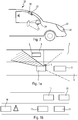
- FIG. 1a a first driving situation where an event requires the attention of the driver of the vehicle 1.
- the driver of the vehicle 1 which circulates in the slow traffic queue 6, has turned on its flashing 5 indicating that it wishes to change lanes in order to overtake the vehicle before 3.
- the driver of the vehicle 1 must think about carrying out several checks. He must first look in the inside and outside rearview mirrors of his vehicle 1 then, he must turn his head and look directly at the fast traffic line 7 in which he wants to fit in order to see if a vehicle is or not 4. If the driver of the vehicle 1 does not carry out all these checks, he will not be able to see the side vehicle 2 which is on the fast lane 7, in his blind spot zone. 4.
- the figure 1b illustrates a second driving situation where an event requires the attention of the driver.
- the vehicles before 11 are caught in a traffic jam. They travel at slow speeds, and can even be stopped.
- the vehicle 10 is traveling at a higher speed.
- the driver of the vehicle 10 goes to see the traffic jam, he will have to adapt his pace. It is important for the driver of the vehicle 10 to be informed as soon as possible of the slowdown so as to be able to slow down progressively and avoid braking suddenly, which could be dangerous in the case where other vehicles would be behind him.
- the figure 1c illustrates a third driving situation where an event requires the attention of the driver.
- the vehicle 20 is equipped with an environmental analysis system arranged so that said vehicle is able to circulate at least partially without action of the driver in an autonomous driving mode.
- the vehicle 20 arrives in a traffic zone 23 prohibiting the circulation in autonomous mode, for example because of the presence of a pedestrian zone near the zone 23.
- This prohibition to circulate in autonomous mode is materialized here by the presence of a panel 21 and by the presence of a checkerboard 22 drawn on the road at the entrance to the zone 23.
- the driver of the vehicle 20, when the vehicle 20 is in autonomous mode may not look at the road. It is therefore possible that he does not see the panel 21 or the checkerboard 22. He must therefore be warned by an adequate warning system that he must perform a take-back action of the vehicle 20 to travel in a mode of manual driving.
- the figure 2 represents a vehicle 30 equipped with a detection system making it possible to respond to the various driving situations set out above by detecting these situations and by transmitting to the driver of the vehicle a warning relating to this event.
- a detection system on the same vehicle 30, namely a system 31 of the ultrasonic sensor type installed in an exterior rearview mirror of the vehicle 30, a system 32 of the laser remote sensing type or LIDAR installed in a front projector of the vehicle 30; and a camera 33 installed in an interior rearview mirror of the vehicle 30.
- the detection system in the warning system according to the invention may comprise one or more of these detection systems 31, 32, 33, the multiplication of these systems allowing to introduce redundancy and thus improve the reliability of the detection.
- the detection system 31 can be positioned outside the vehicle 30, in an outside rearview mirror 34.
- the detection system can also be positioned inside the passenger compartment of the vehicle 30.
- the detection system can be positioned inside the passenger compartment 30.
- detection 32 is positioned in a front projector 35.
- the detection system 33 is positioned in the rearview mirror 36 of the vehicle 30.
- the detection system 31, 32, 33 may be an ultrasonic sensor. It can also be a system receiving signals emitted by vehicles traveling in its environment or issued by infrastructures present in its environment. Alternatively, the detection system 31, 32, 33 may be a camera. The detection system 31, 32, 33 then comprises means for receiving these signals emitted by vehicles traveling in its environment or issued by infrastructures.
- the warning device transmits a warning signal to the driver.
- the warning device can take different forms. It may be a bracelet or a watch, headphones, a motorcycle helmet 40, as shown in FIG. figure 3a or a pair of glasses 50 as shown in the figure 3b .
- the warning signal transmitted by the warning system may be a light signal visible to the driver, a sound signal audible by the driver or a warning signal in the form of vibrations perceptible to the driver.
- the motorcycle helmet 40 has a visor 41 and a light source 42 emitting light which transmits the warning signal in the form of a light signal.
- the pair of spectacles 50 may comprise alone or in combination, a loudspeaker 54 which can transmit a sound signal audible by the driver and / or a piezoelectric system 55 which can transmit a warning signal in the form of vibrations perceptible by the conductor and / or light sources described below which can transmit a visible light signal by the driver.
- the pair of spectacles 50 comprises a first lateral source of light 51 positioned on a branch 56 and a second lateral source of light 52 positioned on the other branch 57.
- the first lateral source of light 51 illuminates a lateral portion 61 of the lens 58.
- the second lateral light source 52 illuminates a lateral portion 62 of the lens 59.
- the pair of spectacles 50 also comprises a first central light source 53a which illuminates a central portion 63 of the lens 58 and a second source central light 53b which illuminates a central portion 64 of the glass 59.
- the glasses 57 and 58 guide the light emitted by the light sources 51, 52, 53a, 53b from a coupling face to a decoupling surface having a surface coating or texturing which diffuses the light to at least one eye of the driver .
- the warning signal is a light signal transmitted by the light sources 51, 52, 53a, 53b. It is transmitted for a determined duration which corresponds to the time between the detection of the event by the detection system 31, 32, 33 and the detection of the disappearance or evolution of the event by the detection system 31, 32, 33.
- the light sources 51, 52, 53a, 53b may be monochromatic light sources, for example red, and the transmitted signal may then be a signal of zero frequency and consist of the activation of the light sources 51, 52, 53a, 53b. It can also be a non-zero frequency signal and consist of a succession of simultaneous activations and deactivations of the sources 51, 52, 53a, 53b so as to form a flashing which can accelerate when the danger or the imminence of an action to be taken by the driver approaches, for the duration determined.
- the light sources 51, 52, 53a, 53b can be activated for signal to the driver that he can not fit into the line in which the detected vehicle is located. It is also possible for the sources 51, 52, 53a, 53b to flash to indicate the proximity of the detected vehicle to the driver.
- the light sources 51, 52, 53a, 53b can be activated when the detection system 31, 32, 33 detects that the vehicle is approaching an area prohibiting vehicle traffic. in autonomous mode. It is also possible that the sources 51, 52, 53a, 53b flash to warn the driver of the imminence of switching to manual mode.
- the light sources 51, 52, 53a, 53b can be activated for any event requiring the attention of the driver such as a change in driving conditions, a slowing of traffic, an obstacle on the road, a toll or the presence a traffic light.
- the light sources 51, 52, 53a, 53b may comprise a plurality of selectively activatable monochromatic emitters emitting at different wavelengths.
- the warning signal can then be a non-zero frequency signal.
- the warning signal may change as the danger or imminence of an action to be taken by the driver approaches.
- a light signal of green light can be emitted by the light sources 51, 52, 53a, 53b when no vehicle is detected by the detection system 31, 32, 33 close to the light source.
- An orange light signal may be emitted by the light sources 51, 52, 53a, 53b when a vehicle is detected by the detection system 31, 32, 33, near the area dead angle of the driver, for example when the vehicle is located within 5 meters of the blind spot area.
- a red light signal can be emitted by the light sources 51, 52, 53a, 53b when a vehicle is detected by the detection system 31, 32, 33 in the blind spot area of the driver. The driver is then informed when it becomes dangerous to overtake by changing the color of the light sources 51, 52, 53a, 53b.
- the light sources 51, 52, 53a, 53b do not emit light when no vehicle near the blind spot area of the driver or in the blind spot area of the driver is detected by the detection system 31, 32, 33.
- the light sources 51, 52, 53a, 53b then emit light only when the danger is near.
- the light sources 51, 52, 53a, 53b can emit a green light signal as long as the vehicle can be in autonomous mode, an orange light signal when the vehicle approaching an event requiring manual movement is detected indicating that the driver must be actively preparing to take action to resume control of the vehicle, a red light signal when the vehicle must be in manual mode.
- the light signal can be transmitted to the driver side corresponding to the position of the event relative to the driver.
- the light signal can be transmitted to the driver side corresponding to the position of the event relative to the driver.
- the detection system 31, 32, 33 In order for the information picked up by the detection system 31, 32, 33 to be transmitted to the pair of spectacles 50, the latter is equipped with means 65 for receiving signals that are transmitted by transmission means of the system. detection 31, 32, 33 so that the pair of glasses 50 communicates with the detection system 31, 32, 33 by a wireless link, in particular by a bluetooth link or wifi.
- the signals emitted by the transmission means 65 of the detection system 31, 32, 33 can be sent to the vehicle 30 and the vehicle 30 can in turn transmit these signals to the detection system 31, 32, 33 via a link wireless.
- the warning device 40, 50 may also comprise means mounted reversibly on an object carried by the driver.
- the figure 4a represents a first embodiment of a fastening means in the form of a spring fastening means 90 which can for example be fixed on a pair of glasses shown in this figure by a branch 95.
- the spring fastening means 90 includes a first movable tab 91 and a second movable tab 92 articulated through the hinge 93.
- a spring 94 also connects the two movable tabs 91, 92.
- the spring is compressed and exerts a spring. restoring force between the two movable tabs 91, 92 so that the movable tabs 91, 92 are drawn against each other.
- a force opposing the restoring force is exerted, a space between the movable tabs 91, 92 is formed.
- An object such as a limb 95 of a pair of spectacles can then be positioned between the movable tabs 91, 92.
- the movable tabs 91, 92 closes around branch 95 positioned between the tabs 91, 92, so that it is enclosed.
- the spring fastening means is then fixed on the branch 95 of the pair of spectacles.
- a receiver 97 is also attached to the spring-loaded fastener 90.
- the receiver 97 can receive the information detected and transmitted by the detection system 31, 32, 33 so as to be able to trigger the activation of a light source 96 attached to the spring fastening means 90.
- the light source 96 is attached to the spring fastening means 90 so that when the spring fastening means 90 is attached to the leg 95 of the pair of spectacles, the light source 96 emits light in the direction of a glass of the pair of glasses to be reflected to a driver's eye.
- the light source no longer needs to be fixed in advance to the branch of glasses.
- the light emitted by the light source 96 is then instantly visible by the driver. This can then react as soon as a change in traffic conditions requiring the immediate attention of the driver is detected.
- the figure 4b represents a second embodiment of a fastening means in the form of an elastic fastening means 70 that can for example be fixed on a pair of spectacles shown in this figure by a branch 72.
- the elastic fastening means 70 comprises a fixed tab 74 and a movable tab 75 connected by a fastening element 76 and a lever 71.
- the fastening element 76 comes from the fixed tab 74 at one of its ends. and makes it possible to fix the mobile tab 75 in front of the fixed tab 74 at one of its ends.
- the lever 71 is also attached to the fastening means via the fastening element 76. It is movable between two positions. A loosened position as shown on the figure 4b allowing the fixed tab 74 and the mobile tab 75 to be moved away and thus to position the branch 72 between these two tabs 74, 75 and a constricted position where the fixed tab 74 and the mobile tab 75 engage the branch 72.
- a receiver 80 is also attached to the elastic fastening means 70.
- the receiver 80 can then receive the information detected and transmitted by the detection system 31, 32, 33 in order to trigger the activation of a light source 79 attached to the receiver.
- the light source 79 is attached to the elastic fastening means 70 so that when the elastic fastening means is attached to the branch 72 of the pair of spectacles, the light source 79 emits light by direction of a glass of the pair of glasses to be reflected to a driver's eye. The light source then no longer needs to be fixed in advance to the glasses branch.
- the light emitted by the light source 79 is then instantly visible by the driver. This one can then react as soon as a change in traffic conditions requiring the immediate attention of the driver is detected.
Landscapes
- Engineering & Computer Science (AREA)
- Mechanical Engineering (AREA)
- Transportation (AREA)
- Chemical & Material Sciences (AREA)
- Combustion & Propulsion (AREA)
- Physics & Mathematics (AREA)
- General Physics & Mathematics (AREA)
- Theoretical Computer Science (AREA)
- General Engineering & Computer Science (AREA)
- Automation & Control Theory (AREA)
- Human Computer Interaction (AREA)
- Optics & Photonics (AREA)
- Multimedia (AREA)
- Traffic Control Systems (AREA)
- Emergency Alarm Devices (AREA)
Abstract
Description
- L'invention concerne un système d'avertissement d'un conducteur de véhicule automobile.
- Il existe des conditions de circulations d'un véhicule automobile qui nécessitent un système d'avertissement du conducteur du véhicule pour capter son attention de sorte à ce qu'il adapte son mode de circulation. C'est notamment le cas lorsque le véhicule se retrouve dans une situation dangereuse. Une situation dangereuse peut survenir par exemple lorsqu'il y a un changement brusque des conditions de circulation, lorsqu'il y a un ralentissement brutal de la circulation, lorsqu'un objet difficilement visible par le conducteur est présent sur la voie de circulation ou lorsque le conducteur souhaite changer de voie de circulation. Il est important pour la sécurité des passagers que le conducteur du véhicule détecte ces situations potentiellement dangereuses pour pouvoir intervenir si nécessaire.
- C'est également le cas lorsque le véhicule pénètre dans une zone requérant un mode de conduite particulier. Il existe ainsi des zones de circulation à vitesse réduite, nécessitant un ralentissement du véhicule, ou encore des zones de circulation dites restreintes, interdisant le passage de véhicules équipés de moteur thermique ou encore de système de circulation dit autonome.
- Dans ce contexte, plusieurs systèmes existent et permettent d'aider le conducteur à être informé des conditions de circulation dans lesquelles il se trouve. Par exemple, le véhicule peut notamment être équipé d'une caméra qui capte des images de l'environnement dans lequel se trouve le véhicule et qui est reliée à un système permettant de transmettre ces images à un écran situé à proximité du tableau de bord.
- Par ailleurs, dans le cas d'un changement de file de circulation, le conducteur doit regarder dans les rétroviseurs intérieurs et extérieurs au véhicule afin de savoir s'il peut se déporter en toute sécurité. Le conducteur doit en plus tourner la tête sur le côté où se situe la voie pour regarder en vision directe si un véhicule ne se situe pas dans la zone qui n'est pas visible dans les rétroviseurs, appelée zone d'angle mort ou angle mort.
- Ainsi, dans tous les dispositifs connus, le conducteur est obligé d'arrêter de regarder la route afin de pouvoir regarder sur le tableau de bord, dans les rétroviseurs ou sur le côté en vision directe. Il est donc obligé de déporter son attention de la route et d'orienter son regard dans la direction du dispositif pour avoir accès à l'information. Or, il peut arriver que le conducteur ne pense pas à déporter son regard, notamment dans le cas de conditions de circulation nécessitant une grande concentration de la part du conducteur ou encore dans le cas d'un véhicule dit autonome dans lequel le conducteur peut détacher son attention de la conduite. Le changement de conditions de circulation est donc détecté trop tard par le conducteur, voire n'est pas du tout détecté, ce qui pose un problème de sécurité.
- Un but de l'invention est donc de fournir un système d'avertissement d'un conducteur de véhicule permettant de diminuer le temps de réponse d'un conducteur face à un changement de conditions de circulation nécessitant son attention immédiate.
- A cet effet, on prévoit selon l'invention un système d'avertissement d'un conducteur d'un véhicule d'un événement dans l'environnement du véhicule, comprenant :
- un système de détection apte à détecter un événement intervenant dans l'environnement du véhicule ;
- un dispositif d'avertissement destiné à être porté par le conducteur et connecté au système de détection ;
- Un tel système d'avertissement permet d'avertir le conducteur d'un changement des conditions de circulation immédiatement et à tout moment, puisque le dispositif d'avertissement est porté par le conducteur. Il est donc suffisamment proche du conducteur pour que celui-ci puisse être averti dès le changement de conditions de circulation de sorte à pouvoir adapter la conduite du véhicule de façon immédiate.
- Le système de détection peut être positionné à l'extérieur de l'habitacle du véhicule. Il peut par exemple être positionné dans un rétroviseur extérieur du véhicule. Alternativement, le système de détection est positionné à l'intérieur de l'habitacle du véhicule. Par exemple, il peut être positionné dans un projecteur ou dans un feu arrière du véhicule ou encore dans un rétroviseur intérieur du véhicule.
- Le système de détection peut être un capteur ultrasons. Par exemple, le système de détection est un système Lidar. Alternativement, le système de détection est un système apte à recevoir un signal émis par un véhicule en circulation dans l'environnement du véhicule. Selon une variante, le système de détection est un système apte à recevoir un signal d'une infrastructure par l'intermédiaire d'une liaison Wifi, Wimax, 3G ou 4G. En variante encore, le système de détection peut être une caméra. En variante encore, le système de détection peut être une combinaison de plusieurs des systèmes de détection cités ci-dessus, identiques ou distincts.
- Avantageusement, le dispositif d'avertissement comprend une source de lumière agencée pour transmettre ledit signal d'avertissement sous la forme d'un signal lumineux visible par le conducteur. La source de lumière peut être une source de lumière monochromatique, par exemple rouge. Alternativement, la source de lumière comporte une pluralité d'émetteurs monochromatiques activables sélectivement et émettant à des longueurs d'ondes différentes. En particulier, la source de lumière peut être une source à semi-conducteur émettrice de lumière. Avantageusement, la source de lumière peut être une diode électroluminescente (LED).
- Alternativement, le dispositif d'avertissement comprend un haut parleur agencé pour transmettre ledit signal d'avertissement sous la forme d'un signal sonore audible par le conducteur.
- Alternativement, le dispositif d'avertissement est apte à transmettre ledit signal d'avertissement sous la forme de vibrations perceptibles par le conducteur. Par exemple, le dispositif d'avertissement comprend un système piézoélectrique.
- Si on le souhaite, le dispositif d'avertissement peut être apte à transmettre plusieurs types de signaux d'avertissement, notamment de façon simultanée, parmi ceux cités ci-dessus.
- Avantageusement, le dispositif d'avertissement est agencé pour transmettre le signal d'avertissement pendant une durée déterminée, ladite durée déterminée correspondant au temps entre la détection de l'événement par le système de détection et la détection d'une disparition ou d'une évolution dudit événement par le système de détection. Le conducteur est ainsi informé pendant toute la durée de la présence de l'événement.
- Selon une variante, le dispositif d'avertissement est agencé pour que le signal d'avertissement soit un signal de fréquence nulle. Il peut par exemple consisté en l'activation de la source de lumière, du haut parleur ou des vibrations.
- Selon une autre variante, le dispositif d'avertissement est agencé pour que le signal d'avertissement soit un signal de fréquence non nulle. Le signal d'avertissement peut alors être un signal périodique de fréquence fixe, ou un signal apériodique évolutif.
- Avantageusement, le dispositif d'avertissement est agencé pour modifier une ou plusieurs caractéristiques du signal d'avertissement pendant ladite durée déterminée. Le dispositif d'avertissement peut modifier la longueur d'onde émise par la source de lumière, la fréquence du signal sonore émis par le haut parleur, l'intensité du signal ou la fréquence du signal.
- Avantageusement, le dispositif d'avertissement est agencé pour modifier la ou les caractéristiques du signal d'avertissement le long de ladite durée prédéterminée en fonction d'une détection d'une évolution de l'événement au cours de ladite durée déterminée par le système de détection. Le dispositif d'avertissement peut ainsi adapter les caractéristiques du signal en fonction de la dangerosité de l'événement ou encore en fonction de sa proximité avec le véhicule, de sorte à ce que le conducteur puisse anticiper cet événement en adaptant sa conduite de façon progressive.
- Préférentiellement, le dispositif d'avertissement est agencé pour transmettre ledit signal d'avertissement au conducteur lorsqu'un événement nécessitant l'attention du conducteur est détecté par le système de détection. Par exemple, un événement nécessitant une modification ou une adaptation de la conduite du véhicule par le conducteur, comme par exemple la direction ou la vitesse du véhicule, en fonction dudit événement.
- Avantageusement, le dispositif d'avertissement est agencé pour transmettre ledit signal d'avertissement d'un côté du conducteur correspondant à la position dudit événement par rapport au conducteur. Le conducteur est ainsi directement averti de la position de l'événement par rapport à lui-même.
- Selon une variante, le dispositif d'avertissement est agencé pour transmettre ledit signal d'avertissement au conducteur lorsque la présence d'un véhicule dans une zone d'angle mort du conducteur est détectée par le système de détection.
- Avantageusement, le dispositif d'avertissement est agencé pour transmettre un premier signal d'avertissement donné lorsque le système de détection ne détecte aucun véhicule dans la zone d'angle mort du conducteur, un deuxième signal d'avertissement donné lorsque le système de détection détecte un véhicule a proximité de la zone d'angle mort du conducteur, c'est-à-dire lorsque le véhicule est visible dans un rétroviseur extérieur, par exemple lorsque le véhicule se situe à moins de 10 mètres de la zone d'angle mort, notamment moins de 5 mètres, un troisième signal d'avertissement donné lorsque le système de détection détecte un véhicule dans la zone d'angle mort du conducteur. Par exemple, le premier signal d'avertissement peut être un signal lumineux de couleur verte, le deuxième signal d'avertissement peut être un signal lumineux de couleur orange et le troisième signal d'avertissement peut être un signal lumineux de couleur rouge. Le dispositif d'avertissement avertit donc dans ce cas le conducteur de l'arrivée et de la disparition du danger, à savoir un véhicule dépassant non visible, de façon simple et immédiatement compréhensible.
- Alternativement, aucun signal d'avertissement n'est émis lorsque le système de détection ne détecte aucun véhicule dans la zone d'angle mort du conducteur.
- Avantageusement, le signal d'avertissement est transmis au conducteur lorsque la présence d'un danger, un changement des conditions de conduite, un ralentissement de la circulation, un obstacle sur la route, un péage ou la présence d'un feu de signalisation est détecté par le système de détection.
- Selon une autre variante, le véhicule est équipé d'un système d'analyse de l'environnement agencé pour que ledit véhicule soit apte à circuler au moins partiellement sans action du conducteur dans un mode de conduite, appelé mode autonome. Préférentiellement, le système de détection comprend le système d'analyse de l'environnement. Il peut notamment s'agir entre autre d'un ensemble de capteurs de type LIDAR, RADAR, caméra, capteur infrarouge, permettant au véhicule d'appréhender la scène de route de sorte à pouvoir y circuler seul sans intervention du conducteur, en adaptant de façon autonome et dynamique sa vitesse et sa trajectoire.
- Avantageusement, le dispositif d'avertissement est agencé pour transmettre ledit signal d'avertissement au conducteur lorsque celui-ci doit entreprendre une action de reprise de commandes du véhicule, le véhicule circulant alors dans un mode de conduite, appelé mode manuel. Par exemple, le dispositif d'avertissement est agencé pour transmettre ledit signal d'avertissement au conducteur lorsque le véhicule en mode autonome entre dans une zone interdisant la circulation de véhicule en mode autonome. Dans ce cas, le dispositif transmet donc au conducteur une information lui indiquant qu'il est nécessaire d'arrêter le mode de conduite autonome et de reprendre un mode de conduite manuelle.
- Avantageusement, le dispositif d'avertissement est apte à communiquer avec le véhicule par une liaison sans fil. La liaison sans fil peut être une liaison bluetooth, wifi, lifi ou radio. Il est ainsi possible au conducteur de porter ledit dispositif d'avertissement sans que ses mouvements soient gênés par des câbles.
- Préférentiellement, le véhicule et le dispositif d'avertissement comportent des moyens d'émission et de réception de signaux pour réaliser la liaison sans fil. Alternativement, le dispositif d'avertissement est apte à communiquer avec le véhicule par une liaison filaire.
- Dans un premier exemple, le dispositif d'avertissement est un bracelet ou une montre. Dans cet exemple, il peut être avantageux que le signal d'avertissement soit un signal vibratoire, facilement perceptible via le poignet du conducteur.
- Dans un deuxième exemple, le dispositif d'avertissement sont des écouteurs. Dans cet exemple, il peut être avantageux que le signal d'avertissement soit un signal sonore, immédiatement perceptible via les conduits auditifs du conducteur.
- Dans un troisième exemple, le dispositif d'avertissement est un casque de moto. Par exemple, le casque de moto comporte une visière et une source de lumière apte à émettre de la lumière vers la visière. Dans ce cas, le signal d'avertissement consiste en un signal lumineux immédiatement perceptible par le conducteur, dont le champ de vision englobe cette visière.
- Dans un quatrième exemple, le dispositif d'avertissement est une paire de lunettes. Dans cet exemple, il peut être avantageux que le signal d'avertissement soit un signal lumineux, immédiatement perceptible via les yeux du conducteur.
- Avantageusement, la paire de lunettes comporte des moyens d'avertissement pour transmettre ledit signal d'avertissement au conducteur, lesdits moyens d'avertissement étant positionnés sur au moins une branche de la paire de lunettes et/ou sur la monture centrale de la paire de lunettes.
- Préférentiellement, les moyens d'avertissement comportent une première source latérale de lumière, portée par ladite branche pour émettre le signal lumineux d'avertissement,
La première source latérale de lumière est configurée pour éclairer au moins une partie d'un verre, dite portion latérale. Le signal lumineux est dans ce cas avantageusement projeté ou diffusé sur ce verre de sorte à être immédiatement visible par le conducteur. - Avantageusement, les moyens d'avertissement comportent une deuxième source latérale de lumière portée par l'autre branche de la paire de lunettes pour émettre un signal lumineux d'avertissement, et configurée pour éclairer au moins une partie de l'autre verre. Cette caractéristique permet d'éclairer l'ensemble des verres de sorte à ce que les deux yeux du conducteur captent le signal.
- Avantageusement, les moyens d'avertissement comportent une source centrale de lumière, portée par la monture centrale pour émettre le signal lumineux d'avertissement. La source centrale de lumière est configurée pour éclairer au moins une partie d'un verre, dite partie centrale. Cette caractéristique offre l'avantage de pouvoir éclairer la totalité du verre tout en permettant de modifier la taille de la surface éclairée (par allumage ou extinction de la source centrale et/ou de la ou des sources latérales) de façon à adapter le signal en fonction de l'événement et par exemple de sa proximité par rapport au véhicule.
- Préférentiellement, la première source latérale de lumière et la source centrale de lumière sont aptes à éclairer le même verre, la partie latérale étant distincte de la partie centrale.
- Avantageusement, le (ou les) verre(s) éclairé(s) comporte une face de couplage et une face de découplage, le verre étant agencé pour guider la lumière émise par la première source latérale de lumière et/ou la deuxième source latérale de lumière et/ou la source centrale de lumière depuis la face de couplage vers la face de découplage.
- Préférentiellement, la face de découplage comporte des moyens de découplage apte à diffuser la lumière vers au moins un oeil du conducteur. Les moyens de découplage comprennent un revêtement ou une texturation de surface. Dans ce mode de réalisation, la lumière est donc avantageusement diffusée par le verre lui-même, ce qui permet d'éviter un éblouissement du conducteur.
- Avantageusement, le verre est agencé pour réfléchir la lumière émise par la première source latérale de lumière et/ou la deuxième source latérale de lumière et/ou la source centrale de lumière vers au moins un oeil du conducteur. Dans ce mode de réalisation, la lumière est avantageusement réfléchie par le verre, ce qui permet d'obtenir un signal d'avertissement lumineux de plus grande intensité.
- Alternativement, la première source latérale de lumière, et le cas échéant, la deuxième source latérale de lumière et/ou la source centrale de lumière sont agencées pour éclairer directement vers au moins un oeil du conducteur. Par directement, on entend que les lunettes ne sont pas utilisées comme un dioptre. La lumière émise atteint donc l'oeil du conducteur sans être déviée par les lunettes. En revanche, il est possible d'utiliser un réflecteur pour orienter la lumière vers au moins un oeil du conducteur.
- Avantageusement, le dispositif d'avertissement comprend des moyens agencés pour être montés, de façon réversible, sur un objet porté par le conducteur. Cette caractéristique permet ainsi au conducteur de fixer ou non, selon ses besoins, le dispositif d'avertissement à un objet qu'il porte sur lui au quotidien.
- Dans une première variante, le dispositif d'avertissement comprend des moyens de fixation élastique sur une paire de lunettes. Par exemple, un boîtier comprenant une source de lumière est attaché aux moyens élastiques de sorte que la source de lumière soit positionnée pour émettre de la lumière en direction d'un verre de la paire de lunettes pour y être réfléchie vers un oeil du conducteur.
- Dans une deuxième variante, le dispositif d'avertissement comprend des moyens de fixation adhésive sur une visière d'un casque.
- D'autres caractéristiques et avantages de la présente invention apparaitront plus clairement à l'aide de la description et des dessins parmi lesquels :
- la
figure 1a représente schématiquement en vue de haut une situation de conduite où un véhicule est présent dans la zone d'angle mort du conducteur ; - la
figure 1b représente schématiquement en vue de haut une situation de conduite où un ralentissement de la circulation a lieu ; - la
figure 1c représente schématiquement une situation de conduite en vue de haut où un véhicule entre dans une zone interdisant la circulation de véhicule en mode autonome ; - la
figure 2 représente un véhicule équipé d'un système de détection - la
figure 3a représente un casque de moto utilisé comme système d'avertissement - la
figure 3b représente une paire de lunettes utilisée comme système d'avertissement - la
figure 4a représente un premier mode de réalisation d'un moyen de fixation agencé pour être monté sur un objet porté par le conducteur - la
figure 4b représente un deuxième mode de réalisation d'un moyen de fixation agencé pour être monté sur un objet porté par le conducteur - On a illustré sur la
figure 1a une première situation de conduite où un événement nécessite l'attention du conducteur du véhicule 1. En effet, le conducteur du véhicule 1, qui circule dans la file de circulation lente 6, a enclenché son clignotant 5 indiquant qu'il souhaite changer de file de circulation afin de pouvoir dépasser le véhicule avant 3. Pour pouvoir effectuer son dépassement en toute sécurité, le conducteur du véhicule 1 doit penser à réaliser plusieurs contrôles. Il doit tout d'abord regarder dans les rétroviseurs intérieurs et extérieurs de son véhicule 1 puis, il doit tourner la tête et regarder directement la file de circulation rapide 7 dans laquelle il veut s'insérer afin de voir si un véhicule se trouve ou non dans sa zone d'angle mort 4. Si le conducteur du véhicule 1 n'effectue pas tous ces contrôles, il ne pourra pas voir le véhicule latéral 2 qui se trouve sur la file de circulation rapide 7, dans sa zone d'angle mort 4. Il se déportera et entrera en collision avec le véhicule latéral 2. Dans cette situation de conduite, il est donc important que le conducteur du véhicule 1 soit averti de la présence du véhicule latéral 2 lui interdisant tout dépassement. Le conducteur du véhicule 1 doit donc adapter sa vitesse pour ne pas entrer en collision avec le véhicule avant 3 tant que le véhicule latéral 2 ne l'a pas dépassé. - La
figure 1b illustre une deuxième situation de conduite où un événement nécessite l'attention du conducteur. Dans cette situation, les véhicules avant 11 sont pris dans un embouteillage. Ils circulent selon des vitesses lentes, et peuvent même être à l'arrêt. Le véhicule 10 circule à une allure plus élevée. Dès que le conducteur du véhicule 10 va voir l'embouteillage, il va devoir adapter son allure. Il est important que le conducteur du véhicule 10 soit informé le plus tôt possible du ralentissement afin de pouvoir ralentir progressivement et éviter de freiner brusquement, ce qui pourrait être dangereux dans le cas où d'autres véhicules se situeraient derrière lui. - La
figure 1c illustre une troisième situation de conduite où un événement nécessite l'attention du conducteur. Dans cet exemple, le véhicule 20 est équipé d'un système d'analyse de l'environnement agencé pour que ledit véhicule soit apte à circuler au moins partiellement sans action du conducteur dans un mode de conduite autonome. Le véhicule 20 arrive dans une zone de circulation 23 interdisant la circulation en mode autonome, par exemple du fait de la présence d'une zone piétonne à proximité de la zone 23. Cette interdiction de circuler en mode autonome est matérialisée ici par la présence d'un panneau 21 et par la présence d'un damier 22 dessiné sur la route à l'entrée de la zone 23. Le conducteur du véhicule 20, lorsque le véhicule 20 est en mode autonome, peut ne pas regarder la route. Il est donc possible qu'il ne voit pas le panneau 21 ou le damier 22. Il doit donc être averti par un système d'avertissement adéquat qu'il doit réaliser une action de reprise de commandes du véhicule 20 pour circuler dans un mode de conduite manuel. - La
figure 2 représente un véhicule 30 équipé d'un système de détection permettant de répondre aux différentes situations de conduite exposées ci-dessus en détectant ces situations et en transmettant au conducteur du véhicule 30 un avertissement relatif à cet événement. On a représenté sur cettefigure 2 plusieurs systèmes de détection sur le même véhicule 30, à savoir un système 31 de type capteur à ultrason installé dans un rétroviseur extérieur du véhicule 30, un système 32 de type télédétection par laser ou LIDAR installé dans un projecteur avant du véhicule 30 ; et une caméra 33 installée dans un rétroviseur intérieur du véhicule 30. Le système de détection dans le système d'avertissement selon l'invention peut comprendre l'un ou plusieurs de ces systèmes de détection 31, 32, 33, la multiplication de ces systèmes permettant d'introduire de la redondance et donc d'améliorer la fiabilité de la détection. Le système de détection 31 peut être positionné à l'extérieur du véhicule 30, dans un rétroviseur extérieur 34. Le système de détection peut également être positionné à l'intérieur de l'habitacle du véhicule 30. Dans un premier exemple, le système de détection 32 est positionné dans un projecteur avant 35. Dans un deuxième exemple, le système de détection 33 est positionné dans le rétroviseur intérieur 36 du véhicule 30. - Plusieurs systèmes de détection 31, 32, 33 peuvent être utilisés dans le cadre de l'invention. Le système de détection 31, 32, 33 peut être un capteur ultrasons. Il peut également être un système recevant des signaux émis par les véhicules circulant dans son environnement ou émis par des infrastructures présentes dans son environnement. En variante, le système de détection 31, 32, 33 peut être une caméra. Le système de détection 31, 32, 33 comporte alors des moyens de réception de ces signaux émis par les véhicules circulant dans son environnement ou émis par des infrastructures.
- Une fois que le système de détection 31, 32, 33 a détecté un événement nécessitant l'attention du conducteur intervenant dans l'environnement du véhicule, tel que par exemple représenté sur l'une des
figures 1a, 1b et1c , le dispositif d'avertissement transmet un signal d'avertissement au conducteur. - Le dispositif d'avertissement peut prendre différentes formes. Il peut s'agir d'un bracelet ou d'une montre, d'écouteurs, d'un casque de moto 40, comme représenté à la
figure 3a ou d'une paire de lunettes 50 comme présentée à lafigure 3b . Et le signal d'avertissement transmis par le système d'avertissement peut être un signal lumineux visible par le conducteur, un signal sonore audible par le conducteur ou un signal d'avertissement sous la forme de vibrations perceptibles par le conducteur. - Par exemple, comme illustré en
figure 3a , le casque de moto 40 comporte une visière 41 et une source de lumière 42 émettant de la lumière et qui transmet le signal d'avertissement sous la forme d'un signal lumineux. - Selon un autre exemple illustré en
figure 3b , la paire de lunettes 50 peut comporter seuls ou en combinaison, un haut parleur 54 qui peut transmettre un signal sonore audible par le conducteur et/ou un système piézoélectrique 55 qui peut transmettre un signal d'avertissement sous la forme de vibrations perceptibles par le conducteur et/ou des source de lumière décrites ci-après qui peuvent transmettre un signal lumineux visible par le conducteur. - Afin de transmettre un signal lumineux, la paire de lunettes 50 comporte une première source latérale de lumière 51 positionnée sur une branche 56 et une deuxième source latérale de lumière 52 positionnée sur l'autre branche 57. La première source latérale de lumière 51 éclaire une partie latérale 61 du verre 58. La deuxième source latérale de lumière 52 éclaire une partie latérale 62 du verre 59. La paire de lunettes 50 comporte également une première source centrale de lumière 53a qui éclaire une partie centrale 63 du verre 58 et une deuxième source centrale de lumière 53b qui éclaire une partie centrale 64 du verre 59.
- Les verres 57 et 58 guident la lumière émise par les sources de lumière 51, 52, 53a, 53b depuis une face de couplage vers une face de découplage comportant un revêtement ou une texturation de surface qui diffuse la lumière vers au moins un oeil du conducteur.
- Le signal d'avertissement est un signal lumineux transmis par les sources de lumière 51, 52, 53a, 53b. Il est transmis pendant une durée déterminée qui correspond au temps entre la détection de l'événement par le système de détection 31, 32, 33 et la détection de la disparition ou de l'évolution de l'événement par le système de détection 31, 32, 33.
- Les sources de lumière 51, 52, 53a, 53b peuvent être des sources de lumière monochromatiques, par exemple rouge et le signal transmis peut alors être un signal de fréquence nulle et consister en l'activation des sources de lumière 51, 52, 53a, 53b. Il peut également être un signal de fréquence non nulle et consister en une succession d'activations et de désactivations simultanées des sources 51, 52, 53a, 53b de sorte à former un clignotement qui peut s'accélérer lorsque le danger ou l'imminence d'une action à entreprendre par le conducteur approche, pendant la durée déterminée.
- Par exemple, dans le cas où la présence d'un véhicule dans la zone d'angle mort du conducteur est détectée par le système de détection 31, 32, 33, les sources de lumière 51, 52, 53a, 53b peuvent être activées pour signaler au conducteur qu'il ne peut pas s'insérer dans la file dans laquelle se situe le véhicule détecté. Il est également possible que les sources 51, 52, 53a, 53b clignotent pour signaler la proximité du véhicule détecté au conducteur.
- Dans le cas où le véhicule circule dans un mode autonome, les sources de lumière 51, 52, 53a, 53b peuvent être activées lorsque le système de détection 31, 32, 33 détecte que le véhicule approche d'une zone interdisant la circulation de véhicule en mode autonome. Il est également possible que les sources 51, 52, 53a, 53b clignotent pour signaler au conducteur l'imminence de passer en mode manuel.
- Les sources de lumière 51, 52, 53a, 53b peuvent être activées pour tout événement nécessitant l'attention du conducteur tel qu'un changement des conditions de conduite, un ralentissement de la circulation, un obstacle sur la route, un péage ou la présence d'un feu de signalisation.
- Alternativement, les sources de lumière 51, 52, 53a, 53b peuvent comporter une pluralité d'émetteurs monochromatiques activables sélectivement et émettant à des longueurs d'onde différentes. Le signal d'avertissement peut alors être un signal de fréquence non nulle. Le signal d'avertissement peut évoluer à mesure que le danger ou l'imminence d'une action à entreprendre par le conducteur approche.
- Par exemple, lorsque le véhicule circule, un signal lumineux de lumière verte peut être émis par les sources de lumière 51, 52, 53a, 53b lorsqu'aucun véhicule n'est détecté par le système de détection 31, 32, 33 proche de la zone d'angle mort du conducteur ou dans la zone d'angle mort du conducteur. Un signal lumineux de couleur orange peut être émis par les sources de lumière 51, 52, 53a, 53b lorsqu'un véhicule est détecté par le système de détection 31, 32, 33, à proximité de la zone d'angle mort du conducteur, par exemple lorsque le véhicule est situé à moins de 5 mètres de la zone d'angle mort. Et, un signal lumineux de couleur rouge peut être émis par les sources de lumière 51, 52, 53a, 53b lorsqu'un véhicule est détecté par le système de détection 31, 32, 33 dans la zone d'angle mort du conducteur. Le conducteur est alors informé quand il devient dangereux d'effectuer un dépassement grâce au changement de couleur des sources de lumière 51, 52, 53a, 53b.
- Il est également possible que les sources de lumière 51, 52, 53a, 53b n'émettent pas de lumière lorsqu'aucun véhicule à proximité de la zone d'angle mort du conducteur ou dans la zone d'angle mort du conducteur n'est détecté par le système de détection 31, 32, 33. Les sources de lumière 51, 52, 53a, 53b n'émettent alors de la lumière que lorsque le danger est proche.
- Dans le cas où le véhicule circule dans un mode autonome, les sources de lumière 51, 52, 53a, 53b peuvent émettre un signal lumineux de couleur verte tant que le véhicule peut être en mode autonome, un signal lumineux de couleur orange lorsque le véhicule s'approche de un événement nécessitant de circuler en mode manuel est détecté indiquant que le conducteur doit se préparer activement à entreprendre une action de reprise de commandes du véhicule, un signal lumineux de couleur rouge lorsque le véhicule doit obligatoirement être en mode manuel.
- De plus, le signal lumineux peut être transmis du côté du conducteur correspondant à la position de l'événement par rapport au conducteur. Ainsi, lorsqu'un véhicule est présent dans la zone d'angle mort du conducteur, seul le verre se trouvant du côté du véhicule se trouvant dans la zone d'angle mort peut être éclairé. Lorsque le véhicule se trouvant dans la zone d'angle mort est à la gauche du conducteur, seule la partie latérale 61 du verre 58 est éclairée et optionnellement la partie centrale 63 du verre 58 est éclairée. Le conducteur peut alors savoir immédiatement de quelle direction provient le danger.
- Pour que l'information captée par le système de détection 31, 32, 33 soit transmise à la paire de lunettes 50, celle-ci est équipée d'un moyen de réception 65 des signaux qui sont émis par des moyens d'émission du système de détection 31, 32, 33 de sorte que la paire de lunettes 50 communique avec le système de détection 31, 32, 33 par une liaison sans fil, notamment par une liaison bluetooth ou wifi. Alternativement, les signaux émis par les moyens d'émission 65 du système de détection 31, 32, 33 peuvent être envoyés au véhicule 30 et le véhicule 30 peut à son tour transmettre ces signaux au système de détection 31, 32, 33 par une liaison sans fil.
- Le dispositif d'avertissement 40, 50 peut également comprendre des moyens montés de façon réversible sur un objet porté par le conducteur.
- La
figure 4a représente un premier mode de réalisation d'un moyen de fixation prenant la forme d'un moyen de fixation à ressort 90 pouvant par exemple être fixé sur une paire de lunettes représentée sur cette figure par une branche 95. - Le moyen de fixation à ressort 90 comporte une première patte mobile 91 et une deuxième patte mobile 92 articulées par l'intermédiaire de l'articulation 93. Un ressort 94 relie également les deux pattes mobiles 91, 92. Le ressort est comprimé et exerce une force de rappel entre les deux pattes mobiles 91, 92 de sorte que les pattes mobiles 91, 92 soient attirées l'une contre l'autre. Lorsqu'une force opposée à la force de rappel est exercée, un espace entre les pattes mobiles 91, 92 est formé. Un objet tel qu'une branche 95 d'une paire de lunettes peut alors être positionnée entre les pattes mobiles 91, 92. Lorsque la force opposée à la force de rappel n'est plus exercée, les pattes mobiles 91, 92 se referme autour de la branche 95 positionné entre les pattes 91, 92, de sorte à ce qu'il soit enserré. Le moyen de fixation à ressort est alors fixé sur la branche 95 de la paire de lunettes.
- Un récepteur 97 est également attaché au moyen de fixation à ressort 90. Le récepteur 97 peut recevoir les informations détectées et transmises par le système de détection 31, 32, 33 afin de pourvoir déclencher l'activation d'une source de lumière 96 attachée au moyen de fixation à ressort 90. La source de lumière 96 est attachée au moyen de fixation à ressort 90 de sorte que lorsque le moyen de fixation à ressort 90 est fixé sur la branche 95 de la paire de lunettes, la source de lumière 96 émet de la lumière en direction d'un verre de la paire de lunettes pour y être réfléchie vers un oeil du conducteur. La source de lumière n'a alors plus besoin d'être fixée au préalable à la branche de lunettes. La lumière émise par la source de lumière 96 est alors visible instantanément par le conducteur. Celui-ci peut alors réagir dès qu'un changement des conditions de circulation nécessitant l'attention immédiate du conducteur est détecté.
- La
figure 4b représente un deuxième mode de réalisation d'un moyen de fixation prenant la forme d'un moyen de fixation élastique 70 pouvant par exemple être fixé sur une paire de lunettes représentée sur cette figure par une branche 72. - Le moyen de fixation élastique 70 comporte une patte fixe 74 et une patte mobile 75 reliées par un élément d'attache 76 et un levier 71. L'élément d'attache 76 est issue de la patte fixe 74 à l'une de ses extrémités et permet de venir fixer la patte mobile 75 en face de la patte fixe 74 à l'une de ses extrémités. Le levier 71 est également rattaché au moyen de fixation par l'intermédiaire de l'élément d'attache 76. Il est mobile entre deux positions. Une position desserrée comme représentée sur la
figure 4b permettant d'éloigner la patte fixe 74 et la patte mobile 75 et de positionner ainsi la branche 72 entre ces deux pattes 74, 75 et une position resserrée où la patte fixe 74 et la patte mobile 75 viennent enserrer la branche 72. L'extrémité de contact 78 du levier 71, opposée à l'extrémité libre 77 est en contact avec une des pattes. Le levier 71 passe de la position desserrée à la position resserrée lorsqu'une force est appliquée à son extrémité libre 77, l'extrémité de contact 78 vient alors appuyer contre la patte mobile 75 qui vient alors enserrer la branche 72 en coopération avec la patte fixe 74. - Un récepteur 80 est également attaché au moyen de fixation élastique 70. Le récepteur 80 peut alors recevoir les informations détectées et transmises par le système de détection 31, 32, 33 afin de pouvoir déclencher l'activation d'une source de lumière 79 attachée au moyen de fixation élastique 70. La source de lumière 79 est attachée au moyen de fixation élastique 70 de sorte que lorsque le moyen de fixation élastique est fixé sur la branche 72 de la paire de lunettes, la source de lumière 79 émet de la lumière en direction d'un verre de la paire de lunettes pour y être réfléchie vers un oeil du conducteur. La source de lumière n'a alors plus besoin d'être fixée au préalable à la branche de lunettes. La lumière émise par la source de lumière 79 est alors visible instantanément par le conducteur. Celui-ci peut alors réagir dès qu'un changement des conditions de circulation nécessitant l'attention immédiate du conducteur est détecté.
Claims (14)
- Système d'avertissement d'un conducteur d'un véhicule (30) d'un événement dans l'environnement du véhicule, comprenant :un système de détection (31 ; 32 ; 33) apte à détecter un événement intervenant dans l'environnement du véhicule (30) ;un dispositif d'avertissement (40 ; 50) destiné à être porté par le conducteur et connecté au système de détection (31 ; 32 ; 33) ;caractérisé en ce que le dispositif d'avertissement (40 ; 50) est agencé pour transmettre un signal d'avertissement au conducteur lorsqu'un événement est détecté par le système de détection (31 ; 32 ; 33).
- Système d'avertissement d'un conducteur d'un véhicule (30) selon la revendication précédente, caractérisé en ce que le dispositif d'avertissement (40 ; 50) comprend une source de lumière (42 ; 51, 52, 53a, 53b) agencée pour transmettre ledit signal d'avertissement sous la forme d'un signal lumineux visible par le conducteur.
- Système d'avertissement d'un conducteur d'un véhicule (30) selon la revendication 1, caractérisé en ce que le dispositif d'avertissement (40 ; 50) comprend un haut parleur (54) agencé pour transmettre ledit signal d'avertissement sous la forme d'un signal sonore audible par le conducteur.
- Système d'avertissement d'un conducteur d'un véhicule (30) selon la revendication 1, caractérisé en ce que le dispositif d'avertissement (40 ; 50) est apte à transmettre ledit signal d'avertissement sous la forme de vibrations perceptibles par le conducteur.
- Système d'avertissement d'un conducteur d'un véhicule (30) selon l'une des revendications précédentes, caractérisé en ce que dispositif d'avertissement (40 ; 50) est agencé pour transmettre le signal d'avertissement pendant une durée déterminée, ladite durée déterminée correspondant au temps entre la détection de l'événement par le système de détection (31 ; 32 ; 33) et la détection d'une disparition ou d'une évolution dudit événement par le système de détection (31 ; 32 ; 33).
- Système d'avertissement d'un conducteur d'un véhicule (30) selon la revendication précédente, caractérisé en ce que le dispositif d'avertissement (40 ; 50) est agencé pour modifier la ou les caractéristiques du signal d'avertissement le long de ladite durée prédéterminée en fonction d'une détection d'une évolution de l'événement au cours de ladite durée déterminée par le système de détection (31 ; 32 ; 33).
- Système d'avertissement d'un conducteur d'un véhicule (30) selon l'une des revendications précédentes, caractérisé en ce que le dispositif d'avertissement (40 ; 50) est agencé pour transmettre ledit signal d'avertissement au conducteur lorsqu'un événement nécessitant l'attention du conducteur est détecté par le système de détection (31 ; 32 ; 33).
- Système d'avertissement d'un conducteur d'un véhicule (30) selon la revendication précédente caractérisé en ce que le dispositif d'avertissement (40 ; 50) est agencé pour transmettre ledit signal d'avertissement au conducteur lorsque la présence d'un véhicule dans une zone d'angle mort du conducteur est détectée par le système de détection (31 ; 32 ; 33).
- Système d'avertissement d'un conducteur d'un véhicule (30) selon la revendication précédente, caractérisé en ce que le dispositif d'avertissement (40 ; 50) est agencé pour transmettre un premier signal d'avertissement donné lorsque le système de détection (31 ; 32 ; 33) ne détecte aucun véhicule dans la zone d'angle mort du conducteur, un deuxième signal d'avertissement donné lorsque le système de détection (31 ; 32 ; 33) détecte un véhicule à proximité de la zone d'angle mort du conducteur, un troisième signal d'avertissement donné lorsque le système de détection (31 ; 32 ; 33) détecte un véhicule dans la zone d'angle mort du conducteur.
- Système d'avertissement d'un conducteur d'un véhicule (30) selon la revendication 7, caractérisé en ce que le signal d'avertissement est transmis au conducteur lorsque la présence d'un danger, un changement des conditions de conduite, un ralentissement de la circulation, un obstacle sur la route, un péage ou la présence d'un feu de signalisation est détecté par le système de détection (31 ; 32 ; 33).
- Système d'avertissement d'un conducteur d'un véhicule (30) selon la revendication 7, caractérisé en ce que le véhicule (30) est équipé d'un système d'analyse de l'environnement agencé pour que ledit véhicule soit apte à circuler au moins partiellement sans action du conducteur dans un mode de conduite, appelé mode autonome et en ce que le dispositif d'avertissement (40 ; 50) est agencé pour transmettre ledit signal d'avertissement au conducteur lorsque celui-ci doit entreprendre une action de reprise de commandes du véhicule (30), le véhicule (30) circulant alors dans un mode de conduite, appelé mode manuelle.
- Système d'avertissement d'un conducteur d'un véhicule (30) selon la revendication précédente, caractérisé en ce que le dispositif d'avertissement (40 ; 50) est agencé pour transmettre ledit signal d'avertissement au conducteur lorsque le véhicule en mode autonome entre dans une zone interdisant la circulation de véhicule en mode autonome.
- Système d'avertissement d'un conducteur d'un véhicule (30) selon l'une des revendications précédentes, caractérisé en ce le dispositif d'avertissement est une paire de lunettes (50).
- Système d'avertissement d'un conducteur d'un véhicule (30) selon l'une des revendications précédentes, caractérisé en ce que le dispositif d'avertissement (40 ; 50) comprend des moyens (70 ; 90) agencés pour être monté, de façon réversible, sur un objet porté par le conducteur.
Applications Claiming Priority (1)
| Application Number | Priority Date | Filing Date | Title |
|---|---|---|---|
| FR1762596A FR3075138B1 (fr) | 2017-12-20 | 2017-12-20 | Systeme lumineux pour dispositif d’eclairage et/ou de signalisation d’un vehicule automobile |
Publications (2)
| Publication Number | Publication Date |
|---|---|
| EP3501873A1 true EP3501873A1 (fr) | 2019-06-26 |
| EP3501873B1 EP3501873B1 (fr) | 2022-06-22 |
Family
ID=61028051
Family Applications (1)
| Application Number | Title | Priority Date | Filing Date |
|---|---|---|---|
| EP18214925.2A Active EP3501873B1 (fr) | 2017-12-20 | 2018-12-20 | Systeme lumineux pour dispositif d'eclairage et/ou de signalisation d'un vehicule automobile |
Country Status (2)
| Country | Link |
|---|---|
| EP (1) | EP3501873B1 (fr) |
| FR (1) | FR3075138B1 (fr) |
Citations (4)
| Publication number | Priority date | Publication date | Assignee | Title |
|---|---|---|---|---|
| US20150246639A1 (en) * | 2014-03-02 | 2015-09-03 | Toyota Motor Engineering & Manufacturing North America, Inc. | Haptic alert system for a vehicle |
| DE102014221608A1 (de) * | 2014-10-24 | 2016-04-28 | Bayerische Motoren Werke Aktiengesellschaft | Aktivierung von kontaktanalogen Darstellung abhängig von Fahrzeugbewegungen |
| EP3045996A1 (fr) * | 2015-01-19 | 2016-07-20 | Toyota Jidosha Kabushiki Kaisha | Système de guidage de véhicule |
| US20170123503A1 (en) * | 2015-11-03 | 2017-05-04 | GM Global Technology Operations LLC | Vehicle-wearable device interface and methods for using the same |
-
2017
- 2017-12-20 FR FR1762596A patent/FR3075138B1/fr active Active
-
2018
- 2018-12-20 EP EP18214925.2A patent/EP3501873B1/fr active Active
Patent Citations (4)
| Publication number | Priority date | Publication date | Assignee | Title |
|---|---|---|---|---|
| US20150246639A1 (en) * | 2014-03-02 | 2015-09-03 | Toyota Motor Engineering & Manufacturing North America, Inc. | Haptic alert system for a vehicle |
| DE102014221608A1 (de) * | 2014-10-24 | 2016-04-28 | Bayerische Motoren Werke Aktiengesellschaft | Aktivierung von kontaktanalogen Darstellung abhängig von Fahrzeugbewegungen |
| EP3045996A1 (fr) * | 2015-01-19 | 2016-07-20 | Toyota Jidosha Kabushiki Kaisha | Système de guidage de véhicule |
| US20170123503A1 (en) * | 2015-11-03 | 2017-05-04 | GM Global Technology Operations LLC | Vehicle-wearable device interface and methods for using the same |
Also Published As
| Publication number | Publication date |
|---|---|
| FR3075138B1 (fr) | 2021-03-19 |
| FR3075138A1 (fr) | 2019-06-21 |
| EP3501873B1 (fr) | 2022-06-22 |
Similar Documents
| Publication | Publication Date | Title |
|---|---|---|
| EP3201048B1 (fr) | Dispositif de signalisation à affichage de pictogrammes pour véhicule automobile, et feu de signalisation muni d'un tel dispositif lumineux. | |
| US7126456B2 (en) | Dimming mirror with blind zone sub-mirror and indicator | |
| EP1553429A1 (fr) | Système et procédé de détection de conditions de circulation pour véhicule automobile | |
| FR2740501A1 (fr) | Systeme mains libres de deverrouillage et/ou d'ouverture d'ouvrant de vehicule automobile | |
| EP3224070B1 (fr) | Système d'aide à la conduite d'un véhicule pour la réduction de contraste lumineux | |
| WO2017174674A1 (fr) | Procédé de commande d'affichage automatique d'un pictogramme représentatif de la présence d'une perturbation en avant du véhicule | |
| FR3065191A1 (fr) | Dispositif de signalisation lumineuse d'un changement de voie pour vehicule automobile | |
| FR3056801A1 (fr) | Dispositif d'alerte lumineux pour vehicule automobile autonome | |
| FR2995269A1 (fr) | Dispositif holographique de signalisation pour vehicule | |
| EP3501873B1 (fr) | Systeme lumineux pour dispositif d'eclairage et/ou de signalisation d'un vehicule automobile | |
| US7667585B2 (en) | Method and device for improving visibility in a vehicle | |
| FR2893891A1 (fr) | Dispositif d'assistance a la conduite de vehicule | |
| FR3103254A1 (fr) | Module d’éclairage pour partie latérale d’un véhicule | |
| EP3002502A2 (fr) | Dispositif lumineux muni de surfaces dispersives, et feu comprenant un tel dispositif lumineux | |
| FR2797423A1 (fr) | Systeme pour la prevention de collisions entre un vehicule et un mobile, et notamment entre un vehicule et un deux roues | |
| FR3049529A1 (fr) | Procede de commande d'affichage automatique d'un pictogramme representatif de la violation d'une distance de securite par un vehicule suivant | |
| FR2910408A1 (fr) | Procede de vision de nuit sur route. | |
| FR2536559A1 (fr) | Installation pour la verification du bon fonctionnement des systemes d'eclairage et de signalisation lumineuse d'un vehicule automobile | |
| FR3106319A1 (fr) | Procede de controle de l’attention portee par un conducteur de vehicule | |
| EP2946980A1 (fr) | Dispositif d'aide à la conduite comprenant des lunettes d'aide à la conduite | |
| FR2577866A1 (fr) | Indicateur de depassement pour vehicules automobiles | |
| EP1580074A1 (fr) | Procédé de détection d'une route mouillée et système d'éclairage mettant en oeuvre ce procédé | |
| FR2831119A1 (fr) | Dispositif de surveillance de la partie arriere de l'habitacle d'un vehicule automobile | |
| FR2778477A1 (fr) | Systeme de signalisation d'obstacles dans un retroviseur exterieur de vehicule | |
| FR2798335A1 (fr) | Dispositif d'indication visuelle dans un vehicule automobile equipe d'un systeme d'aide au depassement |
Legal Events
| Date | Code | Title | Description |
|---|---|---|---|
| PUAI | Public reference made under article 153(3) epc to a published international application that has entered the european phase |
Free format text: ORIGINAL CODE: 0009012 |
|
| STAA | Information on the status of an ep patent application or granted ep patent |
Free format text: STATUS: REQUEST FOR EXAMINATION WAS MADE |
|
| 17P | Request for examination filed |
Effective date: 20181220 |
|
| AK | Designated contracting states |
Kind code of ref document: A1 Designated state(s): AL AT BE BG CH CY CZ DE DK EE ES FI FR GB GR HR HU IE IS IT LI LT LU LV MC MK MT NL NO PL PT RO RS SE SI SK SM TR |
|
| AX | Request for extension of the european patent |
Extension state: BA ME |
|
| RIC1 | Information provided on ipc code assigned before grant |
Ipc: B60K 37/06 20060101ALN20211209BHEP Ipc: G06K 9/00 20060101ALI20211209BHEP Ipc: G06F 3/0346 20130101ALI20211209BHEP Ipc: B60R 16/023 20060101ALI20211209BHEP Ipc: G06F 3/01 20060101ALI20211209BHEP Ipc: G02B 27/01 20060101ALI20211209BHEP Ipc: G07C 5/00 20060101ALI20211209BHEP Ipc: G08G 1/16 20060101ALI20211209BHEP Ipc: B60W 40/00 20060101ALI20211209BHEP Ipc: B60R 16/02 20060101ALI20211209BHEP Ipc: B60K 35/00 20060101AFI20211209BHEP |
|
| GRAP | Despatch of communication of intention to grant a patent |
Free format text: ORIGINAL CODE: EPIDOSNIGR1 |
|
| STAA | Information on the status of an ep patent application or granted ep patent |
Free format text: STATUS: GRANT OF PATENT IS INTENDED |
|
| INTG | Intention to grant announced |
Effective date: 20220119 |
|
| GRAS | Grant fee paid |
Free format text: ORIGINAL CODE: EPIDOSNIGR3 |
|
| GRAA | (expected) grant |
Free format text: ORIGINAL CODE: 0009210 |
|
| STAA | Information on the status of an ep patent application or granted ep patent |
Free format text: STATUS: THE PATENT HAS BEEN GRANTED |
|
| AK | Designated contracting states |
Kind code of ref document: B1 Designated state(s): AL AT BE BG CH CY CZ DE DK EE ES FI FR GB GR HR HU IE IS IT LI LT LU LV MC MK MT NL NO PL PT RO RS SE SI SK SM TR |
|
| REG | Reference to a national code |
Ref country code: GB Ref legal event code: FG4D Free format text: NOT ENGLISH |
|
| REG | Reference to a national code |
Ref country code: CH Ref legal event code: EP |
|
| REG | Reference to a national code |
Ref country code: DE Ref legal event code: R096 Ref document number: 602018036968 Country of ref document: DE |
|
| REG | Reference to a national code |
Ref country code: AT Ref legal event code: REF Ref document number: 1499573 Country of ref document: AT Kind code of ref document: T Effective date: 20220715 |
|
| REG | Reference to a national code |
Ref country code: IE Ref legal event code: FG4D Free format text: LANGUAGE OF EP DOCUMENT: FRENCH |
|
| REG | Reference to a national code |
Ref country code: LT Ref legal event code: MG9D |
|
| REG | Reference to a national code |
Ref country code: NL Ref legal event code: MP Effective date: 20220622 |
|
| PG25 | Lapsed in a contracting state [announced via postgrant information from national office to epo] |
Ref country code: SE Free format text: LAPSE BECAUSE OF FAILURE TO SUBMIT A TRANSLATION OF THE DESCRIPTION OR TO PAY THE FEE WITHIN THE PRESCRIBED TIME-LIMIT Effective date: 20220622 Ref country code: NO Free format text: LAPSE BECAUSE OF FAILURE TO SUBMIT A TRANSLATION OF THE DESCRIPTION OR TO PAY THE FEE WITHIN THE PRESCRIBED TIME-LIMIT Effective date: 20220922 Ref country code: LT Free format text: LAPSE BECAUSE OF FAILURE TO SUBMIT A TRANSLATION OF THE DESCRIPTION OR TO PAY THE FEE WITHIN THE PRESCRIBED TIME-LIMIT Effective date: 20220622 Ref country code: HR Free format text: LAPSE BECAUSE OF FAILURE TO SUBMIT A TRANSLATION OF THE DESCRIPTION OR TO PAY THE FEE WITHIN THE PRESCRIBED TIME-LIMIT Effective date: 20220622 Ref country code: GR Free format text: LAPSE BECAUSE OF FAILURE TO SUBMIT A TRANSLATION OF THE DESCRIPTION OR TO PAY THE FEE WITHIN THE PRESCRIBED TIME-LIMIT Effective date: 20220923 Ref country code: FI Free format text: LAPSE BECAUSE OF FAILURE TO SUBMIT A TRANSLATION OF THE DESCRIPTION OR TO PAY THE FEE WITHIN THE PRESCRIBED TIME-LIMIT Effective date: 20220622 Ref country code: BG Free format text: LAPSE BECAUSE OF FAILURE TO SUBMIT A TRANSLATION OF THE DESCRIPTION OR TO PAY THE FEE WITHIN THE PRESCRIBED TIME-LIMIT Effective date: 20220922 |
|
| REG | Reference to a national code |
Ref country code: AT Ref legal event code: MK05 Ref document number: 1499573 Country of ref document: AT Kind code of ref document: T Effective date: 20220622 |
|
| PG25 | Lapsed in a contracting state [announced via postgrant information from national office to epo] |
Ref country code: RS Free format text: LAPSE BECAUSE OF FAILURE TO SUBMIT A TRANSLATION OF THE DESCRIPTION OR TO PAY THE FEE WITHIN THE PRESCRIBED TIME-LIMIT Effective date: 20220622 Ref country code: LV Free format text: LAPSE BECAUSE OF FAILURE TO SUBMIT A TRANSLATION OF THE DESCRIPTION OR TO PAY THE FEE WITHIN THE PRESCRIBED TIME-LIMIT Effective date: 20220622 |
|
| PG25 | Lapsed in a contracting state [announced via postgrant information from national office to epo] |
Ref country code: NL Free format text: LAPSE BECAUSE OF FAILURE TO SUBMIT A TRANSLATION OF THE DESCRIPTION OR TO PAY THE FEE WITHIN THE PRESCRIBED TIME-LIMIT Effective date: 20220622 |
|
| PG25 | Lapsed in a contracting state [announced via postgrant information from national office to epo] |
Ref country code: SM Free format text: LAPSE BECAUSE OF FAILURE TO SUBMIT A TRANSLATION OF THE DESCRIPTION OR TO PAY THE FEE WITHIN THE PRESCRIBED TIME-LIMIT Effective date: 20220622 Ref country code: SK Free format text: LAPSE BECAUSE OF FAILURE TO SUBMIT A TRANSLATION OF THE DESCRIPTION OR TO PAY THE FEE WITHIN THE PRESCRIBED TIME-LIMIT Effective date: 20220622 Ref country code: RO Free format text: LAPSE BECAUSE OF FAILURE TO SUBMIT A TRANSLATION OF THE DESCRIPTION OR TO PAY THE FEE WITHIN THE PRESCRIBED TIME-LIMIT Effective date: 20220622 Ref country code: PT Free format text: LAPSE BECAUSE OF FAILURE TO SUBMIT A TRANSLATION OF THE DESCRIPTION OR TO PAY THE FEE WITHIN THE PRESCRIBED TIME-LIMIT Effective date: 20221024 Ref country code: ES Free format text: LAPSE BECAUSE OF FAILURE TO SUBMIT A TRANSLATION OF THE DESCRIPTION OR TO PAY THE FEE WITHIN THE PRESCRIBED TIME-LIMIT Effective date: 20220622 Ref country code: EE Free format text: LAPSE BECAUSE OF FAILURE TO SUBMIT A TRANSLATION OF THE DESCRIPTION OR TO PAY THE FEE WITHIN THE PRESCRIBED TIME-LIMIT Effective date: 20220622 Ref country code: CZ Free format text: LAPSE BECAUSE OF FAILURE TO SUBMIT A TRANSLATION OF THE DESCRIPTION OR TO PAY THE FEE WITHIN THE PRESCRIBED TIME-LIMIT Effective date: 20220622 Ref country code: AT Free format text: LAPSE BECAUSE OF FAILURE TO SUBMIT A TRANSLATION OF THE DESCRIPTION OR TO PAY THE FEE WITHIN THE PRESCRIBED TIME-LIMIT Effective date: 20220622 |
|
| PG25 | Lapsed in a contracting state [announced via postgrant information from national office to epo] |
Ref country code: PL Free format text: LAPSE BECAUSE OF FAILURE TO SUBMIT A TRANSLATION OF THE DESCRIPTION OR TO PAY THE FEE WITHIN THE PRESCRIBED TIME-LIMIT Effective date: 20220622 Ref country code: IS Free format text: LAPSE BECAUSE OF FAILURE TO SUBMIT A TRANSLATION OF THE DESCRIPTION OR TO PAY THE FEE WITHIN THE PRESCRIBED TIME-LIMIT Effective date: 20221022 |
|
| REG | Reference to a national code |
Ref country code: DE Ref legal event code: R097 Ref document number: 602018036968 Country of ref document: DE |
|
| PG25 | Lapsed in a contracting state [announced via postgrant information from national office to epo] |
Ref country code: AL Free format text: LAPSE BECAUSE OF FAILURE TO SUBMIT A TRANSLATION OF THE DESCRIPTION OR TO PAY THE FEE WITHIN THE PRESCRIBED TIME-LIMIT Effective date: 20220622 |
|
| PG25 | Lapsed in a contracting state [announced via postgrant information from national office to epo] |
Ref country code: DK Free format text: LAPSE BECAUSE OF FAILURE TO SUBMIT A TRANSLATION OF THE DESCRIPTION OR TO PAY THE FEE WITHIN THE PRESCRIBED TIME-LIMIT Effective date: 20220622 |
|
| PLBE | No opposition filed within time limit |
Free format text: ORIGINAL CODE: 0009261 |
|
| STAA | Information on the status of an ep patent application or granted ep patent |
Free format text: STATUS: NO OPPOSITION FILED WITHIN TIME LIMIT |
|
| 26N | No opposition filed |
Effective date: 20230323 |
|
| P01 | Opt-out of the competence of the unified patent court (upc) registered |
Effective date: 20230528 |
|
| REG | Reference to a national code |
Ref country code: CH Ref legal event code: PL |
|
| GBPC | Gb: european patent ceased through non-payment of renewal fee |
Effective date: 20221220 |
|
| REG | Reference to a national code |
Ref country code: BE Ref legal event code: MM Effective date: 20221231 |
|
| PG25 | Lapsed in a contracting state [announced via postgrant information from national office to epo] |
Ref country code: SI Free format text: LAPSE BECAUSE OF FAILURE TO SUBMIT A TRANSLATION OF THE DESCRIPTION OR TO PAY THE FEE WITHIN THE PRESCRIBED TIME-LIMIT Effective date: 20220622 Ref country code: LU Free format text: LAPSE BECAUSE OF NON-PAYMENT OF DUE FEES Effective date: 20221220 |
|
| PG25 | Lapsed in a contracting state [announced via postgrant information from national office to epo] |
Ref country code: LI Free format text: LAPSE BECAUSE OF NON-PAYMENT OF DUE FEES Effective date: 20221231 Ref country code: IE Free format text: LAPSE BECAUSE OF NON-PAYMENT OF DUE FEES Effective date: 20221220 Ref country code: GB Free format text: LAPSE BECAUSE OF NON-PAYMENT OF DUE FEES Effective date: 20221220 Ref country code: CH Free format text: LAPSE BECAUSE OF NON-PAYMENT OF DUE FEES Effective date: 20221231 |
|
| PG25 | Lapsed in a contracting state [announced via postgrant information from national office to epo] |
Ref country code: BE Free format text: LAPSE BECAUSE OF NON-PAYMENT OF DUE FEES Effective date: 20221231 |
|
| PG25 | Lapsed in a contracting state [announced via postgrant information from national office to epo] |
Ref country code: IT Free format text: LAPSE BECAUSE OF FAILURE TO SUBMIT A TRANSLATION OF THE DESCRIPTION OR TO PAY THE FEE WITHIN THE PRESCRIBED TIME-LIMIT Effective date: 20220622 |
|
| PG25 | Lapsed in a contracting state [announced via postgrant information from national office to epo] |
Ref country code: HU Free format text: LAPSE BECAUSE OF FAILURE TO SUBMIT A TRANSLATION OF THE DESCRIPTION OR TO PAY THE FEE WITHIN THE PRESCRIBED TIME-LIMIT; INVALID AB INITIO Effective date: 20181220 |
|
| PG25 | Lapsed in a contracting state [announced via postgrant information from national office to epo] |
Ref country code: CY Free format text: LAPSE BECAUSE OF FAILURE TO SUBMIT A TRANSLATION OF THE DESCRIPTION OR TO PAY THE FEE WITHIN THE PRESCRIBED TIME-LIMIT Effective date: 20220622 |
|
| PG25 | Lapsed in a contracting state [announced via postgrant information from national office to epo] |
Ref country code: MK Free format text: LAPSE BECAUSE OF FAILURE TO SUBMIT A TRANSLATION OF THE DESCRIPTION OR TO PAY THE FEE WITHIN THE PRESCRIBED TIME-LIMIT Effective date: 20220622 |
|
| PG25 | Lapsed in a contracting state [announced via postgrant information from national office to epo] |
Ref country code: MC Free format text: LAPSE BECAUSE OF FAILURE TO SUBMIT A TRANSLATION OF THE DESCRIPTION OR TO PAY THE FEE WITHIN THE PRESCRIBED TIME-LIMIT Effective date: 20220622 |
|
| PG25 | Lapsed in a contracting state [announced via postgrant information from national office to epo] |
Ref country code: TR Free format text: LAPSE BECAUSE OF FAILURE TO SUBMIT A TRANSLATION OF THE DESCRIPTION OR TO PAY THE FEE WITHIN THE PRESCRIBED TIME-LIMIT Effective date: 20220622 Ref country code: MC Free format text: LAPSE BECAUSE OF FAILURE TO SUBMIT A TRANSLATION OF THE DESCRIPTION OR TO PAY THE FEE WITHIN THE PRESCRIBED TIME-LIMIT Effective date: 20220622 |
|
| PG25 | Lapsed in a contracting state [announced via postgrant information from national office to epo] |
Ref country code: MT Free format text: LAPSE BECAUSE OF FAILURE TO SUBMIT A TRANSLATION OF THE DESCRIPTION OR TO PAY THE FEE WITHIN THE PRESCRIBED TIME-LIMIT Effective date: 20220622 |
|
| PG25 | Lapsed in a contracting state [announced via postgrant information from national office to epo] |
Ref country code: BG Free format text: LAPSE BECAUSE OF FAILURE TO SUBMIT A TRANSLATION OF THE DESCRIPTION OR TO PAY THE FEE WITHIN THE PRESCRIBED TIME-LIMIT Effective date: 20220622 |
|
| PG25 | Lapsed in a contracting state [announced via postgrant information from national office to epo] |
Ref country code: BG Free format text: LAPSE BECAUSE OF FAILURE TO SUBMIT A TRANSLATION OF THE DESCRIPTION OR TO PAY THE FEE WITHIN THE PRESCRIBED TIME-LIMIT Effective date: 20220622 |
|
| PGFP | Annual fee paid to national office [announced via postgrant information from national office to epo] |
Ref country code: FR Payment date: 20251230 Year of fee payment: 8 |
|
| PGFP | Annual fee paid to national office [announced via postgrant information from national office to epo] |
Ref country code: DE Payment date: 20251231 Year of fee payment: 8 |