EP3502017A1 - Dispositif et procédé de manipulation des portions des denrées alimentaires à l'aide d'un agencement rotatif - Google Patents
Dispositif et procédé de manipulation des portions des denrées alimentaires à l'aide d'un agencement rotatif Download PDFInfo
- Publication number
- EP3502017A1 EP3502017A1 EP18215543.2A EP18215543A EP3502017A1 EP 3502017 A1 EP3502017 A1 EP 3502017A1 EP 18215543 A EP18215543 A EP 18215543A EP 3502017 A1 EP3502017 A1 EP 3502017A1
- Authority
- EP
- European Patent Office
- Prior art keywords
- conveyor
- food portions
- conveying means
- conveying
- food
- Prior art date
- Legal status (The legal status is an assumption and is not a legal conclusion. Google has not performed a legal analysis and makes no representation as to the accuracy of the status listed.)
- Withdrawn
Links
Images


Classifications
-
- B—PERFORMING OPERATIONS; TRANSPORTING
- B65—CONVEYING; PACKING; STORING; HANDLING THIN OR FILAMENTARY MATERIAL
- B65B—MACHINES, APPARATUS OR DEVICES FOR, OR METHODS OF, PACKAGING ARTICLES OR MATERIALS; UNPACKING
- B65B25/00—Packaging other articles presenting special problems
- B65B25/06—Packaging slices or specially-shaped pieces of meat, cheese, or other plastic or tacky products
-
- B—PERFORMING OPERATIONS; TRANSPORTING
- B65—CONVEYING; PACKING; STORING; HANDLING THIN OR FILAMENTARY MATERIAL
- B65B—MACHINES, APPARATUS OR DEVICES FOR, OR METHODS OF, PACKAGING ARTICLES OR MATERIALS; UNPACKING
- B65B35/00—Supplying, feeding, arranging or orientating articles to be packaged
- B65B35/56—Orientating, i.e. changing the attitude of, articles, e.g. of non-uniform cross-section
-
- B—PERFORMING OPERATIONS; TRANSPORTING
- B26—HAND CUTTING TOOLS; CUTTING; SEVERING
- B26D—CUTTING; DETAILS COMMON TO MACHINES FOR PERFORATING, PUNCHING, CUTTING-OUT, STAMPING-OUT OR SEVERING
- B26D7/00—Details of apparatus for cutting, cutting-out, stamping-out, punching, perforating, or severing by means other than cutting
- B26D7/27—Means for performing other operations combined with cutting
- B26D7/32—Means for performing other operations combined with cutting for conveying or stacking cut product
-
- B—PERFORMING OPERATIONS; TRANSPORTING
- B65—CONVEYING; PACKING; STORING; HANDLING THIN OR FILAMENTARY MATERIAL
- B65B—MACHINES, APPARATUS OR DEVICES FOR, OR METHODS OF, PACKAGING ARTICLES OR MATERIALS; UNPACKING
- B65B35/00—Supplying, feeding, arranging or orientating articles to be packaged
- B65B35/10—Feeding, e.g. conveying, single articles
- B65B35/24—Feeding, e.g. conveying, single articles by endless belts or chains
-
- B—PERFORMING OPERATIONS; TRANSPORTING
- B65—CONVEYING; PACKING; STORING; HANDLING THIN OR FILAMENTARY MATERIAL
- B65B—MACHINES, APPARATUS OR DEVICES FOR, OR METHODS OF, PACKAGING ARTICLES OR MATERIALS; UNPACKING
- B65B35/00—Supplying, feeding, arranging or orientating articles to be packaged
- B65B35/30—Arranging and feeding articles in groups
-
- B—PERFORMING OPERATIONS; TRANSPORTING
- B65—CONVEYING; PACKING; STORING; HANDLING THIN OR FILAMENTARY MATERIAL
- B65B—MACHINES, APPARATUS OR DEVICES FOR, OR METHODS OF, PACKAGING ARTICLES OR MATERIALS; UNPACKING
- B65B35/00—Supplying, feeding, arranging or orientating articles to be packaged
- B65B35/30—Arranging and feeding articles in groups
- B65B35/44—Arranging and feeding articles in groups by endless belts or chains
-
- B—PERFORMING OPERATIONS; TRANSPORTING
- B65—CONVEYING; PACKING; STORING; HANDLING THIN OR FILAMENTARY MATERIAL
- B65B—MACHINES, APPARATUS OR DEVICES FOR, OR METHODS OF, PACKAGING ARTICLES OR MATERIALS; UNPACKING
- B65B35/00—Supplying, feeding, arranging or orientating articles to be packaged
- B65B35/30—Arranging and feeding articles in groups
- B65B35/46—Arranging and feeding articles in groups by rotary conveyors
-
- B—PERFORMING OPERATIONS; TRANSPORTING
- B65—CONVEYING; PACKING; STORING; HANDLING THIN OR FILAMENTARY MATERIAL
- B65B—MACHINES, APPARATUS OR DEVICES FOR, OR METHODS OF, PACKAGING ARTICLES OR MATERIALS; UNPACKING
- B65B35/00—Supplying, feeding, arranging or orientating articles to be packaged
- B65B35/30—Arranging and feeding articles in groups
- B65B35/50—Stacking one article, or group of articles, upon another before packaging
-
- B—PERFORMING OPERATIONS; TRANSPORTING
- B65—CONVEYING; PACKING; STORING; HANDLING THIN OR FILAMENTARY MATERIAL
- B65B—MACHINES, APPARATUS OR DEVICES FOR, OR METHODS OF, PACKAGING ARTICLES OR MATERIALS; UNPACKING
- B65B35/00—Supplying, feeding, arranging or orientating articles to be packaged
- B65B35/56—Orientating, i.e. changing the attitude of, articles, e.g. of non-uniform cross-section
- B65B35/58—Turning articles by positively-acting means, e.g. to present labelled portions in uppermost position
-
- B—PERFORMING OPERATIONS; TRANSPORTING
- B65—CONVEYING; PACKING; STORING; HANDLING THIN OR FILAMENTARY MATERIAL
- B65G—TRANSPORT OR STORAGE DEVICES, e.g. CONVEYORS FOR LOADING OR TIPPING, SHOP CONVEYOR SYSTEMS OR PNEUMATIC TUBE CONVEYORS
- B65G47/00—Article or material-handling devices associated with conveyors; Methods employing such devices
- B65G47/22—Devices influencing the relative position or the attitude of articles during transit by conveyors
- B65G47/24—Devices influencing the relative position or the attitude of articles during transit by conveyors orientating the articles
- B65G47/244—Devices influencing the relative position or the attitude of articles during transit by conveyors orientating the articles by turning them about an axis substantially perpendicular to the conveying plane
-
- B—PERFORMING OPERATIONS; TRANSPORTING
- B26—HAND CUTTING TOOLS; CUTTING; SEVERING
- B26D—CUTTING; DETAILS COMMON TO MACHINES FOR PERFORATING, PUNCHING, CUTTING-OUT, STAMPING-OUT OR SEVERING
- B26D2210/00—Machines or methods used for cutting special materials
- B26D2210/02—Machines or methods used for cutting special materials for cutting food products, e.g. food slicers
-
- B—PERFORMING OPERATIONS; TRANSPORTING
- B65—CONVEYING; PACKING; STORING; HANDLING THIN OR FILAMENTARY MATERIAL
- B65G—TRANSPORT OR STORAGE DEVICES, e.g. CONVEYORS FOR LOADING OR TIPPING, SHOP CONVEYOR SYSTEMS OR PNEUMATIC TUBE CONVEYORS
- B65G2201/00—Indexing codes relating to handling devices, e.g. conveyors, characterised by the type of product or load being conveyed or handled
- B65G2201/02—Articles
- B65G2201/0202—Agricultural and processed food products
Definitions
- the present invention relates to a device and a method for handling food portions with a rotating device.
- the generic devices are mainly used for handling food portions, which were produced by means of a food slicing machine (slicer) by slicing food products, in particular food slices or food bars.
- units are provided for format formation and buffering, as well as for insertion into the packaging or transfer to the packaging machine.
- buffer sections are provided which make it possible to compensate for pauses or gaps in the product flow, which can arise, for example, by loading the food slicing machine with new food products.
- the proportion of these load breaks may increase the shorter the food products to be sliced.
- the buffer lines in the area of the conveying and sorting lines after the food slicing machine lengthen the length of the food processing system or the production line. This precludes efficiency, especially as the available space in food processing plants is often limited and the size of the plant increases the cleaning effort.
- an articulated arm robot in addition to a production line with which a movable conveyor table can be aligned in the conveying direction of the production line, so that by moving a conveyor belt of the conveyor table food portions in the conveying direction of the production line can be added to the conveyor table.
- the robot then moves the conveyor table next to a subsequent conveyor belt and thereby twists the conveyor table in such a way that the food portions arranged thereon can be deposited in the transverse direction to the conveying direction on the subsequent conveyor belt.
- the portions of food thus rotated by 90 ° are further conveyed by the subsequent conveyor belt in the conveying direction of the production line.
- a disadvantage of this arrangement is that the acting from outside the production line robot requires a relatively large security area, and thus in particular a relatively large housing of the robot workspace is necessary, which requires a lot of space and limited accessibility of the production line.
- the object of the present invention is to provide a device and a method for handling food portions which enable an efficient handling of food portions.
- a device for handling food portions which comprises a first conveying means, a turning device with a second conveying means forming a depositing surface, and a third conveying means, wherein the first conveying means is arranged to feed foodstuffs in a format arrangement from above onto the depositing surface of the Laying rotating device, wherein the rotating device is arranged to rotate the storage surface with the food portions about a vertical axis, and wherein the second conveying means is arranged to promote the food portions on the third conveyor.
- the first conveying means, second conveying means and third conveying means are arranged in this sequence in a conveying direction of the production line comprising them.
- the indication of direction of the conveying direction is in each case in the horizontal plane, wherein the conveying means can also be designed so that they run slightly rising or falling. However, this is not taken into account in the following as part of the specification of the funding direction.
- the first conveyor When depositing the food portions from the top of the shelf, the first conveyor is disposed above the second conveyor.
- the funding includes each drives. Furthermore, a central control is provided, which is designed to control the respective drives for conveying, rotating and moving according to the invention.
- the controller is an electronic controller whose configuration is determined by its programming.
- the conveying means comprise a conveyor belt which can be formed from a continuous strip material or from individual belts or chains, with or without additional product carriers.
- individually movable product carriers that carry individual food portions or whole format arrangements of food portions can also be used in the conveying means.
- the second conveying means can always convey the food portions only in the direction in which the rotating device is aligned.
- the food portions When conveying the food portions with the first conveying means on the second conveying means, the food portions can be stored from above on the stationary second conveying means, so that no delivery rate of the second conveying means is necessary.
- the conveying direction of the second conveying means is now at an angle to the conveying direction of the first conveying means, then the food portions after depositing on the second conveying means are arranged at this angle with respect to the conveying direction of the second conveying means. If then the second conveyor is aligned by the rotating device in its conveying direction with the third conveyor, so the food portions can be further promoted twisted according to the third funding.
- the second conveyor is a conveyor belt which extends over the entire width of the shelf.
- the second conveyor has a plurality of separately drivable conveyor belts, which are arranged parallel to each other in the storage area.
- the food portions are deposited on the second conveying means such that they each come to rest only on a conveyor belt.
- the second conveyor in the plan view is rotated by approximately 90 ° to the conveying direction of the first conveyor, while the food portions are conveyed from the first conveyor to the second conveyor.
- the direction of rotation has a rotating about a horizontal axis rotary wheel on which the second conveyor is rotatably mounted about a vertical axis.
- the controller may be configured to control the rotation of the rotary wheel and the second conveyor.
- the second conveyor By rotating about the horizontal axis, the second conveyor can be moved on a circular path.
- the second conveyor is decoupled from the rotation about the horizontal axis, so only moves on the circular path, but does not rotate about the horizontal axis.
- the second conveyor is rotatably mounted about a vertical axis.
- the second conveyor is first rotated in a desired orientation about the vertical axis, and then placed under the first conveyor, so that at least one food product from the first conveyor can be stored from above on the shelf in the form of the second conveyor , Then, the rotary wheel rotates about the horizontal axis, so that the second conveyor is driven accordingly on the circular path towards the third conveyor. Before, during or after this process, the second conveyor is rotated about the vertical axis. Thus, a rotation of the food portions can take place on the storage surface formed by the second conveyor.
- a plurality of second conveying means distributed around the circumference are rotatably supported on the rotating wheel, each separately rotatable about vertical axes, each of the plurality of second conveying means providing a depositing surface.
- a second conveying means can be loaded by the first conveying means with food portions, while food portions are conveyed from another second conveying means to the third conveying means.
- the invention further provides a device for handling food portions, which provides a first conveying means, a rotating device with a second conveying means, which forms a depositing surface, and a third conveying means, wherein the rotating device has a movement device arranged below the depositing surface, which is arranged to turn the tray with the food portions, and wherein the second conveyor is adapted to further promote the food portions on the third conveyor.
- the invention provides a device for handling food portions, comprising a first conveying means, a rotating device with a second conveying means forming a depositing surface, a third conveying means, and a controller, wherein the Rotary means comprises a movement means arranged under the depositing surface, and the controller is arranged to control the rotating means to rotate the depositing surface with the food portions by means of the moving means, and to drive the second conveying means to convey the twisted food portions to the third conveying means.
- the movement device may be a robot arm or mechanism which allows at least a rotation of the second conveyor.
- the rotating device can provide an actively rotatable vertical axis whose rotation causes a rotation of the second conveyor, in particular because the second conveyor is mounted thereon.
- the invention further provides a device for handling food portions, comprising a first conveying means, a turning device with a second conveying means forming a depositing surface, and a robot which can move and / or rotate the depositing surface, and a third conveying means, wherein the robot is mounted on a frame above the second conveying means, and wherein the second conveying means is arranged to convey the food portions to the third conveying means.
- the invention provides a device for handling food portions, comprising a first conveying means, a turning device with a second conveying means forming a depositing surface, and a third with a robot designed to move and / or rotate the depositing surface Conveying means, and a controller configured to drive the conveying means and the robot, the robot being mounted on a rack above the second conveying means, and wherein the controller is arranged to control the second conveying means to feed the food portions onto the third conveying means ,
- the robot is a gantry robot.
- the robot is designed to move the storage surface linearly between the first and third conveyor and thereby to rotate.
- the conveying direction of the first conveying means and the conveying direction of the third conveying means are the same.
- the first conveying means is a withdrawal belt which can be moved over the depositing surface of the rotating device.
- the downstream retraction roller may be displaceable in the conveying direction.
- the first conveyor instead of a withdrawal belt is a linearly displaceable in the conveying direction of the normal conveyor belt, which can be moved over the second funding.
- the robot can be a gantry robot.
- the gantry robot makes it possible for the depositing surface to be able to be moved back and forth between the first and third conveying means and thereby or rotated independently thereof.
- the first conveying means is a withdrawal belt which can be moved over the depositing surface of the rotating device.
- the withdrawal belt has in particular a downstream arranged withdrawal roller, which can be moved in the conveying direction.
- the conveyor belt runs around the retraction roller, thus allowing a drop always exactly at the withdrawal roller position, when at the same time the conveyor belt of the first conveyor rotates about the retraction roller. After the retraction roller can be arranged over the support surface of the second conveyor, thus the exact placement of the food portions can be done on the shelf of the second conveyor.
- the support surface of the second conveyor is adjustable in the height direction, so that the storage surface for rotation out of the plane of the third conveyor can be moved out, and so that the storage surface is movable to the same height with the third conveyor to food portions of the storage surface on the third conveyor to promote.
- the rotating device is set up such that the depositing surface is movable in the conveying direction of the production line, so that in a first position the depositing surface is rotatable and in a second position the depositing surface adjoins the third conveying means, so that food portions from the depositing surface in the conveying direction of the production line are eligible for the third subsidy.
- This also makes it possible for the storage surface to be flush with the third conveying means in order to convey the food portions from the second conveying means to the third conveying means.
- sufficient distance between the storage surface and the third conveyor can be achieved, so that the shelf is rotated according to their corner or diagonal measure.
- the second conveyor is a withdrawal belt. This allows an upstream or downstream retraction roller of the second conveyor to be moved in the conveying direction of the second conveyor, whereby the second conveyor can be connected flush to the first conveyor and / or third conveyor or retracted therefrom to allow rotation ,
- the device for handling food portions comprises a modular cassette which can be inserted into a corresponding receptacle in the device and can be removed from this receptacle.
- the modular cassette has the rotating device and all its drives and forms a module in the conveyor line, which can be integrated into this as needed.
- the cassette with rotating device can be replaced by a cassette having only a simple conveying means, for example a continuous conveyor belt without a rotating device, when the turning function is not needed. As a result, more buffer area for further food portions can be available at this point.
- the rotating device is designed such that it does not project beyond the lateral boundaries of the first and / or third conveying means.
- the rotator can be provided without widening the device for handling food portions.
- the rotating device is designed such that the second conveying means is rotatable about an eccentrically arranged vertical axis.
- the axis is provided on a side edge or a corner of the second conveying means.
- a conveyor adjacent to the rotating means is raised or lowered. Then, without retraction belt or longitudinal or vertical method of rotation means enough space for rotating the rotating device can be provided.
- the unilateral lifting of the adjacent conveyor extends on its side adjacent to the rotating device. Then, at the other end of the conveyor further food portions can be carried away or absorbed.
- only one side of the conveyor is raised, so that the conveyor is tilted by at least 5 °, but in particular less than 10 °.
- the invention further provides a method for producing packaged food portions by means of a production line, in which a food product is first cut to produce food portions, which are conveyed food portions along a conveying direction of the production line, the food portions are arranged in a format arrangement, which in the Format arrangement arranged food portions are rotated by a built-in production line turning device, and finally the food portions are packaged.
- the production line or the food processing system has a concatenated sequence of the following devices: a food slicer, for slicing food products, a portion depositing device, a grouping and aligning device, a format forming device, a buffer device, a separating device, for Merging of several tracks on a track, and a packaging machine, in particular a tubular bag packaging machine.
- a multi-lane production line has several tracks which extend parallel to one another in the conveying direction of the production line.
- the food portions in the individual tracks can be aligned with each other, especially at the same position be arranged in the direction of the conveying direction of the production line, and then form a series of food portions, each comprising a food portion per track.
- the step of arranging the food portions in the format arrangement comprises in particular that the individual food portions are aligned with each other in a predetermined relative arrangement, this relative arrangement being maintained during rotation. This means that after re-rotating no re-arrangement in a format must be made, but the food portions can be further processed directly in their relative arrangement.
- the rotating device has a conveying means which is at an angle or transverse to the conveying direction of the production line, while the arranged in the format arrangement food portions are stored thereon, wherein the conveying means of the rotating device is then aligned by twisting, that its conveying direction in the conveying direction shows the production line, in which case the food portions can be removed from the rotating device.
- the angle is greater than or equal to 20 °, greater than or equal to 45 °, greater than or equal to 70 °, or approximately 90 °.
- the food portions arranged in the format arrangement are conveyed to the rotator by means of a withdrawal belt, wherein a movable withdrawal roller of the withdrawal belt is moved over the rotator at a relative speed in the conveying direction of the withdrawal belt, wherein the return belt is operated at a conveying speed which is on the Relative speed is tuned.
- the drive speed of the withdrawal belt may be equal to the relative speed of movement of the movable retraction roller over the rotating device, so that the withdrawal belt is pulled away under substantially stationary food portions, and these are stored while maintaining their format arrangement on the storage surface of the rotating device.
- the rotator may be adjusted in height before, during, and / or after rotation to permit rotation and / or conveyance of the food portions arranged in the format assembly.
- the turning device can be adjusted to a height which is higher or lower than a subsequent conveying means to allow the turning without contact between the conveying means and their food portions.
- the rotating device can be adjusted to the same height as a subsequent conveyor to allow the conveyance of the food portions.
- the rotating device moves in addition to the rotational movement exclusively in the vertical direction.
- the rotator is longitudinally adjusted before, during, and / or after rotation to permit rotation and / or conveyance of the food portions disposed in the format assembly.
- the turning device can be arranged at a distance from the upstream or downstream conveying means in order to enable turning without contact between the conveying means and their food portions.
- the rotary device can be connected by means of the longitudinal adjustment to the subsequent conveying means to allow removal of the food portions from the rotating device to the subsequent conveyor.
- the rotator is moved only within the production line.
- the turning device is moved within the lateral boundaries of the preceding and / or subsequent conveying means.
- the slicing of the food product is carried out in a plurality of lanes, wherein at least two portions of food from different lanes are arranged by turning in a lane, and then packaged together.
- this is made possible by the arranged in a format set food portions are rotated by different tracks, so that the food portions of different tracks are arranged one behind the other in the production direction.
- At least two food portions are grouped after slicing, with the grouped food portions arranged in the format arrangement.
- the individual slices are first deposited on each other as part of the portioning.
- Intermediate sheets can be introduced between the slices of the food portion.
- the intermediate sheets are in particular made of paper or plastic foil.
- the intermediate sheets may protrude in particular on the upstream side via the respective disks separated by them.
- the food portions are moved when grouping in groups on different, parallel arranged funding and, if necessary, aligned.
- the aligned and grouped food portions are then on promoted another funding on which the format is formed, which may be provided in this area, a buffer device.
- the food portions arranged in the format arrangement are rotated through 90 ° by the rotating device.
- food portions of a row are each arranged in a track. This makes it possible, in particular, for food portions produced by different food products in different lanes to be brought together in one lane and packaged together.
- the food portions are rotated by 90 ° around the vertical axis.
- the turning of the food portions takes place after the format formation, in which the food portions are precisely aligned with one another and arranged at predetermined distances from one another in a format arrangement, and advantageously already exactly as required in the packaging or for insertion into a packaging.
- grouping of the food portions for example of always two portions of food into a group, which is then packaged as a group, can also take place during the formation of the format.
- Several grouped food portions can be rotated together as a format arrangement.
- the rotating device comprises at least one driven conveyor belt for dispensing and / or receiving the food portions in a format arrangement.
- a continuous wide conveyor belt or alternatively individually driven tracks are provided on the rotating device.
- the rotating device is initially aligned in receiving a format arrangement of food portions of an upstream funding so that their conveying direction is transverse to the production line, and as soon as the food portions are arranged so aligned that it is in the conveying direction of the production line and the food portions can be discharged accordingly .
- the rotating device may be provided as a modular rotary cassette, which has all the necessary drives and thus forms a self-sufficient module that can be integrated into the production line as needed.
- the rotary cassette can be exchanged for a simple cassette with continuous conveyor belt, if no rotary function is needed.
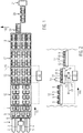
- FIG. 1 a food production line is shown in plan view, wherein in a food slicing machine 1 several food products 2, 3, 4, 5 are cut by means of a rotating knife 6.
- the food products 2, 3, 4, 5 may be, for example, cheese, sausage or ham.
- the food products 2, 4 differ from the food products 3, 5.
- the invention can also be used for identical food products 2, 3, 4, 5 in the adjacent, parallel tracks.
- the first food products may be 2, 4 ham bars, and the second food products 3, 5 sausage bars.
- different cheeses can be sliced, and the food portion then combined.
- the food portions are produced by stacking food slices on a portion tray 8. Due to the different food products 2, 4 and 3, 5, food portions 9, 10 of different types are alternately formed, namely first food portions 9 and second food portions 10.
- four tracks of food portions 9, 10 are provided next to each other, each track first only has either first or second food portions 9, 10.
- Each set of food portions 9, 10 has four food portions, each with two first food portions 9 and two second food portions 10.
- the portion tray 8 is in particular a conveyor, such as a conveyor belt, the finished food portions 9, 10 in a conveying direction 100 of the production line on can promote.
- the food portions are then moved to an alignment and grouping device 11, in which the food portions can be moved relative to each other.
- individually controllable conveying means are provided, with different conveying speeds in the conveying direction 100 of the production line or in the transverse direction 102.
- the food portions 9, 10 are aligned by the aligning and grouping device 11 so that they can be conveyed to a first conveying means 12 , which is a formatting and buffering device.
- the food portions 9, 10 are then arranged in a desired format arrangement, that is arranged in a predetermined arrangement to each other.
- the food portion rows in the transverse direction 102 each consist alternately of first and second food portions 9, 10 and the respective tracks in the conveying direction 100 always from a type of food portions 9 or 10.
- the format arrangement of the food portions 9, 10 is then promoted in the conveying direction 100 of the production line on a support surface 14 of a rotating device 13 which can be rotated about a vertical axis 15.
- FIG. 1 the storage surface 14 is already shown in the rotational position.
- the food portions 9, 10 arranged thereon can be rotated together in the format set about the vertical axis 15, in the present embodiment by 90 °.
- the first and second food portions 9, 10 are now alternately arranged in a track, as shown in Figurl.
- the storage surface 14 is provided by a second conveyor 16, which is in particular a conveyor belt.
- the conveying direction 101 of the second conveying means is aligned in the transverse direction 102 to the conveying direction 100 of the production line.
- the conveying direction 101 of the second conveyor 16 is aligned in the direction of the conveying direction 100 of the production line.
- the food portions 9, 10 rotated by the rotating device 13 while maintaining their format arrangement are then further conveyed by the second conveying means 16 to a third conveying means 17, which constitutes a further buffer device, in particular in the form of a conveyor belt.
- the third conveyor 17 is adjoined by a separating device 18 and an assembly device 19, which consists for example of a conveyor belt which can be displaced in the transverse direction 102, and makes it possible for the food portions 9, 10 of the various tracks to be brought together on a single-track track 20 of a packaging machine 21.
- a first and second food portion 9, 10 is arranged on the single-track 20, so that they can be packaged together.
- FIG. 2 The embodiment according to the invention of the device for handling food portions is made FIG. 1 shown in side view, wherein the device comprises the first conveyor 12, the rotating device 13 with the second conveyor 16 and a third conveyor 17, each of which can be controlled by a central controller 22. Furthermore, it is also possible that the controller 22 and the other components of the production line FIG. 1 centrally controls.
- the first conveying means 12 and the third conveying means 17 are each arranged in a stationary manner.
- the second conveying means 16 of the rotating device 13 can be moved along the conveying direction 100 of the production line on a linear guide 23.
- a carriage 24 is provided, which can be moved by a controlled by the controller 22 drive on the linear guide 23.
- the second conveying means 16 is arranged rotatably on the carriage 24 about the vertical axis 15, wherein a drive controlled by the controller 22 is likewise provided for the rotational movement.
- the top and bottom surface 14 of the second conveyor 16 is located just below the bottom of the first conveyor 12, so that the second conveyor 16 can be moved under the first conveyor 12.
- the carriage 24 with the same or substantially the same conveying speed as the first conveyor 12 in the conveying direction 100 of the production line along the linear guide 23, so the food portions 9, 10 can be stored from above on the support surface 14 of the rotator 13 without the second conveyor 16 would have to perform a conveying movement.
- the support surface 14 and thus the second conveyor 16 can be arranged in a starting position, in which the conveying direction 100 of the production line is not aligned with the conveying direction 101 of the second conveyor 16, but is rotated at an angle thereto.
- the second conveying means 16 is rotated in the starting position so that its conveying direction 101 is aligned in the transverse direction 102.
- the second conveyor 16 is rotated about the vertical axis 15, so that the conveying direction 101 of the second conveyor 16 is aligned with the conveying direction of the production line 100, and thus also with the conveying direction of the third conveying means 17.
- the carriage 24 with the vertical axis 15 represents a arranged under the support surface 14 movement means with which the support surface 14 can be rotated with the food portions 9, 10.
- the second conveyor 16 is located just above the third conveyor 17 so that a rotation is made possible without the conveyor 16, 17 come into contact with each other.
- a height adjustment for the second conveyor 16 may be provided, which may also be controlled by the central controller 22, so that the second conveyor 16 can be brought to the same level with the third conveyor 17 when it is in the rotational position, so that the Food portions 9, 10 at the same level and flush from the second conveyor 16 can be promoted to the third conveyor 17.
- the rotator 13 is designed for rotating an entire format arrangement of food portions and integrated into the production line.
- the food portions 9, 10 from different tracks can consequently are combined in several tracks, and this is particularly advantageous in the production of so-called Twinstacks, ie combinations of two food portions 9, 10, which are packaged together in a tubular bag packaging machine in a tubular bag.
- the merging device 19 may alternatively also be a plate distributor in which the food portions 9, 10 of several tracks can be brought together on a track by means of transversely displaceable plate elements.
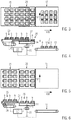
- FIGS. 3 to 8 is a second embodiment of the invention is shown, which is characterized primarily by the fact that the first conveyor 25 is designed as a withdrawal belt, and that in the rotator 26, a rotation and height adjustment of the second conveyor 16 can be done.
- downstream withdrawal roller 27 of the first conveyor 25 is disposed over the support surface 14 of the second conveyor 16.
- the front retracting roller 27 is continuously withdrawn against the conveying direction 100, wherein the tension of the withdrawal tape is maintained by a corresponding movement of the compensating roller 28.
- the retraction roller 27 and the balancing roller 28 are arranged on a displaceable support. The movement of the withdrawal roller 27 can be effected by a drive which moves the carrier linearly.
- the conveyor belt of the first conveyor 24 is moved so that the food portions 9, 10 arranged thereon substantially remain in place while the withdrawal belt is pulled away below them, so that they on the directly below arranged support surface 14 of the second conveyor 16 of the rotating device 26 come to rest.
- FIGS. 5 and 6 The fully retracted state of the withdrawal tape is then in FIGS. 5 and 6 It can be seen that a complete format set of food products 9, 10 rests on the storage surface 14. Now the storage surface 14 is rotated by means of the rotating device 26 from the starting position to the rotational position, so that the conveying direction 101 of the second conveyor 16 is aligned with the conveying direction of the third conveyor 17, which corresponds in particular to the conveying direction 100 of the production line. Before, during or after the rotation of the second conveying means 16, the second conveying means 16 is moved vertically by the height adjustment device 29, so that contact between the conveying means 25, 16 and 17 with each other and the food portions 9, 10 arranged thereon is prevented.
- the second conveying means 16 may be arranged slightly above the third conveying means 17, so that a rotation is possible and yet the food portions 9, 10 can be promoted from the second conveying means 16 to the third conveying means 17 without substantial step.
- the compensating roller is always moved exactly with the retraction roller 27, that the belt tension of the first conveyor 24 is maintained.
- a controller 22 is provided, the respective drives of the first conveyor 25, the adjustment of the withdrawal roller 27 and balancing roller 28, the second conveyor 16, the rotation of the second conveyor 16 about the vertical axis 15, the height adjustment 29 and of the third conveyor 17 can drive targeted.
- the entire format of food portions 9, 10 of the first conveyor 25 by means of driving the conveyor belt of the first conveyor 25 and retraction of the retraction roller 27 can be moved to the support surface 14 of the second conveyor 16.
- the second conveyor 16 is at the moment of receiving the food portions transverse to the conveying direction 100 of the production line and is at a slightly lower level than the upstream first conveyor 25.
- the subsequent third conveyor 17 which is designed to buffer at least one format arrangement of food portions 9, 10.
- the position of the vertical rotation axis 15 remains unchanged, but the height level of the second conveyor 17 can be changed via the height adjustment 29 so as not to come in contact with the belt edges of the downstream or upstream conveyor 17, 25 when rotating.
- the turning means 26 can either slightly raise or lower the second conveying means 16 when turning by means of the height adjustment 29 and moved back to the previous position after twisting.
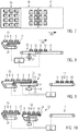
- FIG. 9 shows a third embodiment in which the rotating means 30 is configured substantially as in the first embodiment, that is, that the rotating means 30 has a linear guide 31 in the conveying direction 100 of the production line. Then, in turn, a carriage 24 can be moved, on which the second conveying means 16 is provided rotatable about the vertical axis 15. As the first conveying means 25, a withdrawal belt is provided with which the food portions 9, 10 can be deposited on the second conveyor 16 in a format arrangement. Furthermore, in the third embodiment according to FIG. 9 the third conveying means 17 are arranged at the same height as the second conveying means 16, and contact between the conveying means with each other or with the food portions 9, 10 can be prevented by the longitudinal adjustment of the second conveying means 16.
- the height level of the tray 14 can be maintained and only the vertical axis of rotation 15 is moved in the conveying direction 100 of the production line.
- the first conveyor 25 is also according to the fourth embodiment of the invention FIG. 10 designed as a withdrawal band.
- the second conveyor 33 of the rotary device 32 is now configured as a withdrawal belt.
- the withdrawal roller 34 can in the in FIG. 10 shown rotated position while the rotator 32, the second conveyor 33 rotates. Thereafter, the retraction roller 34 can be extended so that it allows a flush belt transition between the second conveyor 33 and the third conveyor 17.
- a rotating device 35 is provided, which is characterized by an eccentric, vertical axis of rotation 36 on the second conveyor 16.
- food portions 9, 10 are applied to the support surface 14 of the second conveyor 16 by means of a withdrawal belt 25 formed as a withdrawal belt, while this is arranged in a starting position in which its conveying direction 101 is at an angle to the conveying direction 100 of the production line.
- the angle is advantageously 90 °.
- the second conveyor 16 is rotated about the vertical axis of rotation 36 until the second conveyor 16 adjacent to the third conveyor 17, and the conveying direction 101 of the second conveyor 16 with the conveying direction 100 of the third conveyor 17 is aligned , Then the food portions 9, 10 can be further promoted from the second conveyor 16 to the third conveyor 17.
- the rotation axis 36 is spatially fixed. But it can also be provided that the axis of rotation 36 in the conveying direction 100 of the production line linear or even after a predetermined path, such as a web contour, is movable. This allows, for example, that the storage surface 14 can be moved under the first conveyor 12, which is thus not formed as a withdrawal belt, but as a normal conveyor belt.
- FIGS. 13 to 15 A sixth embodiment of the invention is disclosed in FIGS. 13 to 15 shown.
- the sixth embodiment is characterized in that the rotary device 37 is realized by a movement device arranged below the support surface 14.
- this is a slide guide 38 with the second conveyor 16 from the in FIG. 13 represented starting position in the in FIG. 15 shown twisted position can be moved.
- the second conveying means 16 is aligned so that its conveying direction 101 corresponds to the conveying direction 100 of the production line.
- the food portions 9, 10 can be conveyed directly from the first conveyor 12 to the second conveyor 33 in a simple manner.
- the second conveying means 33 is designed in particular as a withdrawal conveyor belt, as in FIG FIG. 14 shown. If a complete format set is arranged on the second conveying means 33, the second conveying means 33 is moved along the link guide 38, so that it is arranged in the rotational position next to the third conveying means 17.
- the retraction roller 39 of the second conveyor 33 is brought into the extended position on the third conveyor 17 and slowly withdrawn while conveying the individual food portions 9, 10 from the second conveyor 33 to the third conveyor.
- the food portions 9, 10 promoted in the format set on the third conveyor 17.
- the entire format set is rotated by 90 ° by means of the rotator 37.
- the first conveying means 12 may be at the same height as the second conveying means 33, which enables an advantageous belt transition of the food portions 9, 10 from the first conveying means 12 to the second conveying means 33.
- an integrated robot an articulated arm kinematics or a pneumatically or hydraulically controlled cantilever can be provided under the second conveyor 33.
- the movement device is designed to swivel out the bearing surface 14 and to move it over the third conveying device 17 in regions.
- an additional height adjustment at the pivot point of the rotary device 37 may be provided, for example via a cylinder, a worm or a spindle.
- it can be provided to arrange the movement device obliquely, including the axis of rotation to compensate for differences in height.
- An optional pivot mechanism may be provided to adjust the support surface 14 to a slight extent obliquely.
- the second conveyor 33 is actuated to deliver the food portions 9, 10 of the support surface 14 to the third conveyor 17, which is designed to buffer at least one format arrangement of food portions 9, 10 is.
- the second conveyor may also be an ordinary conveyor belt and not a withdrawal belt.
- the moving means of the turning means is designed so that the second conveying means can be moved via the third conveying means, while the food portions are discharged from the second conveying means to the third conveying means.
- the rotator 37 may be integrated in a modular cassette 56.
- the cassette 56 has the rotating device 37 including the second conveyor 33 and the slide guide 38 and their drives.
- the cassette 56 thus forms a self-sufficient module that can be integrated into the production line as needed.
- the cassette 56 can be replaced with a simple cassette with a continuous conveyor belt when no turning function is needed.
- a rotating device 40 comprises a gantry robot 41, in which a carriage 42 can be moved at least along a linear guide 43.
- the linear guide 43 extends in the conveying direction 100 of the production line.
- the second conveyor 16 is rotatably suspended about a vertical axis 44.
- the second conveyor 16 can now, as in FIG. 14 shown to be aligned so that his The conveying direction 101 is transverse to the conveying direction 100 of the production line.
- the second conveyor 16 is then moved by means of the gantry robot 41 under the first conveyor 12.
- the food portions 9, 10 are arranged on the second conveying means 16, in that at the same time and at the same speed, the belt of the first conveying means 12 and the carriage 42 are moved in the conveying direction 100.
- the second conveying means 16 After the format arrangement of food portions 9, 10 is arranged on the second conveyor 16, this is further moved in the conveying direction 100 and thereby rotated until its conveying direction 101 with the conveying direction 100 of the production line, which corresponds to the conveying direction of the third conveyor 17, aligned. As soon as the second conveying means 16 has moved up flush to the third conveying means 17, the entire twisted format arrangement can be moved on to the third conveying means 17.
- another robot can be provided, which is arranged above the production line and can implement a complete format, including the support belt.
- the robot is in each case designed so that it can grasp and move the bearing surface 14 of the second conveying means 16.
- the robot is fastened to a frame 45 above the second conveying means 16.
- the robot is directly attached to the frame with its supporting structure.
- the robot can be modular and removable if no turning station in the line pass is needed.
- the robot and its supporting structure can have approximately the dimensions of the rotating station.
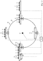
- FIG. 17 an eighth embodiment of the invention is shown in which the rotating means 46 has a rotating about a horizontal axis 47 rotary wheel 48.
- a plurality of second conveyor 16 are distributed around the circumference, in such a way that they can be rotated about a vertical axis 15, respectively.
- a second conveyor 16 can now be arranged in the initial position at the first conveyor 25, which is designed as a withdrawal belt.
- the rotary wheel 48 is preferably arranged only on one side of the production line, and the second conveying means 16 are arranged on cantilevers. This allows the second conveyor 16 to be easily detached to one side. Alternatively, however, a two-sided arrangement of rotary wheels is possible, which are connected to trusses on which the second conveyor 16 are arranged.
- the turning device advantageously comprises at least one driven conveyor belt for dispensing and / or receiving the food portions 9, 10 in a format arrangement.
- a continuous wide conveyor belt or individually driven tracks are provided on the rotating device.
- the rotary device can be configured as a modular rotary cassette, which has all the necessary drives and thus forms a self-sufficient module that can be integrated into the production line as needed.
- the rotary cassette can be exchanged for a simple cassette with continuous conveyor belt, if no rotary function is needed.
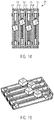
- FIGS. 18 and 19 Another embodiment of a rotator 49 is shown in FIGS. 18 and 19 shown.
- This rotating device has a plurality of parallel tracks 50, 51, 52, 53, each having a first and second conveyor belt 54, 55.
- the conveyor belts 54, 55 are each provided with separately controllable drives, so that they can be operated at different speeds. This makes it possible to rotate food portions 9, 10, which are arranged in the respective tracks.
- the food portions 9, 10 are preferably twisted with some longitudinal displacement, so that their corners do not touch when turning.
- all food portions of a format arrangement can be jointly or simultaneously rotated at individual points on a rotating device 49.
- each food portion is lifted with its respective associated turntable slightly from the support surface of the second conveyor, then rotated and then dropped off again on the support surface.
- the support surface may consist of two parallel conveyor belts.
- the turntables are preferably coupled together, and are guided in particular in an associated backdrop, so that the same movement is performed by several turntables, and equal to several food portions twisted can be.
- the coupling can be done in particular by means of a belt drive, via a lever arrangement or coupling rods.
- no band gap arises because no displacement of the rotary device in the conveying direction is necessary.
- the offset shown when turning on adjacent tracks arises because in each case the slotted guide for adjacent turntable is installed with some longitudinal displacement.
- the invention provides an efficient method and an advantageous device for producing combinations of two portions of food portions, which can subsequently be packaged together in a tubular bag in a tubular bag packaging machine.
- the format arrangement of the food portions 9, 10 can be completely rotated in the production line, wherein the rotation function is integrated into the production line.
- the format formation and exact alignment of food portions to each other can be done before the turning device, since the rotating device allows maintaining the format arrangement. Thus, after the turning device, only one buffering and, if appropriate, a singling is connected downstream, but no alignment and grouping have to take place any longer.
Landscapes
- Engineering & Computer Science (AREA)
- Mechanical Engineering (AREA)
- Life Sciences & Earth Sciences (AREA)
- Forests & Forestry (AREA)
- Attitude Control For Articles On Conveyors (AREA)
Applications Claiming Priority (1)
| Application Number | Priority Date | Filing Date | Title |
|---|---|---|---|
| DE102017223709.0A DE102017223709A1 (de) | 2017-12-22 | 2017-12-22 | Vorrichtung und Verfahren zur Handhabung von Lebensmittelportionen mit einer Dreheinrichtung |
Publications (1)
| Publication Number | Publication Date |
|---|---|
| EP3502017A1 true EP3502017A1 (fr) | 2019-06-26 |
Family
ID=64901881
Family Applications (1)
| Application Number | Title | Priority Date | Filing Date |
|---|---|---|---|
| EP18215543.2A Withdrawn EP3502017A1 (fr) | 2017-12-22 | 2018-12-21 | Dispositif et procédé de manipulation des portions des denrées alimentaires à l'aide d'un agencement rotatif |
Country Status (3)
| Country | Link |
|---|---|
| US (1) | US11027868B2 (fr) |
| EP (1) | EP3502017A1 (fr) |
| DE (1) | DE102017223709A1 (fr) |
Cited By (2)
| Publication number | Priority date | Publication date | Assignee | Title |
|---|---|---|---|---|
| CN113044335A (zh) * | 2021-04-15 | 2021-06-29 | 昆山博一机械制造有限公司 | 用于热加工食品生产的储存装置及后工程生产总线 |
| CN116002343A (zh) * | 2022-12-29 | 2023-04-25 | 唐山因泰智能科技发展有限公司 | 一种防堵塞大粒度范围固体物料用智能排队装置 |
Families Citing this family (4)
| Publication number | Priority date | Publication date | Assignee | Title |
|---|---|---|---|---|
| US20210169120A1 (en) * | 2019-12-04 | 2021-06-10 | West Liberty Foods, L.L.C. | Automated food preparation and packaging systems, methods, and apparatus |
| US20230117987A1 (en) * | 2021-10-20 | 2023-04-20 | Takai Tofu & Soymilk Equipment Co. | Tofu conveying machine |
| DE102023110703A1 (de) * | 2023-04-26 | 2024-10-31 | Multivac Sepp Haggenmüller Se & Co. Kg | Verfahren zum Betreiben einer Verpackungslinie sowie Verpackungslinie |
| GB202307895D0 (en) | 2023-05-26 | 2023-07-12 | Thurne Middleby Ltd | A flap-folding module for a food processing line |
Citations (6)
| Publication number | Priority date | Publication date | Assignee | Title |
|---|---|---|---|---|
| DE2516583A1 (de) * | 1975-04-16 | 1976-10-28 | Waldner Kg H | Beschickungsvorrichtung fuer verpackungsmaschinen |
| GB1576718A (en) * | 1977-10-04 | 1980-10-15 | Metal Box Co Ltd | Conveyor handling systems |
| GB2255762A (en) * | 1991-03-12 | 1992-11-18 | Thurne Eng Co Ltd | A conveyor system. |
| DE19515199A1 (de) * | 1995-04-25 | 1996-10-31 | Alpma Alpenland Masch | Vorrichtung zum Verdrehen von in einem Förderprozeß befindlichen Produkten |
| DE102011105583A1 (de) * | 2011-06-27 | 2012-12-27 | Multivac Sepp Haggenmüller Gmbh & Co. Kg | Verpackungsanlage mit Transporteinrichtung |
| US20170050332A1 (en) * | 2014-04-25 | 2017-02-23 | Weber Maschinenbau Gmbh Breidenbach | Autonomously electromagnetic transport carrier of food portions |
Family Cites Families (9)
| Publication number | Priority date | Publication date | Assignee | Title |
|---|---|---|---|---|
| US4051753A (en) * | 1976-01-30 | 1977-10-04 | Swift & Company | Method and apparatus for assembling items |
| DE3321584A1 (de) * | 1983-06-15 | 1984-12-20 | Guschky & Tönnesmann GmbH & Co KG, 4000 Düsseldorf | Vorrichtung zur bildung von faltschachtel-stapeln |
| FR2672031B1 (fr) * | 1991-01-29 | 1994-10-21 | Cazas Ets | Machine de mise en caisse de doses unitaires. |
| US6520314B1 (en) * | 2002-01-30 | 2003-02-18 | Samuel O. Seiling | Apparatus for arranging packaged bakery goods for shipment |
| US7941990B2 (en) * | 2009-01-06 | 2011-05-17 | Pi-Wi Beheer B.V. | Apparatus for packaging products into a container |
| NL2002912C2 (en) * | 2009-05-20 | 2010-11-23 | Roboxis B V | System, gripping head, and method for displacing products. |
| US8882099B2 (en) * | 2009-08-25 | 2014-11-11 | Lasermax Roll Systems, Inc. | System and method for inline cutting and stacking of sheets for formation of books |
| US20120324840A1 (en) * | 2011-06-27 | 2012-12-27 | Multivac Sepp Haggenmuller Gmbh & Co. Kg | Packaging arrangement with transport device |
| DE102017117292B4 (de) | 2017-07-31 | 2025-12-18 | Dipl.-Ing. Schindler & Wagner Gmbh & Co. Kg | Fördervorrichtung und Verfahren zum Fördern von Produktportionen aus Lebensmittelprodukten sowie Schneidlinie zum Aufschneiden von Lebensmittelprodukten |
-
2017
- 2017-12-22 DE DE102017223709.0A patent/DE102017223709A1/de not_active Withdrawn
-
2018
- 2018-12-21 US US16/230,141 patent/US11027868B2/en not_active Expired - Fee Related
- 2018-12-21 EP EP18215543.2A patent/EP3502017A1/fr not_active Withdrawn
Patent Citations (7)
| Publication number | Priority date | Publication date | Assignee | Title |
|---|---|---|---|---|
| DE2516583A1 (de) * | 1975-04-16 | 1976-10-28 | Waldner Kg H | Beschickungsvorrichtung fuer verpackungsmaschinen |
| GB1576718A (en) * | 1977-10-04 | 1980-10-15 | Metal Box Co Ltd | Conveyor handling systems |
| GB2255762A (en) * | 1991-03-12 | 1992-11-18 | Thurne Eng Co Ltd | A conveyor system. |
| DE19515199A1 (de) * | 1995-04-25 | 1996-10-31 | Alpma Alpenland Masch | Vorrichtung zum Verdrehen von in einem Förderprozeß befindlichen Produkten |
| DE102011105583A1 (de) * | 2011-06-27 | 2012-12-27 | Multivac Sepp Haggenmüller Gmbh & Co. Kg | Verpackungsanlage mit Transporteinrichtung |
| DE102011105583B4 (de) * | 2011-06-27 | 2015-07-16 | Multivac Sepp Haggenmüller Gmbh & Co. Kg | Verpackungsanlage mit Transporteinrichtung |
| US20170050332A1 (en) * | 2014-04-25 | 2017-02-23 | Weber Maschinenbau Gmbh Breidenbach | Autonomously electromagnetic transport carrier of food portions |
Cited By (3)
| Publication number | Priority date | Publication date | Assignee | Title |
|---|---|---|---|---|
| CN113044335A (zh) * | 2021-04-15 | 2021-06-29 | 昆山博一机械制造有限公司 | 用于热加工食品生产的储存装置及后工程生产总线 |
| CN113044335B (zh) * | 2021-04-15 | 2022-10-11 | 昆山博一机械制造有限公司 | 用于热加工食品生产的储存装置及后工程生产总线 |
| CN116002343A (zh) * | 2022-12-29 | 2023-04-25 | 唐山因泰智能科技发展有限公司 | 一种防堵塞大粒度范围固体物料用智能排队装置 |
Also Published As
| Publication number | Publication date |
|---|---|
| US20190193884A1 (en) | 2019-06-27 |
| DE102017223709A1 (de) | 2019-06-27 |
| US11027868B2 (en) | 2021-06-08 |
Similar Documents
| Publication | Publication Date | Title |
|---|---|---|
| EP2500296B1 (fr) | Dispositif et procédé destinés au groupement de produits en vrac | |
| DE102017223709A1 (de) | Vorrichtung und Verfahren zur Handhabung von Lebensmittelportionen mit einer Dreheinrichtung | |
| DE69618181T2 (de) | Verpackungsmaschine für sammelpackungen | |
| EP3288731B1 (fr) | Dispositif de découpe | |
| EP2420364B1 (fr) | Equipement destiné à compléter une portion lors de la coupe sur plusieurs voies | |
| EP2799348B1 (fr) | Procédé de regroupement d'articles en un faisceau d'articles et dispositif de regroupement et machine d'emballage doté d'un tel dispositif | |
| DE102011075439A1 (de) | Verfahren und Vorrichtung zum Verpacken streifenförmiger Gegenstände, insbesondere Kaugummistreifen | |
| EP2139776A2 (fr) | Dispositif et procédé pour la manipulation d'objets plats, en particulier de couches | |
| EP2826735A1 (fr) | Section ajustable de stockage tampon d'un dispositif de convoyage et procédé de stockage intermédiaire d'articles | |
| EP4284736A1 (fr) | Système de transport pour transporter des marchandises à transporter | |
| EP3003874B1 (fr) | Procédé et dispositif permettant de produire des unités d'emballage dans une ensacheuse verticale | |
| DE69812217T2 (de) | Maschine zum Stapeln von Bögen in Bündeln | |
| EP2955135A1 (fr) | Système de transport de piles de marchandises composées de palettes comprenant des marchandises empilées et procédé de transport de piles de marchandises composées de palettes comprenant des marchandises empilées | |
| DE69405351T2 (de) | Maschine zum Verpacken von Gegenständen | |
| DE102017203588B4 (de) | Vorrichtung zum Umgang mit Artikeln sowie Verfahren zum Tauschen mindestens eines Transportmoduls und wenigstens eines Arbeitsmoduls der Vorrichtung | |
| DE102013207401A1 (de) | Vorrichtung und Verfahren zum Aufschneiden von Lebensmittelprodukten | |
| EP3068713B1 (fr) | Procédé et dispositif de transport et de regroupement de produits en morceaux | |
| EP0591099B1 (fr) | Procédé et dispositif pour fabriquer des piles de produits en papier liées | |
| EP2133271A1 (fr) | Dispositif et procédé de transmission de marchandises sur un système de transport de marchandises ou sur un dispositif de stockage | |
| EP2133293B1 (fr) | Dispositif de transmission de marchandises sur un système de transport de marchandises ou sur un dispositif de stockage | |
| EP0799780A2 (fr) | Dispositif de palettisation pour ramettes de papier | |
| EP3583056A1 (fr) | Dispositif et procédé de distribution flexible d'emballages | |
| DE1228503B (de) | Ablagevorrichtung fuer Schlauchziehmaschinen | |
| DE2808948A1 (de) | Vorrichtung zum aufeinanderschichten von lagen aus papierbogen | |
| DE102019112812A1 (de) | Portioniervorrichtung zum Bilden von Portionsstapeln, die jeweils mindestens eine mittels einer ein Messer aufweisenden Schneideinrichtung von einem Produktlaib abgetrennte Produktscheibe umfassen |
Legal Events
| Date | Code | Title | Description |
|---|---|---|---|
| PUAI | Public reference made under article 153(3) epc to a published international application that has entered the european phase |
Free format text: ORIGINAL CODE: 0009012 |
|
| STAA | Information on the status of an ep patent application or granted ep patent |
Free format text: STATUS: THE APPLICATION HAS BEEN PUBLISHED |
|
| AK | Designated contracting states |
Kind code of ref document: A1 Designated state(s): AL AT BE BG CH CY CZ DE DK EE ES FI FR GB GR HR HU IE IS IT LI LT LU LV MC MK MT NL NO PL PT RO RS SE SI SK SM TR |
|
| AX | Request for extension of the european patent |
Extension state: BA ME |
|
| STAA | Information on the status of an ep patent application or granted ep patent |
Free format text: STATUS: REQUEST FOR EXAMINATION WAS MADE |
|
| 17P | Request for examination filed |
Effective date: 20191212 |
|
| RBV | Designated contracting states (corrected) |
Designated state(s): AL AT BE BG CH CY CZ DE DK EE ES FI FR GB GR HR HU IE IS IT LI LT LU LV MC MK MT NL NO PL PT RO RS SE SI SK SM TR |
|
| STAA | Information on the status of an ep patent application or granted ep patent |
Free format text: STATUS: EXAMINATION IS IN PROGRESS |
|
| 17Q | First examination report despatched |
Effective date: 20220712 |
|
| P01 | Opt-out of the competence of the unified patent court (upc) registered |
Effective date: 20230523 |
|
| RAP3 | Party data changed (applicant data changed or rights of an application transferred) |
Owner name: WEBER FOOD TECHNOLOGY GMBH |
|
| STAA | Information on the status of an ep patent application or granted ep patent |
Free format text: STATUS: THE APPLICATION IS DEEMED TO BE WITHDRAWN |
|
| 18D | Application deemed to be withdrawn |
Effective date: 20250701 |