EP3502396B1 - Appareil d'actionnement pour barrières coulissantes - Google Patents
Appareil d'actionnement pour barrières coulissantes Download PDFInfo
- Publication number
- EP3502396B1 EP3502396B1 EP18214123.4A EP18214123A EP3502396B1 EP 3502396 B1 EP3502396 B1 EP 3502396B1 EP 18214123 A EP18214123 A EP 18214123A EP 3502396 B1 EP3502396 B1 EP 3502396B1
- Authority
- EP
- European Patent Office
- Prior art keywords
- rotation
- actuator apparatus
- locking member
- shaft
- motor
- Prior art date
- Legal status (The legal status is an assumption and is not a legal conclusion. Google has not performed a legal analysis and makes no representation as to the accuracy of the status listed.)
- Active
Links
Images



Classifications
-
- E—FIXED CONSTRUCTIONS
- E05—LOCKS; KEYS; WINDOW OR DOOR FITTINGS; SAFES
- E05F—DEVICES FOR MOVING WINGS INTO OPEN OR CLOSED POSITION; CHECKS FOR WINGS; WING FITTINGS NOT OTHERWISE PROVIDED FOR, CONCERNED WITH THE FUNCTIONING OF THE WING
- E05F15/00—Power-operated mechanisms for wings
- E05F15/60—Power-operated mechanisms for wings using electrical actuators
- E05F15/603—Power-operated mechanisms for wings using electrical actuators using rotary electromotors
- E05F15/632—Power-operated mechanisms for wings using electrical actuators using rotary electromotors for horizontally-sliding wings
- E05F15/635—Power-operated mechanisms for wings using electrical actuators using rotary electromotors for horizontally-sliding wings operated by push-pull mechanisms, e.g. flexible or rigid rack-and-pinion arrangements
-
- E—FIXED CONSTRUCTIONS
- E05—LOCKS; KEYS; WINDOW OR DOOR FITTINGS; SAFES
- E05Y—INDEXING SCHEME ASSOCIATED WITH SUBCLASSES E05D AND E05F, RELATING TO CONSTRUCTION ELEMENTS, ELECTRIC CONTROL, POWER SUPPLY, POWER SIGNAL OR TRANSMISSION, USER INTERFACES, MOUNTING OR COUPLING, DETAILS, ACCESSORIES, AUXILIARY OPERATIONS NOT OTHERWISE PROVIDED FOR, APPLICATION THEREOF
- E05Y2201/00—Constructional elements; Accessories therefor
- E05Y2201/20—Brakes; Disengaging means; Holders; Stops; Valves; Accessories therefor
- E05Y2201/218—Holders
- E05Y2201/22—Locks
-
- E—FIXED CONSTRUCTIONS
- E05—LOCKS; KEYS; WINDOW OR DOOR FITTINGS; SAFES
- E05Y—INDEXING SCHEME ASSOCIATED WITH SUBCLASSES E05D AND E05F, RELATING TO CONSTRUCTION ELEMENTS, ELECTRIC CONTROL, POWER SUPPLY, POWER SIGNAL OR TRANSMISSION, USER INTERFACES, MOUNTING OR COUPLING, DETAILS, ACCESSORIES, AUXILIARY OPERATIONS NOT OTHERWISE PROVIDED FOR, APPLICATION THEREOF
- E05Y2201/00—Constructional elements; Accessories therefor
- E05Y2201/20—Brakes; Disengaging means; Holders; Stops; Valves; Accessories therefor
- E05Y2201/23—Actuation thereof
- E05Y2201/246—Actuation thereof by auxiliary motors, magnets, springs or weights
-
- E—FIXED CONSTRUCTIONS
- E05—LOCKS; KEYS; WINDOW OR DOOR FITTINGS; SAFES
- E05Y—INDEXING SCHEME ASSOCIATED WITH SUBCLASSES E05D AND E05F, RELATING TO CONSTRUCTION ELEMENTS, ELECTRIC CONTROL, POWER SUPPLY, POWER SIGNAL OR TRANSMISSION, USER INTERFACES, MOUNTING OR COUPLING, DETAILS, ACCESSORIES, AUXILIARY OPERATIONS NOT OTHERWISE PROVIDED FOR, APPLICATION THEREOF
- E05Y2201/00—Constructional elements; Accessories therefor
- E05Y2201/20—Brakes; Disengaging means; Holders; Stops; Valves; Accessories therefor
- E05Y2201/252—Type of friction
- E05Y2201/26—Mechanical friction
-
- E—FIXED CONSTRUCTIONS
- E05—LOCKS; KEYS; WINDOW OR DOOR FITTINGS; SAFES
- E05Y—INDEXING SCHEME ASSOCIATED WITH SUBCLASSES E05D AND E05F, RELATING TO CONSTRUCTION ELEMENTS, ELECTRIC CONTROL, POWER SUPPLY, POWER SIGNAL OR TRANSMISSION, USER INTERFACES, MOUNTING OR COUPLING, DETAILS, ACCESSORIES, AUXILIARY OPERATIONS NOT OTHERWISE PROVIDED FOR, APPLICATION THEREOF
- E05Y2201/00—Constructional elements; Accessories therefor
- E05Y2201/60—Suspension or transmission members; Accessories therefor
- E05Y2201/622—Suspension or transmission members elements
- E05Y2201/71—Toothed gearing
- E05Y2201/716—Pinions
-
- E—FIXED CONSTRUCTIONS
- E05—LOCKS; KEYS; WINDOW OR DOOR FITTINGS; SAFES
- E05Y—INDEXING SCHEME ASSOCIATED WITH SUBCLASSES E05D AND E05F, RELATING TO CONSTRUCTION ELEMENTS, ELECTRIC CONTROL, POWER SUPPLY, POWER SIGNAL OR TRANSMISSION, USER INTERFACES, MOUNTING OR COUPLING, DETAILS, ACCESSORIES, AUXILIARY OPERATIONS NOT OTHERWISE PROVIDED FOR, APPLICATION THEREOF
- E05Y2201/00—Constructional elements; Accessories therefor
- E05Y2201/60—Suspension or transmission members; Accessories therefor
- E05Y2201/622—Suspension or transmission members elements
- E05Y2201/71—Toothed gearing
- E05Y2201/722—Racks
-
- E—FIXED CONSTRUCTIONS
- E05—LOCKS; KEYS; WINDOW OR DOOR FITTINGS; SAFES
- E05Y—INDEXING SCHEME ASSOCIATED WITH SUBCLASSES E05D AND E05F, RELATING TO CONSTRUCTION ELEMENTS, ELECTRIC CONTROL, POWER SUPPLY, POWER SIGNAL OR TRANSMISSION, USER INTERFACES, MOUNTING OR COUPLING, DETAILS, ACCESSORIES, AUXILIARY OPERATIONS NOT OTHERWISE PROVIDED FOR, APPLICATION THEREOF
- E05Y2900/00—Application of doors, windows, wings or fittings thereof
- E05Y2900/40—Application of doors, windows, wings or fittings thereof for gates
Definitions
- the present invention relates to an actuator apparatus for sliding barriers such as doors, gates, and the like.
- actuators for sliding barriers comprising an electric motor and a reduction gear, which has the input shaft coupled with the output shaft of the electric motor and the output shaft provided with a pinion.
- the electric motor and the reducer constitute a single unit (geared motor), which is connected to a specific base, usually made out of concrete, arranged near the sliding barrier to be moved, so that the output pinion can engage a rack integral with the barrier itself.
- the need to couple the motor to a gearbox is linked to the fact that a normal electric motor fed by the network and designed to drive a sliding barrier has a rotation speed that is too high and unable to directly drive a pinion coupled to the barrier rack, and at the same time, given its necessarily limited size for reasons of space, generates a low torque, sometimes insufficient to move the barrier.
- the gearbox has the function of reducing the speed of rotation of the motor and increasing the torque at the same time, thus allowing a small electric motor powered by the network and suitable to perform a function that without the gearbox would hardly be able to perform.
- An actuator of this type is, for example, described in US 4887205 in which the pinion associated with the output shaft of the engine is coupled to a series of gears for reducing the rotation speed of the engine; in particular, then, the last gear engages the links of a chain which is integral with the barrier to be moved.
- the gearbox also performs the important function of making the geared motor unit irreversible, since the high reduction ratio of the motor means that any attempt to rotate the pinion by direct thrust on the barrier is prevented by the nature of the gear unit itself. Consequently, if the motor is not powered, the movement of the barrier due to direct stress on the same is prevented, and therefore a forced opening of the barrier is prevented.
- EP1770238 discloses a mechanical actuator for sliding door panels with a motor and a speed reduction unit that are housed in a buriable casing emerging from the ground by a minimum portion that houses a horizontal shaft on which an operating pinion for the door panel is keyed.
- US 4 887 205 discloses a system for controlling a gate where the gate is driven by a chain which is engaged by a sprocket wheel.
- the sprocket wheel is powered by a motor through an appropriate drive train which includes gears.
- DE 10 2005 051 722 discloses an apparatus for controlling the motion of a swivel gate which comprises an electric drive motor and a reduction gear.
- torque motors are also known, that are engines of particular conception which develop a high torque at low rotation speed and which, thanks to these characteristics, would be directly usable in all those applications requiring this type of performance.
- the object of the invention is to propose an actuator apparatus which allows overcoming the drawbacks and limitations present in traditional solutions.
- Another object of the invention is to propose an actuator apparatus which allows to actuate a sliding barrier with a torque motor, which, with respect to a traditional actuator comprising a traditional electric motor and a reduction gear, is of simpler embodiment.
- Another object of the invention is to propose a more compact actuator apparatus.
- Another object of the invention is to propose a more economical actuator apparatus.
- Another object of the invention is to propose an actuator apparatus for actuating a sliding barrier which, with the same barrier, results in less absorption of electrical energy.
- Another object of the invention is to propose an actuator apparatus for actuating a sliding barrier with fewer components, to avoid or limit failures and malfunctions.
- Another object of the invention is to propose an actuator apparatus for actuating a sliding barrier which ensures a mechanical locking of the barrier in any intermediate position between its extreme positions.
- Another object of the invention is to propose an actuator which is perfectly in line with the safety requirements imposed by the sector legislation.
- Another object of the invention is to propose an actuator that improves and/or is alternative to traditional ones.
- Another object of the invention is to propose an actuator apparatus that is simple, quick and inexpensive to install.
- Another object of the invention is to propose a sliding barrier which is provided with an actuator apparatus which is simple to manufacture, has a small size and is not expensive to manufacture and install.
- the actuator apparatus 1 for a sliding barrier comprises an electric motor which is a torque motor 2 configured to cause the rotation of its output motor shaft 10.
- the torque motor 2 is brushless and synchronous.
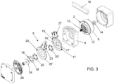
- the actuator apparatus 1 comprises a housing 4 which houses the stator 6 of the motor 2 and supports, by means of bearings 8, the motor shaft 10, to which the rotor 12 of the motor 2 is integral.
- the torque motor 2 comprises only two functional elements: the stator 6 and the rotor 12, which is coupled directly to the shaft 10 to be rotated.
- the motor 2 is intended to be connected and managed by a control and command unit.
- said control and command unit comprises at least one electronic board.
- the maximum rotation speed of the torque motor 2 under normal operating conditions is not higher than 600 revolutions per minute.
- a pinion 14 is fitted together with the shaft 10, or preferably they are made of a single body, intended to be coupled with a linear gear, preferably a rack 16 (but it could also be a chain), which is applied to the sliding barrier to be moved, not represented.
- the output of the motor shaft 10 of the motor 2 is provided with a pinion 14 which directly engages - that is, without the interposition of a transmission unit, a gear or other gears - the linear gear 16, preferably a rack, which is integral with the sliding barrier to be moved.
- the pinion 14 has a number of teeth comprised between eight and seventeen.
- the pinion 14 has a number of teeth not greater than seventeen, preferably not more than twelve and even more preferably not more than eight.
- the actuator apparatus 1 also comprises a locking device comprising:
- the bolt engagement member 26 is mounted on the housing of the torque motor 2.
- Said locking member 22 comprises a toothed wheel 22' which is mounted neutral on the shaft 10 of the torque motor 2.
- the locking member 22 comprises a toothed wheel 22', in which at least one tooth is designed to be engaged by said bolt engagement member 26, when said torque motor 2 is not supplied; said bolt engagement member 26 is associated with an electromagnetic actuator 23 of the monostable type, which brings it in a disengaged condition from said toothed wheel 22' when it is powered and allows that the elastic reaction of at least one elastic element, preferably a spring 28, brings it in an engaged condition when it is not powered.
- Said damping mechanism 5 comprises at least one body 18 or 19 which is integral in rotation with the output shaft 10 and which is kept in contact with the locking member 22.
- Said damping mechanism 5 comprises at least one friction element 20 or 20' which is interposed between the locking member 22 and said body 18 or 19 which is integral with rotation with the output shaft 10.
- said damping mechanism 5 comprises a pair of jaws 18', 19' that are integral with rotation to the output shaft 10 and placed on both sides of said toothed wheel 22' and held elastically clamped thereto.
- each jaw 18', 19' is provided on the side facing said toothed wheel 22' of a friction element 20, 20'.
- the actuator apparatus 1 comprises a further locking member 17 integral with rotation to the output shaft 10 of the torque motor 2 and associated with a further engagement member 25 which is moved by a further electromagnetic actuator 27 which can be operated between one engagement condition of said further locking member 17, when said motor 2 is stationary, and a condition for disengaging said further locking member 17 when said motor 2 is supplied.
- the switching of said further electromagnetic actuator 27, being controlled by said control and command unit coincides with the passage of motor 2 from the condition supplied to the unpowered condition and vice versa.
- said further locking member 17 is constituted by a body 19 of said damping mechanism 5 which is integral in rotation with the output shaft 10 and which is kept in contact with the first locking member 22.
- said bodies of the damping mechanism 5 comprise the annular jaw 18' and a further toothed wheel 17' which, preferably, acts as a jaw.
- the annular jaw 18' is coupled to the shaft 10 which is configured to be integral in rotation with the shaft itself and also to perform reciprocal movements parallel to the longitudinal direction of development of the rotation axis of the shaft 10.
- said further (second) toothed wheel 17' is fitted together with the shaft 10.
- the first toothed wheel 22' (which defines said locking member), which however it is neutral on the shaft 10.
- both the jaw 18' and the further toothed wheel 17' are associated, on the side facing the first toothed wheel 22', with friction rings 20, 20'.
- the annular jaw 18' is pushed in the direction of the further toothed wheel 17' by one or more springs 24, preferably adjustable in order to regulate the force, with which the interposed first toothed wheel 22' is pressed between the two.
- a first bolt 26 axially movable between the engagement position of the teeth of the further toothed wheel 17' and a position of disengagement therefrom.
- the first bolt engagement member 26 is associated with a monostable electromagnet 23; preferably, for this purpose, a spring 28 is provided, which tends to keep said first bolt 26 in the engagement position of the toothed wheel 22', from which it is removed when its electromagnet 23 is energized by the same supply current of the torque motor 2.
- a second bolt 25 movable axially between the engagement position of the teeth of the further toothed wheel 17' and a position of disengagement therefrom can also be applied to the housing 4 of the motor 2 at the further toothed wheel 17'.
- the second bolt 25 is associated with a first bistable type electromagnet 27.
- both the bolts 26, 25 are provided with a single space engagement tooth delimited by two successive teeth of the respective toothed wheel 22', 17' , but an analogous result could also be obtained with two bolts 26', 25' (see Fig. 8 ), having several teeth simultaneously engaged between several spaces delimited by several successive teeth of the two toothed wheels 22', 17' respectively; on the contrary, advantageously, in this case the engagement between bolts and toothed wheels could be easier, safer and more immediate.
- a gear chain can be associated to the output shaft 10 of the torque motor 2, indicated as a whole with the reference 29, with a revolving gear reduction effect.
- said gears of the chain 29 and/or of the respective rotation shafts are provided with magnetic means 50, 52, 54 cooperating with sensors connected to said control and command unit for processing the signals generated by said sensors for determining the position of said barrier during its travel.
- said magnetic means are constituted by a magnet 50 housed within the output shaft 10 of the pinion 14 and/or by magnets 52 and 54 housed within the rotation shaft 38 and 48 of the respective gears 36 and 46, and having magnetization axis oriented in diametral direction.
- the housing 4 of the torque motor 2 extends into a cylindrical portion 30, which in addition to housing both the toothed wheels 22', 17' also houses the chain of gears 29 having the function of controlling the movement of the sliding barrier.
- this gear chain 29 comprises a first gear 32 integral with the driving shaft 10 and a second gear 34, coupled to the first gear 32 and such that the reduction ratio between the first gear 32 and the second gear 34 is preferably comprised between 1: 3 and 1: 4.
- a smaller third gear 35 is also fitted together, which is coupled to a fourth gear 37, with which it has a coupling ratio preferably comprises between 1: 3 and 1: 4.
- the shaft 38 which supports the fourth gear 37, is fitted together a fifth gear 40, of smaller diameter, which is coupled to a sixth gear 42, of a larger diameter and such that also in this case the coupling ratio between the fifth gear 40 and the sixth gear 42 is preferably between 1: 3 and 1: 5.
- a seventh gear 45 is fitted together with the shaft 44 supporting this sixth gear 42, which in turn is coupled to an eighth gear 46 with a coupling ratio preferably of 1: 3 - 1: 5. Therefore, preferably, the total coupling ratio between the first gear 32 and the eighth gear 46 is preferably between 1:81 and 1: 400.
- a small cylindrical magnet respectively 50, 52, 54 in the shaft 10 of the first gear 32, in the vicinity thereof, in the shaft 38 of the fourth gear 37 and in the shaft 48 of the eighth gear 46 is housed a small cylindrical magnet respectively 50, 52, 54, with the two diametrically opposed N and S polarities, interacting with corresponding sensors connected to the control and command unit (and in particular to a corresponding electronic board) that processes the signals received from them.
- the operation of the actuator apparatus 1 according to the invention is as follows: in normal operating conditions, when the barrier is closed, the second electromagnet 27 maintains the second bolt 25 engaged with the further toothed wheel 17' and the first electromagnet 23, which is not powered, allows the elastic element (preferably spring-loaded) 28 to maintain the first bolt 26 engaged with the second toothed wheel 22'.
- the overall result is that the two bolts 25, 26 keep the motor 2 blocked, preventing the actuation of the barrier by direct manual thrust on it.
- the barrier is to be opened from this condition, it is sufficient to provide a suitable direct or radio command to the system management and control unit, which supplies the two electromagnets 27, 23 and the motor 2.
- the activation of the first electromagnet 27 causes its stable switching in the disengagement position of the second bolt 25 from the further toothed wheel 17'; the activation of the first electromagnet 23 causes the temporary disengagement of the first bolt 26 from the first toothed wheel 22' in contrast with the elastic reaction of the spring 28.
- the power supply of the motor 2 causes the rotation of its pinion 14 which, by engaging directly with the linear gear 16 (preferably a rack), causes the opening movement of the barrier.
- control and command unit itself detects this situation and, in addition to commanding the interruption of the power supply of the motor 2, commands the interruption of the power supply of the first electromagnet 23, so that the elastic reaction of the spring 28 controls the first bolt 26 to engage the teeth of the toothed wheel 22'.
- control and command unit also controls the commutation of the second electromagnet 27, so that the second bolt 25 engages the teeth of the further toothed wheel 17'.
- control and command unit In order to block the barrier in an intermediate position between the extreme ones (i.e. complete closing or full opening), it is planned to give the control and command unit a suitable manual or radio control, so that this acts as if the barrier were in an end position.
- the slowest gear 46 of said gear chain 29 is configured to have a rotation period inferior to the duration of the travel of said barrier between the closed condition and the open condition.
- a complete rotation of the magnet 54 mounted on the shaft 48 of the eighth gear 46 corresponds to the maximum linear design excursion of the sliding barrier and this in order to maintain a biunique correspondence between the linear position of the barrier and the angular position of the magnet 54.
- the magnet 50 of the shaft 10 determines and also controls the rotation of the magnetic field, which causes rotation of the torque motor 2.
- the second bolt 25 would remain disengaged from the further toothed wheel 17' while the first bolt 26 would be immediately activated while the barrier continues to move forward due to inertia, with the risk of damaging the first bolt 26 and/or the toothed wheel 22', from this engaged.
- the damping and friction coupling is provided between the shaft 10 of the motor 2 and the toothed wheel 22', which allows the shaft 10, which is mechanically coupled directly with the linear gear 16 (preferably rack), to continue its rotation by the inertia of the whole moving part, even if the toothed wheel 22 is locked.
- An advantage of the invention consists in the reduced overall dimensions of the actuator apparatus, thanks to the elimination of the reduction gear, which in the traditional actuators entails a significant encumbrance.
- Another advantage of the invention consists in the fact that the elimination of the gear reducer in addition to reducing costs for the elimination of an expensive component, also entails a greater reliability of the actuator 1, since each further component involves further risks of breakdowns or breakages due to its presence.
- the motor is of the torque type and is coupled directly - without the interposition of transmission or reduction units - with the linear gear integral with the sliding barrier and this is particularly advantageous in that it allows completely eliminating all the intermediate gears which, in US 4887205 , are interposed between the pinion secured to the output of the driving shaft and the chain integral with the sliding barrier.
- the engine of US 4887205 is not a torque engine as it requires precisely the presence of a plurality of gears to reduce the rotation speed of the shaft of the engine and to increase the torque at the same time.
- a locking member is provided which acts on the rotation shaft of the torque motor by means of a damping mechanism.
- Another advantage of the invention consists in the possibility of having a secure mechanical locking of the barrier at both ends as well as in any desired intermediate position.
Landscapes
- Connection Of Motors, Electrical Generators, Mechanical Devices, And The Like (AREA)
Claims (12)
- Dispositif actionneur (1) pour barrière coulissante, comprenant un moteur électrique qui est un moteur couple (2) actionné par une unité de contrôle et de commande et configuré pour provoquer la rotation de son arbre de sortie (10) qui est pourvu d'un pignon (14) destiné à être accouplé directement à un engrenage linéaire (16) solidaire de ladite barrière, ledit dispositif actionneur (1) comprenant en outre un dispositif de verrouillage comprenant :- au moins un élément de mise en prise (26) de boulon qui est monté sur une partie fixe (4) dudit dispositif actionneur (1),- un élément de verrouillage (22) agissant sur l'arbre (10) dudit moteur couple (2) au moyen d'un mécanisme d'amortissement (5),- des moyens (28, 23) servant à déplacer ledit élément de mise en prise (26) de boulon entre une position de mise en prise dudit élément de verrouillage (22) et une position de désengagement de celui-ci, lesdits moyens étant configurés pour amener automatiquement ledit élément de mise en prise (26) dans ladite position de mise en prise lorsque ledit moteur couple (2) n'est pas alimenté,où :- ledit élément de verrouillage (22) est monté neutre sur ledit arbre dudit moteur couple (2),- ledit mécanisme d'amortissement (5) est interposé entre ledit arbre (10) dudit moteur couple (2) et ledit élément de verrouillage (22) et comprend au moins un corps (18, 19) qui est solidaire de la rotation de l'arbre de sortie (10) et qui est maintenu en contact direct ou indirect avec ledit élément de verrouillage (22),- ledit élément de verrouillage (22) comprend une roue dentée (22') dont au moins une dent est conçue pour être mise en prise avec un élément de mise en prise (26) de boulon lorsque ledit moteur couple (2) n'est pas alimenté, ledit élément de mise en prise (26) de boulon étant associé à un actionneur électromagnétique (23) du type monostable qui l'amène dans une condition désengagée de ladite roue dentée (22'), lorsqu'il est alimenté, et permet la réaction élastique d'au moins un élément élastique (28) pour l'amener dans une condition de mise en prise lorsqu'il n'est pas alimenté,- ledit mécanisme d'amortissement (5) comprend au moins un élément de friction (20, 20') qui est interposé entre l'élément de verrouillage (22) et ledit corps (18, 19) qui est solidaire de la rotation de l'arbre de sortie (10).
- Dispositif actionneur (1) selon la revendication 1, caractérisé en ce que ledit moteur couple (2) est configuré pour provoquer la rotation dudit arbre de sortie (10) à une vitesse de rotation ne dépassant pas 600 tours par minute.
- Dispositif actionneur (1) selon la revendication 1 ou la revendication 2, caractérisé en ce que ledit mécanisme d'amortissement (5) comprend une paire de mâchoires (18', 19') solidaires en rotation de l'arbre de sortie (10), placées de part et d'autre de ladite roue dentée (22') et maintenues élastiquement serrées sur celle-ci.
- Dispositif actionneur (1) selon la revendication 3, caractérisé en ce que chaque mâchoire (18', 19') est pourvue, du côté faisant face à ladite roue dentée (22'), d'un élément de friction (20, 20').
- Dispositif actionneur (1) selon l'une ou plusieurs des revendications précédentes, caractérisé en ce qu'au moins l'un desdits corps (18, 19), étant solidaire de la rotation de l'arbre de sortie (10), est associé à au moins un élément élastique (24) ajustable pour ajuster la force de poussée d'au moins l'un desdits corps (18, 19) contre ledit élément de verrouillage (22).
- Dispositif actionneur (1) selon l'une ou plusieurs des revendications précédentes, caractérisé en ce qu'à l'arbre de sortie (10) dudit moteur couple (2) est associée une chaîne (29) d'engrenages (32, 34, 35, 37, 40, 42, 45, 46) à rotor tournant, au moins une partie desdits engrenages et/ou desdits arbres de rotation respectifs étant pourvus de moyens magnétiques (50, 52, 54) coopérant avec des capteurs reliés à ladite unité de contrôle et de commande pour traiter les signaux générés par lesdits capteurs afin de déterminer la position de ladite barrière pendant sa course.
- Dispositif actionneur (1) selon la revendication 6, caractérisé en ce que l'engrenage (46) le plus lent dans ladite chaîne (29) d'engrenages (32, 34, 35, 37, 40, 42, 45, 46) est configuré pour avoir une période de rotation égale et/ou inférieure à la durée de déplacement de ladite barrière entre la condition de fermeture et la condition d'ouverture.
- Dispositif actionneur (1) selon la revendication 6 ou la revendication 7, caractérisé en ce que lesdits moyens magnétiques sont constitués par un aimant (50, 52, 54) logé à l'intérieur de l'arbre de rotation (10, 38, 48) de l'engrenage respectif (14, 36, 46) et dont l'axe d'aimantation est orienté dans le sens diamétral.
- Dispositif actionneur (1) selon l'une ou plusieurs des revendications précédentes, caractérisé en ce qu'il comprend un élément de verrouillage (17) supplémentaire solidaire de la rotation dudit arbre (10) dudit moteur couple (2) et associé à un élément de mise en prise (25) supplémentaire qui est déplacé, par un actionneur électromagnétique (27) supplémentaire à fonctionnement bistable, entre une condition de mise en prise dudit élément de verrouillage (17) supplémentaire, lorsque ledit moteur (2) est stationnaire, et une condition de désengagement dudit élément de verrouillage (17) supplémentaire, lorsque ledit moteur (2) est alimenté ; la commutation dudit actionneur électromagnétique (27) supplémentaire étant commandée par ladite unité de contrôle et de commande et coïncidant avec le passage dudit moteur (2) de la condition alimentée à la condition non alimentée, et vice-versa.
- Dispositif actionneur (1) selon la revendication 9, caractérisé en ce que ledit élément de verrouillage (17) supplémentaire comprend une roue dentée (17') supplémentaire qui est mécaniquement contrainte et solidaire de l'arbre (10) dudit moteur couple (2) et en ce que ledit élément de mise en prise supplémentaire comprend un boulon (25) configuré pour se mettre en prise avec au moins une dent de ladite roue dentée (17') supplémentaire.
- Dispositif actionneur (1) selon la revendication 9 ou la revendication 10, caractérisé en ce que l'un desdits corps (18, 19), qui est solidaire de la rotation de l'arbre de sortie (10), dudit mécanisme d'amortissement (5) comprend ledit élément de verrouillage (17) supplémentaire.
- Installation de fermeture d'un accès ou d'un passage, comprenant :- une barrière coulissante solidaire d'un engrenage linéaire (16), et- un dispositif actionneur (1) selon l'une ou plusieurs des revendications précédentes, le pignon (14) étant prévu à la sortie dudit arbre (10) est accouplé directement, sans engrenage réducteur et/ou autres engrenages de transmission, audit engrenage linéaire (16), et- une unité de commande et de contrôle du moteur électrique (2) et du dispositif de verrouillage dudit dispositif actionneur.
Applications Claiming Priority (1)
| Application Number | Priority Date | Filing Date | Title |
|---|---|---|---|
| IT201700149396 | 2017-12-22 |
Publications (3)
| Publication Number | Publication Date |
|---|---|
| EP3502396A1 EP3502396A1 (fr) | 2019-06-26 |
| EP3502396B1 true EP3502396B1 (fr) | 2024-09-04 |
| EP3502396C0 EP3502396C0 (fr) | 2024-09-04 |
Family
ID=61873680
Family Applications (1)
| Application Number | Title | Priority Date | Filing Date |
|---|---|---|---|
| EP18214123.4A Active EP3502396B1 (fr) | 2017-12-22 | 2018-12-19 | Appareil d'actionnement pour barrières coulissantes |
Country Status (3)
| Country | Link |
|---|---|
| EP (1) | EP3502396B1 (fr) |
| ES (1) | ES2995962T3 (fr) |
| PL (1) | PL3502396T3 (fr) |
Family Cites Families (3)
| Publication number | Priority date | Publication date | Assignee | Title |
|---|---|---|---|---|
| US4887205A (en) * | 1987-07-01 | 1989-12-12 | Chou Tom M | Gate control system |
| ITVE20050029U1 (it) * | 2005-09-23 | 2007-03-24 | Roger Technology S N C Di Flor | Attuatore meccanico per ante scorrevoli.- |
| DE102005051722A1 (de) * | 2005-10-27 | 2007-05-10 | Elka Torantriebe Gmbh & Co. Betriebs Kg | Schwenkantrieb für ein Drehtor |
-
2018
- 2018-12-19 EP EP18214123.4A patent/EP3502396B1/fr active Active
- 2018-12-19 ES ES18214123T patent/ES2995962T3/es active Active
- 2018-12-19 PL PL18214123.4T patent/PL3502396T3/pl unknown
Also Published As
| Publication number | Publication date |
|---|---|
| EP3502396C0 (fr) | 2024-09-04 |
| ES2995962T3 (en) | 2025-02-11 |
| EP3502396A1 (fr) | 2019-06-26 |
| PL3502396T3 (pl) | 2025-01-20 |
Similar Documents
| Publication | Publication Date | Title |
|---|---|---|
| JP6539524B2 (ja) | 駆動力伝達機構 | |
| JP5243018B2 (ja) | 電動リニアアクチュエータ | |
| KR101125940B1 (ko) | 도어용 무동력 나선형의 록킹 메커니즘 | |
| US20050218727A1 (en) | Linear actuator comprising a brushless polyphase electric motor | |
| JP2007218360A (ja) | 減速比自動切換装置 | |
| KR890001668A (ko) | 유성식 트랜스미션 및 위치결정 유니트를 구비한 공구 고정구 터릿 | |
| HK1258055A1 (zh) | 具有故障安全操作模式的电动致动器 | |
| KR20050017602A (ko) | 작동 장치 | |
| US20040211279A1 (en) | Auxiliary operating device for allowing manual operation of a closure normally driven by a motor | |
| US11831268B2 (en) | Vehicle door checker using power drive unit and DC motor cogging effect | |
| KR20060037454A (ko) | 도어 클로저가 제공된 개선된 스윙 도어 장치 | |
| RU2700295C2 (ru) | Система двунаправленного привода для системы двери и система двери моторного транспортного средства | |
| EP2993374B1 (fr) | Système à amortissement magnétique | |
| EP2895674A1 (fr) | Vérin électromécanique avec des moyens antiblocage | |
| KR101799285B1 (ko) | 비상 해제기능을 갖춘 연료 필러 도어 개폐용 액츄에이터 장치 | |
| CN108386591A (zh) | 操作器 | |
| EP3502396B1 (fr) | Appareil d'actionnement pour barrières coulissantes | |
| US11866103B2 (en) | Steering apparatus with a blocking device for limiting a steering angle of rotation, and steer-by-wire steering system with such a steering apparatus | |
| JP5493156B2 (ja) | 電動バルブアクチュエータ | |
| US20100283215A1 (en) | Clamping device for machine tools | |
| EP2893231B1 (fr) | Frein de maintien magnetique et actionneur equipe d'un frein de maintien magnetique | |
| US20060060708A1 (en) | Locking device for vehicles, in particular for aeroplanes | |
| EP3655685B1 (fr) | Dispositif de réglage à fonction de réglage de sécurité | |
| CN111532184B (zh) | 一种带分段式快速自回复功能的手电动一体式解锁机构 | |
| JP3157942U (ja) | 電動バルブアクチュエータ |
Legal Events
| Date | Code | Title | Description |
|---|---|---|---|
| PUAI | Public reference made under article 153(3) epc to a published international application that has entered the european phase |
Free format text: ORIGINAL CODE: 0009012 |
|
| STAA | Information on the status of an ep patent application or granted ep patent |
Free format text: STATUS: THE APPLICATION HAS BEEN PUBLISHED |
|
| AK | Designated contracting states |
Kind code of ref document: A1 Designated state(s): AL AT BE BG CH CY CZ DE DK EE ES FI FR GB GR HR HU IE IS IT LI LT LU LV MC MK MT NL NO PL PT RO RS SE SI SK SM TR |
|
| AX | Request for extension of the european patent |
Extension state: BA ME |
|
| STAA | Information on the status of an ep patent application or granted ep patent |
Free format text: STATUS: REQUEST FOR EXAMINATION WAS MADE |
|
| 17P | Request for examination filed |
Effective date: 20191212 |
|
| RBV | Designated contracting states (corrected) |
Designated state(s): AL AT BE BG CH CY CZ DE DK EE ES FI FR GB GR HR HU IE IS IT LI LT LU LV MC MK MT NL NO PL PT RO RS SE SI SK SM TR |
|
| STAA | Information on the status of an ep patent application or granted ep patent |
Free format text: STATUS: EXAMINATION IS IN PROGRESS |
|
| 17Q | First examination report despatched |
Effective date: 20201211 |
|
| GRAP | Despatch of communication of intention to grant a patent |
Free format text: ORIGINAL CODE: EPIDOSNIGR1 |
|
| STAA | Information on the status of an ep patent application or granted ep patent |
Free format text: STATUS: GRANT OF PATENT IS INTENDED |
|
| INTG | Intention to grant announced |
Effective date: 20240409 |
|
| GRAS | Grant fee paid |
Free format text: ORIGINAL CODE: EPIDOSNIGR3 |
|
| GRAA | (expected) grant |
Free format text: ORIGINAL CODE: 0009210 |
|
| STAA | Information on the status of an ep patent application or granted ep patent |
Free format text: STATUS: THE PATENT HAS BEEN GRANTED |
|
| AK | Designated contracting states |
Kind code of ref document: B1 Designated state(s): AL AT BE BG CH CY CZ DE DK EE ES FI FR GB GR HR HU IE IS IT LI LT LU LV MC MK MT NL NO PL PT RO RS SE SI SK SM TR |
|
| REG | Reference to a national code |
Ref country code: GB Ref legal event code: FG4D |
|
| REG | Reference to a national code |
Ref country code: CH Ref legal event code: EP |
|
| REG | Reference to a national code |
Ref country code: IE Ref legal event code: FG4D |
|
| REG | Reference to a national code |
Ref country code: DE Ref legal event code: R096 Ref document number: 602018073887 Country of ref document: DE |
|
| U01 | Request for unitary effect filed |
Effective date: 20240924 |
|
| U07 | Unitary effect registered |
Designated state(s): AT BE BG DE DK EE FI FR IT LT LU LV MT NL PT RO SE SI Effective date: 20241018 |
|
| U20 | Renewal fee for the european patent with unitary effect paid |
Year of fee payment: 7 Effective date: 20241107 |
|
| PG25 | Lapsed in a contracting state [announced via postgrant information from national office to epo] |
Ref country code: NO Free format text: LAPSE BECAUSE OF FAILURE TO SUBMIT A TRANSLATION OF THE DESCRIPTION OR TO PAY THE FEE WITHIN THE PRESCRIBED TIME-LIMIT Effective date: 20241204 |
|
| PG25 | Lapsed in a contracting state [announced via postgrant information from national office to epo] |
Ref country code: GR Free format text: LAPSE BECAUSE OF FAILURE TO SUBMIT A TRANSLATION OF THE DESCRIPTION OR TO PAY THE FEE WITHIN THE PRESCRIBED TIME-LIMIT Effective date: 20241205 |
|
| PG25 | Lapsed in a contracting state [announced via postgrant information from national office to epo] |
Ref country code: HR Free format text: LAPSE BECAUSE OF FAILURE TO SUBMIT A TRANSLATION OF THE DESCRIPTION OR TO PAY THE FEE WITHIN THE PRESCRIBED TIME-LIMIT Effective date: 20240904 |
|
| PG25 | Lapsed in a contracting state [announced via postgrant information from national office to epo] |
Ref country code: RS Free format text: LAPSE BECAUSE OF FAILURE TO SUBMIT A TRANSLATION OF THE DESCRIPTION OR TO PAY THE FEE WITHIN THE PRESCRIBED TIME-LIMIT Effective date: 20241204 |
|
| PG25 | Lapsed in a contracting state [announced via postgrant information from national office to epo] |
Ref country code: RS Free format text: LAPSE BECAUSE OF FAILURE TO SUBMIT A TRANSLATION OF THE DESCRIPTION OR TO PAY THE FEE WITHIN THE PRESCRIBED TIME-LIMIT Effective date: 20241204 Ref country code: NO Free format text: LAPSE BECAUSE OF FAILURE TO SUBMIT A TRANSLATION OF THE DESCRIPTION OR TO PAY THE FEE WITHIN THE PRESCRIBED TIME-LIMIT Effective date: 20241204 Ref country code: HR Free format text: LAPSE BECAUSE OF FAILURE TO SUBMIT A TRANSLATION OF THE DESCRIPTION OR TO PAY THE FEE WITHIN THE PRESCRIBED TIME-LIMIT Effective date: 20240904 Ref country code: GR Free format text: LAPSE BECAUSE OF FAILURE TO SUBMIT A TRANSLATION OF THE DESCRIPTION OR TO PAY THE FEE WITHIN THE PRESCRIBED TIME-LIMIT Effective date: 20241205 |
|
| REG | Reference to a national code |
Ref country code: ES Ref legal event code: FG2A Ref document number: 2995962 Country of ref document: ES Kind code of ref document: T3 Effective date: 20250211 |
|
| PG25 | Lapsed in a contracting state [announced via postgrant information from national office to epo] |
Ref country code: IS Free format text: LAPSE BECAUSE OF FAILURE TO SUBMIT A TRANSLATION OF THE DESCRIPTION OR TO PAY THE FEE WITHIN THE PRESCRIBED TIME-LIMIT Effective date: 20250104 |
|
| PG25 | Lapsed in a contracting state [announced via postgrant information from national office to epo] |
Ref country code: SM Free format text: LAPSE BECAUSE OF FAILURE TO SUBMIT A TRANSLATION OF THE DESCRIPTION OR TO PAY THE FEE WITHIN THE PRESCRIBED TIME-LIMIT Effective date: 20240904 |
|
| PG25 | Lapsed in a contracting state [announced via postgrant information from national office to epo] |
Ref country code: CZ Free format text: LAPSE BECAUSE OF FAILURE TO SUBMIT A TRANSLATION OF THE DESCRIPTION OR TO PAY THE FEE WITHIN THE PRESCRIBED TIME-LIMIT Effective date: 20240904 |
|
| PG25 | Lapsed in a contracting state [announced via postgrant information from national office to epo] |
Ref country code: SK Free format text: LAPSE BECAUSE OF FAILURE TO SUBMIT A TRANSLATION OF THE DESCRIPTION OR TO PAY THE FEE WITHIN THE PRESCRIBED TIME-LIMIT Effective date: 20240904 |
|
| PG25 | Lapsed in a contracting state [announced via postgrant information from national office to epo] |
Ref country code: MC Free format text: LAPSE BECAUSE OF FAILURE TO SUBMIT A TRANSLATION OF THE DESCRIPTION OR TO PAY THE FEE WITHIN THE PRESCRIBED TIME-LIMIT Effective date: 20240904 |
|
| PLBE | No opposition filed within time limit |
Free format text: ORIGINAL CODE: 0009261 |
|
| STAA | Information on the status of an ep patent application or granted ep patent |
Free format text: STATUS: NO OPPOSITION FILED WITHIN TIME LIMIT |
|
| REG | Reference to a national code |
Ref country code: CH Ref legal event code: PL |
|
| 26N | No opposition filed |
Effective date: 20250605 |
|
| PG25 | Lapsed in a contracting state [announced via postgrant information from national office to epo] |
Ref country code: CH Free format text: LAPSE BECAUSE OF NON-PAYMENT OF DUE FEES Effective date: 20241231 |
|
| PG25 | Lapsed in a contracting state [announced via postgrant information from national office to epo] |
Ref country code: IE Free format text: LAPSE BECAUSE OF NON-PAYMENT OF DUE FEES Effective date: 20241219 |
|
| U20 | Renewal fee for the european patent with unitary effect paid |
Year of fee payment: 8 Effective date: 20251107 |
|
| PGFP | Annual fee paid to national office [announced via postgrant information from national office to epo] |
Ref country code: GB Payment date: 20251107 Year of fee payment: 8 |
|
| PGFP | Annual fee paid to national office [announced via postgrant information from national office to epo] |
Ref country code: PL Payment date: 20251113 Year of fee payment: 8 |
|
| PGFP | Annual fee paid to national office [announced via postgrant information from national office to epo] |
Ref country code: ES Payment date: 20260113 Year of fee payment: 8 |