EP3502399A1 - Hebe-schiebe-tür mit einer barrierefreien bodenschwelle - Google Patents
Hebe-schiebe-tür mit einer barrierefreien bodenschwelle Download PDFInfo
- Publication number
- EP3502399A1 EP3502399A1 EP18215321.3A EP18215321A EP3502399A1 EP 3502399 A1 EP3502399 A1 EP 3502399A1 EP 18215321 A EP18215321 A EP 18215321A EP 3502399 A1 EP3502399 A1 EP 3502399A1
- Authority
- EP
- European Patent Office
- Prior art keywords
- profile
- wing
- lift
- slide door
- guide
- Prior art date
- Legal status (The legal status is an assumption and is not a legal conclusion. Google has not performed a legal analysis and makes no representation as to the accuracy of the status listed.)
- Granted
Links
Images



Classifications
-
- E—FIXED CONSTRUCTIONS
- E06—DOORS, WINDOWS, SHUTTERS, OR ROLLER BLINDS IN GENERAL; LADDERS
- E06B—FIXED OR MOVABLE CLOSURES FOR OPENINGS IN BUILDINGS, VEHICLES, FENCES OR LIKE ENCLOSURES IN GENERAL, e.g. DOORS, WINDOWS, BLINDS, GATES
- E06B3/00—Window sashes, door leaves, or like elements for closing wall or like openings; Layout of fixed or moving closures, e.g. windows in wall or like openings; Features of rigidly-mounted outer frames relating to the mounting of wing frames
- E06B3/04—Wing frames not characterised by the manner of movement
- E06B3/263—Frames with special provision for insulation
- E06B3/26347—Frames with special provision for insulation specially adapted for sliding doors or windows
-
- E—FIXED CONSTRUCTIONS
- E06—DOORS, WINDOWS, SHUTTERS, OR ROLLER BLINDS IN GENERAL; LADDERS
- E06B—FIXED OR MOVABLE CLOSURES FOR OPENINGS IN BUILDINGS, VEHICLES, FENCES OR LIKE ENCLOSURES IN GENERAL, e.g. DOORS, WINDOWS, BLINDS, GATES
- E06B1/00—Border constructions of openings in walls, floors, or ceilings; Frames to be rigidly mounted in such openings
- E06B1/70—Sills; Thresholds
- E06B1/702—Window sills
-
- E—FIXED CONSTRUCTIONS
- E06—DOORS, WINDOWS, SHUTTERS, OR ROLLER BLINDS IN GENERAL; LADDERS
- E06B—FIXED OR MOVABLE CLOSURES FOR OPENINGS IN BUILDINGS, VEHICLES, FENCES OR LIKE ENCLOSURES IN GENERAL, e.g. DOORS, WINDOWS, BLINDS, GATES
- E06B3/00—Window sashes, door leaves, or like elements for closing wall or like openings; Layout of fixed or moving closures, e.g. windows in wall or like openings; Features of rigidly-mounted outer frames relating to the mounting of wing frames
- E06B3/32—Arrangements of wings characterised by the manner of movement; Arrangements of movable wings in openings; Features of wings or frames relating solely to the manner of movement of the wing
- E06B3/34—Arrangements of wings characterised by the manner of movement; Arrangements of movable wings in openings; Features of wings or frames relating solely to the manner of movement of the wing with only one kind of movement
- E06B3/42—Sliding wings; Details of frames with respect to guiding
- E06B3/46—Horizontally-sliding wings
- E06B3/4609—Horizontally-sliding wings for windows
-
- E—FIXED CONSTRUCTIONS
- E06—DOORS, WINDOWS, SHUTTERS, OR ROLLER BLINDS IN GENERAL; LADDERS
- E06B—FIXED OR MOVABLE CLOSURES FOR OPENINGS IN BUILDINGS, VEHICLES, FENCES OR LIKE ENCLOSURES IN GENERAL, e.g. DOORS, WINDOWS, BLINDS, GATES
- E06B1/00—Border constructions of openings in walls, floors, or ceilings; Frames to be rigidly mounted in such openings
- E06B1/70—Sills; Thresholds
- E06B2001/707—Thresholds with special provision for insulation
Definitions
- the invention relates to a lift-slide door with a barrier-free threshold with the features of the preamble of claim 1.
- any upstand may be a maximum of 20 mm above finished floor level to still be considered barrier-free.
- so-called "zero barriers” are already required, ie sleepers that are completely flush with the finished floor level.
- an upstand at the threshold is absolutely necessary for at least one track rail, which forms the guide rail for the roller carriage of the lift-slide door.
- the roller carriage has rollers with an outer circumferential, concave depression running on the rounded track rail.
- the positive engagement between rollers and the track rail is inevitably reduced.
- the form fit is sufficient for a displacement of the wing in normal operation. But since the wing must also be vertically movable to be able to be mounted and to allow a smooth shift, the wing may possibly be raised in a burglary so far that the positive engagement of its rollers is lifted with the track rail, so that in this way Violent access to the building is possible.
- the object of the present invention is therefore to secure the sliding wing of a lift and slide door against digging and still be able to reduce the height of the track rail on the track profile in order to achieve the widest possible accessibility at this point.
- the invention thus has the advantage that no new fittings such. B. the roller carriage, are needed.
- the invention provides at least one engagement element, which is fixedly connected to the wing and which engages a groove-shaped depression in the ground sill, which forms a guide groove.
- the guide groove is separated from any depressions laterally of the track rail.
- Their cross-sectional width corresponds to the cross-sectional width of the engagement element with only small surcharges for lateral play, so that while an unhindered movement of the sliding leaf is possible, but a lateral displacement of the
- the engagement is preferably permanent, so both in the opposite of the threshold lowered as the raised position of the wing.
- the depth of engagement of the engagement member is preferably chosen so that it still protrudes at least 5 mm deep in the guide groove at maximum raised in the frame sliding leaf, possibly even deeper.
- the guide groove must be correspondingly deep, so that the correspondingly long trained engagement element does not hit the bottom of the guide even with the wing lowered.
- An engagement element can basically only be present at some points. According to all preferred embodiments of the invention, however, it is provided to fasten an elongated guide profile directly on the wing, which has a downwardly projecting xiphoid process, which forms the engagement element and engages in the guide groove.
- the guide groove in the threshold can either be formed in the threshold profile itself or be part of the track profile.
- the integration in the track rail has the advantage that it is possible by the use of different track profiles with the same speed bump both a conventional design of the bump without additional securing guide, as well as improved according to the invention linear guide and securing the sash against acting in the direction of passage forces.
- the engagement element in particular of the guide profile
- This can be connected to the inside of the sash profile or be placed on a viewing surface.
- it can be connected directly to the roller carriage.
- the associated groove can be arranged more in a central region of the upper deck surface at the threshold, or even to the maximum Be offset edge on the inside of the building.
- the positioning preferably takes place on the side of the rollers facing the building interior, so that access to the underlying guide profile is made considerably more difficult.
- the guide profile extends over the entire length of the threshold, but the effect of the invention is also achieved by individual sections of a guide profile, which are for example attached only to the individual roller carriage. More important than the length of the guide profile is the sufficient depth of engagement of the extension of the sword in the guide groove.
- the width of the extension of the sword and the guide should be as low as possible, so that the open top guide with the door open visually less disturbing and thus no large accumulation of dirt in the guide can arise.
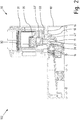
- FIG. 1 shows a section through the foot portion of a lift-slide door 101 with a floor sill 10 and a movably mounted thereon wing 30.
- the bottom sill 10 has in the right part, which faces a building inside, a top surface 16 which by a Laufschienenabilitynut 11th is interrupted, in which a rail profile 20 is inserted.
- the rail profile 20 has a track rail 21st
- the threshold 10 is formed in the illustrated embodiment of several individual aluminum profiles. There are three individual profiles provided, which are connected in pairs by two non-heat-conducting webs and are decoupled from each other via additional Isolierstoffein accounts.
- the wing 30 includes, among other things, a wing profile 31 formed of plastic.
- An inserted steel reinforcing profile 32 serves on the one hand the stiffening of the wing profile 31 and on the other hand has a fitting groove for receiving a roller carriage 35, on the rollers 33 of the wings 30 is mounted on the bottom threshold 10.
- the rollers 33 each have a concavely rounded, trough-shaped running surface into which the track rail 21 engages.
- an additional guide profile 40 is provided on the wing 30 according to the invention, which engages with a xiphon process 41 in a separate, narrow guide groove 18 which is formed in the ground sill.
- the guide profile 40 is connected directly over the entire length of the airfoil 31, and the guide groove 18 is part of the threshold profile.
- the Laufschieneningnut 11 and the guide groove 18 are separated by a profile web in the bottom threshold 10 from each other.
- FIG. 2 shows a second embodiment of a lift-slide door 102.
- the bottom threshold 10 is identical to that in FIG. 1 formed threshold formed.
- the wing 30 ' is identical in terms of the wing profile 31, the reinforcing profile 32 and the rollers 33 on the roller carriage 35 to the first described embodiment of the lift-slide door 101.
- Different is the formation of the guide profile 40' with the downwardly projecting sword 41th ', which engages in the guide groove 18 on the threshold 10.
- the guide profile 40 ' is in the in FIG. 2 illustrated embodiment of the lift-slide door 102 mounted directly on the roller carriage 35 and extends over the entire length of the roller carriage 35th
- FIG. 3 illustrated third embodiment of a lifting-sliding door 103 according to the invention
- the wing 30 opposite to in FIG. 2 shown lift-slide door 102 completely unchanged, ie the guide profile 40 'is connected to the roller carriage 35.
- the oracle extension 41 ' is also unchanged and engages in the same position as in the previously described embodiment in a guide groove 28' at a threshold 10 'a.
- the guide groove 28 ' is not formed directly in the profile of the bottom threshold 10', but part of a track profile 20 ', in its right area, side of a track rail 21', a U has-shaped profile region, in which the guide groove 28 'is formed. All profile regions of the rail profile 20 'on both sides of the rail web 21' go flush in the corresponding top surfaces 16 'on top of the thresholds 10' over.
- the floor sill profile 10 ' has, in addition to a track receiving groove 11', a further receiving area 12 ', which extends below the top surface 16'.
- FIG. 4 a lift-slide door 100 is shown, which does not correspond directly to the object of the invention, because the wing 30 no guide profile is provided.
- the threshold 10 ' is unchanged from the in FIG. 3 illustrated embodiment, however, differs in FIG. 5 Threshold shown 10 'in that there is a track profile 20 "is used, which has no guide, but with an angular profile web 22" is provided, which covers the reserved in the thresholds 10' for a guide groove receiving area 12 'in addition to the Schienenamnam 11' ,
- the threshold 10 'after FIG. 4 as well as the wing 30 can thus at any time to the embodiment according to the invention FIG. 3 be converted by the track profile 20 'with the guide groove 28' ( Fig. 3 ) is inserted into the threshold 10 'and at least one guide profile is attached to the wing 30.
- FIG. 5 Another embodiment of a lift-and-slide door 104 according to the invention shows FIG. 5 ,
- a threshold 10 is provided, which is widened somewhat towards the inside of the building.
- a guide groove 18 is formed in the region of the threshold profile directly adjoining the inside of the building.
- engages a xiphon process 41 "of a guide member 40” which is mounted on the inner visible surface of the sash 31. Subsequent assembly to existing wing system is thus possible.
Landscapes
- Engineering & Computer Science (AREA)
- Civil Engineering (AREA)
- Structural Engineering (AREA)
- Support Devices For Sliding Doors (AREA)
Abstract
Description
- Die Erfindung betrifft eine Hebe-Schiebe-Tür mit einer barrierefreien Bodenschwelle mit den Merkmalen des Oberbegriffs des Anspruchs 1.
- Herkömmliche Bodenschwellen für Hebe-Schiebetüren ragen über das Niveau des Fertigfußbodens hinaus und bilden damit eine Barriere, insbesondere für Gehbehinderte. Hiervon kann eine Stolpergefahr ausgehen oder sogar ein nicht zu überwindendes Hindernis für Personen gebildet werden, die auf eine rollbare Gehhilfe oder einen Rollstuhl angewiesen sind.
- Daher besteht heutzutage zunehmend die Forderung, Schwellen in Gebäuden zu vermeiden oder die notwendigen Schwellen barrierefrei auszubilden, wobei nach der geltenden Definition der DIN 18040-2 jegliche Aufkantung maximal 20 mm über Fertigfußbodenniveau betragen darf, um noch als barrierefrei zu gelten. Darüber hinaus werden bereits sogenannte "Nullbarrieren" gefordert, also Schwellen, die vollständig bündig auf das Fertigfußbodenniveau übergehen. Andererseits ist eine Aufkantung an der Bodenschwelle zumindest für einen Laufschienensteg zwingend erforderlich, welcher die Führungsschiene für den Laufrollenwagen der Hebe-Schiebe-Tür bildet. Der Laufrollenwagen besitzt Laufrollen mit einer außenumfänglichen, konkaven Vertiefung, die auf dem gerundeten Laufschienensteg läuft. Hierüber wird die Spurführung des schiebebeweglichen Flügels auf der Bodenschwelle erreicht.
- Wird die Höhe des Laufschienenstegs reduziert, um die Höhe der Aufkantung an der Oberseite der Bodenschwelle zu reduzieren und damit die Barriere zu mindern oder zu beseitigen, so wird zwangsläufig der formschlüssige Eingriff zwischen Laufrollen und dem Laufschienensteg reduziert. Der Formschluss reicht zwar für eine Verschiebung des Flügels im normalen Betrieb aus. Da der Flügel aber auch vertikal beweglich sein muss, um montiert werden zu können und eine leichtgängige Verschiebung zu ermöglichen, kann der Flügel bei einem Einbruch möglicherweise soweit angehoben werden, dass der formschlüssige Eingriff seiner Laufrollen mit dem Laufschienensteg aufgehoben wird, so dass auf diese Weise ein gewaltsamer Zugang ins Gebäude möglich ist.
- Die Aufgabe der vorliegenden Erfindung besteht somit darin, den verschiebbaren Flügel einer Hebeschiebetür gegen Ausheben zu sichern und dennoch die Höhe des Laufschienenstegs auf dem Laufschienenprofil reduzieren zu können, um eine weitest mögliche Barrierefreiheit an dieser Stelle zu erreichen.
- Diese Aufgabe wird durch eine Hebe-Schiebe-Tür mit den Merkmalen des Anspruchs 1 gelöst.
- Die grundsätzlich bekannte Lagerung des Schiebeflügels über Laufrollen, die eine rillenförmige Lauffläche aufweisen und damit auf einem Laufschienensteg abrollen, kann nach der Erfindung grundsätzlich beibehalten werden. Die Erfindung hat also den Vorteil, dass keine neuen Beschläge wie z. B. die Laufrollenwagen, benötigt werden. Um den Flügel zusätzlich gegen solche Kräfte zu sichern, die senkrecht zur Ebene des Flügels wirken, sieht die Erfindung wenigstens ein Eingriffselement vor, das mit dem Flügel fest verbunden ist und das eine rinnenförmige Vertiefung in der Bodenschwelle eingreift, die eine Führungsnut bildet. Die Führungsnut ist von etwaigen Vertiefungen seitlich des Laufschienenstegs getrennt. Ihre Querschnittsbreite entspricht der Querschnittsbreite des Eingriffselement mit nur geringen Zuschlägen für seitliches Spiel, so dass zwar eine ungehinderte Bewegung des Schiebeflügels möglich ist, aber eine seitliche Verschiebung des
- Der Eingriff besteht vorzugsweise dauerhaft, also sowohl in der gegenüber der Bodenschwelle abgesenkten wie der angehobenen Stellung des Flügels.
- Die Eingriffstiefe des Eingriffselements ist dabei vorzugsweise so gewählt, dass dieser bei maximal im Rahmen angehobenem Schiebeflügel immer noch mindestens 5 mm tief in die Führungsnut hineinragt, möglichst sogar noch tiefer. Die Führungsnut muss entsprechend tief ausgebildet sein, damit das entsprechend lang ausgebildete Eingriffselement auch bei abgesenktem Flügel nicht auf den Grund der Führungsnut stößt.
- Ein Eingriffselement kann grundsätzlich nur an einigen Punkten vorhanden sein. Gemäß allen bevorzugten Ausführungsformen der Erfindungen ist jedoch vorgesehen, ein längliches Führungsprofil direkt am Flügel zu befestigen, das einen nach unten ragenden Schwertfortsatz besitzt, welcher das Eingriffselement bildet und in die Führungsnut eingreift.
- Die Führungsnut in der Bodenschwelle kann entweder im Bodenschwellenprofil selbst ausgebildet sein oder Teil des Laufschienenprofils sein. Die Integration in die Laufschiene hat den Vorteil, dass dabei durch die Verwendung verschiedener Laufschienenprofile mit demselben Bodenschwellenprofil sowohl eine herkömmliche Ausbildung der Bodenschwelle ohne zusätzliche Sicherungsführung möglich ist, wie auch eine nach der Erfindung verbesserte lineare Führung und Sicherung des Schiebeflügels gegen in Durchgangsrichtung wirkende Kräfte.
- Hinsichtlich der Positionierung des Eingriffselements, insbesondere des Führungsprofils, sind verschiedene Varianten denkbar. Dieses kann innen mit dem Flügelprofil verbunden sein oder auch auf eine Sichtfläche aufgesetzt sein. Außerdem kann es direkt mit dem Laufrollenwagen verbunden sein. Entsprechend kann die zugehörige Nut mehr in einem zentralen Bereich der oberen Deckfläche an der Bodenschwelle angeordnet sein, oder auch maximal zum Rand an der Gebäudeinnenseite hin versetzt sein. Bevorzugt erfolgt die Positionierung an der zur Gebäudeinnenseite weisenden Seite der Laufrollen, sodass ein Zugriff auf das dahinterliegende Führungsprofil deutlich erschwert ist.
- Es ist nicht notwendig ist, dass sich das Führungsprofil über die gesamte Länge der Bodenschwelle erstreckt, sondern die erfindungsgemäße Wirkung wird auch durch einzelne Abschnitte eines Führungsprofils erreicht, die beispielsweise nur an den einzelnen Laufrollenwagen befestigt sind. Wichtiger als die Länge des Führungsprofils ist die ausreichend Eingriffstiefe des Schwertfortsatzes in der Führungsnut.
- Die Breite des Schwertfortsatzes und der Führungsnut sollten möglichst gering sein, damit die nach oben offene Führungsnut bei geöffneter Tür optisch wenig störend wirkt und damit keine größeren Schmutzansammlungen in der Führungsnut entstehen können.
- Weitere vorteilhafte Ausführungen der vorliegenden Erfindung werden unter Bezug auf die in den Zeichnungen dargestellten Ausführungsbeispiele erläutert. Die Figuren zeigen im jeweils in einer Schnittansicht:
- Figur 1
- eine erste Ausführungsform einer erfindungsgemäßen Hebe-Schiebetür;
- Figur 2
- eine zweite Ausführungsform einer erfindungsgemäßen Hebe-Schiebetür;
- Figur 3
- eine dritte Ausführungsform einer erfindungsgemäßen Hebe-Schiebetür;
- Figur 4
- eine herkömmliche Hebe-Schiebe-Tür ohne Führungsprofil als Abwandlung der erfindungsgemäßen Hebe-Schiebe-Tür nach Figur 3 und
- Figur 5
- eine vierte Ausführungsform einer erfindungsgemäßen Hebe-Schiebe-Tür.
-
Figur 1 zeigt einen Schnitt durch den Fußbereich einer Hebe-Schiebe-Tür 101 mit einer Bodenschwelle 10 und einem beweglich darauf gelagerten Flügel 30. Die Bodenschwelle 10 weist in dem rechten Teil, der einer Gebäudeinnenseite zugewandt ist, eine Deckfläche 16 auf, die durch eine Laufschienenaufnahmenut 11 unterbrochen ist, in welche ein Laufschienenprofil 20 eingesetzt ist. Das Laufschienenprofil 20 besitzt einen Laufschienensteg 21. - In Verlängerung der Deckfläche 16 erstreckt sich ein horizontaler Abschnitt eines Zusatzprofils 19, das mit Ausnehmungen versehen ist, sodass dort anfallendes Wasser nach unten abtropft und auf einem Wetterschenkel 17 nach außen abgeleitet wird. Die Bodenschwelle 10 ist im dargestellten Ausführungsbeispiel aus mehreren einzelnen Aluminiumprofilen gebildet. Es sind drei Einzelprofile vorgesehen, die durch zwei nicht-wärmeleitende Stege paarweise miteinander verbunden sind und über zusätzliche Isolierstoffeinsätze voneinander entkoppelt sind.
- Der Flügel 30 umfasst unter anderem ein Flügelprofil 31, das aus Kunststoff gebildet ist. Ein eingesetztes Stahl-Verstärkungsprofil 32 dient zum einen der Aussteifung des Flügelprofils 31 und besitzt zum anderen eine Beschlagnut zur Aufnahme eines Laufrollenwagens 35, über dessen Laufrollen 33 der Flügel 30 auf der Bodenschwelle 10 gelagert ist. Die Laufrollen 33 besitzen jeweils eine konkav gerundete, rinnenförmige Lauffläche, in welche der Laufschienensteg 21 eingreift.
- Neben der soweit an sich bekannten Ausbildung einer Hebe-Schiebe-Tür 101 ist erfindungsgemäß ein zusätzliches Führungsprofil 40 am Flügel 30 vorgesehen, das mit einem Schwertfortsatz 41 in eine separate, schmale Führungsnut 18 eingreift, welche in der Bodenschwelle ausgebildet ist. In dem in
Figur 1 dargestellten Ausführungsbeispiel ist das Führungsprofil 40 direkt über die gesamte Länge mit dem Flügelprofil 31 verbunden, und die Führungsnut 18 ist Teil des Bodenschwellenprofils. Die Laufschienenaufnahmenut 11 und die Führungsnut 18 sind durch einen Profilsteg in der Bodenschwelle 10 voneinander getrennt. -
Figur 2 zeigt eine zweite Ausführungsform einer Hebe-Schiebe-Tür 102. Die Bodenschwelle 10 ist identisch zu der inFigur 1 abgebildeten Bodenschwelle ausgebildet. Auch der Flügel 30' ist hinsichtlich des Flügelprofils 31, des Verstärkungsprofils 32 und der Laufrollen 33 am Laufrollenwagen 35 identisch zu der ersten beschriebenen Ausführungsform der Hebe-Schiebe-Tür 101. Unterschiedlich ist die Ausbildung des Führungsprofils 40' mit dem nach unten ragenden Schwertfortsatz 41', der in die Führungsnut 18 an der Bodenschwelle 10 eingreift. Das Führungsprofil 40' ist bei der inFigur 2 dargestellten Ausführungsform der Hebe-Schiebe-Tür 102 direkt am Laufrollenwagen 35 angebracht und erstreckt sich jeweils über die gesamte Länge des Laufrollenwagens 35. - Bei einer in
Figur 3 dargestellten dritten Ausführungsform einer erfindungsgemäßen Hebe-Schiebe-Tür 103 ist der Flügel 30 gegenüber der inFigur 2 dargestellten Hebe-Schiebe-Tür 102 vollständig unverändert, d. h. das Führungsprofil 40' ist mit dem Laufrollenwagen 35 verbunden. Der Schwertfortsatz 41' ist ebenso unverändert und greift an der gleichen Position wie bei der zuvor beschriebenen Ausführungsform in eine Führungsnut 28' an einer Bodenschwelle 10' ein. - Unterschiedlich bei der Hebe-Schiebe-Tür 103 ist, dass die Führungsnut 28' nicht direkt in das Profil der Bodenschwelle 10' eingeformt ist, sondern Teil eines Laufschienenprofils 20' ist, das in seinem rechten Bereich, seitlich eines Laufschienenstegs 21', einen U-förmigen Profilbereich besitzt, in dem die Führungsnut 28' ausgebildet ist. Alle Profilbereiche des Laufschienenprofils 20' beidseits des Laufschienenstegs 21' gehen bündig in die entsprechenden Deckflächen 16' auf der Oberseite der Bodenschwellen 10' über. Um das Laufschienenprofil aufzunehmen, besitzt das Bodenschwellenprofil 10' neben einer Laufschienenaufnahmenut 11' einen weiteren Aufnahmebereich 12', der sich bis unterhalb der Deckfläche 16' erstreckt.
- In
Figur 4 ist eine Hebe-Schiebe-Tür 100 dargestellt, die nicht unmittelbar dem Gegenstand der Erfindung entspricht, weil am Flügel 30 kein Führungsprofil vorgesehen ist. Die Bodenschwelle 10' ist unverändert gegenüber der inFigur 3 dargestellten Ausführungsform, jedoch unterscheidet sich die inFigur 5 gezeigte Bodenschwelle 10' dadurch, dass dort ein Laufschienenprofil 20" eingesetzt ist, das keine Führungsnut aufweist, aber mit einem winkelförmigen Profilsteg 22" versehen ist, der den in der Bodenschwellen 10' für eine Führungsnut reservierten Aufnahmebereich 12' neben der Laufschienenaufnahmenut 11' überdeckt. Die Bodenschwelle 10' nachFigur 4 wie auch der Flügel 30 können somit jederzeit auf die erfindungsgemäße Ausführungsform nachFigur 3 umgerüstet werden, indem das Laufschienenprofil 20' mit der Führungsnut 28' (Fig. 3 ) in die Bodenschwelle 10' eingesetzt wird und wenigstens ein Führungsprofil am Flügel 30 angebracht wird. - Eine weitere Ausführungsform einer Hebe-Schiebe-Tür 104 nach der Erfindung zeigt
Figur 5 . Hierbei ist eine Bodenschwelle 10" vorgesehen, die zur Gebäudeinnenseite hin etwas verbreitert ist. In dem sich unmittelbar an die Gebäudeinnenseite anschließenden Bereich des Bodenschwellenprofils ist eine Führungsnut 18"ausgebildet. Hierin greift ein Schwertfortsatz 41" eines Führungselements 40" ein, welches auf der inneren Sichtfläche des Flügelprofils 31 angebracht ist. Eine nachträgliche Montage an vorhandenen Flügelsystem ist somit möglich. Bei dieser Ausführungsform ist es aus optischen Gründen vorteilhaft, wenn sich das Führungsprofil 40" über die gesamte Breite des Flügels 30 erstreckt.
Claims (8)
- Hebe-Schiebe-Tür (101, 102, 103, 104) mit einer barrierefreien Bodenschwelle (10; 10'; 10") mit wenigstens einer Laufschienenaufnahmenut (11, 11', 11"), in die ein Laufschienenprofil (20; 20'; 20") mit einem Laufschienensteg (21; 21'; 21") einsetzbar ist,
und mit einem über Laufrollen (33) auf dem Laufschienenprofil (20; 20'; 20") verschiebbaren Flügel (30);
dadurch gekennzeichnet, dass am Flügel (30) wenigstens ein Eingriffselement (41; 41'; 41") angeordnet ist, das zumindest in der gegenüber der Bodenschwelle (10; 10'; 10") abgesenkten Stellung des Flügels (30) in wenigstens eine, sich parallel zum Laufschienensteg (21; 21'; 21") erstreckende Führungsnut (18; 18"; 28") an der Bodenschwelle (10; 10'; 10") eingreift, wobei die Laufschienenaufnahmenut (11) und die Führungsnut (18) voneinander getrennt sind. - Hebe-Schiebe-Tür (101, 102, 103, 104) nach Anspruch 1, dadurch gekennzeichnet, dass das Eingriffselement (41; 41'; 41") in der gegenüber der Bodenschwelle (10; 10'; 10") angehobenen wie in der abgesenkten Stellung des Flügels (30) in die Führungsnut (18; 18"; 28') eingreift.
- Hebe-Schiebe-Tür (101, 102, 103, 104) nach Anspruch 1 oder 2, dadurch gekennzeichnet, dass das Eingriffselement durch einen Schwertfortsatz (41; 41'; 41") gebildet ist, der sich von der Unterseite eines mit dem Flügel (30) verbundenen Führungsprofils (40; 40'; 40") aus in die Führungsnut (18; 18"; 28') erstreckt.
- Hebe-Schiebe-Tür (102, 103) nach einem der Ansprüche 1 bis 3, dadurch gekennzeichnet, dass das Führungsprofil (40') an einem Laufrollenwagen (35) angebracht ist.
- Hebe-Schiebe-Tür (101) nach einem der Ansprüche 1 bis 3, dadurch gekennzeichnet, dass das Führungsprofil (40') im Inneren des Profilquerschnitts an dem Flügel (30) angebracht ist.
- Hebe-Schiebe-Tür (104) nach einem der Ansprüche 1 bis 3, dadurch gekennzeichnet, dass das Führungsprofil (40') an einer gebäudeinnenseitigen Sichtfläche des Flügels (30) angebracht ist.
- Hebe-Schiebe-Tür (101, 102, 104) nach einem der Ansprüche 1 bis 6, dadurch gekennzeichnet, dass die Führungsnut (18; 18") in der Bodenschwelle (10; 10") ausgebildet ist.
- Hebe-Schiebe-Tür (103) nach einem der Ansprüche 1 bis 6, dadurch gekennzeichnet, dass die Führungsnut (28') im Laufschienenprofil (20') ausgebildet ist.
Priority Applications (1)
| Application Number | Priority Date | Filing Date | Title |
|---|---|---|---|
| PL18215321T PL3502399T3 (pl) | 2017-12-21 | 2018-12-21 | Drzwi podnoszono-przesuwne z progiem bezbarierowym |
Applications Claiming Priority (1)
| Application Number | Priority Date | Filing Date | Title |
|---|---|---|---|
| DE102017130912.8A DE102017130912A1 (de) | 2017-12-21 | 2017-12-21 | Hebe-Schiebe-Tür mit einer barrierefreien Bodenschwelle |
Publications (2)
| Publication Number | Publication Date |
|---|---|
| EP3502399A1 true EP3502399A1 (de) | 2019-06-26 |
| EP3502399B1 EP3502399B1 (de) | 2020-09-23 |
Family
ID=64900776
Family Applications (1)
| Application Number | Title | Priority Date | Filing Date |
|---|---|---|---|
| EP18215321.3A Active EP3502399B1 (de) | 2017-12-21 | 2018-12-21 | Hebe-schiebe-tür mit einer barrierefreien bodenschwelle |
Country Status (3)
| Country | Link |
|---|---|
| EP (1) | EP3502399B1 (de) |
| DE (1) | DE102017130912A1 (de) |
| PL (1) | PL3502399T3 (de) |
Cited By (1)
| Publication number | Priority date | Publication date | Assignee | Title |
|---|---|---|---|---|
| NL2037785B1 (en) * | 2024-05-27 | 2025-12-09 | Giemeta Luvema Bv | Threshold element for a sliding door arrangement |
Families Citing this family (7)
| Publication number | Priority date | Publication date | Assignee | Title |
|---|---|---|---|---|
| DE202020107352U1 (de) | 2020-12-17 | 2022-03-21 | REHAU Industries SE & Co. KG | Flügel für ein Fenster oder eine Tür sowie Verstärkungselement für einen derartigen Flügel |
| DE102022204891A1 (de) | 2022-05-17 | 2023-11-23 | Roto Frank Fenster- und Türtechnologie GmbH | Barrierefreie Schiebetür mit einem Laufwagen für einen querabstellbaren Flügel |
| DE102022204890A1 (de) | 2022-05-17 | 2023-11-23 | Roto Frank Fenster- und Türtechnologie GmbH | Barrierefreie Schiebetür mit einem querabstellbaren Flügel |
| DE102023204117A1 (de) | 2023-05-04 | 2024-11-07 | Roto Frank Fenster- und Türtechnologie GmbH | Fenster oder Tür mit einem modularen Schwellensystem |
| DE102023124723A1 (de) * | 2023-09-13 | 2025-03-13 | UNILUX GmbH | Nullschwelle für eine Tür |
| DE102023133792A1 (de) * | 2023-12-04 | 2025-06-05 | Salamander Industrie-Produkte Gmbh | Bodenbrücke, Schwelle, Schiebetür- und/oder Schiebefenstersystem |
| DE102024204349A1 (de) * | 2024-05-08 | 2025-11-13 | Roto Frank Fenster- und Türtechnologie GmbH | Rollwagen, Rollwagenanordnung und Fenster oder Tür, mit Haltesicherung |
Citations (2)
| Publication number | Priority date | Publication date | Assignee | Title |
|---|---|---|---|---|
| NL2004524C2 (nl) * | 2010-04-08 | 2011-10-11 | Smits Gemert B V | Schuifdeurinrichting. |
| PL66739Y1 (pl) * | 2011-08-05 | 2013-09-30 | Aluprof Spolka Akcyjna | Drzwi podnoszono-przesuwne |
Family Cites Families (2)
| Publication number | Priority date | Publication date | Assignee | Title |
|---|---|---|---|---|
| US4633615A (en) * | 1985-07-08 | 1987-01-06 | Watsco Inc. | Track-inter-locking roller wheel assembly for sliding patio doors |
| AT511798B1 (de) * | 2011-12-29 | 2013-03-15 | Ifn Holding Ag | Bodenschwelle für eine hebe/schiebetür |
-
2017
- 2017-12-21 DE DE102017130912.8A patent/DE102017130912A1/de active Pending
-
2018
- 2018-12-21 EP EP18215321.3A patent/EP3502399B1/de active Active
- 2018-12-21 PL PL18215321T patent/PL3502399T3/pl unknown
Patent Citations (2)
| Publication number | Priority date | Publication date | Assignee | Title |
|---|---|---|---|---|
| NL2004524C2 (nl) * | 2010-04-08 | 2011-10-11 | Smits Gemert B V | Schuifdeurinrichting. |
| PL66739Y1 (pl) * | 2011-08-05 | 2013-09-30 | Aluprof Spolka Akcyjna | Drzwi podnoszono-przesuwne |
Cited By (1)
| Publication number | Priority date | Publication date | Assignee | Title |
|---|---|---|---|---|
| NL2037785B1 (en) * | 2024-05-27 | 2025-12-09 | Giemeta Luvema Bv | Threshold element for a sliding door arrangement |
Also Published As
| Publication number | Publication date |
|---|---|
| PL3502399T3 (pl) | 2021-03-08 |
| EP3502399B1 (de) | 2020-09-23 |
| DE102017130912A1 (de) | 2019-06-27 |
Similar Documents
| Publication | Publication Date | Title |
|---|---|---|
| EP3502399B1 (de) | Hebe-schiebe-tür mit einer barrierefreien bodenschwelle | |
| EP3502401B1 (de) | Barrierefreie bodenschwelle für eine hebe-schiebe-tür | |
| EP3488065B1 (de) | Bodenschwellensystem für einen verschiebbaren flügel als schiebeflügel odr verschiebbaren hebe-schiebeflügel eines fensters oder einer tür | |
| DE202008013043U1 (de) | Hebe-Schiebe-Fenster oder -Tür sowie Abdichtelement | |
| EP3527763B1 (de) | Schiebewandanordnung mit abdeckelement | |
| EP3225771B1 (de) | Bodenschwelle für eine schiebetür und schiebetür | |
| WO1995020712A1 (de) | Horizontalschiebefenster mit mindestens einem quer zur rahmenebene bewegbaren schiebeflügel | |
| WO2018166811A1 (de) | Bodenschwellensystem für einen verschiebbaren flügel als schiebeflügel oder verschiebbaren hebe-schiebeflügel eines fensters oder einer tür | |
| EP1312743B1 (de) | Sperr- und Sicherungsvorrichtung für einen Hebe- und Schiebeflügel; Treibstangenbeschlag mit einer solchen Vorrichtung; Hebe- und Schiebetür bzw. -fenster mit einer solchen Vorrichtung | |
| EP3219893A1 (de) | Mitteldichtungsblock für eine hebeschiebtür | |
| DE102022204891A1 (de) | Barrierefreie Schiebetür mit einem Laufwagen für einen querabstellbaren Flügel | |
| EP3527767B1 (de) | Hebeschiebe-element | |
| WO2011067210A2 (de) | Schiebewand mit wenigstens zwei flügeln | |
| EP0978622B1 (de) | Verfahrbare Türflügelanordnung | |
| DE102023117279A1 (de) | Schiebetüranordnung | |
| EP3879059B1 (de) | Bodenschwelle | |
| DE202007019187U1 (de) | Sektionaltor | |
| DE102022204890A1 (de) | Barrierefreie Schiebetür mit einem querabstellbaren Flügel | |
| EP2072744B1 (de) | Zargenprofil für eine Hebe-Schiebetür | |
| DE202007002319U1 (de) | Schließteil | |
| EP3527768A1 (de) | Anordnung für ein hebeschiebe-element | |
| DE19850276B4 (de) | Laufschiene für eine Insektenschutztür | |
| EP2362047B1 (de) | Hebe-Schiebe-Tür oder Hebe-Schiebe-Fenster | |
| EP1020600A2 (de) | Türblattführung sowie zugehörige Türflügelanordnung, insbesondere für automatische Schiebetüren | |
| DE60000324T2 (de) | Beschlagelement bzw. Schliessblech oder anderes in einer einklemmenden "u" oder "t" formigen Nut zu befestigen |
Legal Events
| Date | Code | Title | Description |
|---|---|---|---|
| PUAI | Public reference made under article 153(3) epc to a published international application that has entered the european phase |
Free format text: ORIGINAL CODE: 0009012 |
|
| STAA | Information on the status of an ep patent application or granted ep patent |
Free format text: STATUS: THE APPLICATION HAS BEEN PUBLISHED |
|
| AK | Designated contracting states |
Kind code of ref document: A1 Designated state(s): AL AT BE BG CH CY CZ DE DK EE ES FI FR GB GR HR HU IE IS IT LI LT LU LV MC MK MT NL NO PL PT RO RS SE SI SK SM TR |
|
| AX | Request for extension of the european patent |
Extension state: BA ME |
|
| STAA | Information on the status of an ep patent application or granted ep patent |
Free format text: STATUS: REQUEST FOR EXAMINATION WAS MADE |
|
| 17P | Request for examination filed |
Effective date: 20191220 |
|
| RBV | Designated contracting states (corrected) |
Designated state(s): AL AT BE BG CH CY CZ DE DK EE ES FI FR GB GR HR HU IE IS IT LI LT LU LV MC MK MT NL NO PL PT RO RS SE SI SK SM TR |
|
| GRAP | Despatch of communication of intention to grant a patent |
Free format text: ORIGINAL CODE: EPIDOSNIGR1 |
|
| STAA | Information on the status of an ep patent application or granted ep patent |
Free format text: STATUS: GRANT OF PATENT IS INTENDED |
|
| INTG | Intention to grant announced |
Effective date: 20200518 |
|
| GRAS | Grant fee paid |
Free format text: ORIGINAL CODE: EPIDOSNIGR3 |
|
| GRAA | (expected) grant |
Free format text: ORIGINAL CODE: 0009210 |
|
| STAA | Information on the status of an ep patent application or granted ep patent |
Free format text: STATUS: THE PATENT HAS BEEN GRANTED |
|
| AK | Designated contracting states |
Kind code of ref document: B1 Designated state(s): AL AT BE BG CH CY CZ DE DK EE ES FI FR GB GR HR HU IE IS IT LI LT LU LV MC MK MT NL NO PL PT RO RS SE SI SK SM TR |
|
| REG | Reference to a national code |
Ref country code: GB Ref legal event code: FG4D Free format text: NOT ENGLISH |
|
| REG | Reference to a national code |
Ref country code: CH Ref legal event code: EP |
|
| REG | Reference to a national code |
Ref country code: DE Ref legal event code: R096 Ref document number: 502018002540 Country of ref document: DE |
|
| REG | Reference to a national code |
Ref country code: IE Ref legal event code: FG4D Free format text: LANGUAGE OF EP DOCUMENT: GERMAN |
|
| REG | Reference to a national code |
Ref country code: AT Ref legal event code: REF Ref document number: 1316537 Country of ref document: AT Kind code of ref document: T Effective date: 20201015 |
|
| REG | Reference to a national code |
Ref country code: NL Ref legal event code: FP |
|
| REG | Reference to a national code |
Ref country code: CH Ref legal event code: NV Representative=s name: SCHMAUDER AND PARTNER AG PATENT- UND MARKENANW, CH |
|
| PG25 | Lapsed in a contracting state [announced via postgrant information from national office to epo] |
Ref country code: FI Free format text: LAPSE BECAUSE OF FAILURE TO SUBMIT A TRANSLATION OF THE DESCRIPTION OR TO PAY THE FEE WITHIN THE PRESCRIBED TIME-LIMIT Effective date: 20200923 Ref country code: GR Free format text: LAPSE BECAUSE OF FAILURE TO SUBMIT A TRANSLATION OF THE DESCRIPTION OR TO PAY THE FEE WITHIN THE PRESCRIBED TIME-LIMIT Effective date: 20201224 Ref country code: SE Free format text: LAPSE BECAUSE OF FAILURE TO SUBMIT A TRANSLATION OF THE DESCRIPTION OR TO PAY THE FEE WITHIN THE PRESCRIBED TIME-LIMIT Effective date: 20200923 Ref country code: HR Free format text: LAPSE BECAUSE OF FAILURE TO SUBMIT A TRANSLATION OF THE DESCRIPTION OR TO PAY THE FEE WITHIN THE PRESCRIBED TIME-LIMIT Effective date: 20200923 Ref country code: NO Free format text: LAPSE BECAUSE OF FAILURE TO SUBMIT A TRANSLATION OF THE DESCRIPTION OR TO PAY THE FEE WITHIN THE PRESCRIBED TIME-LIMIT Effective date: 20201223 Ref country code: BG Free format text: LAPSE BECAUSE OF FAILURE TO SUBMIT A TRANSLATION OF THE DESCRIPTION OR TO PAY THE FEE WITHIN THE PRESCRIBED TIME-LIMIT Effective date: 20201223 |
|
| PG25 | Lapsed in a contracting state [announced via postgrant information from national office to epo] |
Ref country code: LV Free format text: LAPSE BECAUSE OF FAILURE TO SUBMIT A TRANSLATION OF THE DESCRIPTION OR TO PAY THE FEE WITHIN THE PRESCRIBED TIME-LIMIT Effective date: 20200923 Ref country code: RS Free format text: LAPSE BECAUSE OF FAILURE TO SUBMIT A TRANSLATION OF THE DESCRIPTION OR TO PAY THE FEE WITHIN THE PRESCRIBED TIME-LIMIT Effective date: 20200923 |
|
| REG | Reference to a national code |
Ref country code: LT Ref legal event code: MG4D |
|
| PG25 | Lapsed in a contracting state [announced via postgrant information from national office to epo] |
Ref country code: CZ Free format text: LAPSE BECAUSE OF FAILURE TO SUBMIT A TRANSLATION OF THE DESCRIPTION OR TO PAY THE FEE WITHIN THE PRESCRIBED TIME-LIMIT Effective date: 20200923 Ref country code: PT Free format text: LAPSE BECAUSE OF FAILURE TO SUBMIT A TRANSLATION OF THE DESCRIPTION OR TO PAY THE FEE WITHIN THE PRESCRIBED TIME-LIMIT Effective date: 20210125 Ref country code: RO Free format text: LAPSE BECAUSE OF FAILURE TO SUBMIT A TRANSLATION OF THE DESCRIPTION OR TO PAY THE FEE WITHIN THE PRESCRIBED TIME-LIMIT Effective date: 20200923 Ref country code: EE Free format text: LAPSE BECAUSE OF FAILURE TO SUBMIT A TRANSLATION OF THE DESCRIPTION OR TO PAY THE FEE WITHIN THE PRESCRIBED TIME-LIMIT Effective date: 20200923 Ref country code: SM Free format text: LAPSE BECAUSE OF FAILURE TO SUBMIT A TRANSLATION OF THE DESCRIPTION OR TO PAY THE FEE WITHIN THE PRESCRIBED TIME-LIMIT Effective date: 20200923 Ref country code: LT Free format text: LAPSE BECAUSE OF FAILURE TO SUBMIT A TRANSLATION OF THE DESCRIPTION OR TO PAY THE FEE WITHIN THE PRESCRIBED TIME-LIMIT Effective date: 20200923 |
|
| PG25 | Lapsed in a contracting state [announced via postgrant information from national office to epo] |
Ref country code: IS Free format text: LAPSE BECAUSE OF FAILURE TO SUBMIT A TRANSLATION OF THE DESCRIPTION OR TO PAY THE FEE WITHIN THE PRESCRIBED TIME-LIMIT Effective date: 20210123 Ref country code: AL Free format text: LAPSE BECAUSE OF FAILURE TO SUBMIT A TRANSLATION OF THE DESCRIPTION OR TO PAY THE FEE WITHIN THE PRESCRIBED TIME-LIMIT Effective date: 20200923 Ref country code: ES Free format text: LAPSE BECAUSE OF FAILURE TO SUBMIT A TRANSLATION OF THE DESCRIPTION OR TO PAY THE FEE WITHIN THE PRESCRIBED TIME-LIMIT Effective date: 20200923 |
|
| REG | Reference to a national code |
Ref country code: DE Ref legal event code: R097 Ref document number: 502018002540 Country of ref document: DE |
|
| PG25 | Lapsed in a contracting state [announced via postgrant information from national office to epo] |
Ref country code: SK Free format text: LAPSE BECAUSE OF FAILURE TO SUBMIT A TRANSLATION OF THE DESCRIPTION OR TO PAY THE FEE WITHIN THE PRESCRIBED TIME-LIMIT Effective date: 20200923 |
|
| PLBE | No opposition filed within time limit |
Free format text: ORIGINAL CODE: 0009261 |
|
| STAA | Information on the status of an ep patent application or granted ep patent |
Free format text: STATUS: NO OPPOSITION FILED WITHIN TIME LIMIT |
|
| PG25 | Lapsed in a contracting state [announced via postgrant information from national office to epo] |
Ref country code: DK Free format text: LAPSE BECAUSE OF FAILURE TO SUBMIT A TRANSLATION OF THE DESCRIPTION OR TO PAY THE FEE WITHIN THE PRESCRIBED TIME-LIMIT Effective date: 20200923 Ref country code: SI Free format text: LAPSE BECAUSE OF FAILURE TO SUBMIT A TRANSLATION OF THE DESCRIPTION OR TO PAY THE FEE WITHIN THE PRESCRIBED TIME-LIMIT Effective date: 20200923 Ref country code: MC Free format text: LAPSE BECAUSE OF FAILURE TO SUBMIT A TRANSLATION OF THE DESCRIPTION OR TO PAY THE FEE WITHIN THE PRESCRIBED TIME-LIMIT Effective date: 20200923 |
|
| 26N | No opposition filed |
Effective date: 20210624 |
|
| PG25 | Lapsed in a contracting state [announced via postgrant information from national office to epo] |
Ref country code: LU Free format text: LAPSE BECAUSE OF NON-PAYMENT OF DUE FEES Effective date: 20201221 Ref country code: IE Free format text: LAPSE BECAUSE OF NON-PAYMENT OF DUE FEES Effective date: 20201221 |
|
| PG25 | Lapsed in a contracting state [announced via postgrant information from national office to epo] |
Ref country code: TR Free format text: LAPSE BECAUSE OF FAILURE TO SUBMIT A TRANSLATION OF THE DESCRIPTION OR TO PAY THE FEE WITHIN THE PRESCRIBED TIME-LIMIT Effective date: 20200923 Ref country code: MT Free format text: LAPSE BECAUSE OF FAILURE TO SUBMIT A TRANSLATION OF THE DESCRIPTION OR TO PAY THE FEE WITHIN THE PRESCRIBED TIME-LIMIT Effective date: 20200923 Ref country code: CY Free format text: LAPSE BECAUSE OF FAILURE TO SUBMIT A TRANSLATION OF THE DESCRIPTION OR TO PAY THE FEE WITHIN THE PRESCRIBED TIME-LIMIT Effective date: 20200923 |
|
| PG25 | Lapsed in a contracting state [announced via postgrant information from national office to epo] |
Ref country code: MK Free format text: LAPSE BECAUSE OF FAILURE TO SUBMIT A TRANSLATION OF THE DESCRIPTION OR TO PAY THE FEE WITHIN THE PRESCRIBED TIME-LIMIT Effective date: 20200923 |
|
| P01 | Opt-out of the competence of the unified patent court (upc) registered |
Effective date: 20230528 |
|
| GBPC | Gb: european patent ceased through non-payment of renewal fee |
Effective date: 20221221 |
|
| PG25 | Lapsed in a contracting state [announced via postgrant information from national office to epo] |
Ref country code: GB Free format text: LAPSE BECAUSE OF NON-PAYMENT OF DUE FEES Effective date: 20221221 |
|
| REG | Reference to a national code |
Ref country code: AT Ref legal event code: MM01 Ref document number: 1316537 Country of ref document: AT Kind code of ref document: T Effective date: 20231221 |
|
| PG25 | Lapsed in a contracting state [announced via postgrant information from national office to epo] |
Ref country code: AT Free format text: LAPSE BECAUSE OF NON-PAYMENT OF DUE FEES Effective date: 20231221 |
|
| PGFP | Annual fee paid to national office [announced via postgrant information from national office to epo] |
Ref country code: CH Payment date: 20250101 Year of fee payment: 7 |
|
| REG | Reference to a national code |
Ref country code: CH Ref legal event code: U11 Free format text: ST27 STATUS EVENT CODE: U-0-0-U10-U11 (AS PROVIDED BY THE NATIONAL OFFICE) Effective date: 20260101 |
|
| PGFP | Annual fee paid to national office [announced via postgrant information from national office to epo] |
Ref country code: FR Payment date: 20251217 Year of fee payment: 8 Ref country code: NL Payment date: 20251217 Year of fee payment: 8 |
|
| PGFP | Annual fee paid to national office [announced via postgrant information from national office to epo] |
Ref country code: BE Payment date: 20251223 Year of fee payment: 8 |
|
| PGFP | Annual fee paid to national office [announced via postgrant information from national office to epo] |
Ref country code: PL Payment date: 20251205 Year of fee payment: 8 |
|
| PGFP | Annual fee paid to national office [announced via postgrant information from national office to epo] |
Ref country code: DE Payment date: 20251222 Year of fee payment: 8 |
|
| PGFP | Annual fee paid to national office [announced via postgrant information from national office to epo] |
Ref country code: AT Payment date: 20260410 Year of fee payment: 5 |
|
| PGFP | Annual fee paid to national office [announced via postgrant information from national office to epo] |
Ref country code: IT Payment date: 20251231 Year of fee payment: 8 |