EP3502425A1 - Indicateur d'usure à base de capacité et procédé de mesure d'éloignement - Google Patents
Indicateur d'usure à base de capacité et procédé de mesure d'éloignement Download PDFInfo
- Publication number
- EP3502425A1 EP3502425A1 EP18214224.0A EP18214224A EP3502425A1 EP 3502425 A1 EP3502425 A1 EP 3502425A1 EP 18214224 A EP18214224 A EP 18214224A EP 3502425 A1 EP3502425 A1 EP 3502425A1
- Authority
- EP
- European Patent Office
- Prior art keywords
- wear indicator
- blade
- capacitance
- recited
- engine
- Prior art date
- Legal status (The legal status is an assumption and is not a legal conclusion. Google has not performed a legal analysis and makes no representation as to the accuracy of the status listed.)
- Granted
Links
Images



Classifications
-
- F—MECHANICAL ENGINEERING; LIGHTING; HEATING; WEAPONS; BLASTING
- F01—MACHINES OR ENGINES IN GENERAL; ENGINE PLANTS IN GENERAL; STEAM ENGINES
- F01D—NON-POSITIVE DISPLACEMENT MACHINES OR ENGINES, e.g. STEAM TURBINES
- F01D21/00—Shutting-down of machines or engines, e.g. in emergency; Regulating, controlling, or safety means not otherwise provided for
- F01D21/003—Arrangements for testing or measuring
-
- F—MECHANICAL ENGINEERING; LIGHTING; HEATING; WEAPONS; BLASTING
- F01—MACHINES OR ENGINES IN GENERAL; ENGINE PLANTS IN GENERAL; STEAM ENGINES
- F01D—NON-POSITIVE DISPLACEMENT MACHINES OR ENGINES, e.g. STEAM TURBINES
- F01D11/00—Preventing or minimising internal leakage of working-fluid, e.g. between stages
- F01D11/08—Preventing or minimising internal leakage of working-fluid, e.g. between stages for sealing space between rotor blade tips and stator
- F01D11/12—Preventing or minimising internal leakage of working-fluid, e.g. between stages for sealing space between rotor blade tips and stator using a rubstrip, e.g. erodible. deformable or resiliently-biased part
- F01D11/122—Preventing or minimising internal leakage of working-fluid, e.g. between stages for sealing space between rotor blade tips and stator using a rubstrip, e.g. erodible. deformable or resiliently-biased part with erodable or abradable material
-
- G—PHYSICS
- G01—MEASURING; TESTING
- G01B—MEASURING LENGTH, THICKNESS OR SIMILAR LINEAR DIMENSIONS; MEASURING ANGLES; MEASURING AREAS; MEASURING IRREGULARITIES OF SURFACES OR CONTOURS
- G01B7/00—Measuring arrangements characterised by the use of electric or magnetic techniques
- G01B7/14—Measuring arrangements characterised by the use of electric or magnetic techniques for measuring distance or clearance between spaced objects or spaced apertures
-
- G—PHYSICS
- G01—MEASURING; TESTING
- G01M—TESTING STATIC OR DYNAMIC BALANCE OF MACHINES OR STRUCTURES; TESTING OF STRUCTURES OR APPARATUS, NOT OTHERWISE PROVIDED FOR
- G01M15/00—Testing of engines
- G01M15/14—Testing gas-turbine engines or jet-propulsion engines
-
- F—MECHANICAL ENGINEERING; LIGHTING; HEATING; WEAPONS; BLASTING
- F05—INDEXING SCHEMES RELATING TO ENGINES OR PUMPS IN VARIOUS SUBCLASSES OF CLASSES F01-F04
- F05D—INDEXING SCHEME FOR ASPECTS RELATING TO NON-POSITIVE-DISPLACEMENT MACHINES OR ENGINES, GAS-TURBINES OR JET-PROPULSION PLANTS
- F05D2220/00—Application
- F05D2220/30—Application in turbines
- F05D2220/32—Application in turbines in gas turbines
-
- F—MECHANICAL ENGINEERING; LIGHTING; HEATING; WEAPONS; BLASTING
- F05—INDEXING SCHEMES RELATING TO ENGINES OR PUMPS IN VARIOUS SUBCLASSES OF CLASSES F01-F04
- F05D—INDEXING SCHEME FOR ASPECTS RELATING TO NON-POSITIVE-DISPLACEMENT MACHINES OR ENGINES, GAS-TURBINES OR JET-PROPULSION PLANTS
- F05D2240/00—Components
- F05D2240/10—Stators
- F05D2240/11—Shroud seal segments
-
- F—MECHANICAL ENGINEERING; LIGHTING; HEATING; WEAPONS; BLASTING
- F05—INDEXING SCHEMES RELATING TO ENGINES OR PUMPS IN VARIOUS SUBCLASSES OF CLASSES F01-F04
- F05D—INDEXING SCHEME FOR ASPECTS RELATING TO NON-POSITIVE-DISPLACEMENT MACHINES OR ENGINES, GAS-TURBINES OR JET-PROPULSION PLANTS
- F05D2260/00—Function
- F05D2260/83—Testing, e.g. methods, components or tools therefor
Definitions
- the present disclosure generally relates to measurement devices, and more particularly, to a method and apparatus for detecting blade tip clearance for a gas turbine engine.
- Gas turbine engines such as those that power modern commercial and military aircraft, generally include a compressor section to pressurize an airflow, a combustor section to burn a hydrocarbon fuel in the presence of the pressurized air, and a turbine section to extract energy from the resultant combustion gases.
- Gas turbine engines typically have rows of circumferentially spaced airfoils mounted on respective rotor disks for rotation about an engine axis in the compressor and turbine sections.
- the compressor and turbine sections maintain an optimal clearance between the tips of the rotor blades and an outside diameter of a gas path within the turbine engine to provide the conditions necessary to achieve a desired performance.
- a method of detecting blade clearance in a gas turbine engine includes attaching a wear indicator to a surface adjacent a blade of the gas turbine engine. Then measuring a first capacitance of the wear indicator; measuring a second capacitance of the wear indicator during engine operation subsequent to measuring the first capacitance; determining a change in capacitance between the first and second capacitance; and determining an amount of material removed from the wear indicator corresponding to the change in capacitance.
- An embodiment includes determining a clearance between the blade and the surface corresponding to the amount of material removed from the wear indicator.
- a further embodiment includes that measuring a distance between an engine axis and the wear indicator, and measuring a distance between the engine axis and the surface, prior to engine operation and subsequent to attaching the wear indicator.
- a further embodiment includes determining a clearance between a blade tip of the blade and the surface corresponding to the amount of material removed from the wear indicator during engine operation.
- a further embodiment includes that determining a clearance between a blade tip of the blade and the surface at a multiple of locations around the surface with a respective multiple of wear indicators.
- a further embodiment includes determining a clearance between a blade tip of the blade and the surface at a multiple of times within an engine run.
- a further embodiment includes that the multiple of times within the engine run comprises a time associated with at least one of ground idle, flight idle, max cruise, take-off, and max power.
- a further embodiment includes attaching the wear indicator to a blade outer air seal.
- a further embodiment includes that attaching the wear indicator comprises attaching the wear indicator such that the wear indicator is flush with the surface.
- a further embodiment includes that attaching the wear indicator comprises attaching the wear indicator such that the wear indicator extends above the surface.
- a wear indicator for detecting blade clearance in a gas turbine engine includes a first conductor; a second conductor; a capacitor connected to the first conductor and the second conductor, the capacitor comprising a multiple of layers arranged transverse to a rub direction, each layer separated by an insulator and comprising a first plate, a second plate, and a dielectric between the first plate and the second plate; and a potting material encapsulating the capacitor.
- An embodiment includes that the multiple of layers are coiled.
- a further embodiment includes that the potting material comprises an alumina material.
- a further embodiment includes that the potting material comprises a ceramic material.
- a further embodiment includes that the potting material comprises a boron nitride material.
- a further embodiment includes a controller in communication with the first conductor and the second conductor, the controller operable to determine an amount of material removed from the wear indicator corresponding to the change in capacitance.
- a method of detecting blade clearance in a gas turbine engine includes attaching a wear indicator to a surface adjacent a blade of the gas turbine engine; measuring a first capacitance of the wear indicator; operating the gas turbine engine at a first selected speed for a first period of time to remove material from the wear indicator; measuring a second capacitance of the wear indicator subsequent to measuring the first capacitance; determining a change in capacitance between the second capacitance and the first capacitance; determining an amount of material removed from the wear indicator by the blade corresponding to the change in capacitance; and determining a clearance between the blade and the surface corresponding to the amount of material removed from the wear indicator.
- An embodiment includes at least partially embedding the wear indicator within an abradable material of a blade outer air seal.
- a further embodiment includes arranging a multiple of layers of the wear indicator transverse to a rub direction of the blade.
- a further embodiment includes measuring the capacitance of the wear indicator while operating the gas turbine engine.
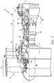
- FIG. 1 schematically illustrates a gas turbine engine 20.
- the gas turbine engine 20 as disclosed herein has a two-spool turbofan that generally incorporates a fan section 22, a compressor section 24, a combustor section 26, and a turbine section 28.
- the fan section 22 drives air along a bypass flowpath and also into a core flowpath for compression by the compressor section 24. A significant amount of thrust is provided by the bypass flow path due to the high bypass ratio.
- FIG. 1 schematically illustrates a gas turbine engine 20.
- the gas turbine engine 20 as disclosed herein has a two-spool turbofan that generally incorporates a fan section 22, a compressor section 24, a combustor section 26, and a turbine section 28.
- the fan section 22 drives air along a bypass flowpath and also into a core flowpath for compression by the compressor section 24. A significant amount of thrust is provided by the bypass flow path due to the high bypass ratio.
- FIG. 1 schematically illustrates a gas turbine engine 20.
- the gas turbine engine 20 as disclosed herein has
- the gas turbine engine 20 in this example includes a low spool 30 and a high spool 32 mounted for rotation around an engine central longitudinal axis A relative to an engine case structure 36 via several bearing compartments 38.
- the low spool 30 generally includes an inner shaft 40 that interconnects a fan 42, a low pressure compressor (“LPC”) 44, and a low pressure turbine (“LPT”) 46.
- the inner shaft 40 drives the fan 42 either directly, or through a geared architecture 48 to drive the fan 42 at a lower rotational speed than the low spool 30.
- An exemplary reduction transmission is an epicyclic transmission, such as a planetary, or star gear system.
- the high spool 32 includes an outer shaft 50 that interconnects a high pressure compressor (“HPC”) 52 and a high pressure turbine (“HPT”) 54.
- a combustor 56 is arranged between the HPC 52 and the HPT 54. The core airflow is compressed by the LPC 44, then the HPC 52, mixed with fuel and burned in the combustor 56, then expanded over the HPT 54 and the LPT 46 to rotationally drive the respective low spool 30 and high spool 32 in response to the expansion.
- a full ring shroud assembly 60 within the engine case structure 36 supports a blade outer air seal assembly 62.
- the assembly 62 includes a multiple of segments 64 proximate to a rotor blade assembly 66.
- the blade outer air seal assemblies 62 are axially disposed between a forward stationary vane ring 68 and an aft stationary vane ring 70.
- Each vane ring 68, 70 includes an array of vanes 72, 74 that extend between a respective inner vane support 76, 78 and an outer vane support 80, 82.
- the inner vane support 76, 78 and the outer vane supports 80, 82 are attached to the engine case structure 36.
- the rotor blade assembly 66 includes an array of blades 84 circumferentially disposed around a disk 86.
- Each blade 84 includes a root 88, a platform 90 and an airfoil 92.
- the blade roots 88 are received within the disk 86 such that the airfoils 92 extend radially outward so that a blade tip 94 of each airfoil 92 is adjacent to the blade outer air seal assembly 62.
- Each segment 64 includes a surface 65 which is adjacent to the blade tips 94.
- the surface 65 may be formed in part by an abradable material 67 applied to the segments 64.
- the blade tips 94 rotate along a blade path to define a rub direction and may contact the abradable material 67.
- the abradable material 67 such as yttrium oxide, abrades upon contact with the rotating blade tips 94 to, for example, form a trench in the abradable material 67 to better seal with the blade tips 94 under some operational conditions.
- a wear indicator 100 is attached to the surface 65.
- the wear indicator 100 is located within the blade clearance "L" between the blade tips 94 and the surface 65.
- Blade clearance is designed to be very small during operation for efficiency reasons, and with relatively small blades that means the cold clearance is not much larger, and so initial clearance to the wear indicator 100 will be negligible. Additionally, there is always some cold clearance in a rotor installation that experiences close-down during operation from loading, untwist, thermal growth, etc.
- the wear indicator 100 could be installed proud of the surface, or recessed to some degree into the surface or the abradeable. Although depicted in the turbine section, the wear indicator 100 may alternatively or additionally be located in other or additional sections of the gas turbine engine 20.
- the wear indicator 100 may be adhesively bonded onto the abradable material 67 to extend radially inwardly ( FIG. 4 ) from the surface 65. That is, the blade tips 94 rub the wear indicator 100 prior to contact with the surface 65 as the wear indicator 100 extends radially inwardly from the surface 65.
- the wear indicator 100 is embedded ( FIG. 5 ) at least partially within the abradable material 67 to be flush with the surface 65.
- multiple wear indicators 100 may be located to measure blade clearance at multiple circumferential positons. In one example, over one hundred wear indicators 100 may be attached around a single rotor blade assembly 66.
- each wear indicator 100 includes a capacitor 102 formed of a multiple of layers 104 that define a height H1 ( FIG. 4 ) transverse to the rub direction.
- the height H1 ( FIG. 4 ) of the capacitor 102 in one example, may be 0.05 inches (1.3 mm).
- Each layer 104 is separated by an insulator 106 and includes a first plate 108, a second plate 110, and a dielectric 112 between the first plate 108 and the second plate 110.
- the first plate 108 is connected to a first conductor 114 and the second plate 110 is connected to a second conductor 116.
- the multiple of layers 104 may be of various configurations such as a coiled arrangement, a linear arrangement, or other arrangement that are encapsulated in a potting material 118.
- the coiled embodiment was chosen for a higher capacitive density for circumferential surface area, however, various capacitor geometries that have a definable change in capacitance with changes in amount of remaining material can alternatively or additionally be used such as a single parallel plate capacitor with the plates perpendicular to the circumferential tangent (on end in the radial direction).
- the potting material 118 ( FIG. 4 ) may be formed in a conical frustum shape ( FIG. 7 ) as such a shape is aerodynamic and facilitates clean shearing by the blade tips 94.
- the potting material 118 may be manufactured of a non-conductive material that insulates the capacitor 102 and withstands the high temperatures within the gas turbine engine.
- the type of potting material 118 may be specifically selected in relation to the material from which the blades 84 are manufactured.
- the potting material 118 may be a boron nitride material for use with a relatively soft compressor blade material.
- the potting material 118 may be an alumina material or other ceramic material for a relatively hard turbine blade material.
- the first conductor 114 and the second conductor 116 are in communication with a controller 130.
- the controller 130 is operable to determine the change in capacitance and thus a corresponding amount of material removed from the wear indicator 100.
- the controller 130 may include a processor, a memory, and an interface.
- the processor can be any type or combination of computer processors, such as a microprocessor, microcontroller, digital signal processor, application specific integrated circuit, programmable logic device, and/or field programmable gate array.
- the memory may include any type of computer readable medium that stores the data and control algorithms described herein such as a non-transitory computer readable storage medium tangibly embodied in, for instance, as firmware, or operably connected to, one or more wear indicators 100 via the interface. Other operational software for the processor may also be stored in the memory.
- a method 200 for detecting blade clearance in the gas turbine engine is disclosed in terms of block diagrams.
- the wear indicator 100 is attached (210) to the surface 65 of the gas turbine engine adjacent the array of blades 84 of the gas turbine engine.
- reference measurements may be acquired by a measurement device such as a coordinate measuring machine which is operable to measure physical geometric characteristics.
- a reference measurement may be acquired between the wear indicator 100 and the engine central longitudinal axis A ( FIG 1 and 2 ).
- a reference measurement may also be acquired from the engine central longitudinal axis A to one or more of the blade tips 94.
- a reference measurement may also be acquired from the engine central longitudinal axis A to the surface 65.
- the wear indicator 100 and/or the abradable material 67 may be pre-rubbed to provide an initial desired clearance between the blade tips 94 and the wear indicator 100 and/or the abradable material 67.
- numerous wear indicators 100 may be attached within a single stage, each may originally have a slightly different pre-rub installed distance from the engine central longitudinal axis A.
- a first capacitance of the wear indicator is measured (214).
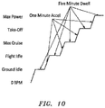
- the first capacitance measurement may be taken prior to engine operation, after the pre-rub machining, at ground idle, at flight idle, at max cruise, at take-off, at max power, or at any other time during an engine run ( FIG. 10 ).
- the measurement may be taken during, for example, flight cycles and ground tests in aerospace engines, power generation, and other turbomachinery applications.
- a second capacitance of the wear indicator is measured (216) subsequent to the first measurement.
- Operation of the wear indicator 100 provides multiple clearance/closedown measurements at multiple times during an engine run flight cycle that are minimally affected by temperature change, not only after teardown.
- the second capacitance measurement may be taken at ground idle, at flight idle, at max cruise, at take-off, at max power, or at any other time during an engine run flight cycle ( FIG. 10 ).
- the wear indicator 100 can be used as in situ calibration of non-contact tip-clearance measurement systems and can also be used to characterize as-built production engines as a production quality/performance test.
- a change in capacitance between the first and second capacitance is determined (218).
- the capacitor 102 is sheared off upon passage of the blade tips 94 which reduces the height of the capacitor 102 from, for example, H1 ( FIG. 4 ) to H2 ( FIG. 8 ).
- the height reduction from H1 ( FIG. 4 ) to H2 ( FIG. 8 ) necessarily reduces the effective area of the capacitor 102 and thus changes the capacitance thereof.
- the change in capacitance may be determined on board the engine by the controller 130 or communicated off board the engine for analysis.
- One device operable to provide such resolution is the E4981A capacitance meter from Keysight Technologies of Englewood, Colorado, United States.
- the amount of material removed from the wear indicator 100 is determined (220).
- a 35 picofarad (pF) change of capacitance corresponds to 0.001 inches (2.54 x 10 -2 mm) of material removed from the wear indicator 100 ( FIG. 11 ).
- the amount of material removed from the wear indicator 100 may then be used to determine (222) a clearance between the blade tips 94 and the surface 65.
- the clearance data could be used to identify operational performance at several engine operating conditions and also for one-time over-rub warning. This leads to the potential for correlation of the build processes to facilitate improved manufacturing processes.
Landscapes
- Engineering & Computer Science (AREA)
- Mechanical Engineering (AREA)
- General Engineering & Computer Science (AREA)
- Physics & Mathematics (AREA)
- General Physics & Mathematics (AREA)
- Chemical & Material Sciences (AREA)
- Combustion & Propulsion (AREA)
- Turbine Rotor Nozzle Sealing (AREA)
- Measurement Of Length, Angles, Or The Like Using Electric Or Magnetic Means (AREA)
Applications Claiming Priority (1)
| Application Number | Priority Date | Filing Date | Title |
|---|---|---|---|
| US15/846,859 US10731506B2 (en) | 2017-12-19 | 2017-12-19 | Capacitance based wear indicator |
Publications (2)
| Publication Number | Publication Date |
|---|---|
| EP3502425A1 true EP3502425A1 (fr) | 2019-06-26 |
| EP3502425B1 EP3502425B1 (fr) | 2023-08-23 |
Family
ID=64746262
Family Applications (1)
| Application Number | Title | Priority Date | Filing Date |
|---|---|---|---|
| EP18214224.0A Active EP3502425B1 (fr) | 2017-12-19 | 2018-12-19 | Indicateur d'usure à base de capacité et procédé de mesure d'éloignement |
Country Status (2)
| Country | Link |
|---|---|
| US (1) | US10731506B2 (fr) |
| EP (1) | EP3502425B1 (fr) |
Cited By (1)
| Publication number | Priority date | Publication date | Assignee | Title |
|---|---|---|---|---|
| WO2021209707A1 (fr) * | 2020-04-15 | 2021-10-21 | Safran Aircraft Engines | Turbine pour une turbomachine |
Families Citing this family (5)
| Publication number | Priority date | Publication date | Assignee | Title |
|---|---|---|---|---|
| US11549797B2 (en) * | 2018-10-26 | 2023-01-10 | Deere & Company | Device for detecting wear of replaceable components |
| US11002637B2 (en) * | 2018-11-30 | 2021-05-11 | Raytheon Technologies Corporation | Embedded wireless and passive sensor |
| WO2022146807A1 (fr) * | 2020-12-31 | 2022-07-07 | Lord Corporation | Système de détection pour détecter des événements d'abrasion ou l'usure d'un revêtement abradable dans une turbomachine |
| US11692490B2 (en) * | 2021-05-26 | 2023-07-04 | Doosan Heavy Industries & Construction Co., Ltd. | Gas turbine inner shroud with abradable surface feature |
| US20250084770A1 (en) * | 2023-09-11 | 2025-03-13 | Rtx Corporation | Proximity measurement between seal elements of a gas turbine engine |
Citations (5)
| Publication number | Priority date | Publication date | Assignee | Title |
|---|---|---|---|---|
| US20050158511A1 (en) * | 2002-09-23 | 2005-07-21 | Siemens Westinghouse Power Corporation | Wear monitoring system with embedded conductors |
| WO2005083411A1 (fr) * | 2004-02-27 | 2005-09-09 | Mcgill University | Procede et dispositif de detection d'usure |
| US20060056959A1 (en) * | 2002-09-23 | 2006-03-16 | Siemens Westinghouse Power Corporation | Apparatus and method of monitoring operating parameters of a gas turbine |
| GB2449709A (en) * | 2007-06-02 | 2008-12-03 | Rolls Royce Plc | Method and apparatus for determining a clearance between relatively movable components |
| US20100117859A1 (en) * | 2004-06-21 | 2010-05-13 | Mitchell David J | Apparatus and Method of Monitoring Operating Parameters of a Gas Turbine |
Family Cites Families (10)
| Publication number | Priority date | Publication date | Assignee | Title |
|---|---|---|---|---|
| US7026909B2 (en) * | 2003-12-12 | 2006-04-11 | Rosemount Aerospace, Inc. | Housing for temperature sensing assemblies in a thermometer |
| US8177474B2 (en) | 2007-06-26 | 2012-05-15 | General Electric Company | System and method for turbine engine clearance control with rub detection |
| DE102007051027A1 (de) | 2007-10-25 | 2009-04-30 | Mtu Aero Engines Gmbh | Strömungsmaschine, Spaltmesssystem und Verfahren zum Ermitteln eines Rotorspaltes |
| US8132467B2 (en) * | 2008-09-15 | 2012-03-13 | Siemens Energy, Inc. | Apparatus and method for monitoring wear of components |
| US8684669B2 (en) * | 2011-02-15 | 2014-04-01 | Siemens Energy, Inc. | Turbine tip clearance measurement |
| US8922311B2 (en) * | 2012-09-25 | 2014-12-30 | Hamilton Sundstrand Corporation | Electrical inductor assembly and method of cooling an electrical inductor assembly |
| US9518850B2 (en) | 2012-09-28 | 2016-12-13 | United Technologies Corporation | Embedded cap probe |
| US9395171B2 (en) * | 2012-11-05 | 2016-07-19 | Siemens Energy, Inc. | Capacitive sensor with orthogonal fields |
| CN105588509A (zh) | 2015-12-16 | 2016-05-18 | 中国航空工业集团公司沈阳发动机设计研究所 | 一种叶尖间隙动态测量系统 |
| US10760445B2 (en) * | 2017-08-03 | 2020-09-01 | Raytheon Technologies Corporation | Electrical resistance wear indicator |
-
2017
- 2017-12-19 US US15/846,859 patent/US10731506B2/en active Active
-
2018
- 2018-12-19 EP EP18214224.0A patent/EP3502425B1/fr active Active
Patent Citations (5)
| Publication number | Priority date | Publication date | Assignee | Title |
|---|---|---|---|---|
| US20050158511A1 (en) * | 2002-09-23 | 2005-07-21 | Siemens Westinghouse Power Corporation | Wear monitoring system with embedded conductors |
| US20060056959A1 (en) * | 2002-09-23 | 2006-03-16 | Siemens Westinghouse Power Corporation | Apparatus and method of monitoring operating parameters of a gas turbine |
| WO2005083411A1 (fr) * | 2004-02-27 | 2005-09-09 | Mcgill University | Procede et dispositif de detection d'usure |
| US20100117859A1 (en) * | 2004-06-21 | 2010-05-13 | Mitchell David J | Apparatus and Method of Monitoring Operating Parameters of a Gas Turbine |
| GB2449709A (en) * | 2007-06-02 | 2008-12-03 | Rolls Royce Plc | Method and apparatus for determining a clearance between relatively movable components |
Cited By (4)
| Publication number | Priority date | Publication date | Assignee | Title |
|---|---|---|---|---|
| WO2021209707A1 (fr) * | 2020-04-15 | 2021-10-21 | Safran Aircraft Engines | Turbine pour une turbomachine |
| FR3109402A1 (fr) * | 2020-04-15 | 2021-10-22 | Safran Aircraft Engines | Turbine pour une turbomachine |
| CN115443370A (zh) * | 2020-04-15 | 2022-12-06 | 赛峰飞机发动机公司 | 用于涡轮发动机的涡轮 |
| US11879341B2 (en) | 2020-04-15 | 2024-01-23 | Safran Aircraft Engines | Turbine for a turbine engine |
Also Published As
| Publication number | Publication date |
|---|---|
| US10731506B2 (en) | 2020-08-04 |
| EP3502425B1 (fr) | 2023-08-23 |
| US20190186285A1 (en) | 2019-06-20 |
Similar Documents
| Publication | Publication Date | Title |
|---|---|---|
| EP3502425B1 (fr) | Indicateur d'usure à base de capacité et procédé de mesure d'éloignement | |
| EP3660281B1 (fr) | Système de surveillance d'usure, moteur à turbine à gaz et procédé pour former un système de surveillance d'usure | |
| US10436732B2 (en) | Near full hoop electrical axial shift wear indication sensor | |
| US10775269B2 (en) | Blade health inspection using an excitation actuator and vibration sensor | |
| US20140007591A1 (en) | Advanced tip-timing measurement blade mode identification | |
| US9879557B2 (en) | Inner stage turbine seal for gas turbine engine | |
| US9939247B1 (en) | Embedded sensor for in-situ monitoring of blade tip incursion | |
| EP3473817B1 (fr) | Système de mesure de performance d'entrée pour moteur à turbine à gaz | |
| EP3438636B1 (fr) | Indicateur d'usure de résistance électrique | |
| US9279336B2 (en) | High temperature split-face probe | |
| US9726044B2 (en) | Consumable assembly mistake proofing tool for a gas turbine engine | |
| EP2984291B1 (fr) | Segment tuyère d'une turbine à gaz | |
| US20160146601A1 (en) | Throat area calculation for a section of a gas turbine engine | |
| US10641596B2 (en) | Systems and methods for pseudo-triaxial capacitance probe assemblies | |
| US10100652B2 (en) | Cover plate for a rotor assembly of a gas turbine engine | |
| EP2885520B1 (fr) | Composant pour un moteur à turbine à gaz et procédé de refroidissement associé | |
| US9810088B2 (en) | Floating blade outer air seal assembly for gas turbine engine | |
| EP2890878B1 (fr) | Joint d'étanchéité à l'air externe d'aube | |
| US12421866B2 (en) | Anti-rotation feature for instrumentation of gas turbine engine | |
| EP4520926A1 (fr) | Mesure d' espace entre des éléments d'étanchéité d'un moteur à turbine à gaz | |
| US20170107841A1 (en) | Blade outer air seal |
Legal Events
| Date | Code | Title | Description |
|---|---|---|---|
| PUAI | Public reference made under article 153(3) epc to a published international application that has entered the european phase |
Free format text: ORIGINAL CODE: 0009012 |
|
| STAA | Information on the status of an ep patent application or granted ep patent |
Free format text: STATUS: THE APPLICATION HAS BEEN PUBLISHED |
|
| AK | Designated contracting states |
Kind code of ref document: A1 Designated state(s): AL AT BE BG CH CY CZ DE DK EE ES FI FR GB GR HR HU IE IS IT LI LT LU LV MC MK MT NL NO PL PT RO RS SE SI SK SM TR |
|
| AX | Request for extension of the european patent |
Extension state: BA ME |
|
| STAA | Information on the status of an ep patent application or granted ep patent |
Free format text: STATUS: REQUEST FOR EXAMINATION WAS MADE |
|
| 17P | Request for examination filed |
Effective date: 20200102 |
|
| RBV | Designated contracting states (corrected) |
Designated state(s): AL AT BE BG CH CY CZ DE DK EE ES FI FR GB GR HR HU IE IS IT LI LT LU LV MC MK MT NL NO PL PT RO RS SE SI SK SM TR |
|
| STAA | Information on the status of an ep patent application or granted ep patent |
Free format text: STATUS: EXAMINATION IS IN PROGRESS |
|
| 17Q | First examination report despatched |
Effective date: 20210204 |
|
| RAP1 | Party data changed (applicant data changed or rights of an application transferred) |
Owner name: RAYTHEON TECHNOLOGIES CORPORATION |
|
| GRAP | Despatch of communication of intention to grant a patent |
Free format text: ORIGINAL CODE: EPIDOSNIGR1 |
|
| STAA | Information on the status of an ep patent application or granted ep patent |
Free format text: STATUS: GRANT OF PATENT IS INTENDED |
|
| INTG | Intention to grant announced |
Effective date: 20230306 |
|
| GRAS | Grant fee paid |
Free format text: ORIGINAL CODE: EPIDOSNIGR3 |
|
| GRAA | (expected) grant |
Free format text: ORIGINAL CODE: 0009210 |
|
| STAA | Information on the status of an ep patent application or granted ep patent |
Free format text: STATUS: THE PATENT HAS BEEN GRANTED |
|
| AK | Designated contracting states |
Kind code of ref document: B1 Designated state(s): AL AT BE BG CH CY CZ DE DK EE ES FI FR GB GR HR HU IE IS IT LI LT LU LV MC MK MT NL NO PL PT RO RS SE SI SK SM TR |
|
| REG | Reference to a national code |
Ref country code: GB Ref legal event code: FG4D |
|
| REG | Reference to a national code |
Ref country code: CH Ref legal event code: EP |
|
| REG | Reference to a national code |
Ref country code: IE Ref legal event code: FG4D |
|
| REG | Reference to a national code |
Ref country code: DE Ref legal event code: R096 Ref document number: 602018055851 Country of ref document: DE |
|
| RAP4 | Party data changed (patent owner data changed or rights of a patent transferred) |
Owner name: RTX CORPORATION |
|
| REG | Reference to a national code |
Ref country code: LT Ref legal event code: MG9D |
|
| REG | Reference to a national code |
Ref country code: NL Ref legal event code: MP Effective date: 20230823 |
|
| REG | Reference to a national code |
Ref country code: AT Ref legal event code: MK05 Ref document number: 1602811 Country of ref document: AT Kind code of ref document: T Effective date: 20230823 |
|
| PG25 | Lapsed in a contracting state [announced via postgrant information from national office to epo] |
Ref country code: GR Free format text: LAPSE BECAUSE OF FAILURE TO SUBMIT A TRANSLATION OF THE DESCRIPTION OR TO PAY THE FEE WITHIN THE PRESCRIBED TIME-LIMIT Effective date: 20231124 |
|
| PG25 | Lapsed in a contracting state [announced via postgrant information from national office to epo] |
Ref country code: IS Free format text: LAPSE BECAUSE OF FAILURE TO SUBMIT A TRANSLATION OF THE DESCRIPTION OR TO PAY THE FEE WITHIN THE PRESCRIBED TIME-LIMIT Effective date: 20231223 |
|
| PG25 | Lapsed in a contracting state [announced via postgrant information from national office to epo] |
Ref country code: SE Free format text: LAPSE BECAUSE OF FAILURE TO SUBMIT A TRANSLATION OF THE DESCRIPTION OR TO PAY THE FEE WITHIN THE PRESCRIBED TIME-LIMIT Effective date: 20230823 Ref country code: RS Free format text: LAPSE BECAUSE OF FAILURE TO SUBMIT A TRANSLATION OF THE DESCRIPTION OR TO PAY THE FEE WITHIN THE PRESCRIBED TIME-LIMIT Effective date: 20230823 Ref country code: PT Free format text: LAPSE BECAUSE OF FAILURE TO SUBMIT A TRANSLATION OF THE DESCRIPTION OR TO PAY THE FEE WITHIN THE PRESCRIBED TIME-LIMIT Effective date: 20231226 Ref country code: NO Free format text: LAPSE BECAUSE OF FAILURE TO SUBMIT A TRANSLATION OF THE DESCRIPTION OR TO PAY THE FEE WITHIN THE PRESCRIBED TIME-LIMIT Effective date: 20231123 Ref country code: NL Free format text: LAPSE BECAUSE OF FAILURE TO SUBMIT A TRANSLATION OF THE DESCRIPTION OR TO PAY THE FEE WITHIN THE PRESCRIBED TIME-LIMIT Effective date: 20230823 Ref country code: LV Free format text: LAPSE BECAUSE OF FAILURE TO SUBMIT A TRANSLATION OF THE DESCRIPTION OR TO PAY THE FEE WITHIN THE PRESCRIBED TIME-LIMIT Effective date: 20230823 Ref country code: LT Free format text: LAPSE BECAUSE OF FAILURE TO SUBMIT A TRANSLATION OF THE DESCRIPTION OR TO PAY THE FEE WITHIN THE PRESCRIBED TIME-LIMIT Effective date: 20230823 Ref country code: IS Free format text: LAPSE BECAUSE OF FAILURE TO SUBMIT A TRANSLATION OF THE DESCRIPTION OR TO PAY THE FEE WITHIN THE PRESCRIBED TIME-LIMIT Effective date: 20231223 Ref country code: HR Free format text: LAPSE BECAUSE OF FAILURE TO SUBMIT A TRANSLATION OF THE DESCRIPTION OR TO PAY THE FEE WITHIN THE PRESCRIBED TIME-LIMIT Effective date: 20230823 Ref country code: GR Free format text: LAPSE BECAUSE OF FAILURE TO SUBMIT A TRANSLATION OF THE DESCRIPTION OR TO PAY THE FEE WITHIN THE PRESCRIBED TIME-LIMIT Effective date: 20231124 Ref country code: FI Free format text: LAPSE BECAUSE OF FAILURE TO SUBMIT A TRANSLATION OF THE DESCRIPTION OR TO PAY THE FEE WITHIN THE PRESCRIBED TIME-LIMIT Effective date: 20230823 Ref country code: AT Free format text: LAPSE BECAUSE OF FAILURE TO SUBMIT A TRANSLATION OF THE DESCRIPTION OR TO PAY THE FEE WITHIN THE PRESCRIBED TIME-LIMIT Effective date: 20230823 |
|
| PG25 | Lapsed in a contracting state [announced via postgrant information from national office to epo] |
Ref country code: PL Free format text: LAPSE BECAUSE OF FAILURE TO SUBMIT A TRANSLATION OF THE DESCRIPTION OR TO PAY THE FEE WITHIN THE PRESCRIBED TIME-LIMIT Effective date: 20230823 |
|
| PG25 | Lapsed in a contracting state [announced via postgrant information from national office to epo] |
Ref country code: ES Free format text: LAPSE BECAUSE OF FAILURE TO SUBMIT A TRANSLATION OF THE DESCRIPTION OR TO PAY THE FEE WITHIN THE PRESCRIBED TIME-LIMIT Effective date: 20230823 |
|
| PG25 | Lapsed in a contracting state [announced via postgrant information from national office to epo] |
Ref country code: SM Free format text: LAPSE BECAUSE OF FAILURE TO SUBMIT A TRANSLATION OF THE DESCRIPTION OR TO PAY THE FEE WITHIN THE PRESCRIBED TIME-LIMIT Effective date: 20230823 Ref country code: RO Free format text: LAPSE BECAUSE OF FAILURE TO SUBMIT A TRANSLATION OF THE DESCRIPTION OR TO PAY THE FEE WITHIN THE PRESCRIBED TIME-LIMIT Effective date: 20230823 Ref country code: ES Free format text: LAPSE BECAUSE OF FAILURE TO SUBMIT A TRANSLATION OF THE DESCRIPTION OR TO PAY THE FEE WITHIN THE PRESCRIBED TIME-LIMIT Effective date: 20230823 Ref country code: EE Free format text: LAPSE BECAUSE OF FAILURE TO SUBMIT A TRANSLATION OF THE DESCRIPTION OR TO PAY THE FEE WITHIN THE PRESCRIBED TIME-LIMIT Effective date: 20230823 Ref country code: DK Free format text: LAPSE BECAUSE OF FAILURE TO SUBMIT A TRANSLATION OF THE DESCRIPTION OR TO PAY THE FEE WITHIN THE PRESCRIBED TIME-LIMIT Effective date: 20230823 Ref country code: CZ Free format text: LAPSE BECAUSE OF FAILURE TO SUBMIT A TRANSLATION OF THE DESCRIPTION OR TO PAY THE FEE WITHIN THE PRESCRIBED TIME-LIMIT Effective date: 20230823 Ref country code: SK Free format text: LAPSE BECAUSE OF FAILURE TO SUBMIT A TRANSLATION OF THE DESCRIPTION OR TO PAY THE FEE WITHIN THE PRESCRIBED TIME-LIMIT Effective date: 20230823 |
|
| REG | Reference to a national code |
Ref country code: DE Ref legal event code: R097 Ref document number: 602018055851 Country of ref document: DE |
|
| PG25 | Lapsed in a contracting state [announced via postgrant information from national office to epo] |
Ref country code: IT Free format text: LAPSE BECAUSE OF FAILURE TO SUBMIT A TRANSLATION OF THE DESCRIPTION OR TO PAY THE FEE WITHIN THE PRESCRIBED TIME-LIMIT Effective date: 20230823 |
|
| PLBE | No opposition filed within time limit |
Free format text: ORIGINAL CODE: 0009261 |
|
| STAA | Information on the status of an ep patent application or granted ep patent |
Free format text: STATUS: NO OPPOSITION FILED WITHIN TIME LIMIT |
|
| 26N | No opposition filed |
Effective date: 20240524 |
|
| PG25 | Lapsed in a contracting state [announced via postgrant information from national office to epo] |
Ref country code: SI Free format text: LAPSE BECAUSE OF FAILURE TO SUBMIT A TRANSLATION OF THE DESCRIPTION OR TO PAY THE FEE WITHIN THE PRESCRIBED TIME-LIMIT Effective date: 20230823 |
|
| REG | Reference to a national code |
Ref country code: CH Ref legal event code: PL |
|
| PG25 | Lapsed in a contracting state [announced via postgrant information from national office to epo] |
Ref country code: LU Free format text: LAPSE BECAUSE OF NON-PAYMENT OF DUE FEES Effective date: 20231219 |
|
| PG25 | Lapsed in a contracting state [announced via postgrant information from national office to epo] |
Ref country code: MC Free format text: LAPSE BECAUSE OF FAILURE TO SUBMIT A TRANSLATION OF THE DESCRIPTION OR TO PAY THE FEE WITHIN THE PRESCRIBED TIME-LIMIT Effective date: 20230823 |
|
| REG | Reference to a national code |
Ref country code: BE Ref legal event code: MM Effective date: 20231231 |
|
| PG25 | Lapsed in a contracting state [announced via postgrant information from national office to epo] |
Ref country code: MC Free format text: LAPSE BECAUSE OF FAILURE TO SUBMIT A TRANSLATION OF THE DESCRIPTION OR TO PAY THE FEE WITHIN THE PRESCRIBED TIME-LIMIT Effective date: 20230823 Ref country code: LU Free format text: LAPSE BECAUSE OF NON-PAYMENT OF DUE FEES Effective date: 20231219 |
|
| REG | Reference to a national code |
Ref country code: IE Ref legal event code: MM4A |
|
| PG25 | Lapsed in a contracting state [announced via postgrant information from national office to epo] |
Ref country code: IE Free format text: LAPSE BECAUSE OF NON-PAYMENT OF DUE FEES Effective date: 20231219 |
|
| PG25 | Lapsed in a contracting state [announced via postgrant information from national office to epo] |
Ref country code: BE Free format text: LAPSE BECAUSE OF NON-PAYMENT OF DUE FEES Effective date: 20231231 |
|
| PG25 | Lapsed in a contracting state [announced via postgrant information from national office to epo] |
Ref country code: CH Free format text: LAPSE BECAUSE OF NON-PAYMENT OF DUE FEES Effective date: 20231231 |
|
| PG25 | Lapsed in a contracting state [announced via postgrant information from national office to epo] |
Ref country code: IE Free format text: LAPSE BECAUSE OF NON-PAYMENT OF DUE FEES Effective date: 20231219 Ref country code: CH Free format text: LAPSE BECAUSE OF NON-PAYMENT OF DUE FEES Effective date: 20231231 Ref country code: BE Free format text: LAPSE BECAUSE OF NON-PAYMENT OF DUE FEES Effective date: 20231231 |
|
| PG25 | Lapsed in a contracting state [announced via postgrant information from national office to epo] |
Ref country code: BG Free format text: LAPSE BECAUSE OF FAILURE TO SUBMIT A TRANSLATION OF THE DESCRIPTION OR TO PAY THE FEE WITHIN THE PRESCRIBED TIME-LIMIT Effective date: 20230823 |
|
| PG25 | Lapsed in a contracting state [announced via postgrant information from national office to epo] |
Ref country code: BG Free format text: LAPSE BECAUSE OF FAILURE TO SUBMIT A TRANSLATION OF THE DESCRIPTION OR TO PAY THE FEE WITHIN THE PRESCRIBED TIME-LIMIT Effective date: 20230823 |
|
| PG25 | Lapsed in a contracting state [announced via postgrant information from national office to epo] |
Ref country code: CY Free format text: LAPSE BECAUSE OF FAILURE TO SUBMIT A TRANSLATION OF THE DESCRIPTION OR TO PAY THE FEE WITHIN THE PRESCRIBED TIME-LIMIT; INVALID AB INITIO Effective date: 20181219 |
|
| PG25 | Lapsed in a contracting state [announced via postgrant information from national office to epo] |
Ref country code: HU Free format text: LAPSE BECAUSE OF FAILURE TO SUBMIT A TRANSLATION OF THE DESCRIPTION OR TO PAY THE FEE WITHIN THE PRESCRIBED TIME-LIMIT; INVALID AB INITIO Effective date: 20181219 |
|
| REG | Reference to a national code |
Ref country code: DE Ref legal event code: R081 Ref document number: 602018055851 Country of ref document: DE Owner name: RTX CORPORATION (N.D.GES.D. STAATES DELAWARE),, US Free format text: FORMER OWNER: RAYTHEON TECHNOLOGIES CORPORATION, FARMINGTON, CT, US |
|
| PG25 | Lapsed in a contracting state [announced via postgrant information from national office to epo] |
Ref country code: TR Free format text: LAPSE BECAUSE OF FAILURE TO SUBMIT A TRANSLATION OF THE DESCRIPTION OR TO PAY THE FEE WITHIN THE PRESCRIBED TIME-LIMIT Effective date: 20230823 |
|
| PGFP | Annual fee paid to national office [announced via postgrant information from national office to epo] |
Ref country code: DE Payment date: 20251126 Year of fee payment: 8 |
|
| PGFP | Annual fee paid to national office [announced via postgrant information from national office to epo] |
Ref country code: GB Payment date: 20251120 Year of fee payment: 8 |
|
| PGFP | Annual fee paid to national office [announced via postgrant information from national office to epo] |
Ref country code: FR Payment date: 20251120 Year of fee payment: 8 |
|
| P01 | Opt-out of the competence of the unified patent court (upc) registered |
Free format text: CASE NUMBER: UPC_APP_0019446_3502425/2025 Effective date: 20251223 |