EP3502429B1 - Collecteur de gaz d'échappement avec élément thermoélectrique - Google Patents
Collecteur de gaz d'échappement avec élément thermoélectrique Download PDFInfo
- Publication number
- EP3502429B1 EP3502429B1 EP17209969.9A EP17209969A EP3502429B1 EP 3502429 B1 EP3502429 B1 EP 3502429B1 EP 17209969 A EP17209969 A EP 17209969A EP 3502429 B1 EP3502429 B1 EP 3502429B1
- Authority
- EP
- European Patent Office
- Prior art keywords
- exhaust gas
- gas manifold
- exhaust manifold
- thermo
- cooling
- Prior art date
- Legal status (The legal status is an assumption and is not a legal conclusion. Google has not performed a legal analysis and makes no representation as to the accuracy of the status listed.)
- Active
Links
Images



Classifications
-
- F—MECHANICAL ENGINEERING; LIGHTING; HEATING; WEAPONS; BLASTING
- F01—MACHINES OR ENGINES IN GENERAL; ENGINE PLANTS IN GENERAL; STEAM ENGINES
- F01N—GAS-FLOW SILENCERS OR EXHAUST APPARATUS FOR MACHINES OR ENGINES IN GENERAL; GAS-FLOW SILENCERS OR EXHAUST APPARATUS FOR INTERNAL-COMBUSTION ENGINES
- F01N5/00—Exhaust or silencing apparatus combined or associated with devices profiting by exhaust energy
- F01N5/02—Exhaust or silencing apparatus combined or associated with devices profiting by exhaust energy the devices using heat
- F01N5/025—Exhaust or silencing apparatus combined or associated with devices profiting by exhaust energy the devices using heat the device being thermoelectric generators
-
- F—MECHANICAL ENGINEERING; LIGHTING; HEATING; WEAPONS; BLASTING
- F01—MACHINES OR ENGINES IN GENERAL; ENGINE PLANTS IN GENERAL; STEAM ENGINES
- F01N—GAS-FLOW SILENCERS OR EXHAUST APPARATUS FOR MACHINES OR ENGINES IN GENERAL; GAS-FLOW SILENCERS OR EXHAUST APPARATUS FOR INTERNAL-COMBUSTION ENGINES
- F01N13/00—Exhaust or silencing apparatus characterised by constructional features
- F01N13/08—Other arrangements or adaptations of exhaust conduits
-
- F—MECHANICAL ENGINEERING; LIGHTING; HEATING; WEAPONS; BLASTING
- F01—MACHINES OR ENGINES IN GENERAL; ENGINE PLANTS IN GENERAL; STEAM ENGINES
- F01N—GAS-FLOW SILENCERS OR EXHAUST APPARATUS FOR MACHINES OR ENGINES IN GENERAL; GAS-FLOW SILENCERS OR EXHAUST APPARATUS FOR INTERNAL-COMBUSTION ENGINES
- F01N13/00—Exhaust or silencing apparatus characterised by constructional features
- F01N13/08—Other arrangements or adaptations of exhaust conduits
- F01N13/10—Other arrangements or adaptations of exhaust conduits of exhaust manifolds
-
- F—MECHANICAL ENGINEERING; LIGHTING; HEATING; WEAPONS; BLASTING
- F01—MACHINES OR ENGINES IN GENERAL; ENGINE PLANTS IN GENERAL; STEAM ENGINES
- F01N—GAS-FLOW SILENCERS OR EXHAUST APPARATUS FOR MACHINES OR ENGINES IN GENERAL; GAS-FLOW SILENCERS OR EXHAUST APPARATUS FOR INTERNAL-COMBUSTION ENGINES
- F01N13/00—Exhaust or silencing apparatus characterised by constructional features
- F01N13/08—Other arrangements or adaptations of exhaust conduits
- F01N13/10—Other arrangements or adaptations of exhaust conduits of exhaust manifolds
- F01N13/102—Other arrangements or adaptations of exhaust conduits of exhaust manifolds having thermal insulation
-
- F—MECHANICAL ENGINEERING; LIGHTING; HEATING; WEAPONS; BLASTING
- F01—MACHINES OR ENGINES IN GENERAL; ENGINE PLANTS IN GENERAL; STEAM ENGINES
- F01N—GAS-FLOW SILENCERS OR EXHAUST APPARATUS FOR MACHINES OR ENGINES IN GENERAL; GAS-FLOW SILENCERS OR EXHAUST APPARATUS FOR INTERNAL-COMBUSTION ENGINES
- F01N13/00—Exhaust or silencing apparatus characterised by constructional features
- F01N13/14—Exhaust or silencing apparatus characterised by constructional features having thermal insulation
-
- F—MECHANICAL ENGINEERING; LIGHTING; HEATING; WEAPONS; BLASTING
- F01—MACHINES OR ENGINES IN GENERAL; ENGINE PLANTS IN GENERAL; STEAM ENGINES
- F01N—GAS-FLOW SILENCERS OR EXHAUST APPARATUS FOR MACHINES OR ENGINES IN GENERAL; GAS-FLOW SILENCERS OR EXHAUST APPARATUS FOR INTERNAL-COMBUSTION ENGINES
- F01N13/00—Exhaust or silencing apparatus characterised by constructional features
- F01N13/14—Exhaust or silencing apparatus characterised by constructional features having thermal insulation
- F01N13/141—Double-walled exhaust pipes or housings
-
- F—MECHANICAL ENGINEERING; LIGHTING; HEATING; WEAPONS; BLASTING
- F01—MACHINES OR ENGINES IN GENERAL; ENGINE PLANTS IN GENERAL; STEAM ENGINES
- F01N—GAS-FLOW SILENCERS OR EXHAUST APPARATUS FOR MACHINES OR ENGINES IN GENERAL; GAS-FLOW SILENCERS OR EXHAUST APPARATUS FOR INTERNAL-COMBUSTION ENGINES
- F01N13/00—Exhaust or silencing apparatus characterised by constructional features
- F01N13/18—Construction facilitating manufacture, assembly, or disassembly
- F01N13/1861—Construction facilitating manufacture, assembly, or disassembly the assembly using parts formed by casting or moulding
-
- F—MECHANICAL ENGINEERING; LIGHTING; HEATING; WEAPONS; BLASTING
- F01—MACHINES OR ENGINES IN GENERAL; ENGINE PLANTS IN GENERAL; STEAM ENGINES
- F01N—GAS-FLOW SILENCERS OR EXHAUST APPARATUS FOR MACHINES OR ENGINES IN GENERAL; GAS-FLOW SILENCERS OR EXHAUST APPARATUS FOR INTERNAL-COMBUSTION ENGINES
- F01N13/00—Exhaust or silencing apparatus characterised by constructional features
- F01N13/18—Construction facilitating manufacture, assembly, or disassembly
- F01N13/1888—Construction facilitating manufacture, assembly, or disassembly the housing of the assembly consisting of two or more parts, e.g. two half-shells
-
- F—MECHANICAL ENGINEERING; LIGHTING; HEATING; WEAPONS; BLASTING
- F01—MACHINES OR ENGINES IN GENERAL; ENGINE PLANTS IN GENERAL; STEAM ENGINES
- F01N—GAS-FLOW SILENCERS OR EXHAUST APPARATUS FOR MACHINES OR ENGINES IN GENERAL; GAS-FLOW SILENCERS OR EXHAUST APPARATUS FOR INTERNAL-COMBUSTION ENGINES
- F01N3/00—Exhaust or silencing apparatus having means for purifying, rendering innocuous, or otherwise treating exhaust
- F01N3/02—Exhaust or silencing apparatus having means for purifying, rendering innocuous, or otherwise treating exhaust for cooling, or for removing solid constituents of, exhaust
-
- F—MECHANICAL ENGINEERING; LIGHTING; HEATING; WEAPONS; BLASTING
- F01—MACHINES OR ENGINES IN GENERAL; ENGINE PLANTS IN GENERAL; STEAM ENGINES
- F01N—GAS-FLOW SILENCERS OR EXHAUST APPARATUS FOR MACHINES OR ENGINES IN GENERAL; GAS-FLOW SILENCERS OR EXHAUST APPARATUS FOR INTERNAL-COMBUSTION ENGINES
- F01N3/00—Exhaust or silencing apparatus having means for purifying, rendering innocuous, or otherwise treating exhaust
- F01N3/02—Exhaust or silencing apparatus having means for purifying, rendering innocuous, or otherwise treating exhaust for cooling, or for removing solid constituents of, exhaust
- F01N3/04—Exhaust or silencing apparatus having means for purifying, rendering innocuous, or otherwise treating exhaust for cooling, or for removing solid constituents of, exhaust using liquids
- F01N3/043—Exhaust or silencing apparatus having means for purifying, rendering innocuous, or otherwise treating exhaust for cooling, or for removing solid constituents of, exhaust using liquids without contact between liquid and exhaust gases
- F01N3/046—Exhaust manifolds with cooling jacket
-
- F—MECHANICAL ENGINEERING; LIGHTING; HEATING; WEAPONS; BLASTING
- F02—COMBUSTION ENGINES; HOT-GAS OR COMBUSTION-PRODUCT ENGINE PLANTS
- F02G—HOT GAS OR COMBUSTION-PRODUCT POSITIVE-DISPLACEMENT ENGINE PLANTS; USE OF WASTE HEAT OF COMBUSTION ENGINES; NOT OTHERWISE PROVIDED FOR
- F02G5/00—Profiting from waste heat of combustion engines, not otherwise provided for
- F02G5/02—Profiting from waste heat of exhaust gases
- F02G5/04—Profiting from waste heat of exhaust gases in combination with other waste heat from combustion engines
-
- H—ELECTRICITY
- H10—SEMICONDUCTOR DEVICES; ELECTRIC SOLID-STATE DEVICES NOT OTHERWISE PROVIDED FOR
- H10N—ELECTRIC SOLID-STATE DEVICES NOT OTHERWISE PROVIDED FOR
- H10N10/00—Thermoelectric devices comprising a junction of dissimilar materials, i.e. devices exhibiting Seebeck or Peltier effects
- H10N10/10—Thermoelectric devices comprising a junction of dissimilar materials, i.e. devices exhibiting Seebeck or Peltier effects operating with only the Peltier or Seebeck effects
- H10N10/13—Thermoelectric devices comprising a junction of dissimilar materials, i.e. devices exhibiting Seebeck or Peltier effects operating with only the Peltier or Seebeck effects characterised by the heat-exchanging means at the junction
-
- F—MECHANICAL ENGINEERING; LIGHTING; HEATING; WEAPONS; BLASTING
- F01—MACHINES OR ENGINES IN GENERAL; ENGINE PLANTS IN GENERAL; STEAM ENGINES
- F01N—GAS-FLOW SILENCERS OR EXHAUST APPARATUS FOR MACHINES OR ENGINES IN GENERAL; GAS-FLOW SILENCERS OR EXHAUST APPARATUS FOR INTERNAL-COMBUSTION ENGINES
- F01N2240/00—Combination or association of two or more different exhaust treating devices, or of at least one such device with an auxiliary device, not covered by indexing codes F01N2230/00 or F01N2250/00, one of the devices being
- F01N2240/04—Combination or association of two or more different exhaust treating devices, or of at least one such device with an auxiliary device, not covered by indexing codes F01N2230/00 or F01N2250/00, one of the devices being an electric, e.g. electrostatic, device other than a heater
-
- Y—GENERAL TAGGING OF NEW TECHNOLOGICAL DEVELOPMENTS; GENERAL TAGGING OF CROSS-SECTIONAL TECHNOLOGIES SPANNING OVER SEVERAL SECTIONS OF THE IPC; TECHNICAL SUBJECTS COVERED BY FORMER USPC CROSS-REFERENCE ART COLLECTIONS [XRACs] AND DIGESTS
- Y02—TECHNOLOGIES OR APPLICATIONS FOR MITIGATION OR ADAPTATION AGAINST CLIMATE CHANGE
- Y02T—CLIMATE CHANGE MITIGATION TECHNOLOGIES RELATED TO TRANSPORTATION
- Y02T10/00—Road transport of goods or passengers
- Y02T10/10—Internal combustion engine [ICE] based vehicles
- Y02T10/12—Improving ICE efficiencies
Definitions
- the invention relates to an exhaust manifold with a thermoelectric element for utilizing the waste heat of the internal combustion engine, including an exhaust manifold preferably made of cast material, at least one thermoelectric element, the thermoelectric element preferably being designed as a plate and the thermoelectric element due to the temperature difference occurring between one side and the opposite Side generates an electrical voltage, wherein at least one thermoelectric element is arranged on at least one exhaust manifold side.
- thermoelectric elements which use the waste heat from the internal combustion engine to generate additional energy. From the prior art, such elements are mostly used in the area of the exhaust system. Such thermoelectric elements make economic sense only when there is a high temperature difference between one side of the element and the other side of the element since this generates a voltage. A disadvantage of thermoelectric elements which are fastened in the exhaust area is that the temperature difference is too small to generate energy in such a way that it makes economic sense.
- the US 2016/012592 A1 discloses a generator for an internal combustion engine, wherein a plurality of thermoelectric modules are arranged on a thermal protection covering the exhaust manifold.
- thermoelectric modules are not acted upon directly by the maximum temperature prevailing in the exhaust manifold, but are isolated from the waste heat of the internal combustion engine by the thermal insulation on which they are attached, and therefore no maximum temperature difference in the thermoelectric element between the the motor facing and the side adjacent to the cooling element is reached.
- the EP 2 489 846 A1 discloses an exhaust manifold with a thermoelectric element and a cooling element, the exhaust manifold and the cooling element being separate parts.
- the cooling element is designed as a sheet metal part.
- the WO 2011/045659 A1 shows an exhaust manifold with a thermoelectric element and a cooling element, wherein the cooling element is designed as a cast part.
- the exhaust manifold and the cooling element are designed as a single component.
- thermoelectric element for utilizing the waste heat of the internal combustion engine
- this object is achieved in that a cooling element is arranged on the thermoelectric element on the side facing away from the exhaust manifold, the cooling element having at least one cooling channel, the cooling channel serving to flow through a fluid.
- the present invention relates to an exhaust manifold with at least one thermoelectric element for using the waste heat of the internal combustion engine.
- the exhaust manifold according to the invention with a thermoelectric element includes an exhaust manifold preferably consisting of cast material, particularly preferably made of cast steel or iron, wherein an exhaust manifold made of sheet metal or other materials is also conceivable, at least one thermoelectric element, the thermoelectric element preferably being designed as a plate, and that thermoelectric element generated by the occurring temperature difference between one side of the plate and the opposite side of the plate, the thermoelectric element can also have other designs such as plates.
- At least one thermoelectric element is arranged on the exhaust manifold side, exhaust manifold side being understood to mean the outer sides such as the top and bottom of the exhaust manifold as well as the front side which connects the top and bottom and is preferably designed as a radius.
- a cooling element is arranged on each thermoelectric element on the side facing away from the exhaust manifold, the cooling element having at least one cooling duct, the cooling duct serving to flow through a fluid.
- the exhaust manifold and the cooling element are designed as separate parts. This also enables the separate production of the exhaust manifold and the cooling element and that different materials can be used that are specifically adapted to the requirements. Because the Parts that are not connected to one another or are not designed as one part can be prevented from creating a thermal bridge in which the heat of the exhaust manifold is transferred to the cooling element.
- a cooling element preferably extends over the entire width of an exhaust manifold side, that is, preferably over the entire width of the exhaust manifold top and / or the exhaust manifold underside and / or the exhaust manifold front, which means that the cooling element extends over all exhaust gas inlets.
- a cooling element preferably also extends over the entire length of an exhaust manifold side, preferably the top of the exhaust manifold and / or the underside of the exhaust manifold, that is, along the exhaust gas inlets up to the outlet connection in which the exhaust gas inlets are brought together. This ensures optimal use of the available area of the exhaust manifold.
- the cooling element or elements are preferably designed as a one-piece, continuous element over the entire width and length. This avoids unnecessary separation points that do not result in optimal use of space and also makes it easier to attach to the exhaust manifold.
- thermoelectric element is likewise arranged on the front side, which connects the upper and lower exhaust manifold faces and is preferably designed as a radius, in which a cooling element also bears on the side facing away from the exhaust manifold. Which makes optimal use of the surface of the exhaust manifold.
- the cooling element is designed as a cast part, the cooling element being particularly preferably designed as an aluminum or magnesium die-cast part.
- the cooling element can also be designed as a milled part or sheet metal part, in which case it is formed by two half-shells in order to introduce the cooling channel, which are then assembled to form a cooling element which preferably contains a seal to seal the half-shells from one another.
- thermoelectric element on one side or the surfaces of the cooling element contact the surface of the thermoelectric element without another element or material being arranged in between.
- thermoelectric element on the side of the cooling element is optimally cooled and as a result experiences a high temperature difference between the two sides of the thermoelectric element.
- thermoelectric element In order to achieve the highest possible temperature difference between the two sides of the thermoelectric element, as mentioned above, at least one thermoelectric element or one side thereof lies directly on an exhaust manifold side.
- the side of a thermoelectric element lies directly on the outer surface of the underside of the exhaust manifold and / or the top of the exhaust manifold and / or the front of the exhaust manifold, or a preferably continuous thermoelectric element is arranged on the respective side, this ensures optimal use of the heating surface of the exhaust manifold.
- a filling element is arranged between the outer surface of the exhaust manifold side and the thermoelectric element.
- the filler element is preferably arranged between the surface of the lower side of the exhaust manifold and / or the outer surface of the upper side of the exhaust manifold and the thermoelectric element.
- the filler element is made of a highly conductive material that transfers the heat of the exhaust manifold to the thermoelectric element with as little loss as possible. It is mainly used for easier attachment of the thermoelectric element or the cooling element to the exhaust manifold.
- thermoelectric element is fastened to the cooling element, preferably by means of a fastening means. This allows a pre-assembled assembly to be formed that can be easily attached to the exhaust manifold.
- thermoelectric elements 1 The drawing shown shows a three-dimensional view of an exhaust manifold according to the invention with thermoelectric elements 1.
- thermoelectric elements and the cooling elements are attached to the bottom and top of the exhaust manifold on two sides, but of course a possible embodiment is also that of an exhaust manifold according to the invention which has the elements only at the bottom or only at the top, as well as only at the front or on all sides, that is, above, below and on the front.
- the cooling elements 4 are fastened to the exhaust manifold 2 with the aid of fastening means 12, wherein in the embodiment shown the cooling elements 4, which are each arranged on the exhaust manifold top 5 and one on the exhaust manifold bottom 6, are clamped together.
- the thermoelectric elements 3 are arranged between the cooling elements 4 and the exhaust manifold top 5 and the other cooling element 4 and the exhaust manifold bottom 6 and in 3 - 5 evident.
- the cooling elements 4 have at least one cooling channel 9 in their interior Fig. 4 and 5 shown, through which a fluid flows and so the cooling element 4 is cooled.
- the inlet and outlet openings 13, 14 are preferably located on the end faces of the cooling elements 4.
- the cooling elements 4 are designed as separate parts, which is good in the Fig. 4 and 5 can be seen.
- the exhaust manifold 2 and the cooling elements 4 can each be made of a different material that best meets the requirements.
- Fig. 2 shows the exhaust manifold according to the invention with thermoelectric elements 1 in a plan view, thus mainly the cooling element 4, which is arranged on the exhaust manifold top 5, is visible here.
- cooling element 3 extends over the entire width of the exhaust manifold 2, that is to say over all exhaust gas inlets and also over the length of the exhaust manifold, which corresponds approximately to the length of the exhaust gas inlets up to the exhaust port 15 and thus the available area to be used optimally and therefore there are no unnecessary separation points of individual cooling elements 3.
- Fig. 3 shows an exhaust manifold according to the invention with thermoelectric elements 1 in a side view.
- the thermoelectric elements 3, which are arranged between the upper side of the exhaust manifold 5 and a cooling element 4 and the lower side of the exhaust manifold 6 and a further cooling element 4, are clearly recognizable.
- the cooling elements 4 are pressed onto the exhaust manifold 2 by means of a fastening means 12, however, there are innumerable variants of attaching the cooling elements 4 to the exhaust manifold 2, the thermoelectric elements 3 still being arranged or clamped in between.
- Fig. 4 shows an exhaust manifold according to the invention with thermoelectric elements 1 in a sectional view. It can be clearly seen here that the two thermoelectric elements 3 abut the top and bottom of the exhaust manifold 5, 6. The cooling element 4 rests on the side 8 of the thermoelectric element 3 which faces away from the exhaust manifold. Because the thermoelectric element 3 bears on one side 7 against the hot exhaust manifold 2 and the other side 8 bears against the cool cooling element 4, a high voltage is generated which can be used as energy.
- Fig. 4 shows an exhaust manifold according to the invention with thermoelectric elements 1 in a sectional view. It can be clearly seen here that the two thermoelectric elements 3 abut the top and bottom of the exhaust manifold 5, 6. The cooling element 4 rests on the side 8 of the thermoelectric element 3 which faces away from the exhaust manifold. Because the thermoelectric element 3 bears on one side 7 against the hot exhaust manifold 2 and the other side 8 bears against the cool cooling element 4, a high voltage is generated which can be used as energy.
- cooling element 4 according to the invention
- a one-piece cast part to be manufactured as a milled part, which is formed by two half-shells which are joined together by means of a seal to form a cooling element 4 (not shown).
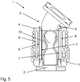
- Fig. 5 shows a further embodiment of an exhaust manifold with thermoelectric elements 1, the thermoelectric element 3 being fastened to the cooling element 4 by means of a fastening means 11, so that a preassembled assembly group is formed which can be easily fastened to the exhaust manifold 2.
- Fig. 5 also the possibility of a filling element 10, which optimizes the contact of the thermoelectric element 3 on the exhaust manifold 2 or forms a support.
- the filling element 10 preferably has a very conductive material, so that the heat of the exhaust manifold 2 can be conducted well to the side 7 of the thermoelectric element 3 and there is a high temperature difference between the side 7 facing the exhaust manifold and the side 8 facing the cooling element.
- a filler element 10 can also be used if there are no fastening means 11 for preassembling an assembly module, and such a preassembled module can also be arranged on the exhaust manifold 2 without a filler element 10.
- thermoelectric element 3 bears on the exhaust manifold side 16 or on the front side 16 of the exhaust manifold and a cooling element 4 bears on the side 8 of the thermoelectric element 3 facing away from the exhaust manifold.
- thermoelectric elements 3 and the cooling elements 4 of the various embodiments is of course also conceivable.
Landscapes
- Engineering & Computer Science (AREA)
- Chemical & Material Sciences (AREA)
- Combustion & Propulsion (AREA)
- Mechanical Engineering (AREA)
- General Engineering & Computer Science (AREA)
- Exhaust Silencers (AREA)
- Exhaust Gas After Treatment (AREA)
Claims (8)
- Collecteur de gaz d'échappement avec élément thermoélectrique (1) permettant d'exploiter la chaleur perdue du moteur à combustion interne, comprenant un collecteur de gaz d'échappement (2) de préférence en fonte, au moins un élément thermoélectrique (3), l'élément thermoélectrique (3) étant de préférence réalisé sous forme de plaque et l'élément thermoélectrique (3) générant une tension électrique par la différence de température qui se produit entre une face (7, 8) et la face opposée (7, 8), dans lequel au moins un élément thermoélectrique (3) est disposé sur au moins une face de collecteur de gaz d'échappement (5, 6, 16), un élément de refroidissement étant disposé sur l'élément thermoélectrique (3) sur la face détournée du collecteur de gaz d'échappement (8), dans lequel l'élément de refroidissement présente au moins un conduit de refroidissement (9), le conduit de refroidissement (9) servant au passage d'un fluide, caractérisé en ce que le collecteur de gaz d'échappement (2) et l'élément de refroidissement (4) sont réalisés comme des pièces séparées, l'élément de refroidissement (4) étant une pièce en fonte.
- Collecteur de gaz d'échappement (1) selon la revendication 1, caractérisé en ce que l'élément de refroidissement (4) s'étend sur toute la largeur de la face de collecteur de gaz d'échappement (5, 6, 16).
- Collecteur de gaz d'échappement (1) selon l'une quelconque des revendications 1 ou 2, caractérisé en ce que l'élément de refroidissement (4) est sur une face directement adjacente à l'élément thermoélectrique (3) pour obtenir un refroidissement direct.
- Collecteur de gaz d'échappement (1) selon l'une quelconque des revendications 1 à 3, caractérisé en ce que l'élément thermoélectrique (3) est directement adjacent à la face de collecteur de gaz d'échappement (5, 6, 16) ou à la surface extérieure de celui-ci, de préférence un seul élément thermoélectrique (3) est disposé sur la face de collecteur de gaz d'échappement (5, 6, 16), l'élément thermoélectrique (3) étant de préférence réalisé comme une pièce d'un seul tenant.
- Collecteur de gaz d'échappement (1) selon l'une quelconque des revendications 1 à 3, caractérisé en ce qu'un élément de remplissage (10) est disposé entre la surface extérieure de la face de collecteur de gaz d'échappement (5, 6, 16) et l'élément thermoélectrique (3) .
- Collecteur de gaz d'échappement (1) selon l'une quelconque des revendications 1 à 5, caractérisé en ce qu'un élément thermoélectrique (3) est disposé respectivement sur la face supérieure de collecteur de gaz d'échappement (5) et sur la face inférieure de collecteur de gaz d'échappement (6).
- Collecteur de gaz d'échappement (1) selon l'une quelconque des revendications 1 à 6, caractérisé en ce qu'un élément thermoélectrique (3) est disposé sur la face avant de collecteur de gaz d'échappement (16).
- Collecteur de gaz d'échappement (1) selon l'une quelconque des revendications 1 à 7, caractérisé en ce que l'élément thermoélectrique (3) est fixé à l'élément de refroidissement (4), de préférence à l'aide d'un moyen de fixation (11).
Priority Applications (3)
| Application Number | Priority Date | Filing Date | Title |
|---|---|---|---|
| EP17209969.9A EP3502429B1 (fr) | 2017-12-22 | 2017-12-22 | Collecteur de gaz d'échappement avec élément thermoélectrique |
| US16/224,832 US10794255B2 (en) | 2017-12-22 | 2018-12-19 | Apparatus for utilizing waste heat of an internal combustion engine |
| CN201811572250.7A CN109958518A (zh) | 2017-12-22 | 2018-12-21 | 排气歧管 |
Applications Claiming Priority (1)
| Application Number | Priority Date | Filing Date | Title |
|---|---|---|---|
| EP17209969.9A EP3502429B1 (fr) | 2017-12-22 | 2017-12-22 | Collecteur de gaz d'échappement avec élément thermoélectrique |
Publications (2)
| Publication Number | Publication Date |
|---|---|
| EP3502429A1 EP3502429A1 (fr) | 2019-06-26 |
| EP3502429B1 true EP3502429B1 (fr) | 2020-07-15 |
Family
ID=60937567
Family Applications (1)
| Application Number | Title | Priority Date | Filing Date |
|---|---|---|---|
| EP17209969.9A Active EP3502429B1 (fr) | 2017-12-22 | 2017-12-22 | Collecteur de gaz d'échappement avec élément thermoélectrique |
Country Status (3)
| Country | Link |
|---|---|
| US (1) | US10794255B2 (fr) |
| EP (1) | EP3502429B1 (fr) |
| CN (1) | CN109958518A (fr) |
Families Citing this family (3)
| Publication number | Priority date | Publication date | Assignee | Title |
|---|---|---|---|---|
| CN113756924B (zh) * | 2021-09-15 | 2024-01-12 | 南昌同岩新材科技有限公司 | 一种基于玄武岩纤维的汽车排气歧管一体化隔热装置 |
| CN117627762B (zh) * | 2023-12-19 | 2024-08-20 | 江阴信邦电子有限公司 | 一种混动汽车废热回收储能系统 |
| US12378906B1 (en) * | 2024-06-07 | 2025-08-05 | Caterpillar Inc. | Exhaust manifold assembly for internal combustion engine |
Family Cites Families (8)
| Publication number | Priority date | Publication date | Assignee | Title |
|---|---|---|---|---|
| EP1965446B1 (fr) * | 2007-02-28 | 2011-11-16 | Corning Incorporated | Module thermoélectrique en céramique-verre |
| EP2180534B1 (fr) * | 2008-10-27 | 2013-10-16 | Corning Incorporated | Dispositifs et procédés de conversion d'énergie |
| CN102365437A (zh) * | 2009-03-31 | 2012-02-29 | 雷诺卡车公司 | 包括热电装置的、用于内燃发动机设备的能量回收系统 |
| JP5781520B2 (ja) * | 2009-10-14 | 2015-09-24 | ウエスキャスト インダストリーズ インク.Wescast Industries,Inc. | 流体冷却式エキゾーストマニホールド |
| DE102011004243B4 (de) * | 2011-02-16 | 2015-02-19 | Eberspächer Exhaust Technology GmbH & Co. KG | Abgaskrümmer |
| WO2014144019A1 (fr) | 2013-03-15 | 2014-09-18 | The University Of North Carolina At Chapel Hill | Procedes, systemes et supports lisibles par ordinateur pour alignement deformable en 2d/3d en temps reel utilisant un apprentissage de mesures |
| KR101637674B1 (ko) * | 2014-09-01 | 2016-07-07 | 현대자동차주식회사 | 차량용 열전발전 장치 |
| KR101664563B1 (ko) * | 2014-10-14 | 2016-10-10 | 현대자동차주식회사 | 내연기관용 발전장치 |
-
2017
- 2017-12-22 EP EP17209969.9A patent/EP3502429B1/fr active Active
-
2018
- 2018-12-19 US US16/224,832 patent/US10794255B2/en not_active Expired - Fee Related
- 2018-12-21 CN CN201811572250.7A patent/CN109958518A/zh active Pending
Non-Patent Citations (1)
| Title |
|---|
| None * |
Also Published As
| Publication number | Publication date |
|---|---|
| EP3502429A1 (fr) | 2019-06-26 |
| CN109958518A (zh) | 2019-07-02 |
| US20190195109A1 (en) | 2019-06-27 |
| US10794255B2 (en) | 2020-10-06 |
Similar Documents
| Publication | Publication Date | Title |
|---|---|---|
| AT510857B1 (de) | Flüssigkeitsgekühlte brennkraftmaschine | |
| EP1816425B1 (fr) | Échangeur thermique de gaz d'échappement dans un agencement de recyclage des gaz d'échappement | |
| DE102017215609A1 (de) | Batteriegehäuse für eine Traktionsbatterie | |
| DE102016115352B4 (de) | Ladeluftkühlervorrichtung | |
| DE112015002074T5 (de) | Ladeluftkühler mit mehrteiligem Kunststoffgehäuse | |
| DE102009055715A1 (de) | Saugrohr mit integriertem Ladeluftkühler | |
| EP3502429B1 (fr) | Collecteur de gaz d'échappement avec élément thermoélectrique | |
| DE69921553T2 (de) | Einlasssystem für Brennkraftmaschine | |
| EP2075431B2 (fr) | Collecteur de gaz d'échappement | |
| WO2013174914A1 (fr) | Échangeur thermique pour tempérer un premier fluide à l'aide d'un second fluide | |
| DE102015200657A1 (de) | Brennkraftmaschine | |
| WO2009013332A2 (fr) | Turbocompresseur avec un carter de turbocompresseur présentant un vissage à l'aide d'un tirant d'ancrage | |
| EP0890810B1 (fr) | Véhicule automobile comprenant un échangeur de chaleur sous le plancher | |
| DE102013201109A1 (de) | Wärmeübertragungseinrichtung | |
| DE102017206201A1 (de) | Abgasrückführkühler für eine Brennkraftmaschine | |
| DE10306412B4 (de) | Abgasanlage einer lambdageregelten Brennkraftmaschine | |
| EP2402585B1 (fr) | Dispositif de recirculation des gaz d'échappement pour un moteur à combustion interne | |
| EP2156027B1 (fr) | Dispositif isolant pour un element de machine, notamment un tuyau d'echappement | |
| DE102012010681B4 (de) | Anordnung zur Temperierung des Schmiermittels einer Brennkraftmaschine | |
| DE19936241A1 (de) | Vorrichtung zur Kühlung von Gasen | |
| DE102009033879B4 (de) | Brennkraftmaschine mit Abgaskrümmer | |
| WO1997048956A1 (fr) | Echangeur de chaleur | |
| DE102014002801B4 (de) | Gelöteter Wärmetauscher | |
| EP2284471A2 (fr) | Dispositif de refroidissement pour un moteur à combustion interne | |
| DE102008047535B4 (de) | Abgaskühlmodul für eine Verbrennungskraftmaschine |
Legal Events
| Date | Code | Title | Description |
|---|---|---|---|
| PUAI | Public reference made under article 153(3) epc to a published international application that has entered the european phase |
Free format text: ORIGINAL CODE: 0009012 |
|
| STAA | Information on the status of an ep patent application or granted ep patent |
Free format text: STATUS: THE APPLICATION HAS BEEN PUBLISHED |
|
| AK | Designated contracting states |
Kind code of ref document: A1 Designated state(s): AL AT BE BG CH CY CZ DE DK EE ES FI FR GB GR HR HU IE IS IT LI LT LU LV MC MK MT NL NO PL PT RO RS SE SI SK SM TR |
|
| AX | Request for extension of the european patent |
Extension state: BA ME |
|
| STAA | Information on the status of an ep patent application or granted ep patent |
Free format text: STATUS: REQUEST FOR EXAMINATION WAS MADE |
|
| 17P | Request for examination filed |
Effective date: 20191210 |
|
| RBV | Designated contracting states (corrected) |
Designated state(s): AL AT BE BG CH CY CZ DE DK EE ES FI FR GB GR HR HU IE IS IT LI LT LU LV MC MK MT NL NO PL PT RO RS SE SI SK SM TR |
|
| GRAP | Despatch of communication of intention to grant a patent |
Free format text: ORIGINAL CODE: EPIDOSNIGR1 |
|
| STAA | Information on the status of an ep patent application or granted ep patent |
Free format text: STATUS: GRANT OF PATENT IS INTENDED |
|
| RIC1 | Information provided on ipc code assigned before grant |
Ipc: F01N 3/04 20060101AFI20200218BHEP Ipc: F28D 1/00 20060101ALI20200218BHEP Ipc: H01L 35/30 20060101ALI20200218BHEP Ipc: F01N 13/10 20100101ALI20200218BHEP Ipc: F01N 13/08 20100101ALI20200218BHEP Ipc: F01N 13/18 20100101ALI20200218BHEP Ipc: F01N 5/02 20060101ALI20200218BHEP Ipc: F01N 13/14 20100101ALI20200218BHEP |
|
| INTG | Intention to grant announced |
Effective date: 20200313 |
|
| GRAS | Grant fee paid |
Free format text: ORIGINAL CODE: EPIDOSNIGR3 |
|
| GRAA | (expected) grant |
Free format text: ORIGINAL CODE: 0009210 |
|
| STAA | Information on the status of an ep patent application or granted ep patent |
Free format text: STATUS: THE PATENT HAS BEEN GRANTED |
|
| AK | Designated contracting states |
Kind code of ref document: B1 Designated state(s): AL AT BE BG CH CY CZ DE DK EE ES FI FR GB GR HR HU IE IS IT LI LT LU LV MC MK MT NL NO PL PT RO RS SE SI SK SM TR |
|
| REG | Reference to a national code |
Ref country code: GB Ref legal event code: FG4D Free format text: NOT ENGLISH Ref country code: CH Ref legal event code: EP |
|
| REG | Reference to a national code |
Ref country code: DE Ref legal event code: R096 Ref document number: 502017006191 Country of ref document: DE |
|
| REG | Reference to a national code |
Ref country code: IE Ref legal event code: FG4D Free format text: LANGUAGE OF EP DOCUMENT: GERMAN |
|
| REG | Reference to a national code |
Ref country code: AT Ref legal event code: REF Ref document number: 1291264 Country of ref document: AT Kind code of ref document: T Effective date: 20200815 |
|
| REG | Reference to a national code |
Ref country code: LT Ref legal event code: MG4D |
|
| REG | Reference to a national code |
Ref country code: NL Ref legal event code: MP Effective date: 20200715 |
|
| PG25 | Lapsed in a contracting state [announced via postgrant information from national office to epo] |
Ref country code: GR Free format text: LAPSE BECAUSE OF FAILURE TO SUBMIT A TRANSLATION OF THE DESCRIPTION OR TO PAY THE FEE WITHIN THE PRESCRIBED TIME-LIMIT Effective date: 20201016 Ref country code: FI Free format text: LAPSE BECAUSE OF FAILURE TO SUBMIT A TRANSLATION OF THE DESCRIPTION OR TO PAY THE FEE WITHIN THE PRESCRIBED TIME-LIMIT Effective date: 20200715 Ref country code: NO Free format text: LAPSE BECAUSE OF FAILURE TO SUBMIT A TRANSLATION OF THE DESCRIPTION OR TO PAY THE FEE WITHIN THE PRESCRIBED TIME-LIMIT Effective date: 20201015 Ref country code: SE Free format text: LAPSE BECAUSE OF FAILURE TO SUBMIT A TRANSLATION OF THE DESCRIPTION OR TO PAY THE FEE WITHIN THE PRESCRIBED TIME-LIMIT Effective date: 20200715 Ref country code: LT Free format text: LAPSE BECAUSE OF FAILURE TO SUBMIT A TRANSLATION OF THE DESCRIPTION OR TO PAY THE FEE WITHIN THE PRESCRIBED TIME-LIMIT Effective date: 20200715 Ref country code: ES Free format text: LAPSE BECAUSE OF FAILURE TO SUBMIT A TRANSLATION OF THE DESCRIPTION OR TO PAY THE FEE WITHIN THE PRESCRIBED TIME-LIMIT Effective date: 20200715 Ref country code: BG Free format text: LAPSE BECAUSE OF FAILURE TO SUBMIT A TRANSLATION OF THE DESCRIPTION OR TO PAY THE FEE WITHIN THE PRESCRIBED TIME-LIMIT Effective date: 20201015 Ref country code: PT Free format text: LAPSE BECAUSE OF FAILURE TO SUBMIT A TRANSLATION OF THE DESCRIPTION OR TO PAY THE FEE WITHIN THE PRESCRIBED TIME-LIMIT Effective date: 20201116 Ref country code: HR Free format text: LAPSE BECAUSE OF FAILURE TO SUBMIT A TRANSLATION OF THE DESCRIPTION OR TO PAY THE FEE WITHIN THE PRESCRIBED TIME-LIMIT Effective date: 20200715 |
|
| PG25 | Lapsed in a contracting state [announced via postgrant information from national office to epo] |
Ref country code: IS Free format text: LAPSE BECAUSE OF FAILURE TO SUBMIT A TRANSLATION OF THE DESCRIPTION OR TO PAY THE FEE WITHIN THE PRESCRIBED TIME-LIMIT Effective date: 20201115 Ref country code: PL Free format text: LAPSE BECAUSE OF FAILURE TO SUBMIT A TRANSLATION OF THE DESCRIPTION OR TO PAY THE FEE WITHIN THE PRESCRIBED TIME-LIMIT Effective date: 20200715 Ref country code: LV Free format text: LAPSE BECAUSE OF FAILURE TO SUBMIT A TRANSLATION OF THE DESCRIPTION OR TO PAY THE FEE WITHIN THE PRESCRIBED TIME-LIMIT Effective date: 20200715 Ref country code: RS Free format text: LAPSE BECAUSE OF FAILURE TO SUBMIT A TRANSLATION OF THE DESCRIPTION OR TO PAY THE FEE WITHIN THE PRESCRIBED TIME-LIMIT Effective date: 20200715 |
|
| PG25 | Lapsed in a contracting state [announced via postgrant information from national office to epo] |
Ref country code: NL Free format text: LAPSE BECAUSE OF FAILURE TO SUBMIT A TRANSLATION OF THE DESCRIPTION OR TO PAY THE FEE WITHIN THE PRESCRIBED TIME-LIMIT Effective date: 20200715 |
|
| REG | Reference to a national code |
Ref country code: DE Ref legal event code: R097 Ref document number: 502017006191 Country of ref document: DE |
|
| PG25 | Lapsed in a contracting state [announced via postgrant information from national office to epo] |
Ref country code: DK Free format text: LAPSE BECAUSE OF FAILURE TO SUBMIT A TRANSLATION OF THE DESCRIPTION OR TO PAY THE FEE WITHIN THE PRESCRIBED TIME-LIMIT Effective date: 20200715 Ref country code: CZ Free format text: LAPSE BECAUSE OF FAILURE TO SUBMIT A TRANSLATION OF THE DESCRIPTION OR TO PAY THE FEE WITHIN THE PRESCRIBED TIME-LIMIT Effective date: 20200715 Ref country code: RO Free format text: LAPSE BECAUSE OF FAILURE TO SUBMIT A TRANSLATION OF THE DESCRIPTION OR TO PAY THE FEE WITHIN THE PRESCRIBED TIME-LIMIT Effective date: 20200715 Ref country code: EE Free format text: LAPSE BECAUSE OF FAILURE TO SUBMIT A TRANSLATION OF THE DESCRIPTION OR TO PAY THE FEE WITHIN THE PRESCRIBED TIME-LIMIT Effective date: 20200715 Ref country code: IT Free format text: LAPSE BECAUSE OF FAILURE TO SUBMIT A TRANSLATION OF THE DESCRIPTION OR TO PAY THE FEE WITHIN THE PRESCRIBED TIME-LIMIT Effective date: 20200715 Ref country code: SM Free format text: LAPSE BECAUSE OF FAILURE TO SUBMIT A TRANSLATION OF THE DESCRIPTION OR TO PAY THE FEE WITHIN THE PRESCRIBED TIME-LIMIT Effective date: 20200715 |
|
| PLBE | No opposition filed within time limit |
Free format text: ORIGINAL CODE: 0009261 |
|
| STAA | Information on the status of an ep patent application or granted ep patent |
Free format text: STATUS: NO OPPOSITION FILED WITHIN TIME LIMIT |
|
| PG25 | Lapsed in a contracting state [announced via postgrant information from national office to epo] |
Ref country code: AL Free format text: LAPSE BECAUSE OF FAILURE TO SUBMIT A TRANSLATION OF THE DESCRIPTION OR TO PAY THE FEE WITHIN THE PRESCRIBED TIME-LIMIT Effective date: 20200715 |
|
| 26N | No opposition filed |
Effective date: 20210416 |
|
| PG25 | Lapsed in a contracting state [announced via postgrant information from national office to epo] |
Ref country code: SK Free format text: LAPSE BECAUSE OF FAILURE TO SUBMIT A TRANSLATION OF THE DESCRIPTION OR TO PAY THE FEE WITHIN THE PRESCRIBED TIME-LIMIT Effective date: 20200715 |
|
| REG | Reference to a national code |
Ref country code: CH Ref legal event code: PL |
|
| PG25 | Lapsed in a contracting state [announced via postgrant information from national office to epo] |
Ref country code: SI Free format text: LAPSE BECAUSE OF FAILURE TO SUBMIT A TRANSLATION OF THE DESCRIPTION OR TO PAY THE FEE WITHIN THE PRESCRIBED TIME-LIMIT Effective date: 20200715 Ref country code: MC Free format text: LAPSE BECAUSE OF FAILURE TO SUBMIT A TRANSLATION OF THE DESCRIPTION OR TO PAY THE FEE WITHIN THE PRESCRIBED TIME-LIMIT Effective date: 20200715 |
|
| REG | Reference to a national code |
Ref country code: BE Ref legal event code: MM Effective date: 20201231 |
|
| PG25 | Lapsed in a contracting state [announced via postgrant information from national office to epo] |
Ref country code: FR Free format text: LAPSE BECAUSE OF NON-PAYMENT OF DUE FEES Effective date: 20201231 Ref country code: IE Free format text: LAPSE BECAUSE OF NON-PAYMENT OF DUE FEES Effective date: 20201222 Ref country code: LU Free format text: LAPSE BECAUSE OF NON-PAYMENT OF DUE FEES Effective date: 20201222 |
|
| PG25 | Lapsed in a contracting state [announced via postgrant information from national office to epo] |
Ref country code: CH Free format text: LAPSE BECAUSE OF NON-PAYMENT OF DUE FEES Effective date: 20201231 Ref country code: LI Free format text: LAPSE BECAUSE OF NON-PAYMENT OF DUE FEES Effective date: 20201231 |
|
| PG25 | Lapsed in a contracting state [announced via postgrant information from national office to epo] |
Ref country code: TR Free format text: LAPSE BECAUSE OF FAILURE TO SUBMIT A TRANSLATION OF THE DESCRIPTION OR TO PAY THE FEE WITHIN THE PRESCRIBED TIME-LIMIT Effective date: 20200715 Ref country code: MT Free format text: LAPSE BECAUSE OF FAILURE TO SUBMIT A TRANSLATION OF THE DESCRIPTION OR TO PAY THE FEE WITHIN THE PRESCRIBED TIME-LIMIT Effective date: 20200715 Ref country code: CY Free format text: LAPSE BECAUSE OF FAILURE TO SUBMIT A TRANSLATION OF THE DESCRIPTION OR TO PAY THE FEE WITHIN THE PRESCRIBED TIME-LIMIT Effective date: 20200715 |
|
| PG25 | Lapsed in a contracting state [announced via postgrant information from national office to epo] |
Ref country code: MK Free format text: LAPSE BECAUSE OF FAILURE TO SUBMIT A TRANSLATION OF THE DESCRIPTION OR TO PAY THE FEE WITHIN THE PRESCRIBED TIME-LIMIT Effective date: 20200715 |
|
| PG25 | Lapsed in a contracting state [announced via postgrant information from national office to epo] |
Ref country code: BE Free format text: LAPSE BECAUSE OF NON-PAYMENT OF DUE FEES Effective date: 20201231 |
|
| GBPC | Gb: european patent ceased through non-payment of renewal fee |
Effective date: 20211222 |
|
| PG25 | Lapsed in a contracting state [announced via postgrant information from national office to epo] |
Ref country code: GB Free format text: LAPSE BECAUSE OF NON-PAYMENT OF DUE FEES Effective date: 20211222 |
|
| PGFP | Annual fee paid to national office [announced via postgrant information from national office to epo] |
Ref country code: DE Payment date: 20221213 Year of fee payment: 6 |
|
| P01 | Opt-out of the competence of the unified patent court (upc) registered |
Effective date: 20230529 |
|
| REG | Reference to a national code |
Ref country code: AT Ref legal event code: MM01 Ref document number: 1291264 Country of ref document: AT Kind code of ref document: T Effective date: 20221222 |
|
| PG25 | Lapsed in a contracting state [announced via postgrant information from national office to epo] |
Ref country code: AT Free format text: LAPSE BECAUSE OF NON-PAYMENT OF DUE FEES Effective date: 20221222 |
|
| PG25 | Lapsed in a contracting state [announced via postgrant information from national office to epo] |
Ref country code: AT Free format text: LAPSE BECAUSE OF NON-PAYMENT OF DUE FEES Effective date: 20221222 |
|
| REG | Reference to a national code |
Ref country code: DE Ref legal event code: R119 Ref document number: 502017006191 Country of ref document: DE |
|
| PG25 | Lapsed in a contracting state [announced via postgrant information from national office to epo] |
Ref country code: DE Free format text: LAPSE BECAUSE OF NON-PAYMENT OF DUE FEES Effective date: 20240702 |
|
| PG25 | Lapsed in a contracting state [announced via postgrant information from national office to epo] |
Ref country code: DE Free format text: LAPSE BECAUSE OF NON-PAYMENT OF DUE FEES Effective date: 20240702 |
|
| PGFP | Annual fee paid to national office [announced via postgrant information from national office to epo] |
Ref country code: AT Payment date: 20260410 Year of fee payment: 5 |